Article

Aluminizing via Ionic Liquid Electrodeposition and Pack Cementation: A Comparative Study with Inconel 738 and a CoNiCrAlY

1
Turbocoating s.p.a., Via Mistrali 7, 43040 Rubbiano di Solignano, Italy
2
Dipartimento di Chimica, Università di Firenze, via della Lastruccia 3, 50019 Sesto Fiorentino, Italy
3
MT Consulting, Mainzerstrasse 15, 80804 Munich, Germany
4
Dipartimento di Ingegneria Industriale, Università di Firenze, via di S. Marta 3, 50139 Firenze, Italy
5
Consorzio Interuniversitario Nazionale per la Scienza e Tecnologia dei Materiali, via Giusti 9, 50123 Firenze, Italy
6
Istituto Sistemi Complessi (ISC-CNR), via Madonna del Piano 10, 50019 Sesto Fiorentino, Italy
*
Author to whom correspondence should be addressed.
Coatings 2017, 7(6), 83; https://doi.org/10.3390/coatings7060083
Submission received: 1 May 2017 / Revised: 6 June 2017 / Accepted: 15 June 2017 / Published: 19 June 2017

Abstract

:
A novel aluminizing process based upon room temperature Al-electrodeposition from Ionic Liquids followed by diffusion heat treatment was applied on bare- and CoNiCrAlY-coated Inconel 738 (IN738). The aluminized samples were tested by isothermal oxidation at 1000 °C in air. The microstructural and chemical evolution of the samples were determined as function of oxidation time and compared with the currently applied coatings obtained via pack cementation. The newly proposed method is suitable for the CoNiCrAlY coating, but not for the bare IN738. In the latter, the formed Al-enriched layer is much thinner and the anticorrosion properties resulted in being reduced. This is probably due to the presence of precipitates, which slow down the aluminum inward diffusion impairing the formation of a well-developed interdiffusion zone (IDZ). Traces of the electrolyte, embedded during the Al-electrodeposition process, can be seen as the origin of these precipitates.

1. Introduction

Inconel 738 (IN738) is a nickel-based superalloy widely used as a high temperature material for gas turbine and aerospace applications. Its industrial success is based on the superior creep resistance with respect to other alloys at the high operating temperatures employed in gas turbine engines (up to 1300 °C). However, this alloy is not without drawbacks. In particular, it presents low resistance to hot corrosion and high temperature oxidation. For this reason, surface modifications are mandatory in order to improve the durability of IN738 parts in the hot sections of gas turbines.
The oxidation and corrosion resistance of high-temperature alloys and coatings is dependent on the formation and retention of a thin, dense, continuous external oxide scale, which serves as a diffusion barrier preventing oxygen diffusion and therefore the rapid oxidation of the metal beneath. Alumina is typically the preferred protective scale for applications above 900 °C. Thus, two types of alumina-forming coatings are currently used as oxidation-resistant systems on gas turbine superalloy; nickel aluminide diffusion coatings (NiAl) [1,2,3,4,5,6] and MCrAlX alloys (where M = Ni, Co and/or Fe and X = Y, Hf, Zr and/or Si). The diffusion aluminide coatings are based on β-NiAl phase; the MCrAlY (M = Ni, Co, or NiCo) overlay coatings are based on a mixture of β-NiAl and γ’-Ni3Al or γ phases. One important advantage of the overlay coatings is the extra freedom in the choice of coating composition. A further over-aluminizing step on MCrAlX coatings is generally performed in order to enhance their oxidation protection at high temperatures [7,8,9,10,11].
Due to many merits such as low cost, convenient operation and mature techniques, diffusion aluminide coatings have been extensively applied on the surface of gas turbine blades and vanes [12]. Pack cementation is the principal industrial methodology to produce diffusion aluminide coatings. It is based on the deposition of aluminum from Al-halides (typically AlCl3) created from a powder mix containing an Al-source (CrAl or CoAl), an halide activator (typically NH4Cl) and an inert filler to avoid particles sintering [2,12,13]. At high temperatures (from 650 to 1100 °C), a reaction takes place with the creation of volatile, Al-rich halides that finally lead to the diffusion of metallic Al into the Ni/Co base [12] forming the Ni–Al intermetallic compounds and secondary phases.
Nickel-aluminide diffusion coatings can also be achieved by diffusing pure aluminum—layered on the surface—into the nickel-based alloy. The process is well known and models for Al and Ni-diffusion have been proposed [14,15]. This method requires the deposition of a pure aluminum layer and, recently, a new method to create Al-enriched coatings has been proposed on the basis of the electrodeposition of metallic aluminium from Ionic Liquids (ILs) [16]. ILs, and in particular chloroaluminated-based ILs, are a well known family of non-protic compounds from which layers of aluminum can be obtained by electrodeposition at room temperature. Even though the process must be carried out in moisture-free environments, it has several advantages over vacuum-based techniques such as: high deposition rate (10–20 μm/h), simple and cheap instrumentation, and low energy consumption [17,18,19,20,21,22]. For these reasons, the industrialization of the Al-plating process for automotive and aerospace applications is of great technological interest and it is currently under industrial development [23,24].
The present work deals with a two-step aluminizing process based on (a) the electrodeposition of aluminum and (b) the formation of Ni–Al intermetallics by means of thermal treatment. The results of this new process in terms of microstructural investigation and isothermal oxidation test were compared with the currently employed pack cementation process over bare IN738 (aluminizing) and CoNiCrAlY-coated IN738 (over-aluminizing). The results show comparable oxidation resistance for the over-aluminizing process while on bare IN738 (aluminizing) the sample produced with the two-step process resulted less performing respect to the ones produced by pack cementation.

2. Materials and Methods

Flat samples of IN738 (16 wt % Cr, 8.5 wt % Co, 3.4 wt % Ti, 2.6 wt % W, 2.65 wt % Ta, 1.75 wt % Mo, 0.11 wt % C, Ni balance) were prepared by casting and machining 7 × 7 cm2 tokens. Al-rich coatings were prepared on bare and CoNiCrAlY-coated IN738 via IL double step and pack cementation and will be called from now on, respectively, as: IL or Pack “aluminizing” and IL or Pack “over-aluminizing”.
Five types of sample were prepared as listed below:
  • “IL aluminizing”: IN738 + Al by Ionic Liquids + Heat treatment (1100 °C in vacuum).
  • “IL over-aluminizing”: IN738 + CoNiCrAlY + Al by Ionic Liquids + Heat treatment (1100 °C in vacuum).
  • “Pack aluminizing”: IN738 + pack cementation process (1000 °C) + Heat treatment (1100 °C in vacuum).
  • “Pack over-aluminizing”: IN738 + CoNiCrAlY + pack cementation process (1000 °C) + Heat treatment (1100 °C in vacuum).
  • “Reference coating”: IN738 + CoNiCrAlY + Heat treatment (1100 °C in vacuum).
Furthermore, 200 ± 50 μm thick CoNiCrAlY coatings (38.1 wt % Co, 32 wt % Ni, 21 wt % Cr, 8 wt % Al, 0.5 wt % Y) were deposited, prior to the aluminizing processes on IN738, by HVOF (High Velocity Oxygen Fuel) thermal spray using a JP5000 HVOF gun, manufactured by Artec s.r.l (Parma, Italy) working in an oxygen/kerosene configuration.
Aluminum coatings were electrodeposited from 1-butyl-3-methylimidazolium chloride/Aluminum chloride ([Bmim]Cl/AlCl3) 40/60 mol % supplied by IoLiTec Ionic Liquids Technologies GmbH (Heilbronn, Germany) and used without further purification. The process was carried out inside a N2 filled glove box (Iteco mod 10A, Castelbolognese, Italy), with a moisture content below 30 ppm using a PAR model 2273 potentiostat (Oak Ridge, TN, USA) controlled by PowerSuite 2.58 software (v. 2.58, Princeton Applied Research, Oak Ridge, TN, USA). A pure aluminum foil (Goodfellow, Huntingdon, UK, 99.0) was used as counter electrode.
The Al-deposits were produced by direct deposition in current controlled (galvanostatic) conditions at 10 mA·cm−2 for 2 h at room temperature, and then rinsed with acetone and distilled water to remove traces of the adsorbed electroplating bath. Figure 1 depicts the cross sections of the Al layer deposited on bare IN738 and CoNiCrAlY-coated IN738.
The heat treatment was finally performed at 1100 °C for 2–5 h in vacuum (range 10−1–10−3 mbar) allowing the Al diffusion inwards the substrates but avoiding its high temperature oxidation (for process details, see Ref. [14] and citations therein).
Samples of bare IN738 and CoNiCrAlY-coated underwent the same treatment, while replacing the two-step process with the pack aluminizing process (for process details, see Ref. [8] and citations therein). The process was carried out by covering the surface to be Al-enriched with a powder mix containing an Al source (CoAl or CrAl alloy), an activator (NH4Cl) and an inert filler (Al2O3 powder). The process was carried out in Ar atmosphere at 1000 °C for 2–5 h. At this temperature, a reaction took place within the powder mix, creating the Al chloride vapour phase, able to let the inward diffusion of Al into both IN738 and CoNiCrAlY.
For each of the 5 systems, three samples were prepared applying a post treatment at 1100 °C in vacuum (range 10−1–10−3 mbar) for 2–5 h as final step. The obtained samples were tested under isothermal conditions (air atmosphere, 1000 °C) and characterized before oxidation test (0 h) and after 500 and 1000 h (end of the test) by means of Scanning electron microscope (SEM), X-ray diffraction (XRD) and micro-hardness analyses. Since Ni–Al intermetallic phases are materials harder than the Ni superalloy, a micro-hardness profile evaluation can be profitably used as indirect indication of the formation of these compounds.
Metallographic cross sections of the samples were prepared and investigated by using a Hitachi 2300 SEM microscope (Tokyo, Japan). Compositional profiles were determined by means of an Energy Dispersive Microanalysis (EDS) system (NORAN NSS 300, Thermo Fisher Scientific, Waltham, MA, USA) using 20 kV acceleration and 34.7° take off angle. The peaks were fitted by Gaussian curves applying the ZAF (atomic number absorption fluorescence) correction.
The crystalline phases present in the coatings were determined through XRD, using a XRD Bruker D8 Advance powder diffractometer (Bruker, Billerica, MA, USA) employing Cu Kα (1.54187 Å) radiation covering a 2θ range between 36° and 80°, applying a step size of 0.022° and a step counting time of 0.27 s.
Hardness measurements were carried out by using a HX1000 micro-hardness tester (Remet, Bologna, Italy) equipped with a Vickers indenter. The measurements were performed using a load of 25 g and repeated at least 4 times for every sample on randomly chosen profiles of the cross section.

3. Results

3.1. Comparison between Pack Aluminizing and IL Aluminizing over IN738

The evolution of the base material (IN738) aluminized, via both pack cementation and ILs electrodeposition, was evaluated and compared as a function of the isothermal test duration.
Figure 2 depicts the SEM-BSE (backscattered electron mode) micrographs of the cross sections obtained on both the type of samples as function of test duration.
The coatings substantially differ in terms of thickness and microstructure even before the thermal tests. The one obtained via pack aluminizing (Figure 1A) is thicker (up to 40 μm) and presents a well-developed interdiffusion zone (IDZ) compared to the sample obtained via IL aluminizing process (Figure 1D). Clues about the reduced thickness of the diffusion layer were investigated analyzing the interphase between the IL aluminide coating and the IN738 substrate. Figure 3 displays the backscattered electron (BSE) magnification of this zone. It shows the presence of a large number of bright particles which imply a high electron scattering power generated by high atomic number elements. The EDS analysis performed on these particles shows the presence of W, Nb, Mo, Ti and Ta, probably as carbides or nitrides (Table 1). It seems reasonable that these precipitates, absent in the sample prepared via pack cementation, slow down the Al inward diffusion. As a consequence of the reduced inward diffusion rate, at the severe condition of the heat treatment (vacuum, 1100 °C), aluminum sublimation could become a relevant process leading to the loss of part of the deposit. The most likely explanation for the presence of these compounds is the presence of traces of the electrolyte embedded in the growing Al-layer. Carbon and/or nitrogen present in the cation of the IL may have reacted with the metals present in the base material (W, Ta, Nb, Ti, Mo) during the heat treatment (1100 °C) in vacuum, leading to the formation of carbides and/or nitrides.
EDS compositional analysis, micro-hardness profiles and XRD patterns have been realized to better characterize the samples. Figure 4, Figure 5 and Figure 6 show the elemental profile concentration, the hardness profiles and the XRD pattern of these coatings, respectively.
Compositional and hardness profiles depicted in Figure 4 and Figure 5 present a clear trend: pack aluminizing generates a higher concentration of aluminum and, consequently, we observe the formation of Ni–Al intermetallic compounds within the coating cross section. On the other hand, the IL aluminizing performed over IN738 resulted in a lower and more shallow Al inward diffusion leading to the formation of a different microstructure depleted in Ni–Al as proved by the lower hardness (compare the curves at 0 h of Figure 5A,B). The consequence was a lower oxidation resistance (also detectable from results at 500 and 1000 h of isothermal test). The surface of the sample obtained via ILs aluminizing also results much rougher (Figure 2E,F) and richer in oxidation byproducts such as rutile (TiO2) (see Figure 6), providing direct evidence of severe oxidation of the base material (IN738).
On the contrary, the surface of samples obtained via pack cementation, is dominated by α-Al2O3, which is the oxidation product of the aluminide coating that plays a protective role toward the Ni-base superalloy (see Figure 6).

3.2. Tests on the Reference Coating: HVOF Sprayed CoNiCrAlY on IN738 with No Aluminizing Process + Heat Treatment (1100 °C in Vacuum).

To determine the oxidation resistance of the CoNiCrAlY alone, the IN738 samples coated with CoNiCrAlY, but without any over-aluminizing process, underwent oxidation tests in isothermal conditions. Figure 7 shows SEM-BSE micrographs of the cross section as a function of the test duration while Figure 8 displays the Ni and Al concentration profiles as determined by EDS.
During the high temperature test, aluminum diffuses toward the surface and oxidizes: creating the protective Al2O3 scale. At the same time, nickel migrates outward from the base material. Figure 8 shows the increase of Ni amount from 0 h in which Co concentration is higher than Ni, to 500 and 1000 h, where Ni becomes the dominant element in the coating. The migration of Ni at high temperature also brings changes within the microstructural composition of the CoNiCrAlY coating. Higher amounts of Ni are observed in the coatings at 500 and 1000 h. This leads to the decrease of β NiAl and the parallel increase of γ’ Ni3Al. This process has detrimental effects on the anticorrosion properties of the treatment. The microstructural evolution is clearly detectable from the micrographs depicted in Figure 7 as well as the compositional profiles depicted in Figure 8. Ni diffusion from substrate towards the bond coat leads the transformation from β to γ phase reducing the overall coating hardness (Figure 9).
The evolutionary trend of CoNiCrAlY during oxidation test was finally confirmed by XRD analysis (Figure 10) on which Al2O3 and the mixed oxide CoAl2O4 result as the main oxidation byproducts [7,8].

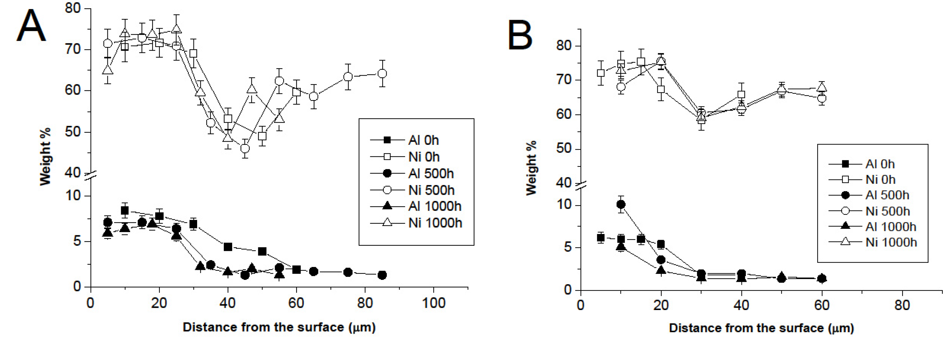
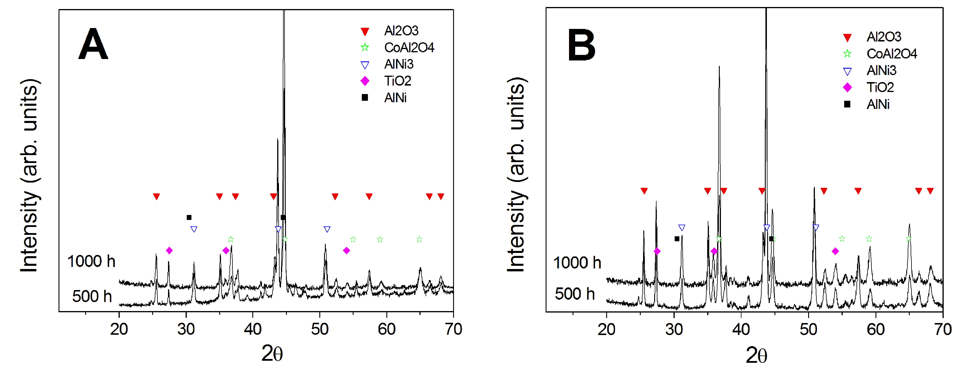
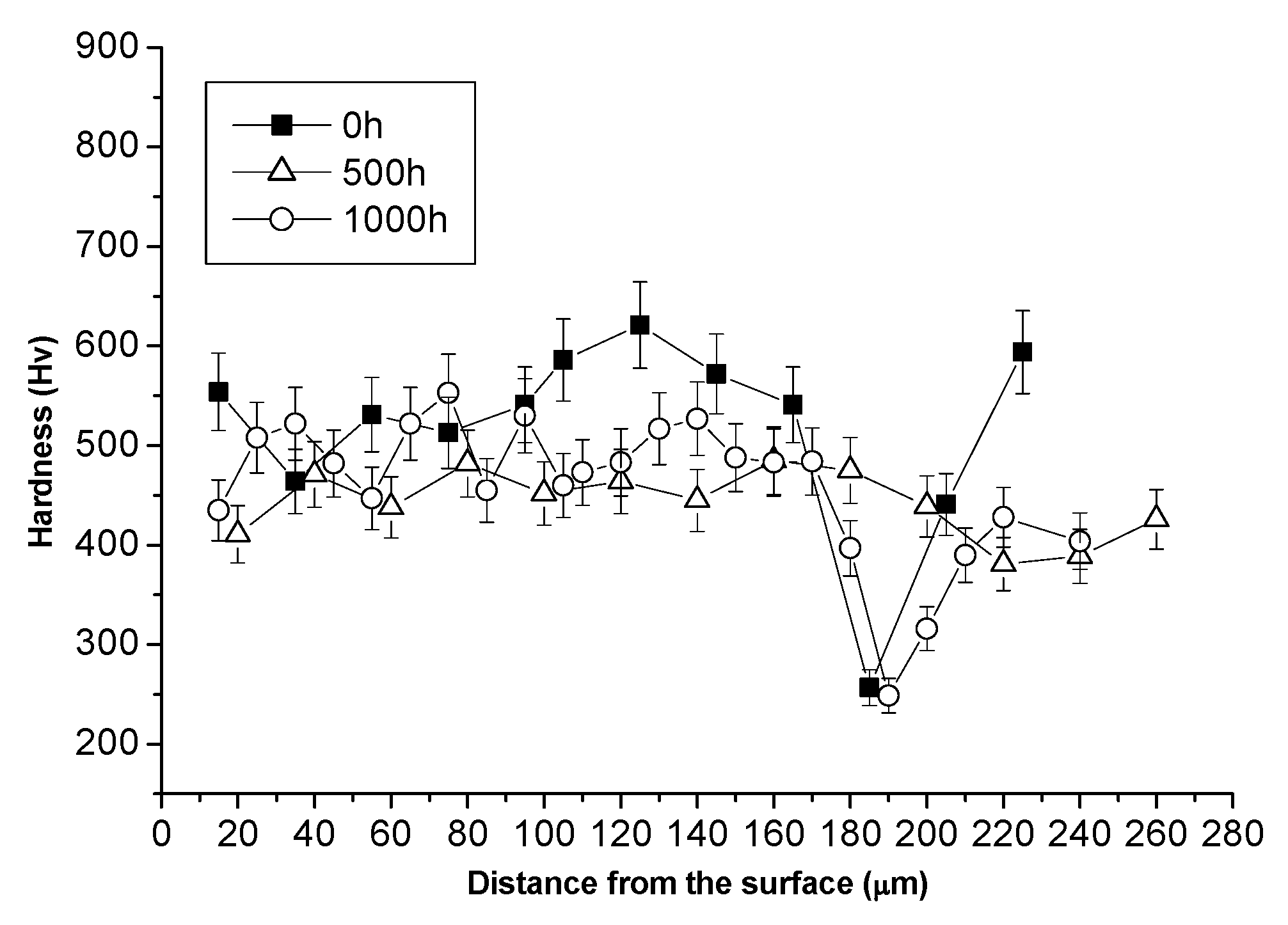
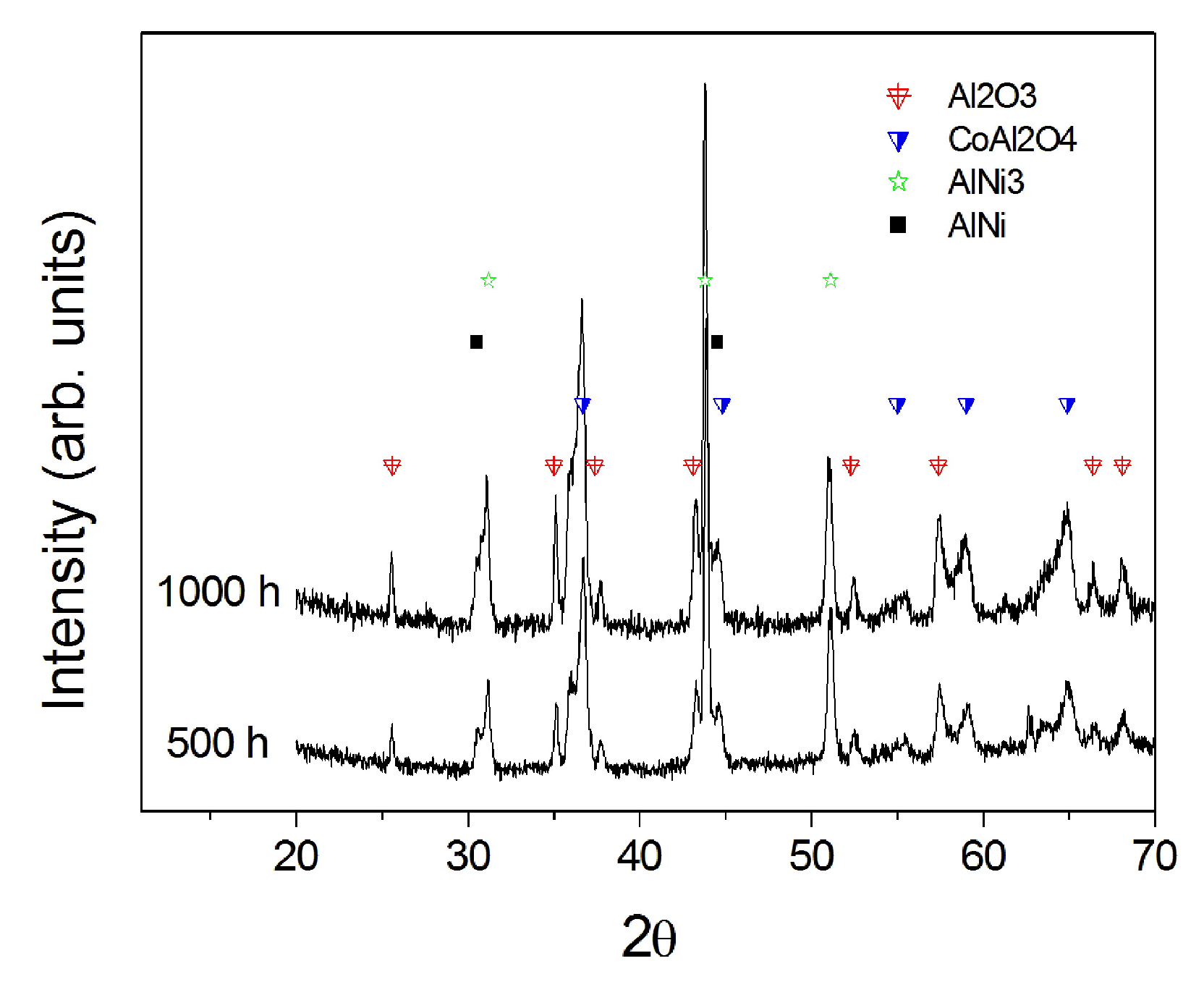
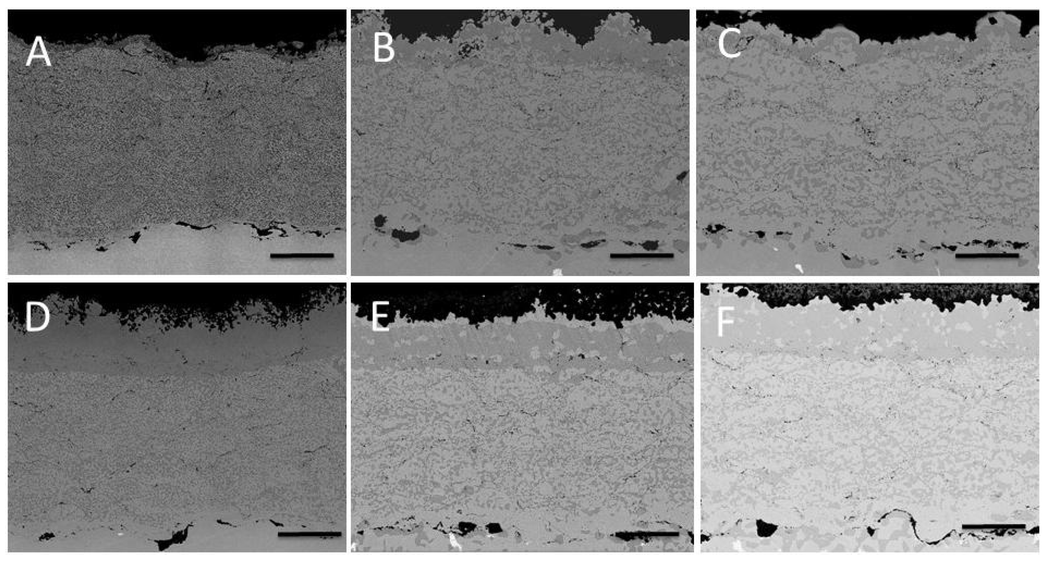
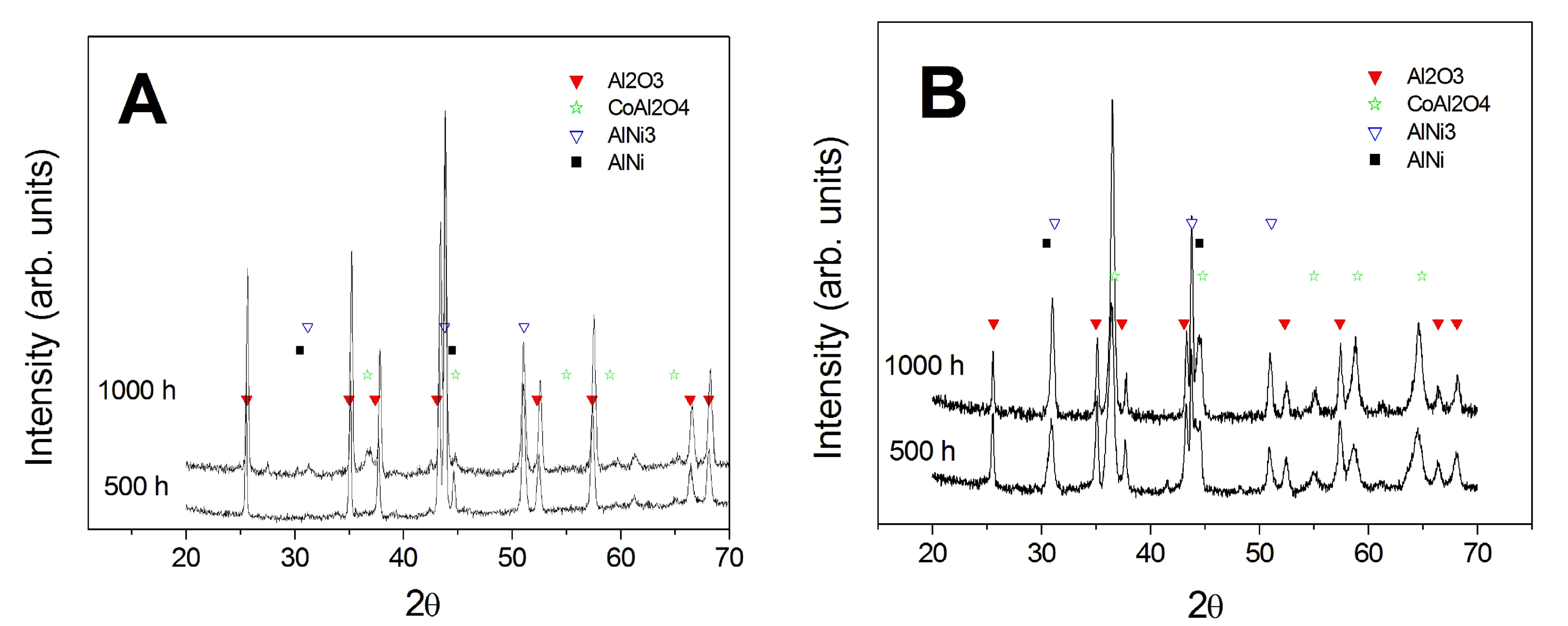
3.3. Comparison between Pack- and IL Over-Aluminizing

As a final evaluation, the results of isothermal tests for the two over-aluminizing processes (pack aluminizing and IL aluminizing) were compared.
Microstructural investigation of the cross sections (Figure 11) provides evidence of the different behavior and trends of the double-step coated and heat treated samples with respect to the standard aluminizing process over IN738 (see Section 3.1). In this case, no formation of carbides is detected and aluminum diffuses much deeper into the metallic coating with respect to the pack aluminizing.
These trends are also confirmed by the compositional profiles (Figure 12): Al in the IL over-aluminized CoNiCrAlY diffuses deeper than in the case of the pack aluminizing process increasing the β NiAl phase within a thicker CoNiCrAlY section. Figure 13 depicts the hardness variation across the coating of both the over-aluminized samples: little but detectable differences in the micro-hardness values indicate that it generally increases in the outermost portion of the coating due to the higher amount of Al diffused from the over-aluminized process. However, among the two over-aluminizing processes, the sample obtained via IL electrodeposition is characterized by larger hardness increase (from an average of 450 HV up to 700 HV in the more external portion of the coating, Figure 13B) due to the higher thickness of the over-aluminide coating itself with respect to the pack over-aluminide coatings.
XRD data (Figure 14) confirm the good resistance for both types of over-aluminized samples.

4. Conclusions

The results obtained in the present study can be summarized as follows:
  • Apparently, the two-step aluminizing process by Al-electrodeposition and consequent diffusion heat treatment (IL aluminizing) is not suitable for the direct application over IN738. Al inward diffusion seems to be inhibited by the possible formation of carbides or nitrides. These precipitates were observed after the diffusion post treatment, and they could result from the reaction of traces of ionic liquid entrapped in the growing Al layer with the base material. A further cleaning process could be attempted after the electroplating step in order to avoid the presence of IL residuals.
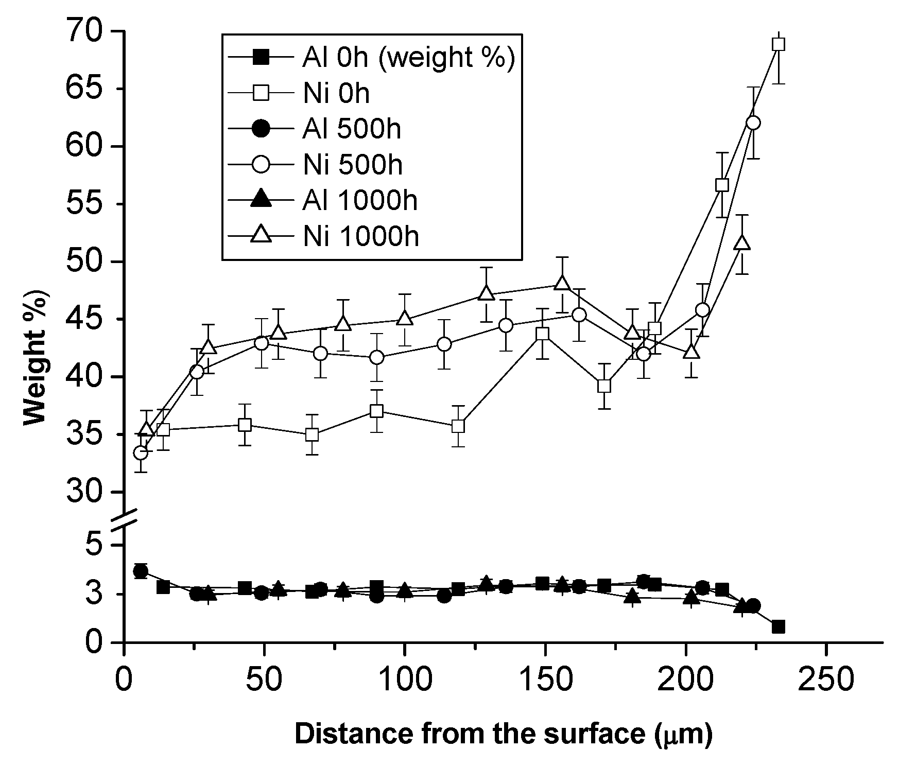
  • Over-aluminizing of CoNiCrAlY is beneficial in order to create a viable anti-corrosion coating. This is due to the high Ni interdiffusion from the base material to the coating. This behavior causes the transformation of the β NiAl into γ Ni3Al, which is less protective under oxidative and corrosive environment. For this reason, a further aluminizing step (over-aluminizing) is required for these types of metallic coatings in order to enhance the oxidation resistance at high temperatures.
  • Being virtually free of W, Ta, Ti, there is no formation of carbides in the CoNiCrAlY coat; therefore, IL over-aluminizing on CoNiCrAlY allows a better and deeper diffusion of the Al toward the coating with respect to the pack over-aluminizing process.
Overall, the IL aluminizing process results in being feasible and suitable as an over-aluminizing step onto CoNiCrAlY metallic coatings for high temperature oxidation protection but not for direct aluminizing of IN738.

Acknowledgments

The research leading to these results has received funding from the European Union Seventh Framework Programme (FP7/2007-2013) under Grant No. 608698. We wish to thank the IoLiTec Ionic Liquids Technologies GmbH (Heilbronn, Germany) for supplying the Ionic Liquid used in this study.

Author Contributions

Luca Tagliaferri and Stefano Caporali conceived and designed the experiments, analyzed the data, and wrote the paper; Stefano M. Martinuzzi realized the Al-electrodeposition from ionic liquid and Francesco Bozza via pack cementation. Enrico Berretti performed and analyzed the hardness profiles, and Andrea Giaccherini analyzed the XRD data. Martin Thoma and Ugo Bardi analyzed the data and contributed to the paper writing.

Conflicts of Interest

The authors declare no conflict of interest.

References

  1. Bozza, F.; Bolelli, G.; Giolli, C.; Giorgetti, A.; Lusvarghi, L.; Sassatelli, P.; Scrivani, A.; Candeli, A.; Thoma, M. Diffusion mechanisms and microstructure development in pack aluminizing of Ni-based alloys. Surf. Coat. Tech. 2014, 239, 147–159. [Google Scholar] [CrossRef]
  2. Xiang, Z.D.; Burnell-Gray, J.S.; Datta, P.K. Aluminide coating formation on nickel-base superalloys by pack cementation process. J. Mater. Sci. 2001, 36, 5673–5682. [Google Scholar] [CrossRef]
  3. Kim, D.; Sah, I.; Lee, H.J.; Hong, S.; Jang, C. Development of an aluminide coating layer on Alloy 617 by Al sputtering and inter-diffusion heat treatments. Surf. Coat. Technol. 2014, 244, 15–22. [Google Scholar] [CrossRef]
  4. Wang, Y.; Chen, W.; Wang, L. Micro-indentation and erosion properties of thermal sprayed NiAl intermetallic-based alloy coatings. Wear 2003, 254, 350–355. [Google Scholar] [CrossRef]
  5. Wang, Y.; Chen, W. Effect of ceria on the erosion resistance of HVOF thermal sprayed NiAl intermetallic coatings. J. Mater. Sci. Lett. 2003, 22, 845–851. [Google Scholar] [CrossRef]
  6. Deevi, S.C.; Sikka, V.K.; Liu, C.T. Processing, properties, and applications of nickel and iron aluminides. Prog. Mater. Sci. 1997, 42, 177–192. [Google Scholar] [CrossRef]
  7. Lih, W.; Chang, E.; Wu, B.C.; Chao, C.H. The effect of pack-aluminisation on the microstructure of MCrA1Y and the performance of thermal barrier coatings. Surf. Coat. Technol. 1992, 50, 277–288. [Google Scholar] [CrossRef]
  8. Chang, S.F.; Chao, C.H.; Wu, B.C.; Leu, R.Q.; Chang, E. Zirconia/pack-aluminized Co-29Cr-6AI-1Y thermal barrier coatings. J. Vac. Sci. Technol. A 1991, 9, 2099–2106. [Google Scholar] [CrossRef]
  9. Tong, L.; Dengzun, Y.; Chungen, Z. Low-temperature formation of aluminide coatings on Ni-base superalloys by pack cementation process. Chin. J. Aeronaut. 2010, 23, 381–385. [Google Scholar] [CrossRef]
  10. Svensson, H.; Angenete, J.; Stiller, K. Microstructure of oxide scales on aluminide diffusion coatings after short time oxidation at 1050 °C. Surf. Coat. Technol. 2004, 177–178, 152–157. [Google Scholar] [CrossRef]
  11. Fossati, A.; Ferdinando, M.; Lavacchi, A.; Scrivani, A.; Giolli, C.; Bardi, U. Improvement of the oxidation resistance of CoNiCrAlY bond coats sprayed by high velocity oxygen-fuel onto nickel superalloy substrate. Coatings 2011, 1, 3–16. [Google Scholar] [CrossRef]
  12. Choy, K.L. Chemical vapour deposition of coatings. Prog. Mater. Sci. 2003, 48, 57–170. [Google Scholar] [CrossRef]
  13. Thoma, M.; Scrivani, A.; Giolli, C.; Giorgetti, A. Aluminizing turbine parts—Processes and coatings. In Proceedings of the ASME Turbo Expo 2011, Vancouver, BC, Canada, 6–10 June 2011. [Google Scholar]
  14. Mishin, Y. Atomistic modeling of the γ and γ′-phases of the Ni–Al system. Acta Mater. 2004, 52, 1451–1467. [Google Scholar] [CrossRef]
  15. Wu, K.; Chang, Y.A.; Wang, Y. Simulating interdiffusion microstructures in Ni–Al–Cr diffusion couples: A phase field approach coupled with CALPHAD database. Scripta Mater. 2004, 50, 1145–1150. [Google Scholar] [CrossRef]
  16. Bardi, U.; Caporali, S.; Craig, M.; Lavacchi, A.; Nicholls, J. A Method for Making a Protective Coating on a Metal Substrate. European Patent No 2330233 A1, 1 December 2009. [Google Scholar]
  17. Abbott, A.P.; Harris, R.C.; Hsieh, Y.T.; Ryder, K.S.; Wen-Sun, I. Aluminium electrodeposition under ambient conditions. Phys. Chem. Chem. Phys. 2014, 16, 14675–14681. [Google Scholar] [CrossRef] [PubMed]
  18. Fang, Y.; Yoshii, K.; Jiang, X.; Sun, X.G.; Tsuda, T.; Mehio, N.; Dai, S. An AlCl3 based ionic liquid with a neutral substituted pyridine ligand for electrochemical deposition of aluminum. Electrochim. Acta 2015, 160, 82–88. [Google Scholar] [CrossRef]
  19. Wang, Q.; Chen, B.; Zhang, Q.; Lu, X.; Zhang, S. Aluminium deposition from lewis acidic 1-butyl-3-methylimidazolium chloroaluminate ionic liquid ([Bmim]Cl/AlCl3) modified with methyl nicotinate. ChemElectroChem 2015, 2, 1794–1798. [Google Scholar] [CrossRef]
  20. Wang, Q.; Zhang, Q.; Chen, B.; Lu, X.; Zhang, S. Electrodeposition of bright Al coatings from 1-butyl-3-methylimidazolium chloroaluminate ionic liquids with specific additives. J. Electrochem. Soc. 2015, 162, D320–D324. [Google Scholar] [CrossRef]
  21. Zheng, Y.; Zhang, S.; Lu, X.; Wang, Q.; Zuo, Y.; Liu, L. Low-temperature electrodeposition of aluminium from lewis acidic 1-allyl-3-methylimidazolium chloroaluminate ionic liquids. Chin. J. Chem. Eng. 2012, 20, 130–139. [Google Scholar] [CrossRef]
  22. Berretti, E.; Giaccherini, A.; Martinuzzi, S.M.; Innocenti, M.; Schubert, T.J.S.; Stiemke, F.M.; Caporali, S. Aluminium Electrodeposition from Ionic Liquid: Effect of Deposition Temperature and Sonication. Materials 2016, 9, 719. [Google Scholar] [CrossRef]
  23. Project Scail-Up. Scaling-Up of the Aluminium Plating Process from Ionic Liquid. Available online: http://scailup.eu (accessed on 25 February 2017).
  24. Caporali, S.; Martinuzzi, S.M.; von Czarnecki, P.; Schubert, T.J.S.; Bardi, U. Effects of metal ions on the aluminum electrodeposition from ionic liquids. J. Mater. Eng. Perform. 2017, 26, 685–691. [Google Scholar] [CrossRef]
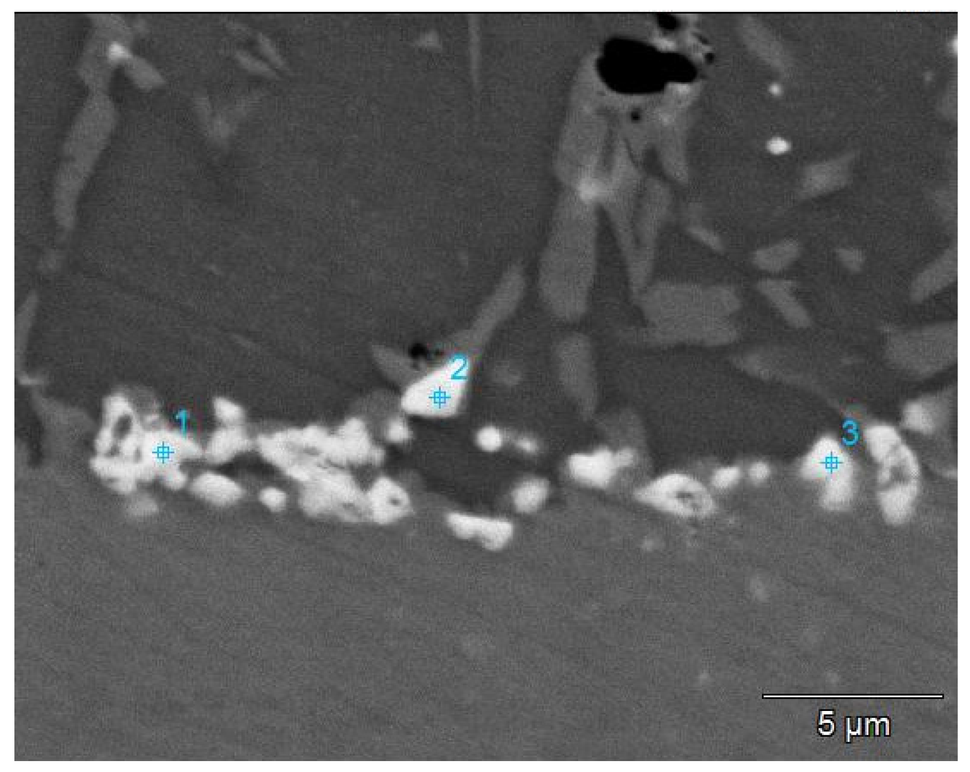
Figure 1. SEM images (SE signal) of the aluminum coating on bare IN738 (A) and CoNiCrAlY coated IN738 (B) before the heat treatment. In both cases, a pure Al layer about 20 μm thick is detectable on the top of the sample.
Coatings 07 00083 g001
Figure 2. SEM images (BSE signal) of the aluminized IN738 as function of the isothermal test duration (A,D = 0 h; B,E = 500 h; C,F = 1000 h) for IN738 + pack aluminizing + heat treatment (AC) and IN738 + IL Aluminizing + heat treatment (DF). Scale bar 25 μm.
Coatings 07 00083 g002
Figure 3. SEM image (BSE signal) of the interphase between IL aluminide coating and IN738 substrate. Numbers indicate the spots on which EDS analysis was performed. Scale bar 25 μm.
Coatings 07 00083 g003
Figure 4. Compositional profiles of Al (full symbols) and Ni (empty symbols) for the cross sections depicted in Figure 1 as determined by EDS measurement. (A) and (B) panels depict data for IN738 + pack aluminizing + heat treatment and IN738 + IL aluminizing + heat treatment, respectively.
Coatings 07 00083 g004
Figure 5. Hardness profile measurement for IN738 + Pack aluminizing + Post treatment (A) and IN738 + IL aluminizing + post treatment (B), respectively, at 0, 500 and 1000 h of isothermal test (1000 °C).
Coatings 07 00083 g005
Figure 6. Surface XRD pattern of IN738 + Pack aluminizing + Post treatment (A) and IN738 + IL aluminizing + post treatment (B), respectively, after 500 and 1000 h of isothermal test (1000 °C).
Coatings 07 00083 g006
Figure 7. SEM micrographs for the HVOF sprayed CoNiCrAlY + heat treatment at 0 h (A), 500 h (B) and 1000 h (C) of isothermal test. Scale bar 50 μm.
Coatings 07 00083 g007
Figure 8. Ni and Al concentration profile for HVOF sprayed CoNiCrAlY on IN738 at 0, 500 and 1000 h of isothermal test.
Coatings 07 00083 g008
Figure 9. Micro-hardness profiles of HVOF sprayed CoNiCrAlY on IN738 + heat treatment at 0, 500 and 1000 h of isothermal test.
Coatings 07 00083 g009
Figure 10. XRD analysis performed on HVOF sprayed CoNiCrAlY on IN738 + heat treatment at 500 and 1000 h of isothermal test.
Coatings 07 00083 g010
Figure 11. SEM images (BSE signal) of the over-aluminized IN738 + CoNiCrAlY as function of the isothermal test duration (A,D = 0 h; B,E = 500 h; C,F = 1000 h) for IN738 + CoNiCrAlY + pack aluminizing + heat treatment (AC) and IN738 + CoNiCrAlY + IL Aluminizing + heat treatment (DF). Scale bar 50 μm.
Coatings 07 00083 g011
Figure 12. Compositional profiles of Al (full symbols) and Ni (empty symbols) for the cross sections depicted in Figure 10 as determined by EDS measurement. (A) and (B) panels depict data for IN738 + CoNiCrAlY + IL aluminizing + heat treatment and IN738 CoNiCrAlY + Pack aluminizing + heat treatment, respectively.
Coatings 07 00083 g012
Figure 13. Hardness profile measurement for IN738 + CoNiCrAlY + Pack aluminizing + Post treatment (A) and IN738 + CoNiCrAlY + IL aluminizing + post treatment (B), respectively, at 0, 500 and 1000 h of isothermal test (1000 °C).
Coatings 07 00083 g013
Figure 14. Surface XRD pattern of IN738 + CoNiCrAlY + Pack aluminizing + Post treatment (A) and IN738 + CoNiCrAlY + IL aluminizing + post treatment (B), respectively, after 500 and 1000 h of isothermal test (1000 °C).
Coatings 07 00083 g014
Table 1. EDS spot analysis over the points depicted in Figure 2.
ElementPoint 1Point 2Point 3
Al0.20.40.3
Ti3.71.715.5
Cr50.445.93.3
Co2.13.82.5
Ni13.225.320.7
Mo12.09.3
W18.413.6
Nb4.7
Ta53.0

