
Plastic Deformation Induced by Nanoindentation Test Applied on ZrN/Si3N4 Multilayer Coatings

1
School of Electromechanical Engineering, Guangdong University of Technology, Guangzhou 510006, China
2
College of Chemistry and Chemical Engineering, Xiamen University, Xiamen 361005, China
*
Authors to whom correspondence should be addressed.
Coatings 2018, 8(1), 11; https://doi.org/10.3390/coatings8010011
Submission received: 20 November 2017
/
Revised: 22 December 2017
/
Accepted: 25 December 2017
/
Published: 27 December 2017
(This article belongs to the Special Issue Hybrid Surface Coatings & Process (Selected Papers from HyMaP 2017))
Abstract
:ZrN/Si3N4 multilayer coating that alternates with either nanocrystalline ZrN or amorphous Si3N4 interlayers was fabricated by reactively magnetron sputtering in an Ar-N2 mixture atmosphere. The thicknesses of the nanocrystalline ZrN and the amorphous Si3N4 interlayers are ~12.5 and 2.5 nm, respectively. The ZrN/Si3N4 coating exhibits a promoted hardness of 28.6 ± 1.2 GPa when compared to the binary ZrN. Microstructure evolution just underneath the nanoindentation impression of the ZrN/Si3N4 multilayer coating has been investigated. The result indicates that both ZrN nanograin rotations and plastic flow of the Si3N4 interlayers contribute to the permanent deformation of the multilayer coating induced by the nanoindentation. In addition, the introduction of the a-Si3N4 interlayers hinders both the initiation and propagation of microcracks when the multilayer coating was applied to the scratch test. The propagation deflection of the microcracks was observed attributed to the heterogenous interface, which produces the hardness promotion of the multilayer coating eventually.
1. Introduction
Nanocrystalline materials with average grain sizes vary in the range of 1–100 nm show great promise for applications in engineering, owing to their high strength yet toughness when compared to the bulk materials [1,2,3]. Investigations into materials with ultrahigh hardness or strength produce require of the search for effective obstacles to dislocation movements or motions. Generally, it is well known that grain boundaries (GBs) preferentially suppress the dislocation movements or motions [4,5]. The dislocation movements or motions become the primary attributions for the occurrence of plastic deformation in crystalline alloys. However, absorption of the dislocations preferentially occurs at the GBs. Thus, the nanocrystalline materials often suffer a limited ductility. Reports on the nanocrystalline materials have revealed that a fine-grained material contains fewer dislocations [6,7]. In particular, the transition from a dislocation to a GBs-based deformation mechanism occurs as the average crystalline sizes of the materials decrease to tens of nanometers [8,9]. Therefore, the GB-based mechanisms, such as grain sliding and rotations, have been accounted for the permanent deformation occurred in the nanocrystalline alloys [10,11].
Transition metal nitride coatings have been deposited on cutting tools to improve their lifetime and working efficiency over the past decades [12,13,14,15]. The fabrication and characterization of nanocrystallized yet multilayered nitride coatings have attracted many attentions due to their excellent performance [16,17,18], such as high hardness, strong toughness, etc. These multilayered structures consist of repeating interlayers of two different materials with nanometer-scale thicknesses. The bilayer period in multilayer coatings is defined as the sum thickness of two neighbouring interlayers, which shows significant impact on coating performance (hardness, toughness, adhension strength, wear resistance, etc.) [19,20]. To date, plenty of reported works on multilayer coatings focused on the nitride-based materials of great interest as superhard coatings and wear-resistance applications [21,22]. Nevertheless, both deformation behavior and mechanism behind the structure evolution of the deformed zone of the nitride hard coatings are still less dealt with. Wieciński et al. [23] have observed occurrence of radial cracks underneath the indentation of Cr/CrN multilayer coating. However, the thicknesses of the Cr and the CrN layers in this coating varied in the ranges of 0.09–0.26 and 0.32–0.56 μm, respectively. Columnar grains could be observed in a Cr or CrN interlayers with large thickness. Jamison et al. [24] investigated the deformation behavior of aluminum/silicon carbide multilayered thin films during the nanoindentation test using the finite element method. Plastic strain development is amplified along the Al-substrate interface, and the tensile axial stress is broken into bands that correspond to various features in the waveforms [24]. Based on these above investigations, the plastic deformation behaviors of the nitride/nitride type-multilayer coatings are relatively unclear. The effect of introducing the heterogenous interface on the cracking behaviors of the multilayer coatings is still unknown as well. Therefore, this work investigated the microstructure evolution just underneath the nanoindentation impression of the ZrN/Si3N4 multilayer coating. This aims to make a better understanding of the plastic deformation behaviors of the multilayer coating.
2. Materials and Methods
The ZrN/Si3N4 multilayer coating was deposited on WC-6Co (6 wt % Co) substrates using magnetron sputtering in N2-Ar mixture atmosphere (99.999% purity for each gas). Both zirconium (Ø 76 mm, purity 99.9%) and Si3N4 targets (Ø 76 mm, purity 99.9%) were used during the sputtering. The targets were pre-sputtered for 10 min to remove the surface oxides and contaminants after the deposition chamber reaches a base pressure of 6.0 × 10⁻⁴ Pa. During coating deposition, the working pressure was set at 0.30 Pa, and the total gas (Ar and N2) flow rate was maintained at 60 sccm. The ratio of the N2 flow rate over the total flow rate was fixed at 20%. The Zr target DC power (Advanced Energy, Fort Collins, CO, USA) and the Si3N4 target RF power (Advanced Energy, Fort Collins, CO, USA) were fixed at 250 and 150 W, respectively. No bias was applied to the substrate (0 V, grounded) and the deposition temperature was 300 °C. The thicknesses of the ZrN and the Si3N4 interlayers were controlled by controlling the opening times of the baffles.
The phase composition of the ZrN/Si3N4 multilayer coatings was confirmed by Panalytical X’pert PRO X-ray diffraction (XRD, Philips, Amsterdam, The Netherlands), using Cu Kα radiation (0.154 nm wavelength) as the X-ray source. X-ray photoelectron spectroscope (XPS, PHI-Quantum 2000, Physical Electronics, Inc., Chanhassen, MN, USA) was employed to investigate the chemical bonding states of the ZrN/Si3N4 multilayer coatings. The revetest scratch tests with a Rockwell C diamond tip (Ø 100 μm) have been conducted on both the ZrN monolayer and the ZrN/Si3N4 multilayer coatings. A linearly increasing load from 0.9 to 50 N was applied. The loading rate was 98.2 N/min and the scratch distance was 3 mm. Both fabrication of the deformation zone and measurement of the coating hardness were conducted using the nanoindentation test (CSM Instrument SA, Peseux, Switzerland), with a diamond Berkovich indenter. The penetration depth of the indenter was maintained at ~1/10 of the coating thickness, in order to minimize the influence of the substrate deformation to the coating. During the nanoindentation test, both loading and unloading times of the indenter were set as 30 s. In addition, a 10 s holding time was applied to release the material creep. Subsequently, the focused ion beam system (FIB, Quanta 3D 200i, Thermo Fisher Scientific, Waltham, MA, USA) was used to cut the nanoindentation impression to fabricate a cross-sectional TEM (transmission electron microscopy) sample. A detailed description of the preparation processes of the sample can be found elsewhere [25,26]. The evolution behind the microstructure of the nano-indented zone was observed using TEM (Tecnai G2 F20, Thermo Fisher Scientific, Waltham, MA, USA).
3. Results and Discussions
Figure 1a exhibits the normal XRD pattern of the ZrN/Si3N4 multilayer coating. In addition to the WC substrate, the pattern reveals the formation of the FCC crystallized ZrN (JCPDS No. 35-0753). In Figure 1b, Zr 3d spectrum show fitted peaks at 179.1 and 181.5 eV, which correspond to Zr 3d5/2 and Zr 3d3/2 components of the ZrN [27], respectively. Additionally, two peaks located at 182.2 and 184.6 eV, which belong to ZrO2, can be noticed as well. This demonstrates that a minor trace of the ZrN oxidation occurred on the surface of the coating. In Figure 1c, Si 2p peak reveals a binding energy of 101.8 eV, which belongs to the Si 2p component of the Si3N4 [28]. The result indicates that the interface phase is the stoichiometric Si3N4, which is similar to the reported Zr–Si–N nanocomposite coatings [26]. Moreover, since no diffraction signals corresponding to crystalline Si3N4 were found in the XRD pattern (Figure 1a), the Si3N4 interlayers were confirmed to be amorphous state (further revealed by HRTEM investigation below).
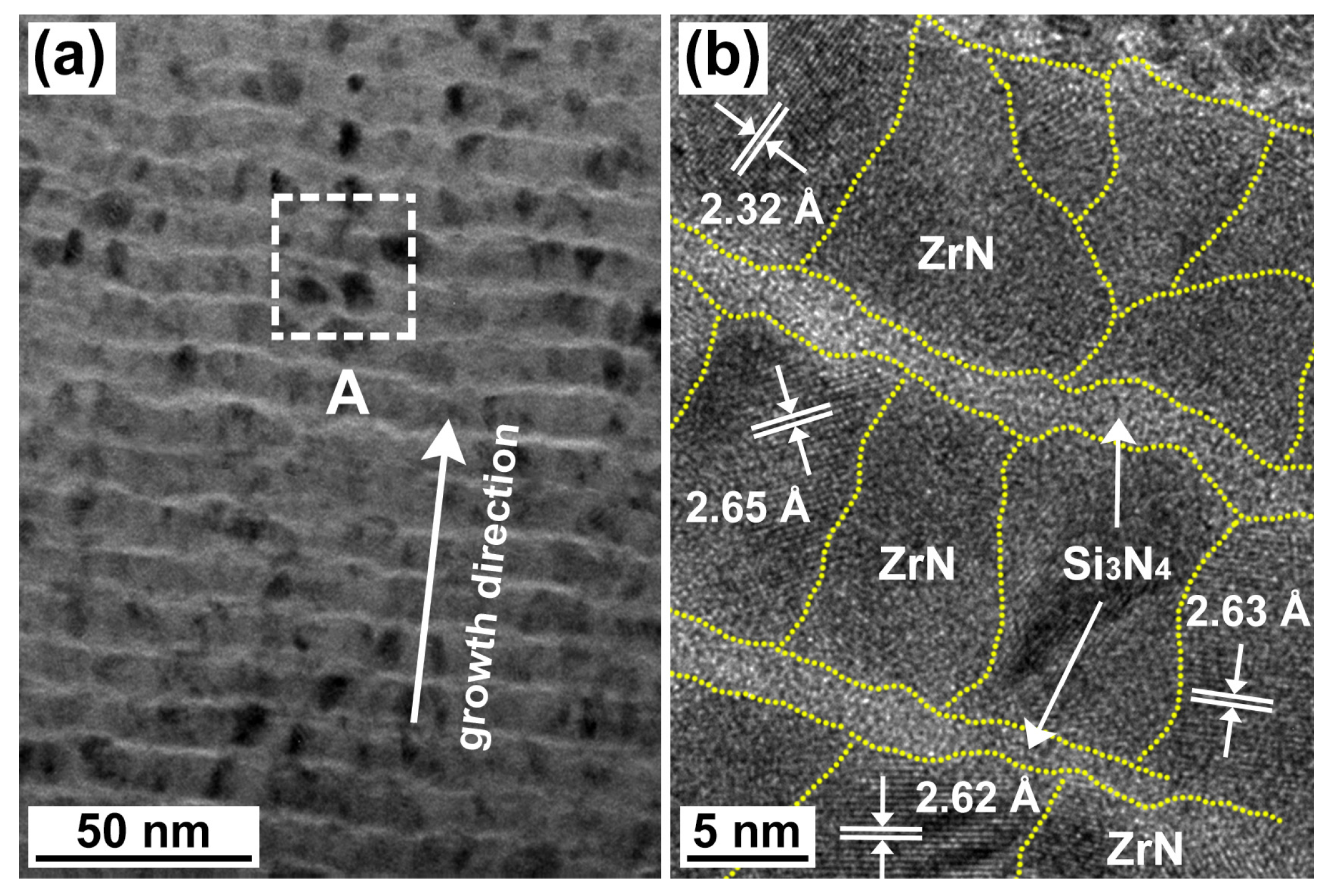
Figure 2 shows the cross-sectional TEM images of the ZrN/Si3N4 multilayer coating. In Figure 2a, the overall morphology of the ZrN/Si3N4 multilayer coating illustrates a uniform multilayer microstructure. An analytical HRTEM investigation was carried out to obtain a structural insight into both the ZrN and the Si3N4 interlayers. The result was exhibited in Figure 2b. The HRTEM image indicates that the ZrN interlayer reveals the equiaxial grains with the average crystalline sizes of 5–10 nm, whereas the Si3N4 interlayer exhibits an amorphous microstructure. In addition, the thicknesses of the ZrN and the Si3N4 interlayers exhibited in Figure 2b are ~12.5 and 2.5 nm, respectively. The reason for the coating deposition with such interlayer thicknesses was that the multilayer coating exhibits a promoted hardness when compared to the binary ZrN.
Figure 3 exhibits loading vs. penetration depth curves of the nanoindentation tests that were applied on the ZrN monolayer and the ZrN/Si3N4 multilayer coatings. In addition to the ZrN/Si3N4 multilayer coating, the ZrN monolayer coating with a thickness of 2.2 μm has been deposited by reactive magnetron sputtering from the cylindrical Zr target as well [25]. The ZrN monolayer coating illustrates a dense yet columnar microstructure. The columnar ZrN grains exhibit an average width of ~70 nm. The details of the hardness measurement of the ZrN monolayer coating are similar to the ZrN/Si3N4 multilayer coating. The hardness of the ZrN/Si3N4 was measured to be 28.6 ± 1.2 GPa, which is larger than that of the ZrN monolayer coating, i.e., 22.3 ± 0.6 GPa [25]. The maximum penetrated and residual depths of the nanoindentation on the ZrN/Si3N4 multilayer coating are ~230 and 118 nm, respectively. Thus, the elastic recovery of the ZrN/Si3N4 multilayer coating was calculated to be ~0.49, which is also higher than that of the ZrN monolayer coating as well, i.e., ~0.37 [25].
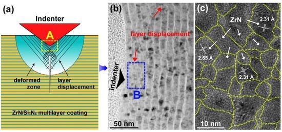
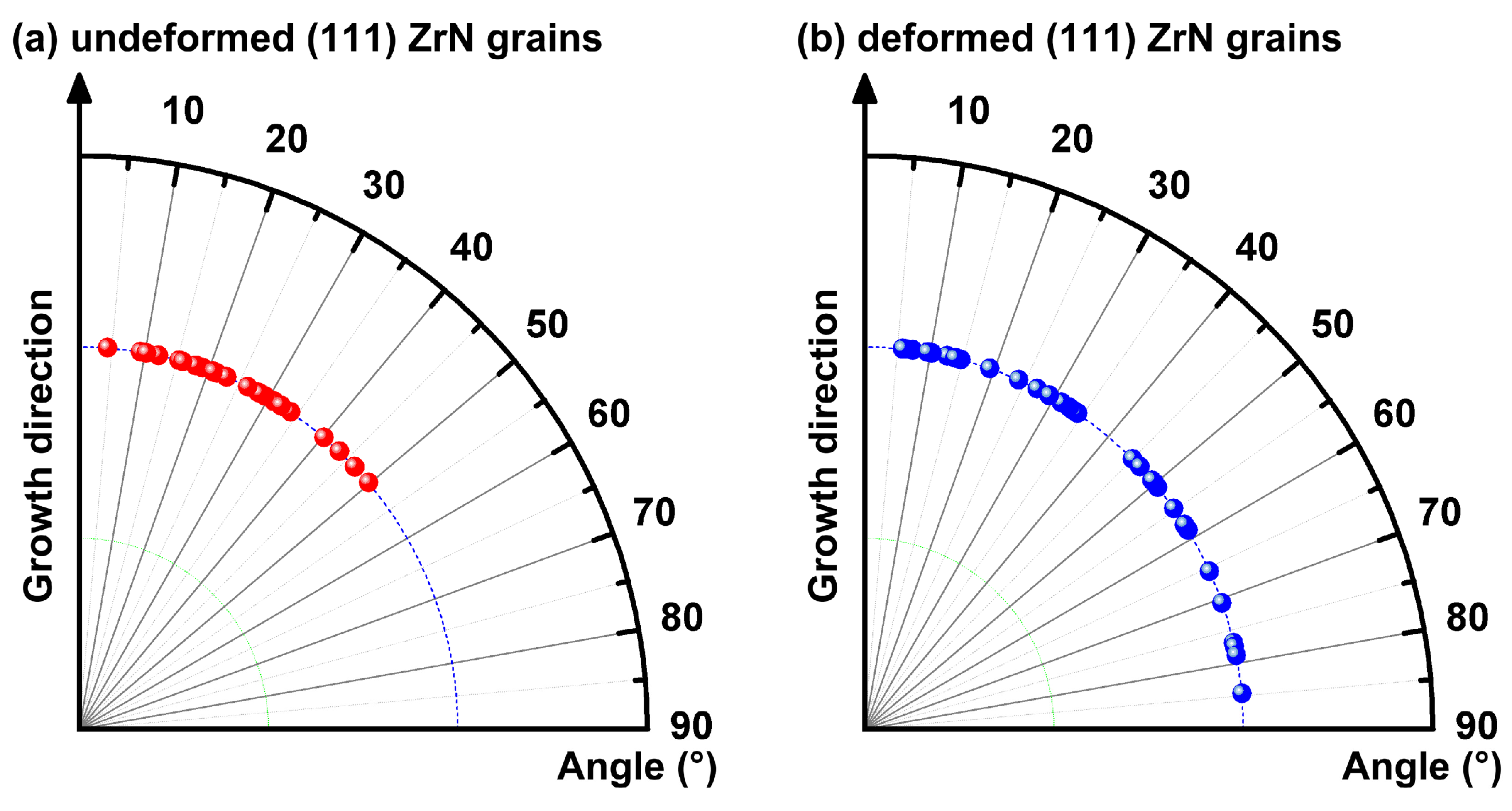
Figure 4 shows cross-sectional TEM micrographs of the nanoindentation test produced deformation zone in the ZrN/Si3N4 multilayer coating. In Figure 4a, a dense yet multilayer microstructure can be observed in the multilayer coating. The nanoindentation impression illustrates a residual depth of 115–120 nm, showing agreement with the result of the recorded loading–penetration depth curves (Figure 3). In Figure 4b, the SAED (selected area electron diffraction) pattern further confirms the FCC crystallization of the ZrN interlayers. In Figure 4c, displacement (marked by solid arrows) of the ZrN interlayers can be found. This shows significant difference when compared to the nano-indented zone of the ZrN monolayer coating, which consists of dislocation gliding, microcrack initiation and propagation [25]. Figure 5 shows the magnified TEM images of the deformation zone just underneath the indentation impression of the ZrN/Si3N4 multilayer coating. In Figure 5b, both the ZrN and the Si3N4 interlayers just underneath the contact surface are not perfectly straight and exhibit an undulation. For the amorphous Si3N4 interlayers, the plastic flow of the Si3N4 was expected to occur (marked by dashed arrows). This produces the permanent deformation of the Si3N4 interlayers [29,30]. For the deformed ZrN interlayers (marked by solid arrows), the angular deviations in growth directions between the (111) ZrN nanograins and the multilayer coating were estimated using the HRTEM images. The HRTEM images (Figure 2b and Figure 5b) that were acquired just underneath the contact surface between the indenter and the multilayer coating were used. The estimated results are illustrated in Figure 6. In Figure 6a, the angular deviation in growth directions between the undeformed (111) ZrN nanograins and the multilayer coating (estimated form Figure 2b) varies in a range of 9.3°–49.8°. However, for the nano-indented zone of the ZrN/Si3N4 multilayer coating, the direction of the deformed (111) ZrN nanograins and the initial growth direction of the coating differs in a range of 5.8°–84.6°, as shown in Figure 6b. These above results indicate that the ZrN nanograin rotation or sliding occured during the penetration of the indenter, resulting in the ZrN interlayer displacement [24]. Therefore, it was concluded that the ZrN nanograin rotation or sliding together with the plastic flow of the Si3N4 interlayers contribute to the permanent deformation of the ZrN/Si3N4 multilayer coating.
Interestingly, for the binary ZrN monolayer coating (thickness 2.2 μm), plenty of microcracks preferentially initiate just underneath the indenter tip and then propagate along the columnar GBs [25,26]. The microcrack propagation along the columnar GBs is found to be the primary factor that deteriorates both hardness and strength of the ZrN monolayer coating. However, it was noticed that no microcracks could be found both in the crystalline ZrN and the amorphous Si3N4 interlayers. This suggests that introducing the amorphous Si3N4 interlayers suppresses both the formation and propagation of the microcracks when the ZrN/Si3N4 multilayer coating was exposed to the nanoindenter. Scanning electron microscope (SEM) was employed to observe the scratch tracks of the coatings. As shown in Figure 7, the fracture faces (marked by arrows) of the ZrN coating is perpendicular to the Si substrate. However, for the ZrN/Si3N4 multilayer coating, oblique fracture faces (marked by arrows) can be observed. When a heavy loading such as the revetest scratch test was applied on the ZrN monolayer coating surface, the microcrack propagation along the columnar GBs preferentially occurs, resulting in the formation of the smooth fracture faces. Since no columnar grain boundaries formed in the ZrN/Si3N4 multilayer coating, the microcrack propagation no longer exhibits the priority in the direction that is perpendicular to the substrate. Therefore, the deflection of the microcrack propagation produces the oblique fracture faces. Figure 7c,d show higher magnification images of the microcrack tip on the ZrN and the ZrN/Si3N4 coatings. In Figure 7c, the microcrack propagation along the columnar GBs of the ZrN monolayer coating preferentially occurs. In Figure 7d, since the outside interlayer of the ZrN/Si3N4 coating is the ZrN interlayer (see Figure 4 and Figure 5). Thus, the microcrack propagation along the GBs of the granular ZrN nanograins can be observed. These above results further confirm that introducing the amorphous Si3N4 interlayer suppresses both the formation and the propagation of the microcracks as the ZrN/Si3N4 multilayer coating exposed to the heavy loads. This becomes the primary factor accounting for the promotions of the hardness and the toughness of the ZrN/Si3N4 multilayer coating when compared to the binary ZrN monolayer coating.
4. Conclusions
In summary, the ZrN/Si3N4 multilayer coating has been deposited by reactively co-sputtering. Evolution behind the microstructure of the nano-indented region of the ZrN/Si3N4 was investigated. The plastic deformation of the ZrN/Si3N4 multilayer coating probably occurs by the ZrN nanograin rotations and the plastic flow of the Si3N4 interlayers. Introducing the Si3N4 interlayers suppresses both the formation and propagation of the microcracks as the ZrN/Si3N4 multilayer coating exposed to a heavy load. During the cracking of the ZrN/Si3N4 coating, the propagation deflection of the microcracks has been achieved. Consequently, the ZrN/Si3N4 multilayer coating illustrates a promoted hardness yet toughness as compared to the ZrN monolayer coating.
Acknowledgments
The authors thank the National Natural Science Foundation of China (Grant No.: 51522502, 51372212), China Postdoctoral Science Foundation (2016M600641) and Guangdong Natural Science Funds (2016A050502056) for financial supports.
Author Contributions
Zhengtao Wu and Zhoucheng Wang conceived and designed the experiments; Xing Zhong performed the experiments; Cihai Liu and Wei Dai analyzed the data; Qimin Wang contributed reagents/materials/analysis tools; Zhengtao Wu wrote the paper.
Conflicts of Interest
The authors declare no conflict of interest.
References
- Gleiter, H. Nanostructured materials: Basic concepts and microstructure. Acta Mater. 2000, 48, 1–29. [Google Scholar] [CrossRef]
- Bringa, E.M.; Caro, A.; Wang, Y.; Victoria, M.; McNaney, J.M.; Remington, B.A.; Smith, R.F.; Torralva, B.R.; van Swygenhoven, H. Ultrahigh strength in nanocrystalline materials under shock loading. Science 2005, 309, 1838–1841. [Google Scholar] [CrossRef] [PubMed]
- Meyers, M.A.; Mishra, A.; Benson, D.J. Mechanical properties of nanocrystalline materials. Prog. Mater. Sci. 2006, 51, 427–556. [Google Scholar] [CrossRef]
- Gutkin, M.Y.; Ovid’ko, I.; Skiba, N. Crossover from grain boundary sliding to rotational deformation in nanocrystalline materials. Acta Mater. 2003, 51, 4059–4071. [Google Scholar] [CrossRef]
- Lu, L.; Shen, Y.; Chen, X.; Qian, L.; Lu, K. Ultrahigh strength and high electrical conductivity in copper. Science 2004, 304, 422–426. [Google Scholar] [CrossRef] [PubMed]
- Yamakov, V.; Wolf, D.; Phillpot, S.R.; Mukherjee, A.K.; Gleiter, H. Dislocation processes in the deformation of nanocrystalline aluminium by molecular-dynamics simulation. Nat. Mater. 2002, 1, 45–48. [Google Scholar] [CrossRef] [PubMed]
- Carlton, C.; Ferreira, P. What is behind the inverse Hall–Petch effect in nanocrystalline materials? Acta Mater. 2007, 55, 3749–3756. [Google Scholar] [CrossRef]
- Li, H.; Choo, H.; Ren, Y.; Saleh, T.A.; Lienert, U.; Liaw, P.K.; Ebrahimi, F. Strain-dependent deformation behavior in nanocrystalline metals. Phys. Rev. Lett. 2008, 101, 015502. [Google Scholar] [CrossRef] [PubMed]
- Mughrabi, H.; Höppel, H.W. Cyclic deformation and fatigue properties of very fine-grained metals and alloys. Int. J. Fatigue 2010, 32, 1413–1427. [Google Scholar] [CrossRef]
- Wu, X.; Zhu, Y. Partial-dislocation-mediated processes in nanocrystalline Ni with nonequilibrium grain boundaries. Appl. Phys. Lett. 2006, 89, 031922. [Google Scholar] [CrossRef]
- El-Awady, J.A. Unravelling the physics of size-dependent dislocation-mediated plasticity. Nat. Commun. 2015, 6, 5926. [Google Scholar] [CrossRef] [PubMed]
- Sproul, W.D. Physical vapor deposition tool coatings. Surf. Coat. Technol. 1996, 81, 1–7. [Google Scholar] [CrossRef]
- Mitterer, C.; Holler, F.; Reitberger, D.; Badisch, E.; Stoiber, M.; Lugmair, C.; Nöbauer, R.; Müller, T.; Kullmer, R. Industrial applications of PACVD hard coatings. Surf. Coat. Technol. 2003, 163, 716–722. [Google Scholar] [CrossRef]
- Veprek, S.; Veprek-Heijman, M.J. Industrial applications of superhard nanocomposite coatings. Surf. Coat. Technol. 2008, 202, 5063–5073. [Google Scholar] [CrossRef]
- Zhang, S.; Zhang, X. Toughness evaluation of hard coatings and thin films. Thin Solid Films 2012, 520, 2375–2389. [Google Scholar] [CrossRef]
- Hovsepian, P.E.; Lewis, D.; Münz, W.D. Recent progress in large scale manufacturing of multilayer/superlattice hard coatings. Surf. Coat. Technol. 2000, 133, 166–175. [Google Scholar] [CrossRef]
- Musil, J. Hard and superhard nanocomposite coatings. Surf. Coat. Technol. 2000, 125, 322–330. [Google Scholar] [CrossRef]
- Mayrhofer, P.H.; Mitterer, C.; Hultman, L.; Clemens, H. Microstructural design of hard coatings. Prog. Mater. Sci. 2006, 51, 1032–1114. [Google Scholar] [CrossRef]
- Ducros, C.; Benevent, V.; Sanchette, F. Deposition, characterization and machining performance of multilayer PVD coatings on cemented carbide cutting tools. Surf. Coat. Technol. 2003, 163, 681–688. [Google Scholar] [CrossRef]
- PalDey, S.; Deevi, S.C. Single layer and multilayer wear resistant coatings of (Ti,Al)N: A review. Mater. Sci. Eng. A 2003, 342, 58–79. [Google Scholar] [CrossRef]
- Jehn, H.A. Multicomponent and multiphase hard coatings for tribological applications. Surf. Coat. Technol. 2000, 131, 433–440. [Google Scholar] [CrossRef]
- Çalışkan, H.; Kurbanoğlu, C.; Panjan, P.; Čekada, M.; Kramar, D. Wear behavior and cutting performance of nanostructured hard coatings on cemented carbide cutting tools in hard milling. Tribol. Int. 2013, 62, 215–222. [Google Scholar] [CrossRef]
- Wiecinski, P.; Smolik, J.; Garbacz, H.; Kurzydlowski, K.J. Failure and deformation mechanisms during indentation in nanostructured Cr/CrN multilayer coatings. Surf. Coat. Technol. 2014, 240, 23–31. [Google Scholar] [CrossRef]
- Jamison, R.D.; Shen, Y.L. Indentation behavior of multilayered thin films: Effects of layer undulation. Thin Solid Films 2014, 570, 235–242. [Google Scholar] [CrossRef]
- Wu, Z.; Qi, Z.; Zhang, D.; Wang, Z. Nanoindentation induced plastic deformation in nanocrystalline ZrN coating. Mater. Lett. 2016, 164, 120–123. [Google Scholar] [CrossRef]
- Wu, Z.; Qi, Z.; Wei, B.; Zhang, D.; Wang, Z. Understanding hardness evolution of Zr–Si–N nanocomposite coatings via investigating their deformation behaviors. J. Eur. Ceram. Soc. 2016, 36, 3329–3339. [Google Scholar] [CrossRef]
- Matsuoka, M.; Isotani, S.; Sucasaire, W.; Kuratani, N.; Ogata, K. X-ray photoelectron spectroscopy analysis of zirconium nitride-like films prepared on Si(100) substrates by ion beam assisted deposition. Surf. Coat. Technol. 2008, 202, 3129–3135. [Google Scholar] [CrossRef]
- Sahu, S.; Kavecký, S.T.; Illésova, L.U.; Madejová, J.; Bertóti, I.; Szépvölgyi, J. Formation of boron nitride thin films on β-Si3N4 whiskers and α-SiC platelets by dip-coating. J. Eur. Ceram. Soc. 1998, 18, 1037–1043. [Google Scholar] [CrossRef]
- Gong, J.; Wu, J.; Guan, Z. Description of the indentation size effect in hot-pressed silicon-nitride-based ceramics. J. Mater. Sci. Lett. 1998, 17, 473–475. [Google Scholar] [CrossRef]
- Veprek, S. The origin of superhardness in TiN/Si3N4 nanocomposites: The role of the interfacial monolayer. High Press. Res. 2006, 26, 119–125. [Google Scholar] [CrossRef]
Figure 1.
The (a) normal XRD pattern, (b) Zr 3d, and (c) Si 2p XPS spectra of the ZrN/Si3N4 multilayer coating.
Figure 1.
The (a) normal XRD pattern, (b) Zr 3d, and (c) Si 2p XPS spectra of the ZrN/Si3N4 multilayer coating.

Figure 2.
(a) The cross-sectional TEM image of the ZrN/Si3N4 multilayer coating; (b) shows a HRTEM (high resolution transmission electron microscopy) image of framed region A.
Figure 2.
(a) The cross-sectional TEM image of the ZrN/Si3N4 multilayer coating; (b) shows a HRTEM (high resolution transmission electron microscopy) image of framed region A.

Figure 3.
The loading vs. penetration depth curves of the nanoindentation tests applied on the ZrN and ZrN/Si3N4 multilayer coating surface.
Figure 3.
The loading vs. penetration depth curves of the nanoindentation tests applied on the ZrN and ZrN/Si3N4 multilayer coating surface.

Figure 4.
Cross-sectional TEM images of the deformed zone just underneath the nanoindentation of the ZrN/Si3N4 multilayer coating: (a) An overview of the indentation; (b) the corresponding SAED pattern of region A; and (c) shows a higher magnification image of framed region B.
Figure 4.
Cross-sectional TEM images of the deformed zone just underneath the nanoindentation of the ZrN/Si3N4 multilayer coating: (a) An overview of the indentation; (b) the corresponding SAED pattern of region A; and (c) shows a higher magnification image of framed region B.

Figure 5.
(a) The TEM image of the deformed zone just underneath the indentation; (b) shows a HRTEM image of framed region A.
Figure 5.
(a) The TEM image of the deformed zone just underneath the indentation; (b) shows a HRTEM image of framed region A.

Figure 6.
The angular deviations in growth directions between the (111) ZrN grains and the ZrN/Si3N4 multilayer coating: (a) shows the angular deviation in growth directions between the undeformed (111) ZrN nanograins and the multilayer coating; (b) illustrates the angular deviation in growth directions between the deformed (111) ZrN nanograins and the multilayer coating.

Figure 7.
SEM images of the cracking behaviors of the ZrN and ZrN/Si3N4 coatings that are produced by the revetest scratch test: (a,b) show the scratch tracks formed the (a) ZrN and (b) ZrN/Si3N4 coatings, respectively; (c,d) illustrate higher magnification images of the microcrack tip on the (c) ZrN and (d) ZrN/Si3N4 coatings, respectively.


© 2017 by the authors. Licensee MDPI, Basel, Switzerland. This article is an open access article distributed under the terms and conditions of the Creative Commons Attribution (CC BY) license (http://creativecommons.org/licenses/by/4.0/).
Share and Cite
MDPI and ACS Style
Wu, Z.; Zhong, X.; Liu, C.; Wang, Z.; Dai, W.; Wang, Q. Plastic Deformation Induced by Nanoindentation Test Applied on ZrN/Si3N4 Multilayer Coatings. Coatings 2018, 8, 11. https://doi.org/10.3390/coatings8010011
AMA Style
Wu Z, Zhong X, Liu C, Wang Z, Dai W, Wang Q. Plastic Deformation Induced by Nanoindentation Test Applied on ZrN/Si3N4 Multilayer Coatings. Coatings. 2018; 8(1):11. https://doi.org/10.3390/coatings8010011
Chicago/Turabian StyleWu, Zhengtao, Xing Zhong, Cihai Liu, Zhoucheng Wang, Wei Dai, and Qimin Wang. 2018. "Plastic Deformation Induced by Nanoindentation Test Applied on ZrN/Si3N4 Multilayer Coatings" Coatings 8, no. 1: 11. https://doi.org/10.3390/coatings8010011
Note that from the first issue of 2016, this journal uses article numbers instead of page numbers. See further details here.