Article

Influence of N2/Ar Flow Ratio on Microstructure and Properties of the AlCrSiN Coatings Deposited by High-Power Impulse Magnetron Sputtering

1
National-Local Joint Engineering Laboratory of Intelligent Manufacturing Oriented Automobile Die & Mould, Tianjin University of Technology and Education, Tianjin 300222, China
2
Tianjin Key Laboratory of High Speed Cutting and Precision Machining, Tianjin University of Technology and Education, Tianjin 300222, China
3
Global Frontier R&D Center for Hybrid Interface Materials, Pusan National University, Busan 609-735, Korea
4
School of Materials Science and Technology, Ocean University of China, Qingdao 266100, China
*
Author to whom correspondence should be addressed.
Coatings 2018, 8(1), 3; https://doi.org/10.3390/coatings8010003
Submission received: 9 November 2017 / Revised: 12 December 2017 / Accepted: 18 December 2017 / Published: 21 December 2017
(This article belongs to the Special Issue Hybrid Surface Coatings & Process (Selected Papers from HyMaP 2017))

Abstract

:
The cutting properties of tools can be greatly improved by AlCrSiN coatings. The AlCrSiN coatings with nitrogen content in the range of 28.2–56.3 at.% were prepared by varying the N2/Ar flow ratio from 1/4 to 1/1. The influence of N2/Ar flow ratio on composition, microstructure, and mechanical properties, as well as the tribological properties, of the coatings was investigated. With increasing N content, the coating microstructure gradually evolved from single fcc-(Cr,Al)N (200) phase to the mixture of fcc-(Cr,Al)N and hcp-(Cr,Al)N phase, which corresponds to an increased crystallinity within the coatings. The coating presents the highest hardness and best wear resistance for an N2/Ar flow ratio of 1/1, but the film adhesive strength and inner stress decreased obviously with increasing N2/Ar flow ratio, which was attributed to the rapid reduction of particle kinetic energy induced by the obstruction of neutral nitride particles between target and substrates. The highest H3/E*2 value exhibited the lowest wear rate, at 0.81 × 10⁻¹⁴ m3/(N·m), indicating that it had the best resistance to plastic deformation. The main wear mechanisms of the as-deposited coatings were abrasive wear and adhesive wear. The increasing crystallinity of the interior coatings resulted in higher hardness and better tribological behavior with an increase in N2/Ar flow ratio.

1. Introduction

CrN-based multicomponent nitride coatings have been widely studied and used in the aerospace, automotive, and cutting tool industries for extending the lifetime of working components [1]. The formation of a Cr2O3 passive layer on the coating reduces adhesive interactions and improves corrosion resistance. However, they can’t fulfill the increasing demand for higher speed or dry cutting, due to their limited mechanical properties, tribological performance and oxidation resistance. The oxidation resistance and thermal stability of the coatings during high-speed dry machining would be improved by the solid solution of Al element in the CrN lattice [2]. Ternary AlCrN coatings exhibit beneficial nanoscale-sized domains, with the face-centered cubic (fcc) structure of NaCl (B1)-type metastable AlxCr1−xN solid solution, giving the coatings excellent thermal stability. This kind of thermal stability results from the formation of the protective outermost layer of Al2O3 and Cr2O3 on the coating surface [3]. It has been confirmed by Xiao et al. [4] that a dense protective mixed (Al,Cr)-oxide barrier layer could retard inward diffusion of oxygen into the AlCrN/TiSiN coating and block the outward diffusion of the Al, Ti and Cr atoms. The solubility of Al element in the AlxCr1−xN structure is found to be stable up to x = 0.6–0.8 [5], before forming a hexagonal ZnS-type crystal structure. A significant fraction of cubic CrN and AlN at 1300 °C was found by Polcar et al. [6], indicating the excellent oxidation resistance of AlCrSiN coatings. Such high Al content AlCrSiN coatings tend to show better performance in terms of thermal stability, oxidation resistance, and abrasion resistance, which is very important for machining difficult-to-machine materials. Silicon is another alloying element known to improve hardness and oxidation resistance of MeN films due to the formation of nano-composite structure. In such a quaternary AlCrSiN system, AlCrN nanograins are embedded in an amorphous SiNx matrix, leading to an improved oxidation resistance, a decrease in intrinsic stresses, and a reduced crystalline grain size [7,8,9,10]. Kuo et al. [11] studied the effect of Si content on the microstructure and mechanical properties of CrTiAlSiN coatings. They found that the CrTiAlSiN coatings possessed a maximum hardness of 34 GPa and a nano-composite microstructure with nanograins of around 5 nm in diameter when the Si content was around 1.0 at.% and 8.0 at.%, respectively. Additionally, Sun et al. [12] indicated that the CrAlSiN coating containing 5.5 at.% Si exhibited the optimal tribological properties in seawater. Many researchers have developed AlCrSiN coatings by a number of different techniques, but repeatability has been poor. The reasons for this can be summarized as follows: difficulty in the precise control of the deposition conditions, low purity of the raw target material, oxygen impurities introduced in the coating, different deposition techniques [13], etc. Several investigations have been performed on the preparation of CrN based multicomponent coatings by PVD methods [14,15,16]; however, the study of the properties of AlCrSiN coatings prepared by the HiPIMS technique is not sufficiently comprehensive. High-power impulse magnetron sputtering (HiPIMS) is famous for its high target peak current, high peak power density of 0.5–10 kW·cm−2 and the high ionization rate produced by its rather low duty cycle (0.5%–5%) [17,18]. Coatings with smooth surfaces, dense microstructures and better mechanical properties can be easily achieved by the HiPIMS technique, which can improve the service life of tools and improve the surface quality of machined parts.
Platit’s TiAlSiN coatings have a hardness of 50 GPa at room temperature, and a hardness of 30 GPa at 1200 °C. Their service life is 6 times longer than conventional TiCN/TiAlN/TiN multilayer coatings when milling refractory Inconel 718 superalloy. AlCrSiN (nc-AlCrN/a-Si3N4) coatings prepared by replacing Ti with Cr were expected to have better high-temperature performance and perform better for high-speed cutting of difficult-to-machine materials [19,20,21].
It has been found that changing the nitrogen/argon flow ratio in reactive HiPIMS can tailor the phase constituents of the nanostructure coatings [22]. In this work, we investigated the influence of N2/Ar flow ratio on the microstructure, composition, hardness, internal stress, adhesive strength and tribological behaviors of the AlCrSiN coatings prepared by HiPIMS system using one Al60Cr30Si10 alloy target. The mechanisms of the microstructure, as well as the mechanical properties and tribological behavior at room temperature, are discussed in this paper.

2. Experimental Details

2.1. Coating Deposition

The AlCrSiN coatings were deposited on polished silicon wafers (40 × 10 × 0.67 mm3) and SUS 304 stainless steel substrates (40 × 30 × 0.99 mm3) by a HiPIMS system (HiPIMS610, Dalian Vacuum Technologies, Dalian, China). All the substrates were ultrasonically cleaned for 30 min, each successively in baths of acetone and alcohol, and blow-dried. A composite AlCrSi target (300 × 100 × 4.5 mm3, purity 99.990%, Al:Cr:Si = 6:3:1 at.%) was used for the coating process. Prior to deposition, the AlCrSi target was presputtered for 5 min to remove the surface contaminants after reaching the base pressure of 2 × 10⁻³ Pa, and plasma etching was also conducted by Ar glow discharge for 10 min with a DC bias of −800 V. Then, ion bombardment was conducted by the HiPIMS AlCrSi target for 8 min with a gradually reduced DC bias from −800 to −600, −400, and −200 V at the interval of 2 min respectively. During the deposition, an AlCrSi interlayer was deposited initially to release the residual thermal stress between coating and substrate with a pressure of 7.0 × 10⁻¹ Pa for 30 min. The substrate bias and the average power of the AlCrSi target were fixed at −30 V and 1.0 kW, respectively. Subsequently, the AlCrSiN coatings were deposited at a working pressure of 7.0 × 10⁻¹ Pa for 300 min. The sum of the N2 and Ar flow was maintained at 140 mL·min−1 and the volume ratio of gas N2 to the inert Ar was set at 1/4, 1/3, 1/2, and 1/1, respectively. The detailed deposition parameters of the Al-Cr-Si-N coatings are shown in Table 1.

2.2. Characterization and Tests of the AlCrSiN Coatings

The morphologies and compositions of the AlCrSiN coatings were investigated using scanning electron microscope (SEM, Nano430, Thermo Fisher Scientific, Waltham, MA, USA) equipped with an energy-dispersive X-ray spectrometer (EDS). The coating thickness was also measured from the cross-sectional micrographs, and then their deposition rates were calculated according to the individual deposition time. The phase structure of the as-deposited coatings was characterized by X-ray diffraction (XRD, D8-Discovery, Cu Kα, 40 kV, 40 Ma, Bruker, Billerica, MA, USA). A locked couple θ–2θ mode with a 0.02° step size and a 0.2 s step time was employed. The diffraction patterns were collected from 30° to 80°.
Hardness and the effective Young’s modulus E* = E/(1 − υ2), where E and υ are the Young’s modulus and Poisson ratio of coatings, were measured by means of a nanohardness tester (TTX-NHT, CSM Instruments, Peuseux, Switzerland). A constant Poisson’s ratio of υ = 0.28 was assumed for the deposited coatings. A three-sided Berkovich diamond tip (elastic modulus E = 1140 GPa and Poisson ratio υ = 0.07), with a tip radius of 100 nm, was used for all the indentation tests. The penetration depth was controlled at about 10% of the coating thickness in order to minimize the influence of the stainless steel substrate (H: 4.42 ± 0.02 GPa, E: 162.10 ± 3.57 GPa). Twenty-five indents were measured to obtain the average hardness and elastic modulus values. The residual stresses of the AlCrSiN coatings were calculated via the Stoney equation [23], where the curvature of the coating/substrate composite was determined by a laser scanning profilometer (SuPro Instrument Film Stress Tester FST-150, SuPro Instruments, Shenzhen, China). A scratch tester (Revetest Scratch Tester, CSM Instruments, Peuseux, Switzerland) was used to measure the adhesive strength of the coating to the SUS 304 stainless steel substrates. The parameters of the scratch test were as follows: scratch speed 0.5 mm/s, scratch length 15 mm and load 1–100 N. The friction force, friction coefficient and acoustic emission signals were all recorded during the scratch tests in order to measure the critical load. The worn surfaces of all the as-deposited AlCrSiN coatings were also recorded by SEM after the scratch tests. The tribological behaviors of the coatings were investigated using a high-temperature tribometer (Anton Paar THT, CSM Instruments, Peuseux, Switzerland) in air. The tests were carried out at constant room temperature of 23 ± 2 °C and relative humidity of 30% under a load of 2 N at a sliding linear speed 12.57 cm·s−1 for 75 m. Al2O3 balls (diameter 6.0 mm, average hardness 22 GPa) were used as the friction pairs, and the radius of the wear track was 8 mm. The wear rate W of the as-deposited coatings was determined using the equation [24]: W = V/(L × S) (V is the loss of volume by wear, L is the loading and S is the sliding distance). In addition, the tracks worn in the film after wear tests were evaluated using a microscope (VHX-1000C, Keyence, Osaka, Japan).

3. Results and Discussion

3.1. Chemical Composition and Phase Analysis

Figure 1 shows the variation of the Al, Cr, Si, and N contents in the AlCrSiN coatings as a function of N2/Ar flow ratio. The contents of Cr and Si in the coating decreased slightly with the increase in N2/Ar flow ratio. These results indicate that nanocrystallites can be completely covered, as Si content increased to approximately 10 at.%. A slight decrease in Si content from 8 to 4 at.% meant a decrease in the amorphous Si3N4 component in the coatings. However, the Al content in the AlCrSiN coatings decreased rapidly from 46 at.% to 35 at.%, independent of the N2/Ar flow ratio. The decreasing trend of these curves can be attributed to enhancement of target poisoning, suggesting that metal ions such as Al ions were more resistant to being sputtered, due to the formation of a nitride on the surface of the composite AlCrSi target. As we expected, N content showed a linearly increasing trend from 28 at.% to 55 at.% with the increasing flow ratio of gas N2 to the inert Ar, indicating the increasing nitrides formed in the coating. It’s believed that the nitride in the coating increased significantly, despite some limitations that may have been present when light elements (N) were measured by EDS in these composition tests. All the results indicated that Al, Cr, Si and N atoms had completely reacted to transform into the nitride state.
The XRD patterns of AlCrSiN coatings prepared at different N2/Ar flow ratios are shown in Figure 2. As expected, the crystalline microstructure matched with a B1-NaCl cubic crystal structure (fcc) of (Al,Cr)N with obviously preferred (111) orientation at 2θ = 37.8° and (200) orientation at 2θ = 43.9°. Ion bombardment may provide the necessary mobility of adatoms to allow grains to grow with the lowest surface energy (200) parallel to the substrate surface. Georgiadis et al. [25] have reported that XRD analysis on AlSiCrN coating reveals a cubic phase of CrN (200), very close to AlN, as a principal structure. Sun et al. [12] also indicated that there would be some difficulties in interpreting the experimental data, because the peaks of hexagonal AlN and cubic CrN were close to one position in ICDD (International Center for Diffraction Data) cards. The shifts of AlN peaks detected in the spectra could be explained by the small amount of Cr being dissolved into fcc-AlN lattice. In addition, the phase composition of the AlCrSiN coatings gradually evolved from single fcc-(Cr,Al)N phase to the mixture of fcc-(Cr,Al)N and ZnS-type hexagonal crystal structure with the increase in N2/Ar flow ratio. Meanwhile, the peak intensity of fcc-(Cr,Al)N (200) became obviously more intense with an increase in the N2/Ar volume flow ratio, while for the hexagonal structure AlN, its main diffraction peaks were identified as being along the (0002), (10 1 ¯ 0), (10 1 ¯ 1), (10 1 ¯ 2) and (11 2 ¯ 0) planes, indicating the increased crystallinity of the AlN phase, despite that the crystallinity of coatings was not very high and amorphous phase was still predominant in the coatings, which were deposited at an N2/Ar volume flow ratio of 1/4 and 1/3.
The abrupt appearance of the hcp-AlN may be attributed to the decrease of the maximum solubility of Al after doping with silicon in the AlCrSiN coatings, despite that the hexagonal phase had about 26% higher specific volume than its cubic phase [18]. The significant broadening of the AlN diffraction peaks indicate the diminution of grain size, which can be attributed to the amorphous Si3N4, as well as the effect of the compressive residual stresses induced by the ion peening. Dense plasma and a high fraction of ionized sputtered species can be obtained using the HiPIMS technique. Such a high level of ion bombardment and high energy influx to the growing coating alters the plasma chemistry, adjusting the inner stress and refining the grain size [13,26]. In addition, a broad hump in the range of 65°–74° was detectable in the above XRD patterns, which was usually the result of the formation of an amorphous SiNx tissue phase.

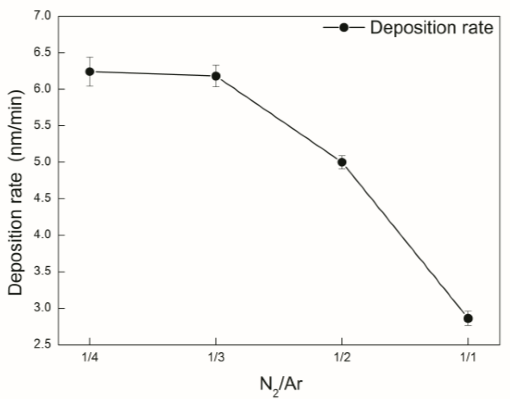
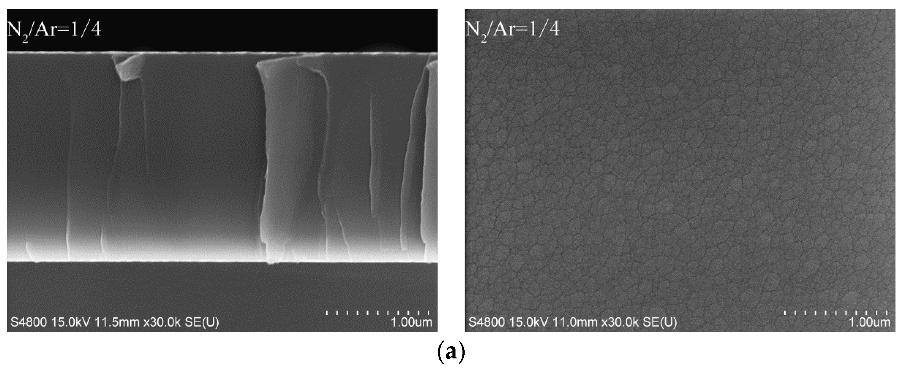
3.2. Deposition Rates and Morphologies

It can be observed in Figure 3 that the deposition rate of the coatings obviously decreased from the maximum deposition rate 6.3 nm/min to the minimum 3.3 nm/min with an increase in the N2/Ar flow ratio. Correspondingly, the coating thickness decreased from 2.04 to 0.94 μm. Target poisoning occurred, and led to more arcing discharge actions during this deposition process, due to more N2 being introduced into the reaction chamber. As a result, more nonconductive products were formed on the target surface corresponding to the decreasing effective excited target area. Jiang et al. [27] also demonstrated that the target was fully poisoned when the nitrogen-argon flow ratio was higher than 50%. Summing up, a reduced target power voltage induced by a higher nitrogen-argon flow ratio when we maintained the value of average target power (1 kW) finally gave a lower deposition rate. It’s also noted that the change of the deposition rate closely related to the average free path of the gas molecule and the sputtering rate of the target. The average free path of the sputtered particles was basically the same in this paper, due to the invariable working pressure (0.7 Pa). So, the low sputtering rate of the target should be mainly accounted for the decreasing deposition rate. Furthermore, the lower deposition rate of HiPIMS was largely related to the negative ion effects of negative high-potential cathode targets. Christie et al. [28] studied and analyzed the reasons for the low deposition rate of HiPIMS, suggesting that the sputtering metal ion with high ionization rate near the target surface was absorbed by the cathode target, thus leading to a reduction in the sputtering of metal particles.
SEM imaging (see Figure 4) clearly showed many quasicircular or elliptical nanoscale bumps uniformly distributed on the coating surface, which corresponded to the clusters of grains whose sizes decreased slightly with the increasing N2/Ar flow ratio. It can also easily be seen that the boundary of the grain cluster became clearer. In addition, AlCrSi interlayer was deposited firstly to improve the adhesion strength between the substrates and the coatings. The cross-sectional micrographs of the coatings revealed that all the coatings were well-grown adherent to the substrates and exhibited dense, homogeneous and flat nano-composite features, independent of the increasing amounts of the nitrogen. That is to say, more nitrogen incorporation into the AlCrSiN coatings had significant effects on the microstructure; namely, columnar grain growth was suppressed and the nano-composite structure was formed with a relatively slow deposition rate.
Such a smooth surface and nano-composite feature situation can be explained by the superiority of HiPIMS, but a deeper reason was the microstructure evolution in the interior coating. For one thing, with regard to the superiority of HiPIMS, the higher power density is able to generate plasma with a flux of high energetic ionized target species, which can penetrate into the sub-surface of the growing film and produce denser structures accompanied with smaller grains. Such a bombardment results in an intense atomic pinning effect at grain boundaries as a consequence, leading to a grain size reduction. Therefore, the microstructure of the coating exhibits mainly nano-composite features, due to the transformation into fine nanocrystals from columnar crystals. For another, it’s been demonstrated that the mechanism of atomic migration and grain competition in the growth mode was the result of the orientation translation of the coatings [29]. Therefore, the formed nitride, such as amorphous Si3N4, in the film was able to segregate the grain boundaries, and acted as an inhibitor for crystal and grain growth, resulting in very smooth surfaces with very fine grain sizes and more stable grain boundaries.

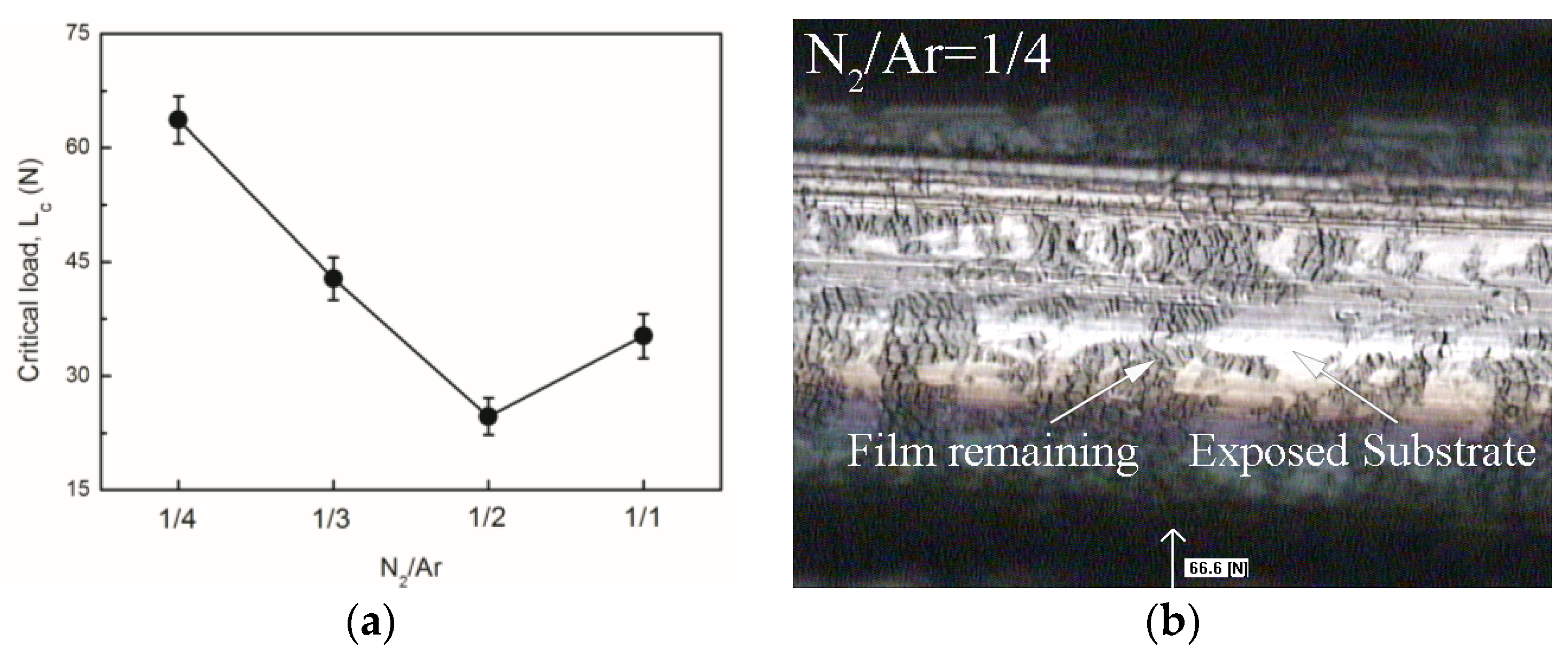
3.3. Mechanical Properties

Figure 5 shows the micro hardness (H), elastic modulus (E), and H/E, H3/E*2 (E* = E/(1 − υ2), where E* is the effective elastic modulus and υ is Poisson’s ratio values (0.28) of the AlCrSiN coatings as a function of N2/Ar flow ratio. The measured H and E values increased rapidly from 14.0 and 149.9 GPa to their highest values of 22.0 GPa and 198.3 GPa, respectively, independent of the increasing N2/Ar flow ratio. The H/E and H3/E*2 values possessed the consistent tendency with H values and the maximum H/E and H3/E*2 values of 0.10 and 0.19 GPa, respectively, were also obtained at a N2/Ar flow ratio of 1/1 of. Accordingly, the H3/E*2 ratio should be an indicator of a coating’s resistance to plastic deformation, which plays a crucial role in scratch tests and tribological tests. As shown in Figure 5, the highest H3/E*2 value of 0.19 GPa, as well as the lowest wear rate (0.81 × 10⁻¹⁴ m3/(N·m)) among the as-deposited coatings, was obtained at a N2/Ar flow ratio of 1/1. The difference in elastic deformation and recovery between the coating and the Al2O3 friction pair resulted in delamination during the wear tests. Additionally, the wear resistance of the coating could be improved by reducing the gap of the elastic deformation and the recovery. The increasing H3/E*2 ratio in this study could be attributed to the releasing of thermal stress throughout the coatings as a result of the nanocomposite structures with tolerance to the crack propagation maintaining the resistance to the plastic deformation. The test results demonstrated again that the H3/E*2 value should be one indicator for reflecting wear resistance [30].
The AlCrSiN coatings hardened with an increase in N2/Ar flow ratio, which was attributed to increasing crystallinity in the coatings. The finer AlN grain sizes and grain boundary stability induced by the forming of amorphous Si3N4 also played an important part in this hardening. The XRD pattern demonstrated the increasing crystallinity in the coatings, in consideration of the intensifying fcc-AlN peak, abrupt appearance of hcp-AlN, and broadening of all peaks (see Figure 2). The CrAlSiN coating, with a hardness of up to 27 GPa, was obtained by Ding et al. [31] by adjusting AlSi content, which demonstrated improved corrosion resistance, and excellent resistance to high-temperature oxidation at 800 °C and 1000 °C. Compared with other nanocomposite coatings, the hardness of the coating in this study was surprisingly low, which was certainly related to its relatively low crystallinity and the role of amorphous Si3N4 in the coating. Of course, the growth of nanocrystals could be promoted by subsequent heat treatment process. However, the optimization of high power-supply parameters were also very important for the deposition of nanocomposite coatings with better mechanical properties at lower temperatures, as well as higher nitrogen content atmospheres, by using HiPIMS techniques. Jiang et al. [27] also found that the hardness of AlSiN coating increased with an increase in nitrogen-argon flow ratio, and reached a maximum value of 20.6 GPa using HiPIMS techniques. Generally, the percolation of amorphous SiNx phase into the grain boundaries resulted in strong interphase boundaries and refined crystallites. Hence, the hardness of the AlCrSiN coatings was determined by this nanocomposite structure. The obvious hardening mechanisms in the as-deposited nanocrystalline coatings could be grain boundary hardening and solid solution hardening, such as the dislocation movement in the nanocrystals and the strong interface between the phases to prevent grain boundary slip. Recently, Hu et al. [32] reported that the hardness of nanograined metals depended not only on the grain size, but also on grain boundary stability. Ultrahigh hardness of nickel-molybdenum (Ni-Mo) samples was obtained by tailoring the grain boundary (GB) stability. We believe that the enhanced hardness was mainly owing to the strengthening of AlN nano-crystalline dispersion and grain boundary stability by AlN grains in SixNy phase, which indicates the hardening mechanism of the nano composite structure.
Figure 6 shows the residual stress of the AlCrSiN coatings as a function of N2/Ar flow ratio. The results indicated that increasing the nitrogen-argon flow ratios had a significant effect on the residual stress of the coating, which would be beneficial for releasing the compressed residual stress of the coatings. The residual stress of the AlCrSiN coatings decreased from −0.79 to −0.09 GPa, as the N2/Ar flow ratio changed from 1/4 to 1/1, which could be attributed to the reduction of particle kinetic energy due to the obstruction of neutral nitride particles between target and substrates, and the releasing growth stress due to the formation of a nanocomposite structure.
Specifically, the decreasing number of Ar+ resulted in a decreasing number of sputtering target ions, as well as the weakening bombardment of the deposited particles with increasing N2/Ar flow ratio. Finally, the compressive stress exhibited a decreasing trend, due to the weakening bombardment under the negative bias [33]. The formation of an amorphous Si3N4 matrix to surround nanocrystalline AlN also led to a decrease in the intrinsic stresses within the nanocomposite structure. The increasing N2/Ar flow ratio resulted in a large number of disordered amorphous Si3N4, such soft amorphous matrices kept the AlCrSiN coatings at a low compressive stress state due to the release of growth stress in the coating [34]. So, the increase of N2 flow in the vacuum chamber hindered the movement of the spurting metal ions, and resulted in the reduced ion energies of the sputtered particles. Such reduced kinetic energy of the sputtered particles allowed structural and chemical selectivity, and promoted the ordering of the defect structure. The deposited coating with low N2/Ar flow ratio possessed more highly compressed internal stress (−0.79 GPa), which can be attributed to the significant peening impact of the high-kinetic-energy sputtered particles on the previously deposited layers.
Generally, the critical load, Lc, is defined as the load used to peel off the coating during load application, which can be determined by scratch morphologies or acoustic emission signal. The critical load Lc2 corresponding to the complete peeling off of the coating (exhibited in Figure 7a) is regarded as being representative of adhesive strength between AlCrSiN coatings and SUS 304 stainless steel substrates in this study. Fracturing and delamination of the coatings can be easily observed by SEM. The largest recorded value of 66 N was obtained for the coating with 28.2 at.% N content, corresponding to a 1/4 of N2/Ar flow ratio (see in Figure 7b), due to its dense nanocomposite structure, which presented an excellent interfacial shear resistance. From micro-analysis, it could be seen that the small grains were able to slide and deflect slightly under the combined stresses, which would buffer and release the partial stresses applied to the interface [35]. From macro-analysis, the compaction effect of the deposited particles introduced compressed residual stress into the coating, and eliminated the internal defects of the coating when the particles with higher kinetic energy collided with the substrate surface. In this case, a strong adhesion was obtained due the difficulty of cracking and peeling off the coating from the substrate. In addition, it’s worth noting that the precise control of deposition process and the unique advantages of HiPIMS technology also played a crucial role in the obtained good adhesive strength.
However, a reduced trend of adhesive strength from 66 to 34.6 N with the increase of N2/Ar flow ratio can be easily observed. The above trend was attributed to the slightly increasing thickness of the AlCrSi interlayer with poorer conductivity, as well as higher brittleness. From the point of process analysis, the poorer conductivity, as well as higher brittleness, induced by the increasing thickness of AlCrSi interlayer caused the rapid reduction of particle kinetic energy under the action of negative bias. The microstructure evolution, composition variation, and phase transformation also played a crucial role. Specifically, the internal factors, such as the transformation of Al2O3 ceramic phase during the scratch test, played a key role in the sharply decreasing trend of critical load. The higher brittleness occurred when the hardness improved with increasing N2/Ar flow ratio. As a result, a reduction in the adhesion and shear failures at the interfaces occurred under the joint action of shear as well as compressive stress [13,35]. In addition, the decreased compressive stress may also have contributed to the reduction of adhesion strength, which could not effectively inhibit propagation of fatigue cracks.

3.4. Tribological Behaviors

Figure 8 shows the SEM micrographs of the AlCrSiN coatings after wear tests. It can be clearly seen that the worn surface of the low-N-content coatings (N2/Ar = 1/3, N2/Ar = 1/4) was severe, and there were large wear debris and intensive plowed grooves. Specifically, the morphology of wear track formed black wear debris separated by white plowed grooves. This undoubtedly resulted from typical severely abrasive wear. The hard and brittle particles formed in the wear track aggravated the wear between the friction pairs. We suspect that the local high temperature generated in sliding resulted in the formation of ceramic alumina phase in the coating, which plays a major role as an abrasive in the formation of ribbon-like grooves. The lower surface hardness also affected the frictional behavior. We observed two main areas in the surface coating: wear track and AlCrSiN film (Figure 8). The morphology of the wear track became relatively smoother, and little ribbon-like micro-scars without apparent cracks corresponding to the high-N-content coatings (N2/Ar = 1/2, N2/Ar = 1/1).
However, relatively shallow black wear tracks could be found from the above morphologies. This meant that adhesive wear of the coating had occurred, which corresponded to the low wear rate of the high-N-content coatings (N2/Ar = 1/2, N2/Ar = 1/1). The adhesive wear resulted from micro-junctions caused by welding between the friction pairs. In this case, serious wear occurred on the surface of the Al2O3 ball, and parts of the black wear debris had adhered to the surface of the coating, thereby reducing the abrasion of the coating. This caused a lower wear rate than abrasive wear for coatings.
Figure 9a presents the graph of average friction coefficient (COF) changes obtained during wear tests in relation to counterpart with Al2O3 ball at room temperature. The COFs at RT were very similar to those measured by Georgiadis et al. [36]. Initially, the friction pairs were in the running-in state, and the friction coefficients increased rapidly, which is often attributed to the interaction between the surface oxide layer and the Al2O3 ball. Then, after some time, a relatively steady state was reached, which represented the friction within the coating. The increasing N2/Ar flow ratio in the AlCrSiN coatings resulted in an increase in the average friction coefficient from 0.68 to 0.85, which was attributed to the improved coating hardness and the tribo-chemical reaction occurring at the friction interfaces. The friction coefficient curves of the coatings with low N content (<34.4 at.%, N2/Ar = 1/3, N2/Ar = 1/4) exhibited significant fluctuations, which was attributed to the strength of the formed tribolayer in the wear track being insufficient, so that it was periodically worn out [12]. Consequently, abrasive particles were involved in the interfacial contact area between the coating and the counterpart as third-body abrasives. The hard debris worn off from the coating surface scratched the friction interface, forming some distinct micro ploughs (see Figure 9a). Similar results were reported in Reference [13,37]. Finally, the main wear mechanisms of the low-N-content coatings became abrasive wear accompanied by plastic deformation.
However, the friction coefficient curves of the coatings with high N content (>45.5 at.%, N2/Ar = 1/2, N2/Ar = 1/1) exhibited smoothness, and possessed higher average friction coefficient values, which was attributed to the enhancement of coating hardness and severe wear of the Al2O3 ball. The COF values of the coating deposited at a N2/Ar flow ratio of 1/1 was a little lower than the coating deposited at a N2/Ar flow ratio of 2/1; this phenomenon resulted from its higher hardness, and the decreased interfacial contact area between Al2O3 ball and the coating surface. Wear debris from the Al2O3 ball bonded to the friction interface, reducing wear on the coating. So the main wear mechanism of the high-N-content AlCrSiN coatings could be adhesive wear, as well as plastic deformation.
All the as-deposited AlCrSiN coatings exhibited obvious changes of wear tracks, and high friction coefficients ranging in 0.68–0.85. The results indicated that varying the N2/Ar volume flow ratio had a significant influence on both the friction coefficient and the wear rates. It was noted that high H/E and H3/E*2 values meant larger elastic strain to failure and higher fracture toughness, and led to better wear resistance [24,25]. Correspondingly, the coatings with high N content (N2/Ar = 1/1) possessed higher H/E values and H3/E*2 (0.10, 0.19 GPa) and performed better in terms of wear resistance. The lowest wear rate of 0.81 × 10⁻¹⁴ m3/(N·m) was noted for the AlCrSiN coating with the highest N content at a sliding distance of 75 m, which was almost thirty four times lower than that of the coating with lowest N content and a wear rate of 2.8 × 10⁻¹³ m3/(N·m) (see Figure 9b). The results indicated that the coatings with adequate friction coefficient while having the highest H3/E*2 value exhibited a superior wear resistance among all the AlCrSiN coatings. Zhou et al. [38] reported that the lowest wear rates of the AlTiCrN coatings was approximately 2.7 × 10⁻¹⁶ m3/(N·m) at 600 °C. Therefore, the focus of our next work will be to verify the high-temperature friction properties of AlCrSiN coatings.

4. Conclusions

  • With increasing the N2/Ar flow ratio, the nanocrystals in AlCrSiN coatings evolved gradually from a metastable solid-solution fcc-(Cr,Al)N phase to the mixture of fcc-(Cr,Al)N and hcp-(Cr,Al)N.
  • The increasing of the N2/Ar flow ratio resulted in increasing crystallinity in the coating, and finally produced an increase both in the hardness and the elastic modulus of the AlCrSiN coatings due to the microstructure evolution and composition variation.
  • The increase of the N2/Ar flow ratio also resulted in an increment of the average friction coefficient and wear resistance. The main wear mechanism gradually changed from serious abrasive wear and plastic deformation to slight adhesive wear with increasing N content in the as-deposited AlCrSiN coatings. And the AlCrSiN coatings with the highest N content (56.3 at.%, N2/Ar = 1/1) possessed a superior wear resistance.

Acknowledgments

This work was supported by the National Nature Science Foundation of China (51301181 and 41406092), Tianjin Key Research Program of Application Foundation and Advanced Technology (Grant No. 15JCZDJC39700), Tianjin Science and Technology correspondent project (16JCTPJC51400), Innovation Team Training Plan of Tianjin Universities and colleges (Grant No. TD12-5043).

Author Contributions

Tie-Gang Wang and Bai-Song Li conceived and designed the experiments; Bai-Song Li performed the experiments; Jicheng Ding and Jing Shi analyzed the data; Yujun Cai and Xitong Zhang contributed reagents/materials/analysis tools; Bai-Song Li wrote parts of the paper.

Conflicts of Interest

The authors declare no conflict of interest.

References

  1. Lin, J.L.; Zhang, N.Y.; Sproul, W.D.; Moore, J.J. Comparison of the oxidation behavior of CrN flms deposited using continuous dc pulsed dc and modulated pulsed power magnetron sputtering. Surf. Coat. Technol. 2012, 206, 3283–3290. [Google Scholar] [CrossRef]
  2. Wu, D.; Jiang, S.; Fan, Q.; Gong, J.; Sun, C. Hot corrosion behavior of a Cr-modified aluminide coating on a Ni-based superalloy. Acta Metall. Sin. 2014, 27, 627–634. [Google Scholar] [CrossRef]
  3. Zhang, S.; Wang, L.; Wang, Q.; Li, M. A superhard CrAlSiN superlattice coating deposited by a multi-arc ion plating: II. Thermal stability and oxidation resistance. Surf. Coat. Technol. 2013, 214, 153–159. [Google Scholar] [CrossRef]
  4. Xiao, B.J.; Li, H.X.; Mei, H.J. A study of oxidation behavior of AlTiN-and AlCrN-based multilayer coatings. Surf. Coat. Technol. 2018, 333, 229–237. [Google Scholar] [CrossRef]
  5. Bobzin, K.; Brögelmann, T.; Brugnara, R.H. Aluminum-rich HPPMS (Cr1−xAlx)N coatings deposited with different target compositions and at various pulse lengths. Vacuum 2015, 122, 201–207. [Google Scholar] [CrossRef]
  6. Polcar, T.; Cavaleiro, A. Review on self-lubricant transition metal dichalcogenide nanocomposite coatings alloyed with carbon. Mater. Chem. Phys. 2011, 129, 195–201. [Google Scholar] [CrossRef]
  7. Lewin, E.; Loch, D.; Montagne, A.; Ehiasarian, A.P.; Patscheider, J. Comparison of Al-Si-N nanocomposite coatings deposited by HIPIMS and DC magnetron sputtering. Surf. Coat. Technol. 2013, 232, 680–689. [Google Scholar] [CrossRef]
  8. Wu, W.; Chen, W.; Yang, S.; Lin, Y.; Zhang, S.; Cho, T.-Y.; Lee, G.H.; Kwon, S.-C. Design of AlCrSiN multilayers and nanocomposite coating for HSS cutting tools. Appl. Surf. Sci. 2015, 351, 803–810. [Google Scholar] [CrossRef]
  9. Chang, C.-C.; Chen, H.-W.; Lee, J.-W.; Duh, J.-G. Influence of Si contents on tribological characteristics of CrAlSiN nanocomposite coatings. Thin Solid Films 2015, 584, 46–51. [Google Scholar] [CrossRef]
  10. Chang, C.-C.; Chen, H.-W.; Lee, J.-W.; Duh, J.-G. Development of Si-modified CrAlSiN nanocomposite coating for anti-wear application in extreme environment. Surf. Coat. Technol. 2015, 284, 273–280. [Google Scholar] [CrossRef]
  11. Kuo, Y.-C.; Wang, C.-J.; Lee, J.-W. The microstructure and mechanical properties evaluation of CrTiAlSiN coatings: Effects of silicon content. Thin Solid Films 2017, 638, 220–229. [Google Scholar] [CrossRef]
  12. Sun, S.; Ye, Y.; Wang, Y.; Liu, Q.; Liu, X.; Li, J.; Wang, L. Structure and tribological performances of CrAlSiN coatings with different Si percentages in seawater. Tribol. Int. 2017, 115, 591–599. [Google Scholar] [CrossRef]
  13. Wang, T.-G.; Dong, Y.; Gebrekidan, B.A.; Liu, Y.-M.; Fan, Q.-X.; Kim, K.H. Microstructure and Properties of the Cr-Si-N Coatings Deposited by Combining High-Power Impulse Magnetron Sputtering (HiPIMS) and Pulsed DC Magnetron Sputtering. Acta Metall. Sin. 2017, 30, 688–696. [Google Scholar] [CrossRef]
  14. Chen, M.; Chen, W.; Cai, F.; Zhang, S.; Wang, Q. Structural evolution and electrochemical behaviors of multilayer Al-Cr-Si-N coatings. Surf. Coat. Technol. 2016, 296, 33–39. [Google Scholar] [CrossRef]
  15. Geng, D.; Li, H.; Zhang, Q.; Wang, C.; Wu, Z.; Wang, Q. Effect of incorporating oxygen on microstructure and mechanical properties of AlCrSiON coatings deposited by arc ion plating. Surf. Coat. Technol. 2017, 310, 223–230. [Google Scholar] [CrossRef]
  16. Bobzin, K.; Brögelmann, T.; Kalscheuer, C.; Naderi, M. Hybrid dcMS/HPPMS PVD nitride and oxynitride hard coatings for adhesion and abrasion reduction in plastics processing. Surf. Coat. Technol. 2016, 308, 349–359. [Google Scholar] [CrossRef]
  17. Bobzin, K.; Brögelmanna, T.; Grundmeier, G.; de los Arcos, T.; Wiesing, M.; Kruppe, N.C. (Cr,Al)N/(Cr,Al)ON Oxy-nitride Coatings deposited by Hybrid dcMS/HPPMS for Plastics Processing Applications. Surf. Coat. Technol. 2016, 308, 394–403. [Google Scholar] [CrossRef]
  18. Yang, Y.-C.; Chang, C.-T.; Hsiao, Y.-C.; Lee, J.-W.; Lou, B.-S. Influence of high power impulse magnetron sputtering pulse parameters on the properties of aluminum nitride coatings. Surf. Coat. Technol. 2014, 259, 219–231. [Google Scholar] [CrossRef]
  19. Veprek, S.; Zhang, R.F.; Veprek-Heijman, M.G.J.; Sheng, S.H.; Argon, A.S. Superhard nanocomposites: Origin of hardness enhancement, properties and applications. Surf. Coat. Technol. 2010, 204, 1898–1906. [Google Scholar] [CrossRef]
  20. Veprek, S.; Veprek-Heijman, M.G.J. Industrial applications of superhard nanocomposite coatings. Surf. Coat. Technol. 2008, 202, 5063–5073. [Google Scholar] [CrossRef]
  21. Cao, F.; Munroe, P.; Zhou, Z.; Xie, Z. Mechanically robust TiAlSiN coatings prepared by pulsed-DC magnetron sputtering system: Scratch response and tribological performance. Thin Solid Films 2018, 645, 222–230. [Google Scholar] [CrossRef]
  22. Wang, T.; Zhang, G.; Ren, S.; Jiang, B. Effect of nitrogen flow rate on structure and properties of MoNx coatings deposited by facing target sputtering. J. Alloys Compd. 2017, 701, 1–8. [Google Scholar] [CrossRef]
  23. Bobzin, K.; Bagcivan, N.; Immich, P.; Bolz, S.; Alami, J.; Cremer, R. Advantages of nanocomposite coatings deposited by high power pulse magnetron sputtering technology. Mater. Process. Technol. 2009, 209, 165–170. [Google Scholar] [CrossRef]
  24. Qi, D.; Lei, H.; Wang, T.; Pei, Z.; Gong, J.; Sun, C. Mechanical, microstructural and tribological properties of reactive magnetron sputtered Cr-Mo-N films. J. Mater. Sci. Technol. 2015, 31, 55–64. [Google Scholar] [CrossRef]
  25. Georgiadis, A.; Gautier, G.; Cartasegna, F. AlSiTiN and AlSiCrN multilayer coatings: Effects of structure and surface composition on tribological behavior under dry and lubricated conditions. Appl. Surf. Sci. 2016, 365, 218–226. [Google Scholar]
  26. Wang, T.; Zhao, S.; Hua, W.; Li, J.; Gong, J.; Sun, C. Estimation of residual stress and its effects on the mechanical properties of detonation gun sprayed WC-Co coatings. Mater. Sci. Eng. A 2010, 527, 454–461. [Google Scholar] [CrossRef]
  27. Jiang, X.; Yang, F.; Chen, W.; Lee, J.-W.; Chang, C. Effect of nitrogen-argon flow ratio on the microstructural and mechanical properties of AlSiN thin films prepared by high power impulse magnetron sputtering. Surf. Coat. Technol. 2017, 320, 138–145. [Google Scholar] [CrossRef]
  28. Christie, D.J. Target material pathways model for high power pulsed magnetron sputtering. J. Vac. Sci. Technol. A 2005, 23, 330–335. [Google Scholar] [CrossRef]
  29. Soucek, P.; Daniel, J.; Hnilica, J.; Bernatova, K.; Zabransky, L.; Bursıkova, V.; Stupavska, M.; Vasina, P. Superhard nanocomposite nc-TiC/a-C:H coatings: The effect of HiPIMS on coating microstructure and mechanical properties. Surf. Coat. Technol. 2017, 311, 257–267. [Google Scholar] [CrossRef]
  30. Kim, H.K.; La, J.H.; Kim, K.S.; Lee, S.Y. The effects of the H/E ratio of various Cr-N interlayers on the adhesion strength of CrZrN coatings on tungsten carbide substrates. Surf. Coat. Technol. 2015, 284, 230–234. [Google Scholar] [CrossRef]
  31. Ding, J.; Zhang, T.; Yun, J. Microstructure, Mechanical, Oxidation and Corrosion Properties of the Cr-Al-Si-N Coatings Deposited by a Hybrid Sputtering System. Coatings 2017, 7, 119. [Google Scholar] [CrossRef]
  32. Hu, J.; Shi, Y.N.; Sauvage, X.; Sha, G.; Lu, K. Grain boundary stability governs hardening and softening in extremely fine nanograined metals. Science 2017, 355, 1292–1296. [Google Scholar] [CrossRef] [PubMed]
  33. Wang, T.-G.; Jeong, D.; Kim, S.-H.; Wang, Q.; Shin, D.-W.; Melin, S.; Iyengar, S.; Kim, K.H. Study on nanocrystalline Cr2O3 films deposited by arc ion plating: I. composition, morphology, and microstructure analysis. Surf. Coat. Technol. 2012, 206, 2629–2637. [Google Scholar] [CrossRef]
  34. Bansal, P.; Shipway, P.H.; Leen, S.B. Residual stresses in high-velocity oxy-fuel thermally sprayed coatings—Modelling the effect of particle velocity and temperature during the spraying process. Acta Mater. 2007, 55, 5089–5101. [Google Scholar] [CrossRef]
  35. Burnett, P.J.; Rickerby, D.S. The relationship between hardness and scratch adhession. Thin Solid Films 1987, 154, 403–416. [Google Scholar] [CrossRef]
  36. Georgiadis, A.; Fuentes, G.G.; Almandoz, E.; Medrano, A.; Palacio, J.F.; Miguel, A. Characterisation of cathodic arc evaporated CrTiAlN coatings: Tribological response at room temperature and at 400 °C. Mater. Chem. Phys. 2017, 190, 194–201. [Google Scholar] [CrossRef]
  37. Chen, S.; Luo, D.; Zhao, G. Investigation of the properties of TixCr1−xN coatings prepared by cathodic arc deposition. Phys. Procedia 2013, 50, 163–168. [Google Scholar] [CrossRef]
  38. Zhou, H.; Zheng, J.; Gui, B.; Geng, D.; Wang, Q. AlTiCrN coatings deposited by hybrid HiPIMS/DC magnetronco-sputtering. Vacuum 2017, 136, 129–136. [Google Scholar] [CrossRef]
Figure 1. Chemical composition of the AlCrSiN coatings as a function of N2/Ar flow ratio.
Coatings 08 00003 g001
Figure 2. X-ray diffraction patterns of the AlCrSiN coatings with different N2/Ar flow ratio.
Coatings 08 00003 g002
Figure 3. Deposition rate of the AlCrSiN coatings as a function of N2/Ar flow ratio.
Coatings 08 00003 g003
Figure 4. SEM cross-sectional and corresponding surface images of Al-Cr-Si-N coatings as a function of N2/Ar flow ratio: (a) N2/Ar = 1/4; (b) N2/Ar = 1/3; (c) N2/Ar = 1/2; (d) N2/Ar = 1/1.
Coatings 08 00003 g004aCoatings 08 00003 g004b
Figure 5. (a) Micro-hardness, elastic modulus and H/E and H3/E*2 values of the Al-Cr-Si-N films as a function of N2/Ar flow ratio hardness and elastic modulus of coatings; (b) H/E ratio and H3/E*2 values of coatings.
Coatings 08 00003 g005
Figure 6. The residual stress of the AlCrSiN coatings as a function of N2/Ar flow ratio.
Coatings 08 00003 g006
Figure 7. The critical load and the scratch morphology of the AlCrSiN coatings as a function of N2/Ar flow ratio: (a) Critical load of coatings; (b) Scratch morphology of coatings.
Coatings 08 00003 g007
Figure 8. The wear morphology of the AlCrSiN coatings as a function of N2/Ar flow ratio: (a) N2/Ar = 1/4; (b) N2/Ar = 1/3; (c) N2/Ar = 1/2; (d) N2/Ar = 1/1.
Coatings 08 00003 g008
Figure 9. The friction coefficient and the wear rate of the AlCrSiN coatings as a function of N2/Ar flow rate: (a) friction coefficient of coatings; (b) wear rate of coatings.
Coatings 08 00003 g009
Table 1. Detailed deposition parameters of the Al-Cr-Si-N coatings deposited by HiPIMS.
ParameterValue
Base pressure/Pa2.0 × 10−3
Working pressure/Pa7.0 × 10−1
Bias voltage/V−30
N2/Ar flow ratio (sccm)1/4 (N2: 28, Ar: 112); 1/3 (N2: 35, Ar: 105); 1/2 (N2: 47, Ar: 94); 1/1 (N2: 70, Ar: 70)
Deposition temperature/°C300
HiPIMS average sputtering power/kW1.0
HiPIMS average sputtering voltage/V~555
HiPIMS pulse width/μs160
HiPIMS frequency/Hz180
Substrate rotation speed/r·min−12
Distance between target and substrate/mm100
Deposition time/min330

