Preparation and Characterization of Sprayed-Yttrium Oxyfluoride Corrosion Protective Coating for Plasma Process Chambers


1
Department of Materials Science and Engineering, National Chung Hsing University, Taiching 40227, Taiwan
2
Department of Industrial Engineering and Management, Da-Yeh University, Changhua 51591, Taiwan
3
Department of Materials Science and Engineering, Da-Yeh University, Changhua 51591, Taiwan
*
Author to whom correspondence should be addressed.
Coatings 2018, 8(10), 373; https://doi.org/10.3390/coatings8100373
Submission received: 25 September 2018
/
Revised: 11 October 2018
/
Accepted: 20 October 2018
/
Published: 22 October 2018
Abstract
:This study investigates the microstructure, mechanical and electrical properties of dense yttrium oxyfluoride (YOF) coatings fabricated by the atmospheric plasma spraying technique. Transmission electron microscopy and X-ray diffraction analysis revealed a well crystallized YOF coating with preferred orientations. The YOF coatings were more porous (approximate porosity 0.5%), with higher hardness (290 ± 30 HV), lower electrical resistivity (1016 Ω⋅cm), and breakdown voltage (5.57 kV), than conventional yttrium-fluoride plasma-protective coating. These results indicate the potential of the YOF coating as a novel antiplasma and corrosion-resistant ceramic.
1. Introduction
Integrated circuit (IC) technology incorporates various features on single electrical chips [1]. The increasing miniaturization of modern ICs has promoted the use of high-density plasma irradiation for silicon wafer processing. However, contaminants generated by the semiconductor plasma processing equipment pose a serious problem in the mass production of ICs [2]. Contaminant particles are formed when corrosive fluorocarbon gases (such as CF4, CHF3, C4F6, and C2F6) bombard and react with the inner wall and inner parts of the chamber, degrading the process reproducibility, causing leakage current in the ICs, and lowering the production yield [3,4]. Particle formation during etching or deposition is usually prevented by silicon-based ceramics, which are advantaged by their high hardness, high wear resistance, dielectric strength, and chemical stability [5,6]. However, particle contaminants from silicon-based materials are known to react with the fluorine plasma, generating tungsten silicide and polycrystalline silicon [7,8,9].
Aluminum oxide (Al2O3) and yttrium oxide (Y2O3), with higher plasma-erosion resistance than conventional silicon-based materials, have been adopted as the plasma-facing inner wall materials in the plasma processing equipment of IC production [10,11,12]. Unfortunately, the inner-wall Y2O3 coating reacts with the plasma to produce fluorine-containing particles [13]. The resulting erosion releases particles that contaminate the wafer.
Substituting the Y2O3 and Al2O3 ceramic materials with yttrium fluoride (YF3) is expected to resolve this problem [14,15]. YF3 reportedly has a high dielectric strength and YF3 coating exhibits a higher plasma-erosion resistance than Y2O3 coating. Moreover, the standard enthalpy of the metal–oxygen bond is lower in oxidized YF3 coating (−392 kJ·mol−1) than in Y2O3 coating (−318 kJ·mol−1), indicating that YF3 is more chemically stable than Y2O3. Yttrium oxyfluoride (YOF) was recently detected on a YF3 coating exposed to fluorocarbon plasma. The oxidized YF3 effectively suppressed the particle generation [16] (and reference therein), suggesting that YOF coating is a suitable plasma-facing material in plasma processing equipment. Therefore, the present study compares the characteristics of YOF and YF3 coatings fabricated by atmospheric plasma spraying (APS). By evaluating the microstructure, dielectric, and mechanical properties of the YOF and YF3 coatings, we evaluated their potentials as protective materials in plasma processing equipment.
2. Materials and Methods
The spraying materials were commercially pure YOF powders (25–50 μm, 99.99%, Shin-Etsu Chemical, Tokyo, Japan) and YF3 powders (25–50 μm, 99.99%, Shin-Etsu Chemical, Tokyo, Japan). The YOF and YF3 coatings were fabricated by APS with an F4-MB plasma gun (Oerlikon Metco, Pfäffikon, Switzerland). Prior to APS, the alloy aluminum (A6061) substrate (of area and thickness 400 mm2 and 20 mm, respectively) was sandblasted with SiO2 and cleaned in acetone. The stand-off distance was adjusted to 10 cm. The Ar and H2 gas cylinders were opened by initiating the air compressor (HAUG, St. Gallen, Switzerland). The Ar and H2 flow rates, system voltage, gun movement rate, and feed rate were set to 45 L/min, 6 L/min, 50 V, 10 cm/s, and 15 g/min, respectively. Previously, we reported uniform plasma spreading at 15 kW; therefore we set the plasma power to 15 kW in the following work [17].
The YOF and YF3 spraying parameters are shown in Table 1. The surface morphology, microstructure, and elemental analysis of the coating samples were conducted using scanning electron microscopy (SEM, S-3000H, Hitachi, Tokyo, Japan), energy dispersive X-ray diffraction (EDX, Bruker Nano GmbH, Berlin, Germany), and transmission electron microcopy (TEM, H-600, Hitachi, Tokyo, Japan). The sample compositions were examined by X-ray photoelectron spectroscopy (XPS, PHI 5000 VersaProbe, ULVAC-PHI, Kanagawa, Japan) using a monochromatic Al Kα X-ray source at a passing energy of 20 eV with a spot size of 650 μm. The chemical-composition depth profile of the sample was obtained by etching the surface with focused argon-ion sputtering (Thermo Fisher Scientific K-Alpha, East Grinstead, UK). To estimate the contributions of bonding with fluorine elements, the photoelectron spectrum resulting from the core energy levels of Yttrium 3d states was deconvoluted by a fitting software program (Thermo Fisher Scientific, Waltham, MA, USA). The porosity of the coating was evaluated from the optical image by metallographic optical microscope. The bond strengths of the samples were measured in a pulling test (Cytec Fiberite FM1000, Havre de Grace, MD, USA) according to the ASTM D412-98a standard [18]. The Vickers microhardness was estimated using the Vickers indentation method based on ASTM C1327-99 [19]. The dielectric voltage was measured following the standard protocol of ASTM D419-09 [20].
3. Results and Discussion
Figure 1a,b show the surface and a cross-sectional SEM image, respectively, of the YOF coating sprayed at a plasma power of 15 kW. The surface microstructure exhibits fully molten granules and relatively flat morphologies (Figure 1a). The YOF coating layers (average thickness = 200 μm) are dense with very poor porosity (Figure 1b). Because the thermal expansions of the YOF coating (14.1 × 10⁻⁶/K) and Al substrate (23 × 10−6/K) are very similar, no cracks were observed in the YOF sample. These results indicate a better crystalline and denser microstructure of the YOF than the YF3 coating sample. Density defects density such as pores, cavities and cracks significantly affect the antiplasma-erosion resistance of the material [21]. Hence, the YOF coating is eminently applicable to plasma equipment.
Figure 2 shows typical XRD patterns of the YOF sample coated under a plasma power of 15 kW. The highest diffraction peaks in Figure 2a are assignable to the (012) and (110) planes of a stable rhombohedral phase, and are exactly matched to the JCPD data (No. 71-2100) [22]. In Figure 2b, the XRD results show the (020) plane of the orthorhombic YF3 phase and the (400) plane of the cubic Y2O3 phase, which is in agreement with the JCPD data (No. 74-0911) [17].
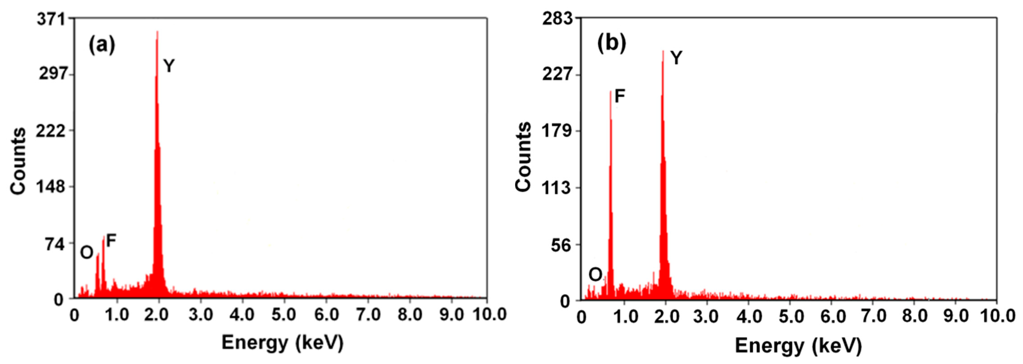
The compositions of the two coating samples were determined by EDX. The EDX spectra are shown in Figure 3, and the obtained data are included in Table 2. In Figure 3a, The F, Y, and O contents in the YOF coating are 26.02 at.%, 36.01 at.%, and 25.27 at.%, respectively, confirming that YOF was the major phase in the samples. The YF3 coating contained mainly F and Y atoms (64.62 at.% and 27.01 at.%, respectively), with minor amounts of oxygen (3.93 at.%; see Figure 3b). As discussed above, the YOF coating contained oxygen and fluorine elements, and both the oxide and fluoride materials were chemically stable during the plasma etching/deposition process [23].
The crystal structure of these coatings was revealed by TEM. Figure 4 show cross-sectional TEM micrographs of the YOF and YF3 coatings, respectively. The insets show the selected area electron diffraction (SAED) patterns of the two coating samples, which reveal their crystallographic relationships. The regularly arranged diffraction rings in the SAED patterns suggest a polycrystalline structure for both coatings, consistent with the XRD result. In the inset of Figure 4a, the diffraction rings derive from the (012) and (110) crystal facets, consistent with the rhombohedral phase of the YOF structure. In the inset of Figure 4b, they derive from the (111) and (012) crystal facets, consistent with the orthorhombic phase of the YF3 structure.
The calculated porosity volume fractions of the YF3 and Y2O3 coatings obtained at various plasma-spray powers are shown in Figure 5. The YOF and YF3 coatings were least porous (1.0% and 0.5%, respectively) under a plasma-spray power of 21 kW. Therefore, the YOF and YF3 coatings at this power were very dense, as observed in the SEM morphologies [17]. Note that the porosity was 0.5%–1.0% lower in the YOF coating than in the YF3 coating. As the plasma power increases, the granule velocity and deposition temperature also increase. These increases might explain the decreased porosity with better interface bonding under higher plasma powers [24].
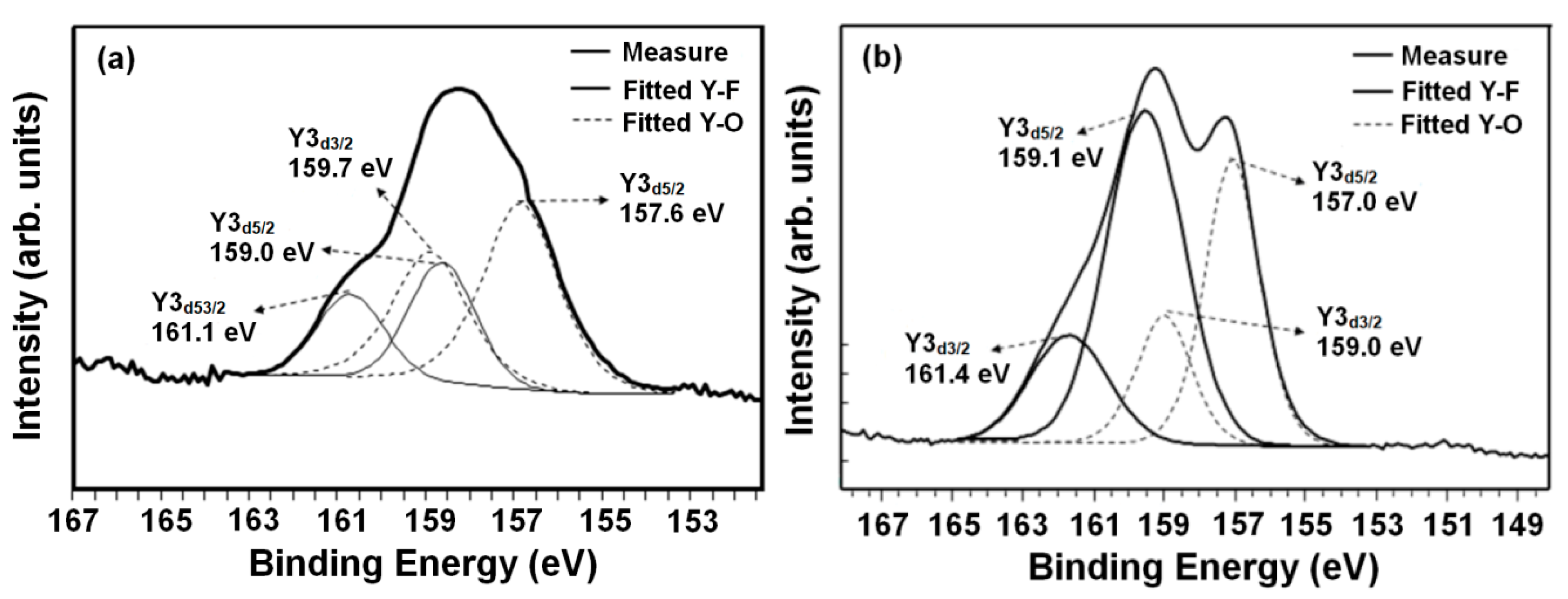
Figure 6 presents the Y3d XPS spectra of the YOF and YF3 coating samples. The curve-fitted YOF XPS spectrum deconvolutes into four peaks (Figure 6a). The Y3d splits into two peaks (Y3d5/2 and Y3d3/2), implying two bonding sources of the cations. The intensity ratio and peak shift in binding energy (~3:2 and 2 eV, respectively), in accord with the XPS data reported in the literature [25]. The peaks at higher binding energy (159 and 161.1 eV) are attributable to the Y–F bonds in the YOF coating sample, whereas the lower peaks (at 157 and 159 eV) correspond to the Y–O bonds. The energy difference is due to the higher electronegativity of fluorine (4.0) than of oxygen (3.5) [26]. The XPS spectrum of the YF3 coating also exhibits two doublets (Figure 6b), one representing the high binding energy of the Y–F bonds (peaking at 159 and 161.1 eV), the other corresponding to the low binding energy of the Y–O bonds (peaking at 157.6 and 159.7 eV). As clarified in the TEM observations, the oxyflouride layer protects the coating of the chamber sidewall from further erosion by the fluorocarbon plasma, thereby reducing the particle contamination [16]. Therefore, it is believed that the YOF coating is more chemically stable to CF4/O2 plasma than the YF3 coating.
To meet the plasma resistance requirements, the YOF coating must also exhibit appropriate mechanical and electrical properties. The properties of YOF and YF3 are compared in Table 3. The Vickers’ hardness values of the YOF and YF3 coatings were estimated as 260–320 and 235–285 HV, respectively. The YOF coating is harder than other yttrium-based plasma-resistant materials (YF3 and Y2O3) [17]. The microstructure, residual stress, grain size and crystal phase configuration significantly affects the hardness of oxide ceramics [27]. The higher hardness in the YOF coating might be attributed to the larger number of Y–O bonds and higher bond strength in YOF than in YF3. Meanwhile, YOF with its high concentration of oxygen vacancies can maintain its hardness under operation at high ambient temperatures. The dense microstructure of YOF also contributes to its hardness value.
The adhesion strengths of the YOF and YF3 coatings were 7.35 and 8.56 MPa, respectively. This result, which is consistent with the XPS results, might reflect the different types of chemical bonds in the YOF and YF3 coatings. The dielectric strengths of the YOF and YF3 coatings were 24.67 and 22.65 kV/mm, respectively. However, the dielectric strength rapidly decreases with increasing porosity [28]. Therefore, the higher dielectric strength of the YOF than the YF3 coating can be explained by the dense crystalline structure and low film porosity of the former, as mentioned in the SEM results. This means that the YOF coating prevents electron conductivity during high-voltage operation. Furthermore, the YOF coating exhibited superior insulating capability, with an electrical resistivity of 1 × 10¹⁶ Ω·cm and a breakdown voltage of 5.57 kV, implying that YOF is an effective material for insulating applications. Moreover, owing to their large electrical resistivity and high corrosion resistance, YOF coatings meet the requirements of ceramic electrostatic chucks [29,30] (Coulomb type: Electrical resistivity > 1014 Ω·cm, Johnsen–Rahbek type: Electrical resistivity > 1010 Ω·cm). Overall, the mechanical and thermal properties of YOF coating are higher than those of the YF3 coating.
4. Conclusions
A dense, low-porosity (0.5%–1.0%) YOF coating was deposited on an Al substrate by the APS method. The mechanical and electrical properties of the YOF coating were excellent, and comparable to those of YF3. These results demonstrated that YOF is a promising material for the inner walls and electrostatic chucks, and will be expected to prevent the particle contaminations of mass-production semiconductor-plasma processing equipment.
Author Contributions
Conceptualization, W.-K.W.; Methodology, T.-K.L., D.-S.W., S.-Y.H. and W.-K.W.; Data Curation, T.-K.L., D.-S.W. and W.-K.W.; Writing—Original Draft Preparation, T.-K.L., D.-S.W. and S.-Y.H.; Writing—Review and Editing, D.-S.W. and W.-K.W.
Funding
This research was funded by the Ministry of Science and Technology of Taiwan (No. 107-2221-E-212-004).
Acknowledgments
The authors wish to express their sincere gratitude for the technical support from the advanced Industry Technology Centre of National Chung Hsing University, Taiwan.
Conflicts of Interest
The authors declare no conflict of interest.
References
- Hou, S.Y.; Chen, W.C.; Hu, C.; Chiu, C.; Ting, K.C.; Lin, T.S.; Wei, W.H.; Chiou, W.C.; Lin, V.J.C.; Chang, V.C.Y.; et al. Wafer-level integration of an advanced logic-memory system through the second-generation CoWoS technology. IEEE Trans. Electron. Devices 2017, 64, 4071–4077. [Google Scholar] [CrossRef]
- Ito, N.; Moriya, T.; Uesugi, F.; Matsumoto, M.; Liu, S.; Kitayama, Y. Reduction of particle contamination in plasma-etching equipment by dehydration of chamber wall. Jpn. J. Appl. Phys. 2008, 47, 3630–3634. [Google Scholar] [CrossRef]
- Yoo, S.W.; Hwang, N.M.; You, S.J.; Kim, J.H.; Seong, D.J. Control of nanoparticle size and amount by using the mesh grid and applying DC-bias to the substrate in silane ICP-CVD process. J. Nanopart. Res. 2017, 19, 374. [Google Scholar] [CrossRef]
- Sato, N.; Uchida, G.; Kaneko, T.; Shimizu, S.; Iizuka, S. Dynamics of fine particles in magnetized plasmas. Phys. Plasmas 2001, 8, 1786–1790. [Google Scholar] [CrossRef]
- Kim, D.M.; Kim, K.B.; Yoon, S.Y.; Oh, S.Y.; Kim, H.T.; Lee, S.M. Effects of artificial pores and purity on the erosion behaviors of polycrystalline Al2O3 ceramics under fluorine plasma. J. Ceram. Soc. 2009, 117, 863–867. [Google Scholar] [CrossRef]
- Lim, K.Y.; Kim, W.Y.; Kim, K.J. Mechanical properties of electrically conductive silicon carbide ceramics. Ceram. Int. 2014, 40, 10577–10582. [Google Scholar] [CrossRef]
- Lim, K.Y.; Blain, M.G.; Tipton, G.D.; Holber, W.M.; Selwyn, G.S.; Westerfield, P.L.; Maxwell, K.L. Particle behavior in an electron cyclotron resonance plasma etch tool. Plasma Source Sci. Technol. 1994, 3, 325–333. [Google Scholar]
- Fukumoto, H.; Fujikake, I.; Takao, Y.; Takao, K.; Ono, K. Plasma chemical behaviour of reactants and reaction products during inductively coupled CF4 plasma etching of SiO2. Plasma Sources Sci. Technol. 2009, 18, 045027. [Google Scholar] [CrossRef]
- Tezani, L.L.; Pessoa, R.S.; Maciel, H.S.; Petraconi, G. Chemistry studies of SF6/CF4, SF6/O2 and CF4/O2 gas phase during hollow cathode reactive ion etching plasma. Vacuum 2014, 106, 64–68. [Google Scholar] [CrossRef]
- Kim, D.P.; Yeo, J.W.; Kim, C.I. Etching properties of Al2O3 films in inductively coupled plasma. Thin Solid Films 2004, 459, 122–126. [Google Scholar] [CrossRef]
- Miwa, K.; Takada, N.; Sasaki, K. Fluorination mechanisms of Al2O3 and Y2O3 surfaces irradiated by high-density CF4/O2 and SF6/O2 plasma. J. Vac. Sci. Technol. A 2009, 27, 831–835. [Google Scholar] [CrossRef]
- Cao, Y.C.; Zhao, L.; Luo, J.; Wang, K.; Zhang, B.P.; Yokota, H.; Ito, Y.; Li, J.F. Plasma etching behavior of Y2O3 ceramics: Comparative study with Al2O3. Appl. Sur. Sci. 2016, 366, 304–309. [Google Scholar] [CrossRef]
- Mun, S.Y.; Shin, K.C.; Lee, S.S.; Kwak, J.S.; Jeong, J.Y.; Jeong, Y.H. Etch defect reduction using SF6/O2 plasma cleaning and optimizing etching recipe in photo resist masked gate poly silicon etch process. Jpn. J. Appl. Phys. 2005, 44, 4891. [Google Scholar] [CrossRef]
- Kim, D.M.; Jang, M.R.; Oh, Y.S.; Kim, S.; Lee, S.M.; Lee, S.H. Relative sputtering rates of oxides and fluorides of aluminum and yttrium. Surf. Coat. Technol. 2017, 309, 694–697. [Google Scholar] [CrossRef]
- Kim, D.M.; Oh, Y.S.; Kim, S.; Kim, H.T.; Lim, D.S.; Lee, S.M. The erosion behaviors of Y2O3 and YF3 coatings under fluorocarbon plasma. Thin Solid Films 2011, 519, 6698–6702. [Google Scholar] [CrossRef]
- Lin, T.K.; Wang, W.K.; Huang, S.Y.; Tasi, C.T.; Wuu, D.S. Comparison of erosion behavior and particle contamination in mass-production CF4/O2 plasma chambers using Y2O3 and YF3 protective coatings. Nanomaterials 2017, 7, 183. [Google Scholar] [CrossRef] [PubMed]
- Lin, T.K.; Wuu, D.S.; Huang, S.Y.; Wang, W.K. Characteristics of yttrium fluoride and yttrium oxide coatings for plasma process equipment prepared by atmospheric plasma spraying. Jpn. J. Appl. Phys. 2016, 55, 126201. [Google Scholar] [CrossRef]
- ASTM D412-98a Standard Test Methods for Vulcanized Rubber and Thermoplastic Rubbers and Thermoplastic Elastomers-Tension; ASTM International: West Conshohocken, PA, USA, 1998.
- ASTM C1327-99 Standard Test Method for Vickers Indentation Hardness of Advanced Ceramics; ASTM International: West Conshohocken, PA, USA, 1999.
- ASTM D419-09 Standard Test Method for Dielectric Breakdown Voltage and Dielectric Strength of Solid Electrical Insulating Materials at Commercial Power Frequencies; ASTM International: West Conshohocken, PA, USA, 2013.
- Kitamura, T.; Mizuno, H.; Kato, N.; Aoki, I. Plasma-erosion properties of ceramic coating prepared by plasma spraying. Mater. Trans. 2006, 47, 1677–1683. [Google Scholar] [CrossRef]
- Chai, G.D.; Dong, G.P.; Qiu, J.R.; Zhang, Q.Y.; Yang, Z.M. Phase transformation and intense 2.7 mm emission from Er3+ oped YF3/YOF submicron-crystals. Sci. Rep. 2013, 3, 1598. [Google Scholar] [CrossRef] [PubMed]
- Tsunoura, T.; Yoshida, K.; Yano, T.; Kishi, Y. Fabrication, characterization, and fluorine-plasma exposure behavior of dense yttrium oxyfluoride ceramics. Jpn. J. Appl. Phys. 2017, 56, 06HC02. [Google Scholar] [CrossRef]
- Chakravarthy, Y.; Bhandari, S.; Chaturvedi, V.; Pragatheeswaran, A.; Nagraj, A.; Thiyagarajan, T.K.; Ananthapadmanaban, P.V.; Das, A.K. Plasma spray deposition of yttrium oxide on graphite, coating characterization and interaction with molten uranium. J. Eur. Ceram. Soc. 2015, 35, 781–794. [Google Scholar] [CrossRef]
- Pei, L.; Jiapi, Z.; Yuankun, Z.; Jiecai, H. Preparation and optical properties of sputtered-deposition yttrium fluoride film. Nucl. Instrum. Methods Phys. Res. Sect. B 2013, 307, 429–433. [Google Scholar] [CrossRef]
- Zhong, H.X.; Hong, J.M.; Cao, X.F.; Chen, X.T.; Xue, Z.L. Ionic-liquid-assisted synthesis of YF3 with different crystalline phases and morphologies. Mater. Res. Bull. 2009, 44, 623–628. [Google Scholar] [CrossRef]
- Yu, P.F.; Zhang, K.; Huang, H.; Wen, M.; Li, Q.; Zhang, W.; Hu, C.Q.; Zhang, W.T. Oxygen vacancies dependent phase transition of Y2O3 films. Appl. Sur. Sci. 2017, 410, 470–478. [Google Scholar] [CrossRef]
- Kotlan, J.; Seshadri, R.C.; Sarnpath, S.; Ctibor, P.; Pala, Z.; Musalek, R. On the dielectric strengths of atmospheric plasma sprayed Al2O3, Y2O3, ZrO2-7% Y2O3 and (Ba,Sr)TiO3 coatings. Ceram. Int. 2015, 41, 11169–11176. [Google Scholar] [CrossRef]
- Sogard, M.R.; Mikkelson, A.R.; Nataraju, M.; Turner, K.T.; Engelstad, R.L. Analysis of Coulomb and Johnsen-Rahbek electrostatic chuck performance for extreme ultraviolet lithography. J. Vac. Sci. Technol. B 2007, 25, 2155–2161. [Google Scholar] [CrossRef]
- Tahara, R.; Tsunoura, T.; Yoshida, K.; Yano, T.; Kishi, U. Fabrication of dense yttrium oxyfluoride ceramics by hot pressing and their mechanical, thermal, and electrical properties. Jpn. J. Appl. Phys. 2018, 57, 06JF04. [Google Scholar] [CrossRef]
Figure 1.
Surface (a) and cross-sectional SEM images (b) of yttrium oxyfluoride (YOF) coated at a plasma spray power of 15 kW.
Figure 1.
Surface (a) and cross-sectional SEM images (b) of yttrium oxyfluoride (YOF) coated at a plasma spray power of 15 kW.
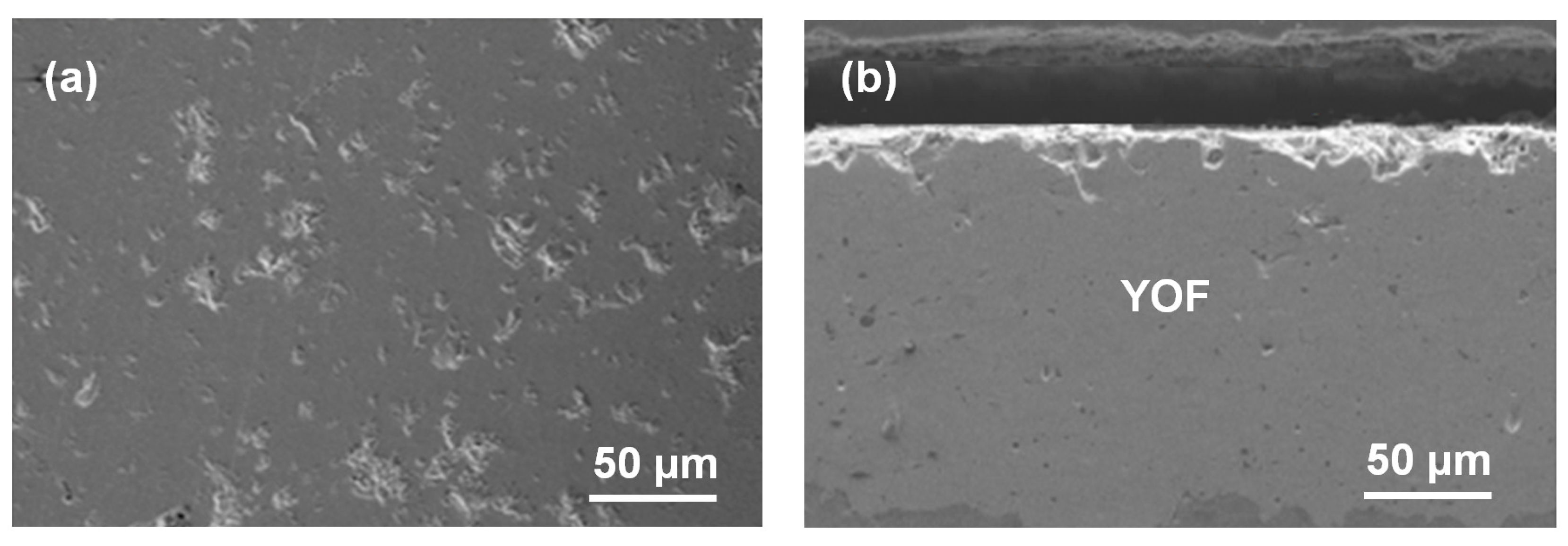
Figure 2.
XRD patterns of (a) YOF and (b) yttrium fluoride (YF3) coating deposited on an Al substrate.
Figure 2.
XRD patterns of (a) YOF and (b) yttrium fluoride (YF3) coating deposited on an Al substrate.

Figure 3.
Energy dispersive X-ray diffraction (EDX) results of (a) YOF and (b) YF3 coated under a plasma spray power of 15 kW.
Figure 3.
Energy dispersive X-ray diffraction (EDX) results of (a) YOF and (b) YF3 coated under a plasma spray power of 15 kW.

Figure 4.
Cross-sectional transmission electron microcopy (TEM) images of (a) YOF and (b) YF3 coated under a plasma spray power of 15 kW.
Figure 4.
Cross-sectional transmission electron microcopy (TEM) images of (a) YOF and (b) YF3 coated under a plasma spray power of 15 kW.
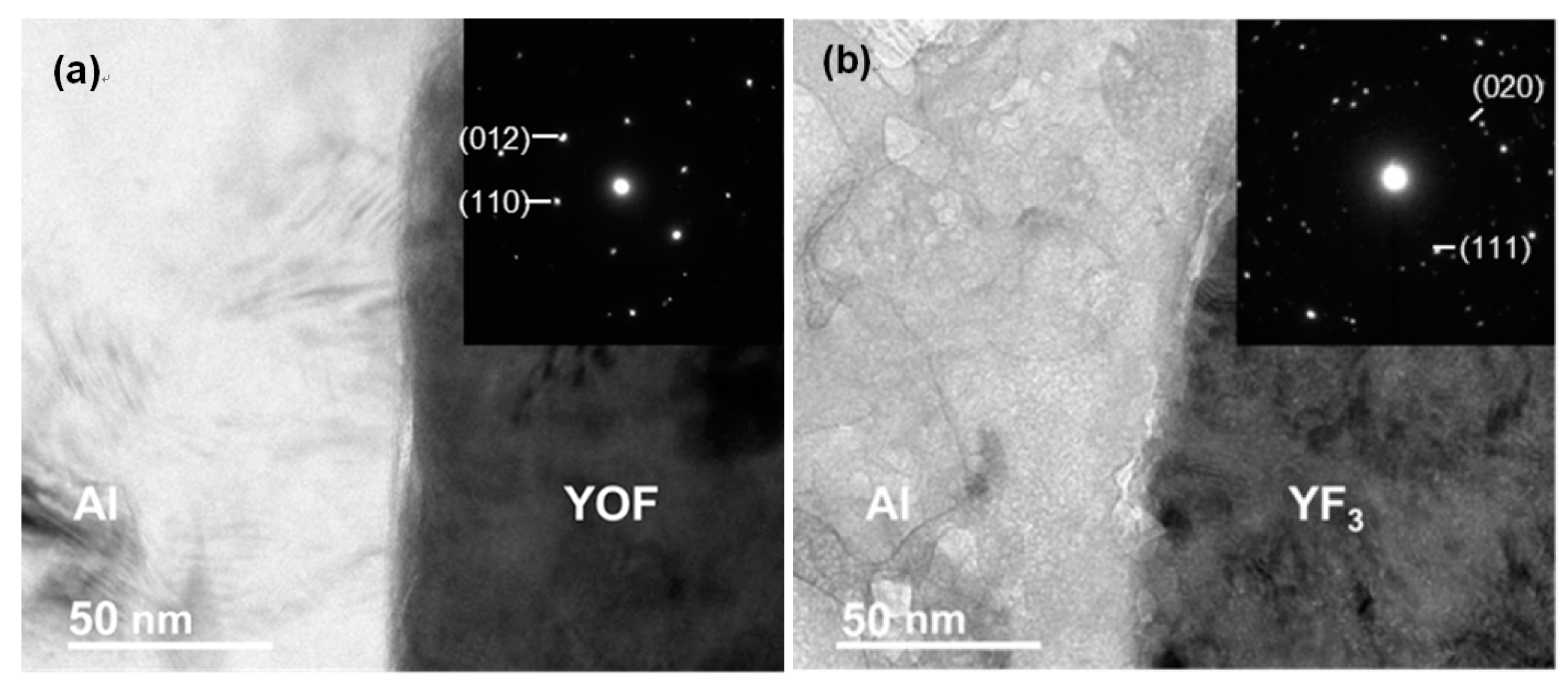
Figure 5.
Porosities of the YOF and YF3 coatings obtained under different plasma-spray powers.
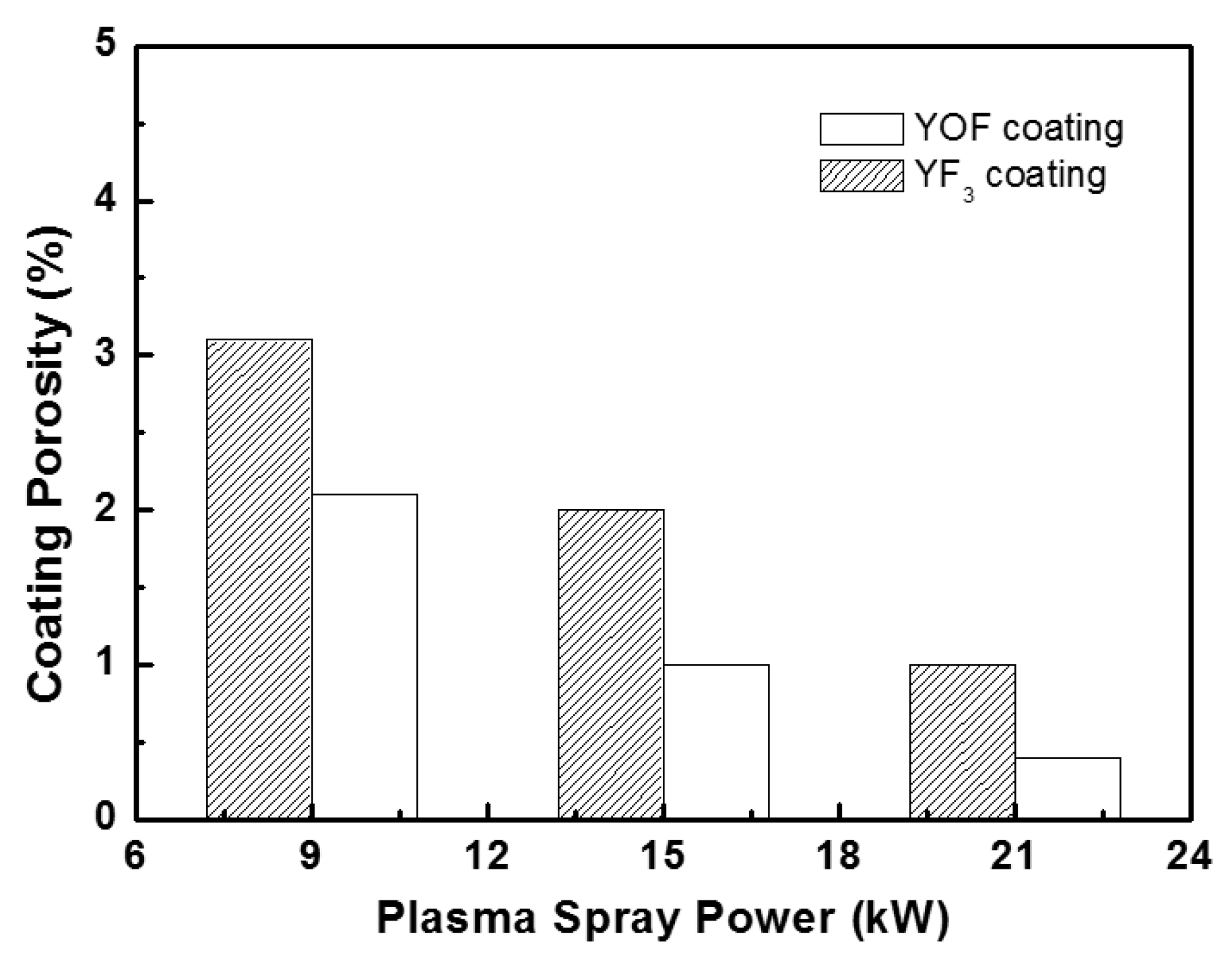
Figure 6.
Variations of chemical compositions measured by X-ray photoelectron spectroscopy (XPS) with the sputtering times of (a) YOF and (b) YF3 coatings.
Figure 6.
Variations of chemical compositions measured by X-ray photoelectron spectroscopy (XPS) with the sputtering times of (a) YOF and (b) YF3 coatings.

Table 1.
Spraying parameters of the yttrium oxyfluoride (YOF) and yttrium fluoride (YF3) coatings.
| Sparaying Parameters | YOF | YF3 |
|---|---|---|
| Gun power (kW) | 15 | 15 |
| Gun moving rate (cm) | 10 | 10 |
| Argon flow rate (L/min) | 45 | 45 |
| Hydrogen flow rate (L/min) | 6 | 6 |
| Target to substrate distance (cm) | 10 | 10 |
Table 2.
Compositions of YOF and YF3 obtained by energy dispersive X-ray diffraction (EDX).
| Atoms | YOF | YF3 | ||
|---|---|---|---|---|
| (at.%) | (wt.%) | (at.%) | (wt.%) | |
| Fluoride atom | 26.02 | 11.67 | 64.62 | 01.68 |
| Yttrium atom | 36.01 | 75.27 | 27.01 | 32.78 |
| Oxygen atom | 25.27 | 09.51 | 03.93 | 64.11 |
Table 3.
Mechanical and electrical properties of YOF and YF3.
| Mechanical Properties | YOF | YF3 |
|---|---|---|
| Vickers hardness (HV) | 290 ± 30 | 260 ± 25 |
| Adhesion strength (MPa) | 7.35 | 8.56 |
| Dielectric strength (kV/mm) | 24.67 | 22.65 |
| Breakdown voltage (kV) | 5.57 | 4.87 |
| Volume resistivity (Ω⋅cm) | 1016 | 1014 |
© 2018 by the authors. Licensee MDPI, Basel, Switzerland. This article is an open access article distributed under the terms and conditions of the Creative Commons Attribution (CC BY) license (http://creativecommons.org/licenses/by/4.0/).
Share and Cite
MDPI and ACS Style
Lin, T.-K.; Wuu, D.-S.; Huang, S.-Y.; Wang, W.-K. Preparation and Characterization of Sprayed-Yttrium Oxyfluoride Corrosion Protective Coating for Plasma Process Chambers. Coatings 2018, 8, 373. https://doi.org/10.3390/coatings8100373
AMA Style
Lin T-K, Wuu D-S, Huang S-Y, Wang W-K. Preparation and Characterization of Sprayed-Yttrium Oxyfluoride Corrosion Protective Coating for Plasma Process Chambers. Coatings. 2018; 8(10):373. https://doi.org/10.3390/coatings8100373
Chicago/Turabian StyleLin, Tzu-Ken, Dong-Sing Wuu, Shih-Yung Huang, and Wei-Kai Wang. 2018. "Preparation and Characterization of Sprayed-Yttrium Oxyfluoride Corrosion Protective Coating for Plasma Process Chambers" Coatings 8, no. 10: 373. https://doi.org/10.3390/coatings8100373
Note that from the first issue of 2016, this journal uses article numbers instead of page numbers. See further details here.