Article

Investigation into Performance of Multilayer Composite Nano-Structured Cr-CrN-(Cr0.35Ti0.40Al0.25)N Coating for Metal Cutting Tools

1
Department of High-Efficiency Processing Technologies, Moscow State Technological University STANKIN, 127055 Moscow, Russia
2
Department of Mechanical Engineering, Moscow State Technological University STANKIN, 127055 Moscow, Russia
3
Department of Solid State Physics and Nanosystems, National Research Nuclear University MEPhI, 115409 Moscow, Russia
4
Materials Science and Metallurgy Shared Use Research and Development Center, National University of Science and Technology MISIS, 119049 Moscow, Russia
5
Material Properties Research Laboratory, Moscow State Technological University STANKIN, 127055 Moscow, Russia
*
Author to whom correspondence should be addressed.
Coatings 2018, 8(12), 447; https://doi.org/10.3390/coatings8120447
Submission received: 5 November 2018 / Revised: 26 November 2018 / Accepted: 3 December 2018 / Published: 6 December 2018
(This article belongs to the Special Issue Coatings for Cutting Tools)

Abstract

:
This paper deals with the Cr-CrN-(Cr0.35Ti0.40Al0.25)N coating. It has a three-layered architecture with a nano-structured wear-resistant layer. The studies involved the investigation into the microstructure (with the use of SEM and TEM), elemental and phase composition (XRD and SAED patterns), wear process pattern in scratch testing, crystal structure, as well as the microhardness of the coating. Cutting tests of tools with the above coating were carried out in dry turning of steel 1045 at cutting speeds of vc = 200, 250, and 300 m·min−1. The comparison included uncoated tools and tools with the commercial TiN and (Ti,Al)N coatings with the same thickness. The tool with the Cr-CrN-(Cr0.35Ti0.40Al0.25)N coating showed the longest tool life at all the cutting speeds under consideration. Meanwhile, a tool with the coating under study can be recommended for use in turning constructional steel at the cutting speed of vc = 250 m·min−1. At this cutting speed, a tool shows the combination of a rather long tool life and balanced wear process, without any threat of catastrophic wear.

1. Introduction

The (Ti,Cr,Al)N coatings with different ratios of the composition elements were investigated in a large number of studies [1,2,3,4,5,6,7,8,9,10,11,12,13], which showed the high efficiency of the coatings under study due to their good resistance to oxidation and wear at high temperatures. This combination of properties opens up wide opportunities for their use as a wear-resistant coating for metal cutting tools, including those operated at high cutting speeds at high temperatures.
An increase in temperature initiates macro- and micro-fractures on contact pads of the tool. With an increase in the cutting speed, there is a tendency for the isotherms of maximum temperatures to move towards the cutting edge and to the flank face of the tool [1,2,3,4]. This is determined by a change in the contact characteristics: A decrease in the total contact length on the rake face and a slight increase in the length of total contact on the flank face, an increase in the shear angle and a decrease in secondary deformations. The pattern of the change in an isotherm in the cutting part of the tool also explains a decrease in intensity of the crater formation for coated tools. Thus, in terms of estimating the thermal state of the cutting tool, a greater effect from the coating can be achieved at high cutting speeds. When assessing the effect of the coating on the thermal state of the cutting zone and the cutting tool, it is necessary to take into account the very complex changes introduced by the coating to the contact processes, the chip formation mechanism and the formation of contact areas, the buildup process, and the change in plastic shear resistance. Thus, a favourable redistribution of heat flows in cutting with the coated tool and is an extremely important control function of the coating in terms of improving cutting performance and increasing tool efficiency [1,4].
In particular, Yamamoto et al. [5] found that the coating under study showed good oxidation resistance till 1000 °C, i.e., 200 °C higher than the (Ti,Al)N coating. It was also found [6] that at a temperature of about 900 °C, a cubic structure in the coating under study transformed into a hexagonal one, and that led to a decrease in the coating hardness by about 4 GPa. It was found [7] that the (Ti,Cr,Al)N nanolayer had a cubic structure, while the (Al,Si)N nanolayer had a hexagonal structure. The hardness of the coating and its thermostability increased when the value thickness of the binary nanolayer λ decreased. The cutting tests conducted in end milling of H13 steel (HRC 50) showed [8] a significant increase (by two times) in tool life compared to the traditional (Ti,Al)N coating. During the consideration of a tool with the specified coating for machining workpieces of H13 (HRC 50–52) tool steel, as well as TiAl6V4 alloy and Ni-based superalloy, it was found [9] that the (Ti,Cr,Al)N coating showed the best result in the machining of hardened steel, with high temperatures in the cutting zone. Meanwhile, the (Ti,Al)N coating showed the best result in machining of TiAl6V4 alloy and Ni-based superalloy. The authors explain [9] the difference by cutting conditions: The value of resistance to oxidation and hardness at high temperatures in the machining of hardened steel and the value of plasticity and resistance to brittle fracture in machining of the above alloys. The study [10] revealed the presence of the TiCrN2 phase in the composition of the specified coating, as well as the solid solution of Cr and Al in titanium nitride of (Ti,Cr,Al)N, with the lattice parameter of a = 4.244–4.223 Å (depending on the Cr content). It was found [11,12] that at room temperature, the (Ti,Al,Cr)N and (Ti,Al)N coatings showed similar tribological properties, but at a temperature of 650 °C, the Cr-containing coatings showed the best properties due to the formation of chromium oxide tribofilm, superior to similar films based on Al and Ti oxides. Meanwhile, the tribological properties increased with an increase of Cr content in the coating. The cutting tests showed [11,12] that at low cutting speeds, a coating without Cr content demonstrated the best result due to its higher hardness and, respectively, wear resistance. However, with an increase in cutting speed, the tools with Cr-containing coatings showed a noticeable decrease in cutting force and a longer tool life due to an active formation of oxide tribofilms. The study [13] revealed the formation of the oxides of Cr2O3, α-Al2O3, SiO2 and rutile-TiO2 at temperatures of 600–1000 °C. The oxidation tests carried out at temperatures of 500–900 °C showed [14] the best oxidation resistance of the (Cr,Ti,Al)N coating in combination with good structural stability at high temperatures. It was found that the high oxidation resistance was provided due to the formation on surface of the Cr2O3 and Al2O3 films, effectively preventing further diffusion of oxygen into the coating. At a temperature of 900 °C, the coating under study retained its crystal structure, surface morphology, hardness, and wear resistance. It was found [15] that while at room temperature, the maximum hardness was observed for the coatings with high Cr content (38–39 at.%), then at a temperature of 900 °C, the maximum hardness was demonstrated by the (Ti,Al)N coating, and at a temperature of 1100 °C—by the coatings with low Cr content (7 and 28 at.%). Meanwhile, the coatings with high Ti content showed the lowest resistance to oxidation at high temperatures due to the lowest protective properties of the TiO2 oxide film compared to Cr2O3 and Al2O3. It was found [16] that the coating structure (fcc-(Cr,Al)N and h-(Al,Si)N phases) did not fail until reaching a temperature of 900 °C, and at higher temperatures, the fcc-CrN phase decomposed with the formation of the h-Cr2N, cubic Cr, and Al80Cr20 phases. The coating retained its high resistance to oxidation until the temperature of 900 °C. Introduction of Cr in the coating content inhibited the transformation of an-TiO2 into r-TiO2, and also inhibited the growth of a porous sublayer, rich in titanium oxides, and thus increased the oxidation resistance of the coating [14]. The best results at room temperature and at a temperature of 400 °C were demonstrated by the (Cr0.40Ti0.22Al0.38)N coating [17,18]. Lin et al. [19] found that the (Cr0.61Ti0.10Al0.29)N coating showed the maximum hardness (40 GPa) and wear resistance, as well as the minimum friction coefficient both at room temperature and at temperatures of 600–800 °C. The coating also showed the resistance to oxidation at temperatures of up to 1000 °C. With an increase in the Ti content in the coating, the specified properties decreased. Lu et al. [20] considered the Cr-CrN-(Cr,Ti,Al)N coating. The outer wear-resistant layer with a thickness of about 2 µm had a columnar structure. The cutting tests conducted in end milling of hardened steel P20 (HRC 45) showed a significant increase in tool life compared to an uncoated tool.
Thus, summarizing the research experience available, it is possible to draw the following conclusions:
  • The (Cr,Ti,Al)N coating can be effectively used to improve tool life of cutting tools under conditions of high temperatures in the cutting zone and active abrasive wear.
  • An increase in Ti (over 25–28 at.%) in the coating composition leads to an increase in its hardness and wear resistance, especially at high temperatures, but worsens its oxidation resistance.
  • Accordingly, with an increase in the Cr content, the friction coefficient decreases and the resistance to oxidation at high temperatures increases.
  • The use of nanolayer coatings makes it possible to further improve the performance properties of cutting tools.

2. Materials and Methods

The multilayer Cr-CrN-(Cr0.35Ti0.40Al0.25)N coating with a nano-structured outer wear-resistant layer was taken as an object of this study. It was anticipated that such a coating would provide a balanced combination of wear resistance, thermostability, resistance to high temperature oxidation, and brittle fracture. The three-layer architecture of the coating was used (adhesive layer–transition layer–wear-resistant layer), and considered in previous works [21,22,23,24,25].
For coating deposition, the filtered cathodic vacuum-arc deposition (FCVAD) VIT-2 unit (MSTU STANKIN-IKTI RAN, Moscow, Russia) [26,27,28,29,30,31] was used. These coatings were deposited on carbide inserts.
The deposition process parameters (n—rotation speed of a turntable, IAl—Al cathode arc current, ITi—Ti cathode arc current, ICr—Cr cathode arc current, Ub—value of the displacement potential on the substrate and PN—the pressure of the reaction gas (nitrogen)) are presented in Table 1. During the deposition process, three-cathode systems with Cr (99.97%), Ti (99.98%) and Al (98.2% + 1% Si) cathodes were used.
The cutting tests were carried out in dry cutting of a workpiece made of steel 1045 to study the effect of cutting speed on tool life of a tool with the coating under study, at three different cutting speeds: vc = 200, 250, and 300 m·min−1 (f = 0.2 mm·rev−1; ap = 1.0 mm). Conditions of the cutting tests: Turning material: Steel AISI 1045 (HB 180), workpiece sizes: diameter 250 mm, length 400 mm; cutting tool: Carbide inserts SNUN ISO 1832:2017 [32]. (WC + 12% TiC + 6% Co, Kirovgrad Carbide Plant, Russia); tool geometry: The rake angle Υ = −7°; the clearance angle α = 7°; the tool cutting edge inclination λ = 0; the nose radius R = 0.8 mm; The flank wear VBmax = 0.4 mm was assumed as the failure criterion. Based on the data available [33,34,35], it could be predicted that at lower cutting speeds, the abrasive wear was essential and that predetermined the need to use a coating with the maximum hardness and wear resistance. As cutting speed increases, a temperature in the cutting zone rises and adhesive, oxidative, and diffusion components of the wear mechanism come to the fore. Accordingly, the coating used in such conditions should have good thermo- and oxidation resistance in combination with the resistance to brittle fracture, reduced tendency to adhesion to the material being machined, as well as good barrier properties against diffusion.
An uncoated tool and tools with the TiN and (Ti,Al)N coatings with similar thickness of about 3 µm were used as an object of comparison.
For microstructural studies of samples, a SEM FEI Quanta 600 FEG (Materials & Structural Analysis Division, Hillsboro, OR, USA) was used. The microhardness (HV) of coatings was measured by using the method of Oliver and Pharr [36], at a fixed load of 20 mN. The adhesion characteristics were studied on a Nanovea scratch tester (Micro Scratch, Nanovea, Irvine, CA, USA). The tests were carried out with the load linearly increasing from 0.05 to 40 N [37].
To determine the phase composition of the coating, X-ray structural phase analysis was used. Diffraction patterns were taken on a PANalytical Empyrean Series 2 X-ray diffractometer (Malvern Panalytical Ltd., Malvern, UK) using monochromatic CuKα radiation, in an asymmetric geometry (sliding beam) using a parallel beam. The analysis of the phase composition was carried out using the software PANalytical High Score Plus and the database ICCD PDF-2.
The structure of the crystals was studied under a JEM 2100 (JEOL, Tokyo, Japan) microscope at an acceleration voltage of 200 keV. Samples for TEM study were prepared by Strata FIB 205 System (FEI Company, Hillsboro, OR, USA). Element analyses were carried out by EDX INCA Energy (Oxford Instruments, Oxfordshire, UK).

3. Results

Following the study of the coating microstructure (Figure 1 and Figure 2), it was possible to make the following conclusions:
  • The total coating thickness was about 3 µm, the thickness of the transition CrN layer was about 300 nm (Figure 1), the thickness of the adhesive Cr layer was about 20 nm (Figure 2, Area I).
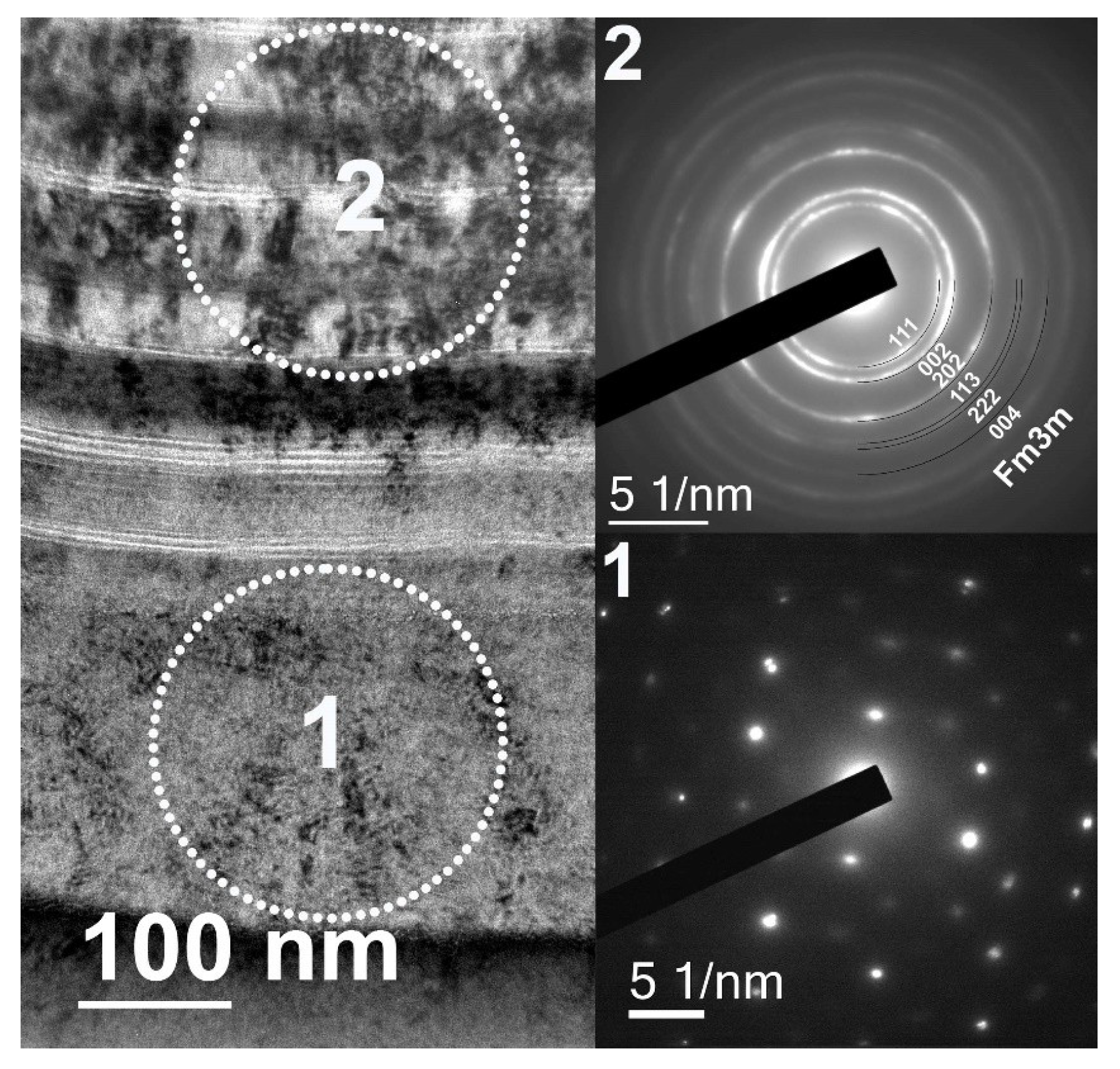
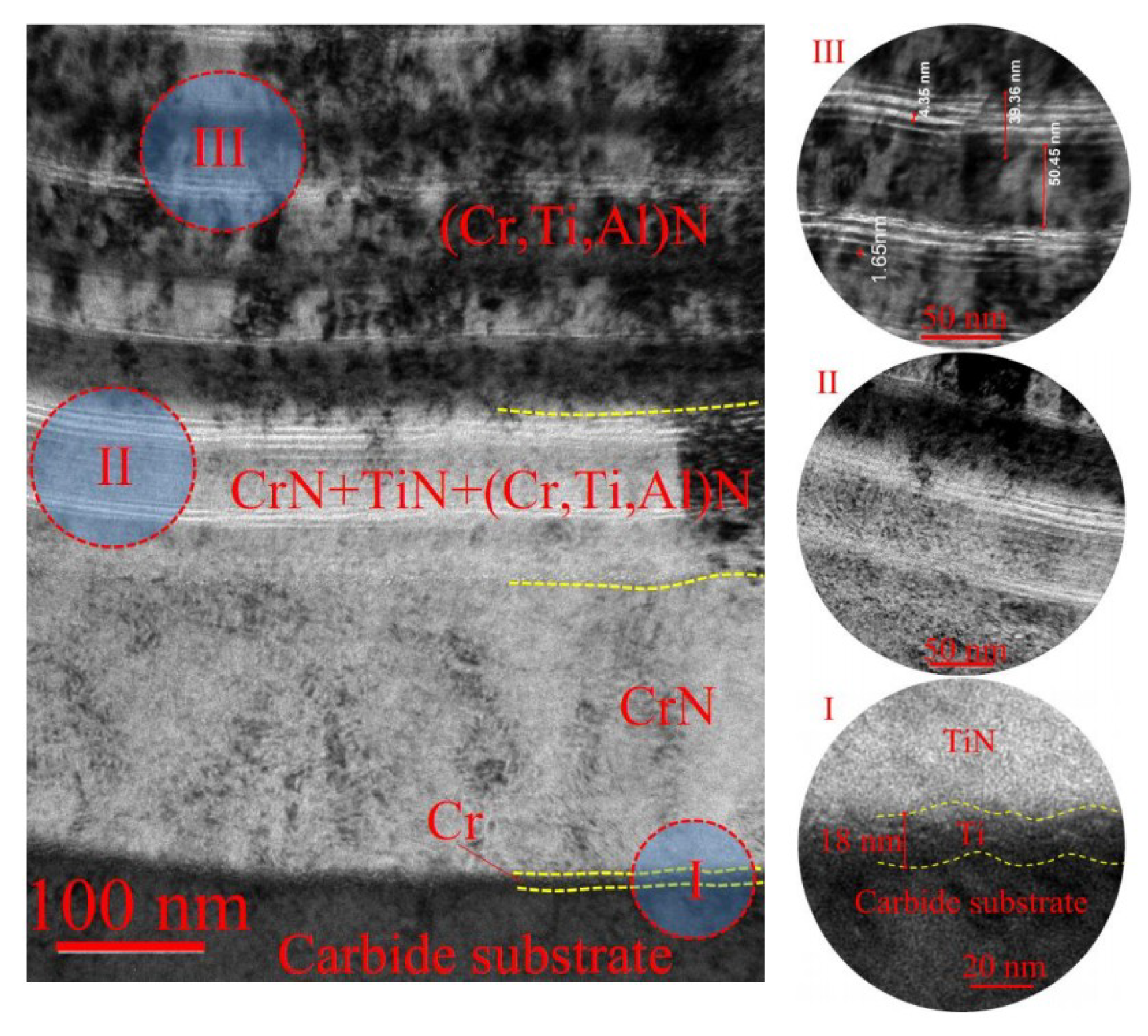
  • The wear-resistant layer included 24 binary nanolayers. The thickness of subnanolayers in the wear-resistant layer was 1.5–5.0 nm (Figure 2, Area III), with the thickness of the binary nanolayer of λ = 102 nm.
  • There was an area with low Al content between the transition and wear-resistant layers. The formation of the above area was connected with the provision of a gradient transition from the coating containing no Al to the coating with the Al content of about 25 at.% (Figure 1c and Figure 2, Area II).
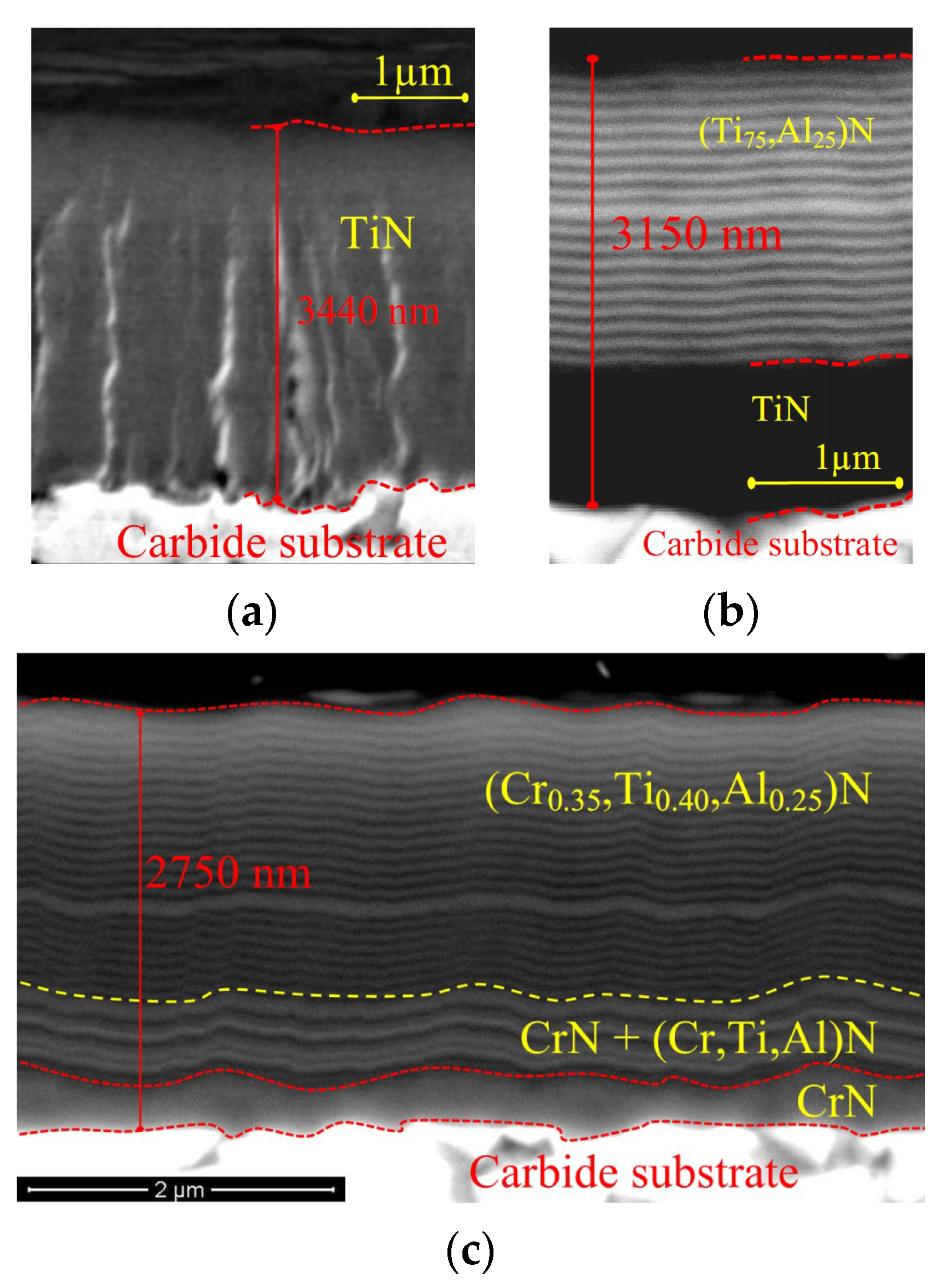
  • The following commercial coatings were selected as objects of comparison in the study of cutting properties: TiN monolayer coating (thickness was about 3 μm, Figure 1a) and multilayer nanostructured coating TiN-(Ti75Al25)N with a total thickness of about 3 μm (Figure 1b). These coatings are widely used in the manufacture of metal-cutting tools.
Let us consider the specifics of the elemental composition of the deposited coating (Figure 3). Let us consider the upper layer of the (WC + TiC + Co) substrate at a distance of about 100 nm from the surface (Figure 3, Area 1). In this area, there were such elements in the composition of the carbide, as W and Ti. The presence of a small amount of Cr could be explained by the diffusion of this element from the inner layers of the coating. While considering the composition of the transition layer of the coating (Figure 3, Area 2), it was possible to note the presence of Cr and the small presence of Ti (it could be explained by the diffusion both from the carbide substrate and from the wear-resistant layer). In the layers of the wear-resistant layer, immediately adjacent to the transition layer (Figure 3, Area 3), there was a noticeable presence of Cr and Ti with a small Al content. Upon the further deposition of the coating, a gradient increase in the Al content occurred, and that could be noted in the elemental analysis data (Figure 3, Areas 4 and 5; with Area 5 located at a distance of about 1 µm from the boundary with the transition layer).
The coating was textured, the intensities of the reflections of the diffraction pattern of the coating were different from the theoretical spectrum. It was also possible that there was the presence of micro- and macrostress, which leads to the broadening and displacement of reflexes. Broadening of the reflections on the diffraction pattern can also be obtained on the nanoscale microstructure of the coating.
The conducted phase analysis of the wear-resistant layer of the coating (Figure 4) showed the presence in the coating of such phases as CrTiN2, AlTiN2, (Cr,Ti,Al)N. The sample included two phases of complex nitrides AlTiN2 and CrTiN2, solid solution (Cr,Ti,Al)N and reflexes of the WC substrate.
Solid solution (Cr,Ti,Al)N had a cubic NaCl-type structure, the space group Fm-3m (Pearson symbol cF8), and the crystal lattice parameter of 4.2 Å.
The complex nitride of CrTiN2 had a cubic structure of NaCl-type, space group Fm-3m (Pearson symbol cF8), and the crystal lattice parameter was 4.184 Å. The complex nitride of AlTiN2 had a cubic structure of NaCl-type, space group Fm-3m (Pearson symbol cF8), and the crystal lattice parameter was 4.194 Å.
The lines of the theoretical spectra of complex nitrides were located very close to each other. In view of the broadening and displacement of the reflexes and the textured coating, it was impossible to resolve the reflexes of these nitrides. It was also possible that the mixture of these two nitrides was present. It was formed on the basis of TiCrN2 nitride and it is a solid aluminum solution based on TiCrN2 nitride, since Al is highly soluble in Ti.
The WC substrate phase had a hexagonal structure, space group P-6m2, and the crystal lattice parameters were 2.907 and 2.837 Å.
Figure 5 presents the TEM analysis of the crystal structure of the coating under study. SAD aperture is shown as a dotted circle in Figure 5. The layer of CrN consisted of large grains, as evidenced by the selected area diffraction patterns (SAED) 1 in Figure 5. The overlying layer (Cr,Ti,Al)N coatings had a polycrystalline structure, SAED pattern 2 Figure 5. There was also the presence of texture maxima. SAED pattern 2 was defined as the space group Fm-3m.
The microhardness of the coating measured at the load of 20 mN was 32 ± 1.4 GPa. The measurement was carried out at 7 points, with the determination of the average value.
Figure 6 shows a panorama of a scratch on the Cr-CrN-(Ti,Cr,Al)N coating. The first signs of the coating failure appeared at the load of Lc1 = 19 N (zone I on Figure 6a). There were signs of brittle fracture, such as transverse cracks (A in Figure 6b) and areas of coating delamination on the scratch bottom (B1, B2 in Figure 6b). There were areas of plastic deformation of the coating (C1, C2, C3 in Figure 6b), as well as cracks and coating delamination on the edges of the scratch (D in Figure 6b). During the tests at the maximum load (40 N), no complete coating failure occurred. At the end of the scratch (Zone II in Figure 6a), there were also signs of both brittle and ductile fracture: Transverse cracks (A in Figure 6c), areas of coating delamination of the scratch bottom (B1, B2, B3 in Figure 6c), areas of plastic deformation of the coating (C in Figure 6c), and cracks and coating delamination on the edge of the scratch (D1, D2 in Figure 6c). There was slight chipping of the coating (E in Figure 6c); however, in that area, the coating did not fail to the substrate.
The results of the cutting tests in dry turning of steel 1045 are presented in Figure 7. If at the cutting speed of vc = 200 m·min−1, tools with the Cr-CrN-(Ti,Cr,Al)N and (Ti,Al)N coatings showed fairly close results, then with an increase in the cutting speed, the difference in tool life periods for the given samples increased, that may have indicated a higher thermostability and oxidation resistance of the Cr-CrN-(Ti,Cr,Al)N coating in combination with the formation on its surface of a chromium oxide-based triboactive film [38].
Let us consider the wear kinetics of a tool with the Cr-CrN-(Ti,Cr,Al)N coating under study at different cutting speeds (Figure 8, Figure 9 and Figure 10). At the cutting speed of vc = 200 m·min−1 (Figure 8), there was a noticeable formation of only a small wear center on the rake face, the wear was balanced, and flank wear is a limiting criterion.
At the cutting speed of vc = 250 m·min−1 (Figure 9), the pattern of wear varied. A pronounced crater was formed on the rake face; however, there was a sufficiently wide bridge between the cutting edge and the crater, and the wear stays balanced, with flank wear as a limiting criterion.
With a further increase in the cutting speed up to vc = 300 m·min−1 (Figure 10), the process of crater formation became more active, and a bridge between the cutting edge and the crater failed simultaneously with the achievement of the maximum wear on the flank face. Given that at the specified cutting speed, the tool with the Cr-CrN-(Ti,Cr,Al)N coating showed a sufficiently long tool life, it was clear that the further increase in the cutting speed was not advisable. A formation of an extensive crater may indicate high (close to critical) temperatures in the cutting zone and an active adhesive and oxidative wear. It should be noted that a formation of extensive craters was observed for all the tools under study, while for the uncoated tool and the tool with the TiN coating, rake wear was a limiting criterion at the specified cutting speed.
Let us consider in more detail the wear process pattern for a tool with the Cr-CrN-(Ti,Cr,Al)N coating at the cutting speeds of vc = 200 (Figure 11) and 250 m·min−1 (Figure 12). At the specified cutting speeds, the tool with the coating under study showed a fairly long tool life and a balanced wear pattern. In particular, at the cutting speed of vc = 200 m·min−1 (Figure 11), the abrasive wear predominated, there were no signs of brittle fracture of the coating, and the surface of wear was fairly smooth, without chipping and cracking (Figure 11, Area A).
At the cutting speed of vc = 250 m·min−1 (Figure 12), there were elements of brittle fracture. There was clear chipping of the carbide substrate with penetration of the material being machined into the zone of the coating failure (Figure 12, Area A). In this area, there was also the formation of through transverse cracks in the coating structure, and in some cases, it was possible to see the penetration of elements of the material being machined into a crack (Figure 12, Area D). Meanwhile, the wear process pattern on the crater boundary farthest from the cutting edge (Figure 12, Area B) stayed fairly balanced, without any noticeable signs of brittle fracture and cracking. Let us consider the wear process pattern on the flank face of the tool (Figure 12, Area C). There was a wave-like distortion of the substrate surface as a result of plastic microdeformations. Meanwhile, an adherent of the material being machined penetrated between the coating and the substrate, contributing to the coating failure. Meanwhile, there were no noticeable signs of brittle fracture of the coating in the specified zone.

4. Conclusions

This study included the investigation into the microstructure, the elemental and phase composition, and the wear process pattern in scratch testing. The microhardness of the Cr-CrN-(Cr0.35Ti0.40Al0.25)N coating was also defined. The cutting tests of the tool with the coating under study were carried out in the dry cutting of steel 1045 at the cutting speeds of vc = 200, 250, and 300 m·min−1.
After the analysis of the obtained results, it was possible to draw the following results:
  • The wear-resistant layer of the coating was nano-structured. The thickness of subnanolayers in this layer was 1.5–5.0 nm with the thickness of the binary nanolayer of λ = 102 nm.
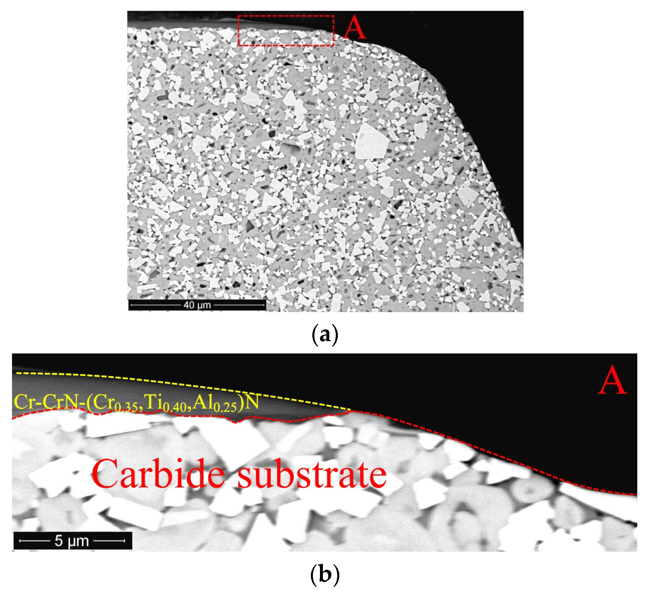
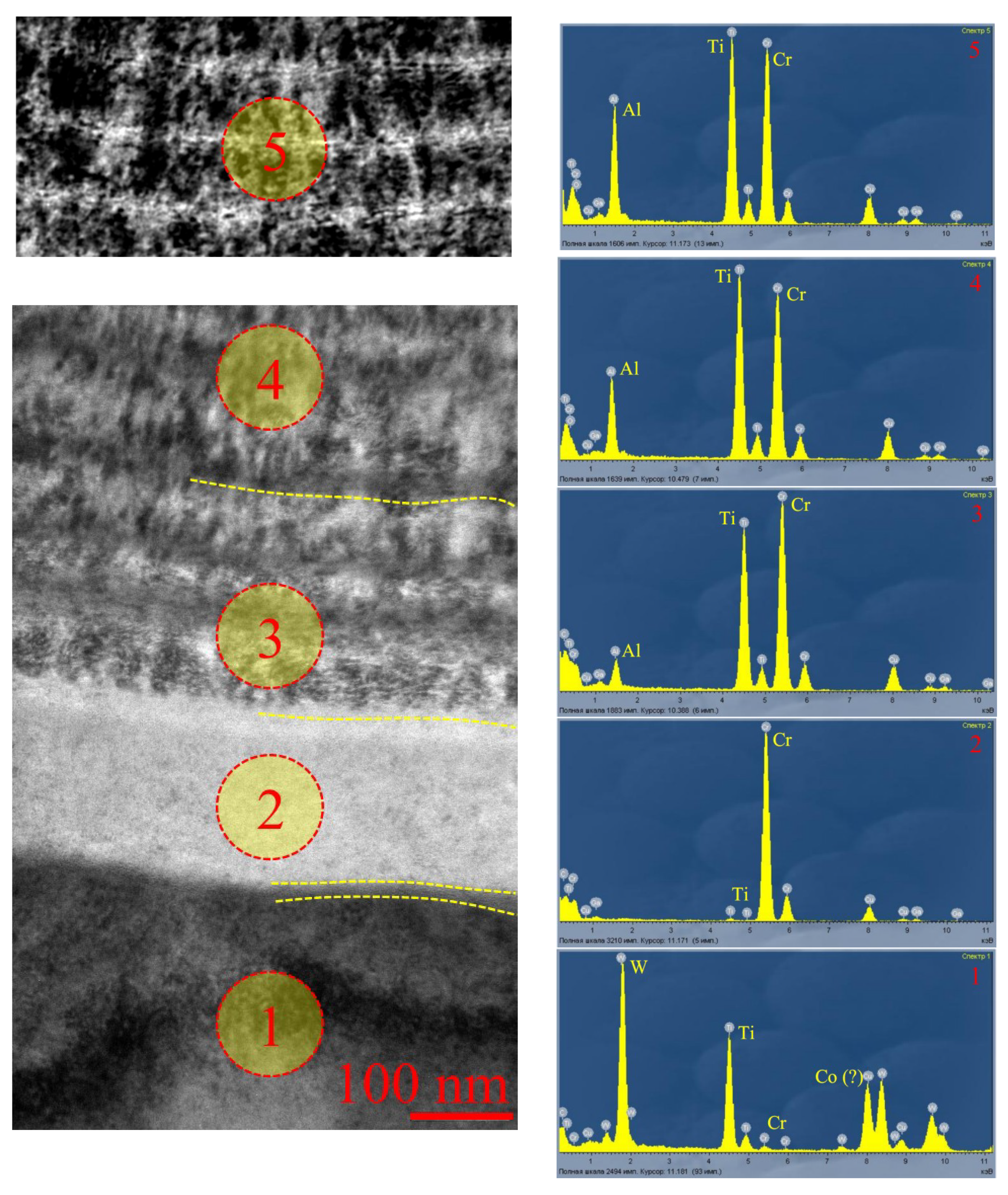
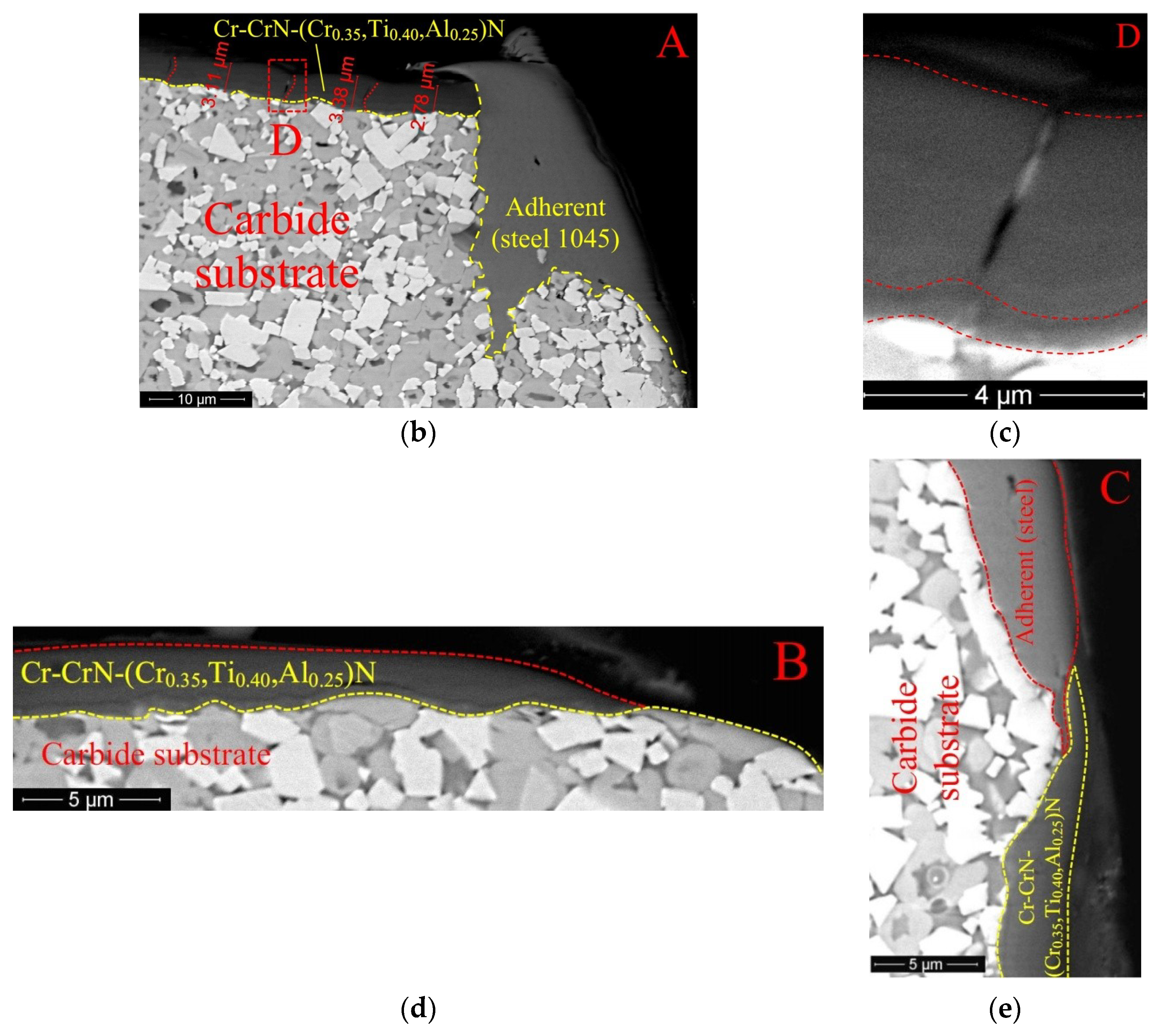
  • The surface layers of the substrate included signs of Cr diffusion from the coating composition.
  • The Al content in the composition of the wear-resistant layer showed a gradient increase over about 1 μm from the border with the transition layer.
  • The sizes of the crystals in the nano-structured wear-resistant layer were significantly smaller than in the transition layer, and that could be explained by the effect of the nanolayer thickness.
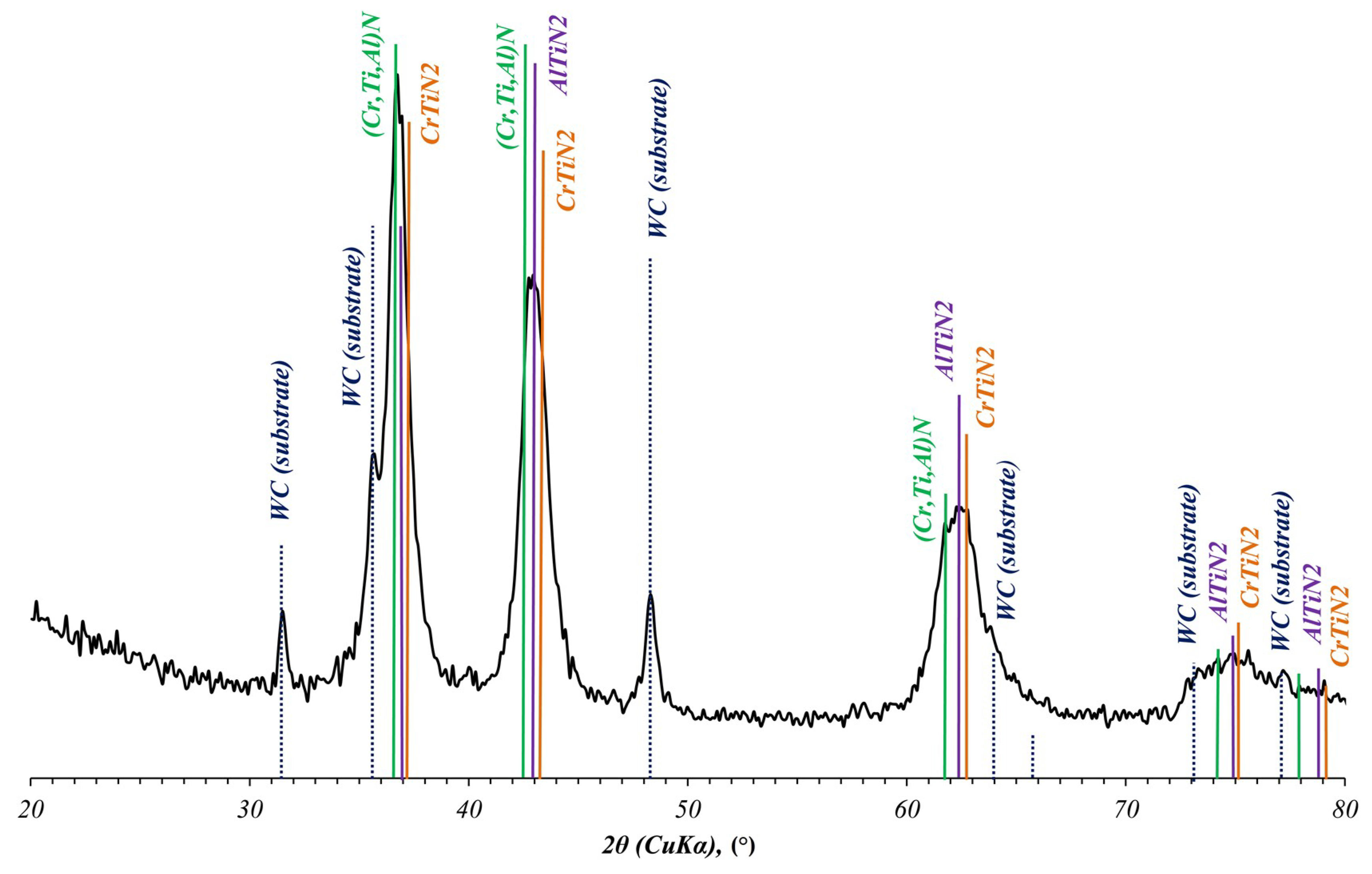
  • The conducted phase analysis of the wear-resistant coating showed the presence of such phases as TiN, CrTiN2, and Cr2N.
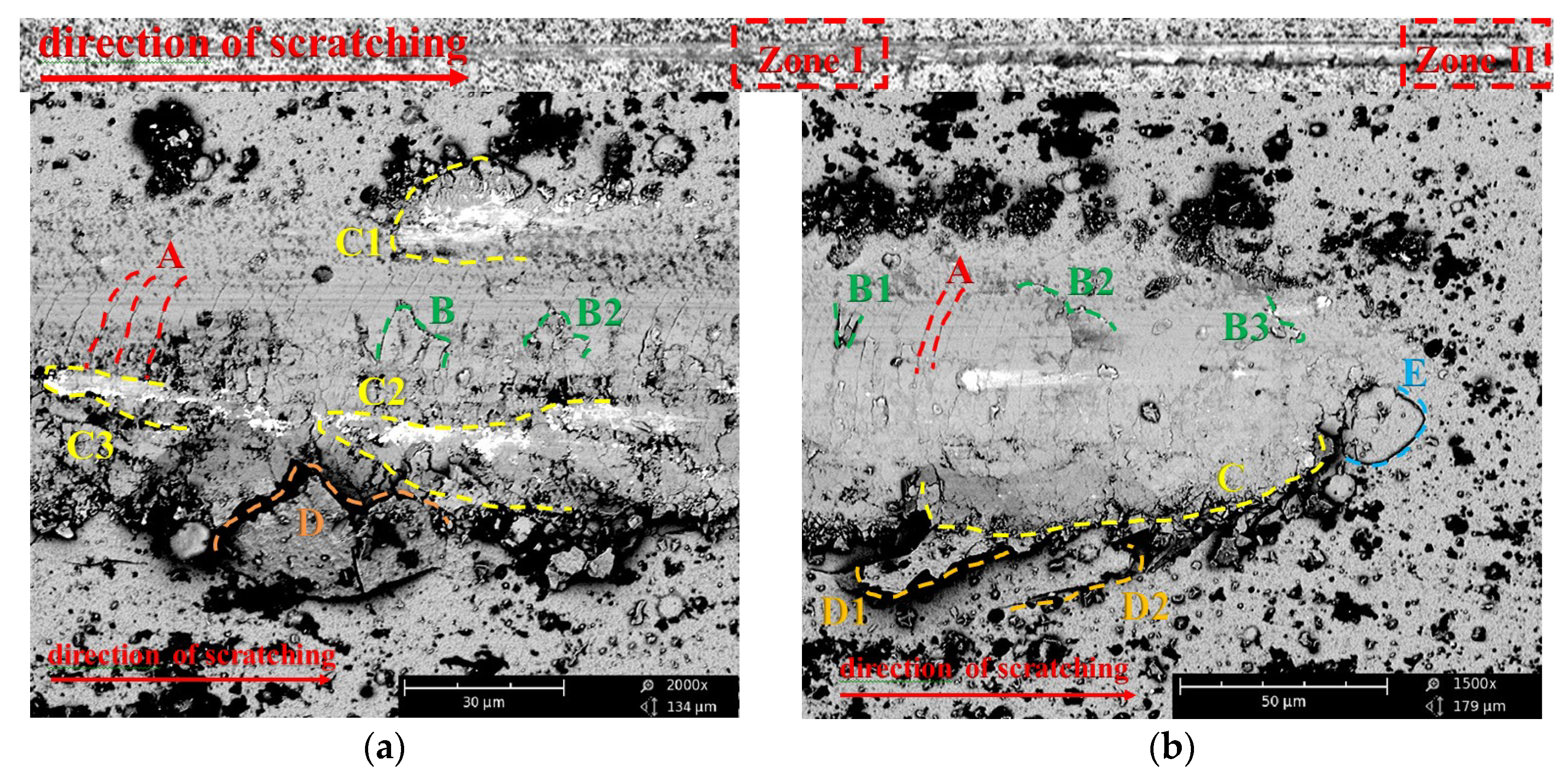
  • The coating showed good resistance of the coating to failure in scratch testing (Lc2 > 40 N), with signs of both fragile fracture and ductile failure.
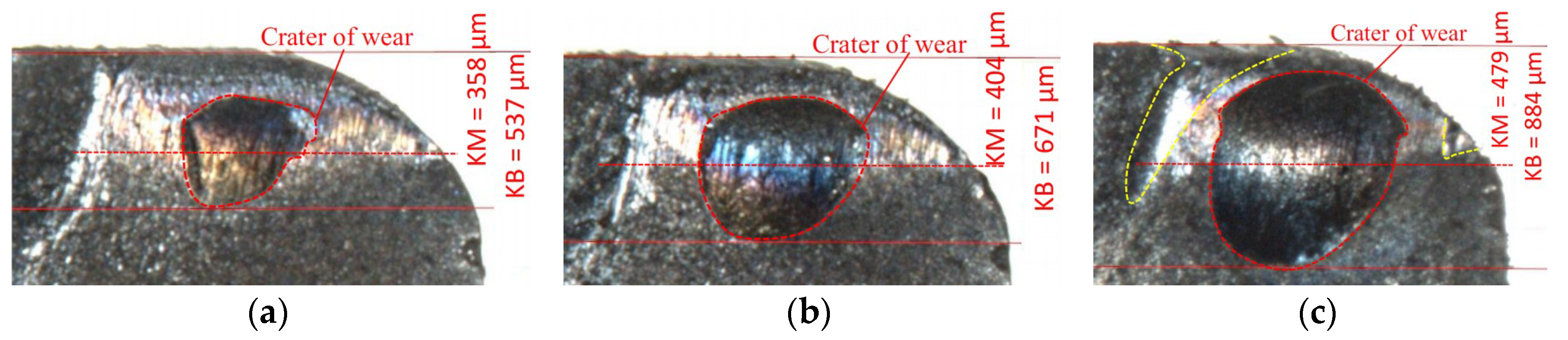
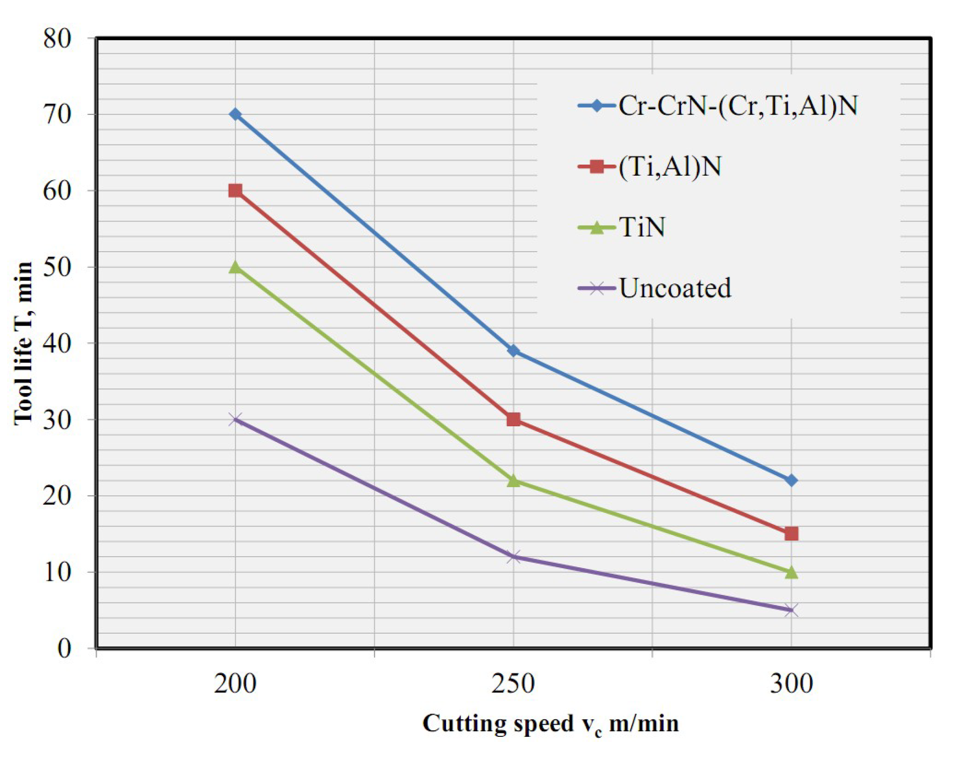
  • The tool with the coating under study showed the longest tool life in the turning of steel 1045 compared to the uncoated tool and the tools with the commercial TiN and (Ti,Al)N coatings of similar thickness.
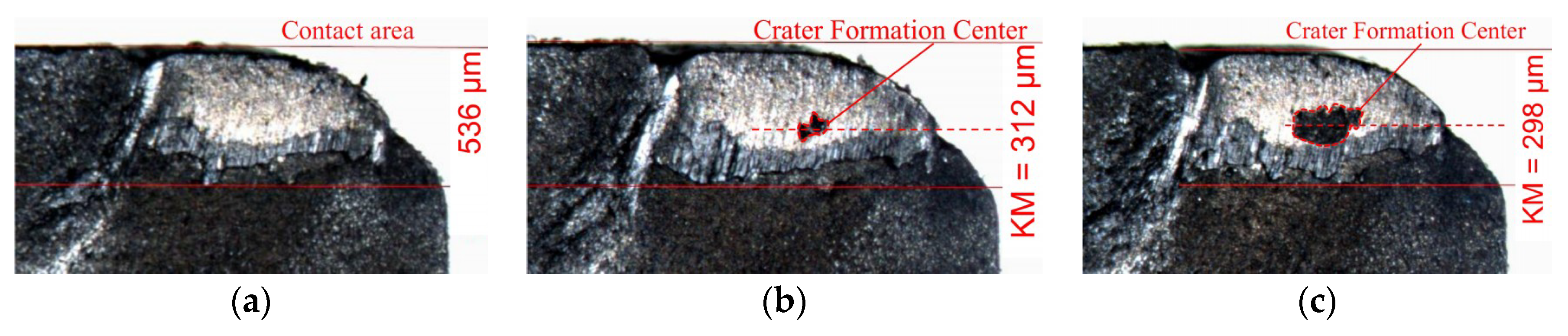
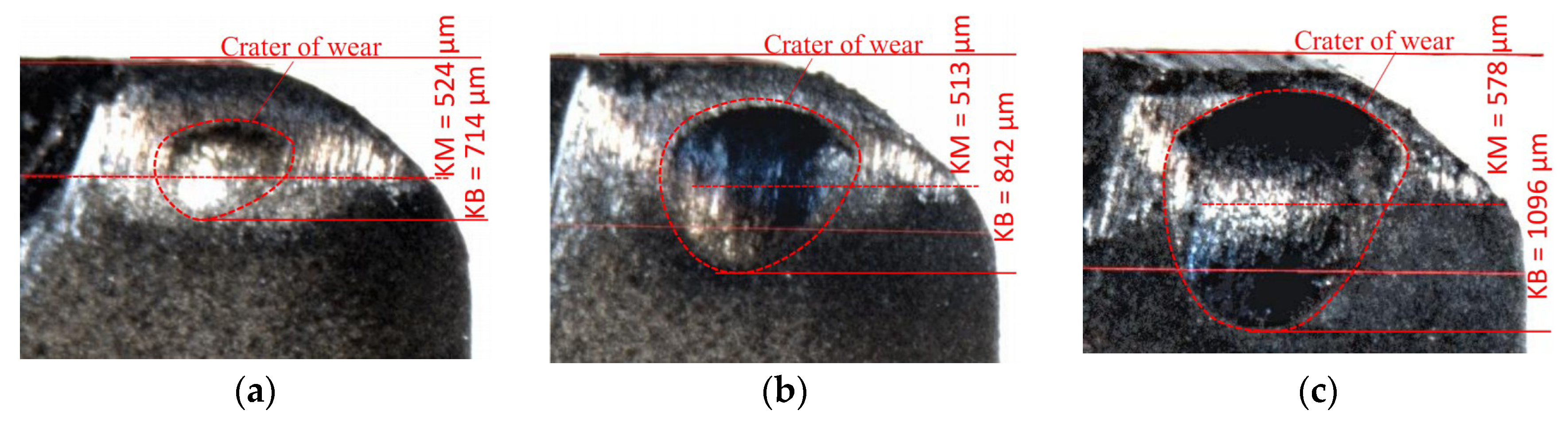
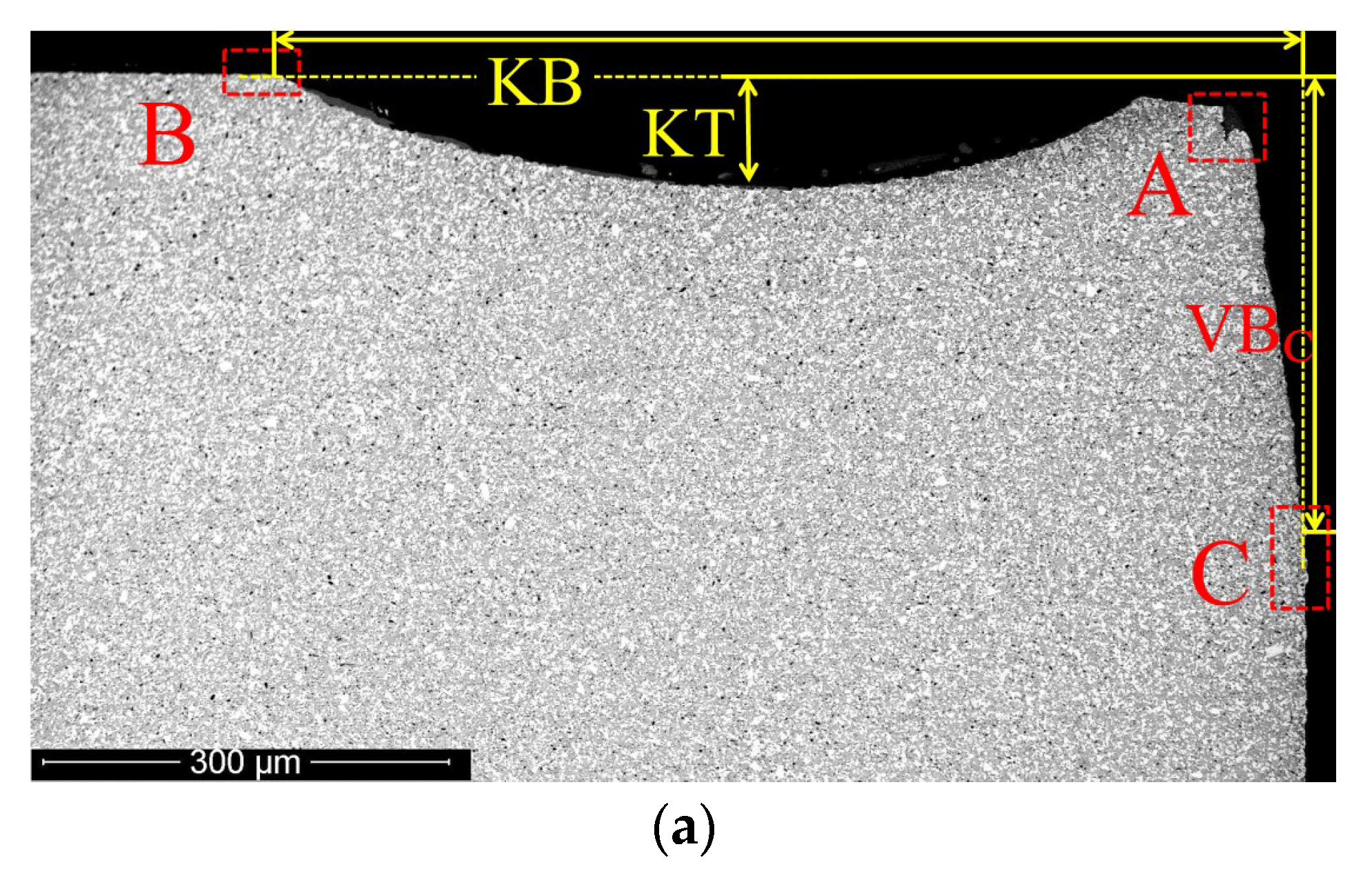
  • During turning at a cutting speed of vc = 200 m·min−1, a balanced tool wear took place, without any noticeable crater formation and signs of brittle fracture.
  • During turning at a cutting speed of vc = 250 m·min−1, the formation of a crater was observed; however, the rake wear was not a limiting criterion. There were signs of brittle fracture and formation of cracks in the coating structure.
  • During turning at a cutting speed of vc = 300 m·min−1, an active crater formation took place, and both flank and rake wear processes were limiting criteria.
Therefore, the tool with the Cr-CrN-(Cr0.35Ti0.40Al0.25)N coating showed the longest tool life at all the cutting speeds under consideration. Meanwhile, a tool with the coating under study can be recommended for use in turning steel 1045 at a cutting speed of vc = 250 m·min−1. At this cutting speed, a tool shows a combination of a rather long tool life and balanced wear process, without any threat of catastrophic wear.

Author Contributions

Conceptualization, S.G., A.V. and A.M.; Methodology, S.G. and A.V.; Validation, N.S., F.M., S.S., Y.R. and N.A.; Investigation, S.G. and A.V.; Resources, S.G. and A.V.; Data Curation, A.M.; Writing–Original Draft Preparation, A.V.; Writing–Review & Editing, A.V.; Visualization, S.S.; Supervision, S.G. and A.V.; Project Administration, S.G. and A.V.; Funding Acquisition, A.M. and S.G.

Funding

This research was funded by the Ministry of Education and Science of the Russian Federation (No. 9.7886.2017/6.7).

Conflicts of Interest

The authors declare no conflict of interest.

References

  1. Vereschaka, A.S. Working Capacity of the Cutting Tool with Wear Resistant Coatings; Mashinostroenie: Moscow, Russia, 1993. [Google Scholar]
  2. Poletica, M.F. Contact Loads on Tool Interfaces; Mashinostroenie: Moscow, Russia, 1969. [Google Scholar]
  3. Astakhov, V.P. Tribology of Metal Cutting; Elsevier: Amsterdam, the Netherlands, 2006. [Google Scholar]
  4. Astakhov, V.P. Tribology of Cutting Tools. In Tribology in Manufacturing Technology; Davim, J.P., Ed.; Springer: Berlin/Heidelberg, Germany, 2013; pp. 1–66. [Google Scholar]
  5. Yamamoto, K.; Sato, T.; Takahara, K.; Hanaguri, K. Properties of (Ti,Cr,Al)N coatings with high Al content deposited by new plasma enhanced arc-cathode. Surf. Coat. Technol. 2003, 174, 620–626. [Google Scholar] [CrossRef]
  6. Hasegawa, H.; Yamamoto, T.; Suzuki, T.; Yamamoto, K. The effects of deposition temperature and post-annealing on the crystal structure and mechanical property of TiCrAlN films with high Al contents. Surf. Coat. Technol. 2006, 200, 2864–2869. [Google Scholar] [CrossRef]
  7. Fukumoto, N.; Ezura, H.; Yamamoto, K.; Hotta, A.; Suzuki, T. Effects of bilayer thickness and post-deposition annealing on the mechanical and structural properties of (Ti,Cr,Al)N/(Al,Si)N multilayer coatings. Surf. Coat. Technol. 2009, 203, 1343–1348. [Google Scholar] [CrossRef]
  8. Fox-Rabinovich, G.S.; Yamomoto, K.; Veldhuis, S.C.; Kovalev, A.I.; Dosbaeva, G.K. Tribological adaptability of TiAlCrN PVD coatings under high performance dry machining conditions. Surf. Coat. Technol. 2005, 200, 1804–1813. [Google Scholar] [CrossRef]
  9. Fox-Rabinovich, G.S.; Kovalev, A.I.; Aguirre, M.H.; Beake, B.D.; Yamamoto, K.; Veldhuis, S.C.; Endrinof, J.L.; Wainsteinb, D.L.; Rashkovskiy, A.Y. Design and performance of AlTiN and TiAlCrN PVD coatings for machining of hard to cut materials. Surf. Coat. Technol. 2009, 204, 489–496. [Google Scholar] [CrossRef]
  10. Blinkov, I.V.; Tsareva, S.G.; Zentseva, A.V.; Volkhonskii, A.O.; Buzanov, V.I.; Stepareva, N.N. Structure and phase formation of nanostructural ion-plasma Ti-Cr-Al-N coatings on a hard-alloy cutting tool. Russ. J. Non-Ferr. Met. 2010, 51, 483–489. [Google Scholar] [CrossRef]
  11. Fernandes, F.; Danek, M.; Polcar, T.; Cavaleiro, A. Tribological and cutting performance of TiAlCrN films with different Cr contents deposited with multilayered structure. Tribol. Int. 2018, 119, 345–353. [Google Scholar] [CrossRef]
  12. Danek, M.; Fernandes, F.; Cavaleiro, A.; Polcar, T. Influence of Cr additions on the structure and oxidation resistance of multilayered TiAlCrN films. Surf. Coat. Technol. 2017, 313, 158–167. [Google Scholar] [CrossRef]
  13. Nguyen, T.D.; Kim, S.K.; Lee, D.B. High-temperature oxidation of nano-multilayered TiAlCrSiN thin films in air. Surf. Coat. Technol. 2009, 204, 697–704. [Google Scholar] [CrossRef]
  14. Zhou, Z.F.; Tam, P.L.; Shum, P.W.; Li, K.Y. High temperature oxidation of CrTiAlN hard coatings prepared by unbalanced magnetron sputtering. Thin Solid Films 2009, 517, 5243–5247. [Google Scholar] [CrossRef]
  15. Forsen, R.; Johansson, M.P.; Oden, M.; Ghafoor, N. Effects of Ti alloying of AlCrN coatings on thermal stability and oxidation resistance. Thin Solid Films 2013, 534, 394–402. [Google Scholar] [CrossRef] [Green Version]
  16. Zhang, S.; Wang, L.; Wang, Q.; Li, M. A superhard CrAlSiN superlattice coating deposited by a multi-arc ion plating: II. Thermal stability and oxidation resistance. Surf. Coat. Technol. 2013, 214, 153–159. [Google Scholar] [CrossRef]
  17. Xu, Y.X.; Chen, L.; Yang, B.; Peng, Y.B.; Du, Y.; Feng, J.C.; Pei, F. Effect of CrN addition on the structure, mechanical and thermal properties of Ti-Al-N coating. Surf. Coat. Technol. 2013, 235, 506–512. [Google Scholar] [CrossRef]
  18. Georgiadis, A.; Fuentes, G.G.; Almandoz, E.; Medrano, A.; Palacio, J.F.; Miguel, A. Characterisation of cathodic arc evaporated CrTiAlN coatings: Tribological response at room temperature and at 400 °C. Mater. Chem. Phys. 2017, 190, 194–201. [Google Scholar] [CrossRef]
  19. Lin, J.; Zhang, X.; Ou, Y.; Wei, R. The structure, oxidation resistance, mechanical and tribological properties of CrTiAlN coatings. Surf. Coat. Technol. 2015, 277, 58–66. [Google Scholar] [CrossRef]
  20. Li, L.-U.; Wang, Q.-M.; Chen, B.-Z.; Ao, Y.-C.; Yu, D.-H.; Wang, C.-Y.; Wu, S.-H.; Kim, K.-H. Microstructure and cutting performance of CrTiAlN coating for high-speed dry milling. Trans. Nonferr. Met. Soc. China 2014, 24, 1800–1806. [Google Scholar]
  21. Vereschaka, A.A.; Grigoriev, S.N.; Sitnikov, N.N.; Batako, A. Delamination and longitudinal cracking in multi-layered composite nano-structured coatings and their influence on cutting tool life. Wear 2017, 390, 209–219. [Google Scholar] [CrossRef]
  22. Vereschaka, A.A.; Grigoriev, S.N. Study of cracking mechanisms in multi-layered composite nano-structured coatings. Wear 2017, 378, 43–57. [Google Scholar] [CrossRef]
  23. Vereschaka, A.A.; Grigoriev, S.N.; Sitnikov, N.N.; Oganyan, G.V.; Batako, A. Working efficiency of cutting tools with multilayer nano-structured Ti-TiCN-(Ti,Al)CN and Ti-TiCN-(Ti,Al,Cr)CN coatings: Analysis of cutting properties, wear mechanism and diffusion processes. Surf. Coat. Technol. 2017, 332, 198–213. [Google Scholar] [CrossRef]
  24. Vereschaka, A.A.; Vereschaka, A.S.; Batako, A.D.; Hojaev, O.K.; Mokritskii, B.Y. Development and research of nanostructured multilayer composite coatings for tungsten-free carbides with extended area of technological applications. Int. J. Adv. Manuf. Technol. 2016, 87, 3449–3457. [Google Scholar] [CrossRef] [Green Version]
  25. Vereschaka, A.; Aksenenko, A.; Sitnikov, N.; Migranov, M.; Shevchenko, S.; Sotova, C.; Batako, A.; Andreev, N. Effect of adhesion and tribological properties of modified composite nano-structured multi-layer nitride coatings on WC-Co tools life. Tribol. Int. 2018, 128, 313–327. [Google Scholar] [CrossRef]
  26. Sobol’, O.V.; Andreev, A.A.; Grigoriev, S.N.; Volosova, M.A.; Gorban, V.F. Vacuum-arc multilayer nanostructured TiN/Ti coatings: structure, stress state, properties. Met. Sci. Heat Treat. 2012, 54, 28–33. [Google Scholar] [CrossRef]
  27. Metel, A.S.; Grigoriev, S.N.; Melnik, Y.A.; Prudnikov, V.V. Glow discharge with electrostatic confinement of electrons in a chamber bombarded by fast electrons. Plasma Phys. Rep. 2011, 37, 628–637. [Google Scholar] [CrossRef]
  28. Grigoriev, S.; Melnik, Y.; Metel, A. Broad fast neutral molecule beam sources for industrial-scale beam-assisted deposition. Surf. Coat. Technol. 2002, 156, 44–49. [Google Scholar] [CrossRef]
  29. Grigoriev, S.N.; Melnik, Y.A.; Metel, A.S.; Panin, V.V.; Prudnikov, V.V. A Compact Vapor Source of Conductive Target Material Sputtered by 3-keV Ions at 0.05-Pa Pressure. Instrum. Exp. Tech. 2009, 52, 731–737. [Google Scholar] [CrossRef]
  30. Metel, A.; Grigoriev, S.; Melnik, Y.; Panin, V.; Prudnikov, V. Cutting Tools Nitriding in Plasma Produced by a Fast Neutral Molecule Beam. Jpn. J. Appl. Phys. 2011, 50, 08JG04. [Google Scholar] [CrossRef]
  31. Fominskii, V.Y.; Grigor’ev, S.N.; Romanov, R.I.; Nevolin, V.N. Effect of the pulsed laser deposition conditions on the tribological properties of thin-film nanostructured coatings based on molybdenum diselenide and carbon. Tech. Phys. 2012, 57, 516–523. [Google Scholar] [CrossRef]
  32. ISO 1832:2017 Indexable Inserts for Cutting Tools—Designation; International Organization for Standardization: Geneva, Switzerland, 2017.
  33. Klocke, F.; Krieg, T. Coated tools for metal cutting—Features and applications. Ann. CIRP 1999, 48, 515–525. [Google Scholar] [CrossRef]
  34. Vereschaka, A.; Tabakov, V.; Grigoriev, S.; Aksenenko, A.; Sitnikov, N.; Oganyan, G.; Seleznev, A.; Shevchenko, S. Effect of adhesion and the wear-resistant layer thickness ratio on mechanical and performance properties of ZrN-(Zr,Al,Si)N coatings. Surf. Coat. Technol. 2019, 357, 218–234. [Google Scholar] [CrossRef]
  35. Adaskin, A.M.; Vereshchaka, A.A.; Vereshchaka, A.S. Study of wear mechanism of hard-alloy tools during machining of refractory alloys. J. Frict. Wear 2013, 34, 208–213. [Google Scholar] [CrossRef]
  36. Oliver, W.C.; Pharr, G.M. An improved technique for determining hardness and elastic modulus using load and displacement sensing indentation. J. Mater. Res. 1992, 7, 1564–1583. [Google Scholar] [CrossRef]
  37. ASTM C1624-05(2015) Standard Test Method for Adhesion Strength and Mechanical Failure Modes of Ceramic Coatings by Quantitative Single Point Scratch Testing; ASTM International: West Conshohocken, PA, USA, 2010.
  38. Vereschaka, A.; Tabakov, V.; Grigoriev, S.; Sitnikov, N.; Andreev, N.; Milovich, F. Investigation of wear and diffusion processes on rake faces of carbide inserts with Ti-TiN-(Ti,Al,Si)N composite nanostructured coating. Wear 2018, 416, 72–80. [Google Scholar] [CrossRef]
Figure 1. Microstructure of the TiN (a), TiN-(Ti75Al25)N (b) and Cr-CrN-(Cr0.35Ti0.40Al0.25)N (c) coatings (SEM).
Coatings 08 00447 g001
Figure 2. Microstructure of the Cr-CrN-(Cr0.35,Ti0.40,Al0.25)N coating (TEM).
Coatings 08 00447 g002
Figure 3. Results of the investigation of the elemental composition of the sample with the Cr-CrN-(Cr0.35,Ti0.40,Al0.25)N coating.
Coatings 08 00447 g003
Figure 4. X-ray diffraction (XRD) pattern of the Cr-CrN-(Cr,Ti,Al)N coatings on a WC-Co substrate.
Coatings 08 00447 g004
Figure 5. Crystalline structure of the sample with the Cr-CrN-(Ti,Cr,Al)N coating.
Coatings 08 00447 g005
Figure 6. Panorama of the scratch on the coating on the sample and scratch fragments at the place where the coating starts to fail (a): Zone I and at the end of the scratch (b): Zone II; A—transverse scratches in the coating; B1, B2, B3—areas of coating delamination on the scratch bottom; C, C1, C2, C3—areas of plastic deformation of the coating; D, D1, D2—areas of coating delamination on the scratch edges, E—coating chipping.
Coatings 08 00447 g006
Figure 7. Results of cutting tests in dry turning of steel 1045 (vc = 200, 250 and 300 m·min−1; f = 0.2 mm·rev−1; ap = 1.0 mm).
Coatings 08 00447 g007
Figure 8. Wear kinetics for a tool with the Cr-CrN-(Ti,Cr,Al)N coating at vc = 200 m·min−1; f = 0.2 mm·rev−1; ap = 1.0 mm; (a) 55 min; (b) 60 min; (c) 70 min of cutting.
Coatings 08 00447 g008
Figure 9. Wear kinetics for a tool with the Cr-CrN-(Ti,Cr,Al)N coating at vc = 250 m·min−1; f = 0.2 mm·rev−1; ap = 1.0 mm; (a) 14 min; (b) 27 min; (c) 39 min of cutting.
Coatings 08 00447 g009
Figure 10. Wear kinetics for a tool with the Cr-CrN-(Ti,Cr,Al)N coating at vc = 300 m·min−1; f = 0.2 mm·rev−1; ap = 1.0 mm; (a) 7 min; (b) 14 min; (c) 22 min of cutting.
Coatings 08 00447 g010
Figure 11. Wear pattern on a tool with the Cr-CrN-(Ti,Cr,Al)N coating at vc = 200 m·min−1, after 70 min of cutting. General view (a); area A (b).
Coatings 08 00447 g011
Figure 12. Wear pattern on a tool with the Cr-CrN-(Ti,Cr,Al)N coating at vc = 250 m·min−1, after 39 min of cutting. General view (a); area A (b); area D (c); area B (d); area C (e).
Coatings 08 00447 g012aCoatings 08 00447 g012b
Table 1. Deposition parameters for the coatings under study.
Architecture of CoatingParameters for Deposition Process
n (rev·min−1)IAl (A)ITi (A)ICr (A)Ub (V)PN (Pa)
Cr-CrN-(Cr0.35Ti0.40Al0.25)N1.21706075−1600.4

