Article

Arc-Sprayed Fe-Based Coatings from Cored Wires for Wear and Corrosion Protection in Power Engineering †

1
Department of Welding Production Technologies, Ural Federal University, Ekaterinburg 620002, Russia
2
Institute of Metal Physics, Ural Branch of the Russian Academy of Sciences, Ekaterinburg 620219, Russia
3
Institute of Engineering Science, Ural Branch of the Russian Academy of Sciences, Ekaterinburg 620049, Russia
4
Laboratory of Materials Science, Tampere University of Technology (TUT), Tampere 33720, Finland
*
Author to whom correspondence should be addressed.
This article is selected from presentations at the 2016 International Thermal Spray Conference and has been expanded from the original presentations.
Coatings 2018, 8(2), 71; https://doi.org/10.3390/coatings8020071
Submission received: 17 October 2017 / Revised: 20 January 2018 / Accepted: 29 January 2018 / Published: 13 February 2018

Abstract

:
High wear and corrosion of parts lead to an increase in operating costs at thermal power plants. The present paper shows a possible solution to this problem through the arc spraying of protective coatings. Cored wires of the base alloying system Fe-Cr-C were used as a feedstock. Rise of wear- and heat-resistance of the coatings was achieved by additional alloying with Al, B, Ti, and Y. The wear and heat resistance of the coatings were tested via a two-body wear test accompanied by microhardness measurement and the gravimetric method, respectively. A high-temperature corrosion test was performed at 550 °C under KCl salt deposition. The porosity and adhesion strengths of the coatings were also evaluated. The microstructure was investigated with a scanning electron microscope (SEM) unit equipped with an energy dispersive X-ray (EDX) microanalyzer, and the phase composition was assessed by X-ray diffractometry. The test results showed the positive influence of additional alloying with Y on the coating properties. A comparison with commercial boiler materials showed that the coatings have the same level of heat resistance as austenite steels and are an order of magnitude higher than that of pearlite and martensite-ferrite steels. The coatings can be applied to wear- and heat-resistant applications at 20–700 °C.

1. Introduction

At thermal power plants in Russia, repair costs account for 12% of the total cost of the electricity generated [1]. This is caused by corrosion and wear of parts operating at high temperature and sustaining wear. The protection of parts and surfaces by means of thermally-sprayed (TS) coatings is one of the rapidly developing fields in surface engineering. Arc spraying (AS) is one of the most cost-effective methods among other TS alternatives.
Corrosion, fouling, and slagging of superheaters are serious problems in boilers utilizing fuels with high alkali and chlorine content. It has been reported that the combustion of biomass [2,3], waste [4,5], and high-chlorine coals [6,7] cause severe materials wastage in superheaters.
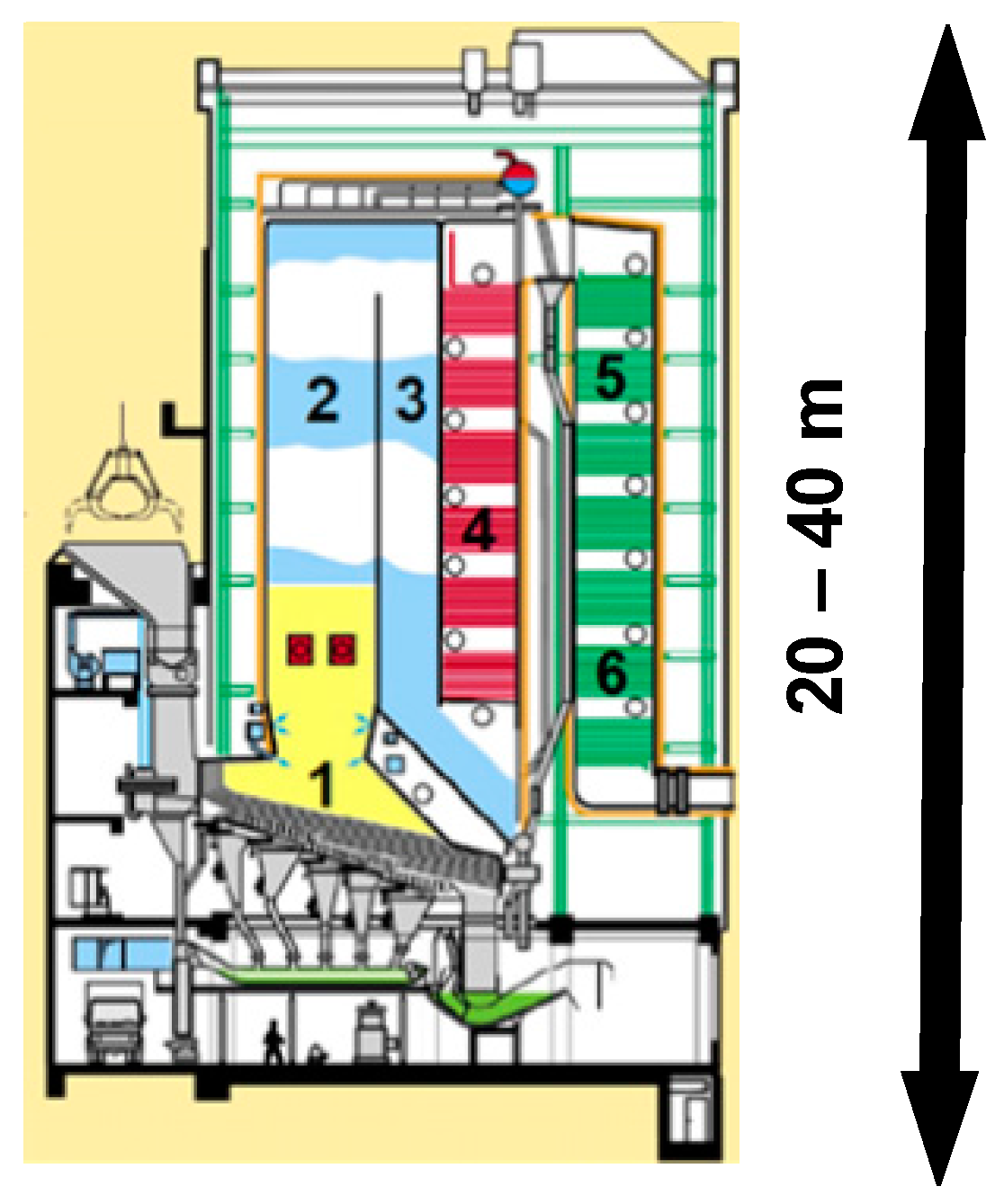
Applied thermal and aggressive loads in the coal-fired power plant are divided into groups due to the operating temperature, up to 800 °C, and the particulate content. In a gas corrosion medium, a small amount of particulate is present. In another typical group, the temperature drops, but the share of particulates increases. Various correlations between temperatures and particulate content cause changes in the wear type (gas corrosion, cavitation, abrasive, etc.). A typical incineration plant, shown in Figure 1, is subjected to similar loads, which are specified in Table 1.
Arc spraying is supremely suitable for protecting a large coating area due to the low operating costs and the simplicity of handling [9,10,11]. Active arc spraying (AAS) was applied for coating deposition in the present study. The process differs from a typical AS process by the use of propane-air combustion products as a carrier gas instead of compressed air. This increases the particle velocity and temperature and forms a reducing atmosphere in the arc burning zone. These features can decrease the burnout of spraying metal in flight, increase the adhesion strength of the coating, and lower the porosity of the coating [12,13].
Various Fe-based solid and cored wires are used as feedstock materials for the formation of coatings for wear- and heat-resistant applications.
Wear resistant coatings with a metastable austenite structure are of particular interest due to low alloying costs and high resistance in various conditions of mechanical wear (abrasion, impact, cavitation, etc.). Here, the energy of the external load which is applied to the working surface is dissipated due to the transformation of austenite to disperse martensite. This improves the reliability by synergetic combination of surface hardening and reducing internal stresses [14,15,16,17]. Pukasiewicz et al. showed that in Fe-Mn-Cr-Si arc-sprayed coatings cavitation resistance increased due to strain-induced martensite transformation [18].
Fe-Cr-Al alloys are traditionally used as bulk materials and as coatings for protecting against gas corrosion [19,20]. The heat resistance of the Fe-Cr-Al alloy is provided by a surface alumina layer, which forms at high operating temperatures. This oxide layer is characterized by a high melting temperature, chemical and thermal stability, and a low rate of growth [21]. Alloying the Fe-Cr-Al by B increases the wear resistance of the alloy by forming reinforcing carboboride phases [22]. Arc sprayed Fe-Cr-Al-B coatings save their protective properties when the erosion is combined with corrosion at elevated temperatures. The coatings demonstrate a 10–30-fold improvement in heat resistance at elevated temperatures of 600 and 700 °C compared with the steel 12Cr1MoV [23]. The addition of yttrium is favorable for protecting against gas corrosion and wear for the following reasons: First, Y-containing Fe-Cr-Al alloys showed good oxide adherence on the arc-sprayed coatings during operations undertaken at high temperatures under thermal cycling [24,25]. Second, during the AS process, alloying element burnout can take place. Yttrium’s affinity to oxygen is higher than that of other alloying elements [26]. Therefore, yttrium protects them from oxidation during the transition from the feedstock to the coating and preserves the ability of the alloying elements to resist against gas corrosion and wear.
A number of Fe-based cored wires for wear- and heat-resistant applications were developed [20,27,28] and patented with the participation of authors. The aim of the study was an analysis of wear- and heat-resistant properties of the coatings from the developed Fe-based cored wires.

2. Experimental Details

ASME 1020 steel were used as a substrate. An ADM-10 (UWI, Ekaterinburg, Russia) AAS gun was used for spraying the tested coatings. Current and voltage differed according to the type of test (see Table 2). The other employed parameters were kept constant: spraying distance 100 mm, input pressure of gases: air—0.34 MPa, propane—0.32 MPa, traverse velocity 200 mm/s.
A 1.5Cr8Ti2Al cored wire 1.6 mm in diameter was used as a feedstock in tests up to 200 °C. This alloy belongs to the metastable austenite type of alloy, which is used for increasing wear resistance via arc spraying [27]. The coatings were examined in an as-sprayed state and after additional rolling down of the surface, which was carried out via a “ball-on-plate” reciprocating technique. The test parameters were as follows: ball diameter: 10 mm; ball steel: E52100 ASTM (HRC 65); traverse speed: 0.16 m/s; stroke: 125 mm; friction path: 5 m; and axial load: 100 N, which corresponds to pressure of 2000 MPa [29]. This allows to reproduce loads sufficient for martensitic transformation in steels with metastable austenite [17].
Two Cr13Al5B5 cored wires 2.0 mm in diameter were used for high temperature tests. The composition of the second wire differs because of the alloying of yttrium. The Y content in the wire was designated according to the neural network model, which has been developed with respect to arc spraying [30]. The chemical composition of the cored wires is given in Table 3.
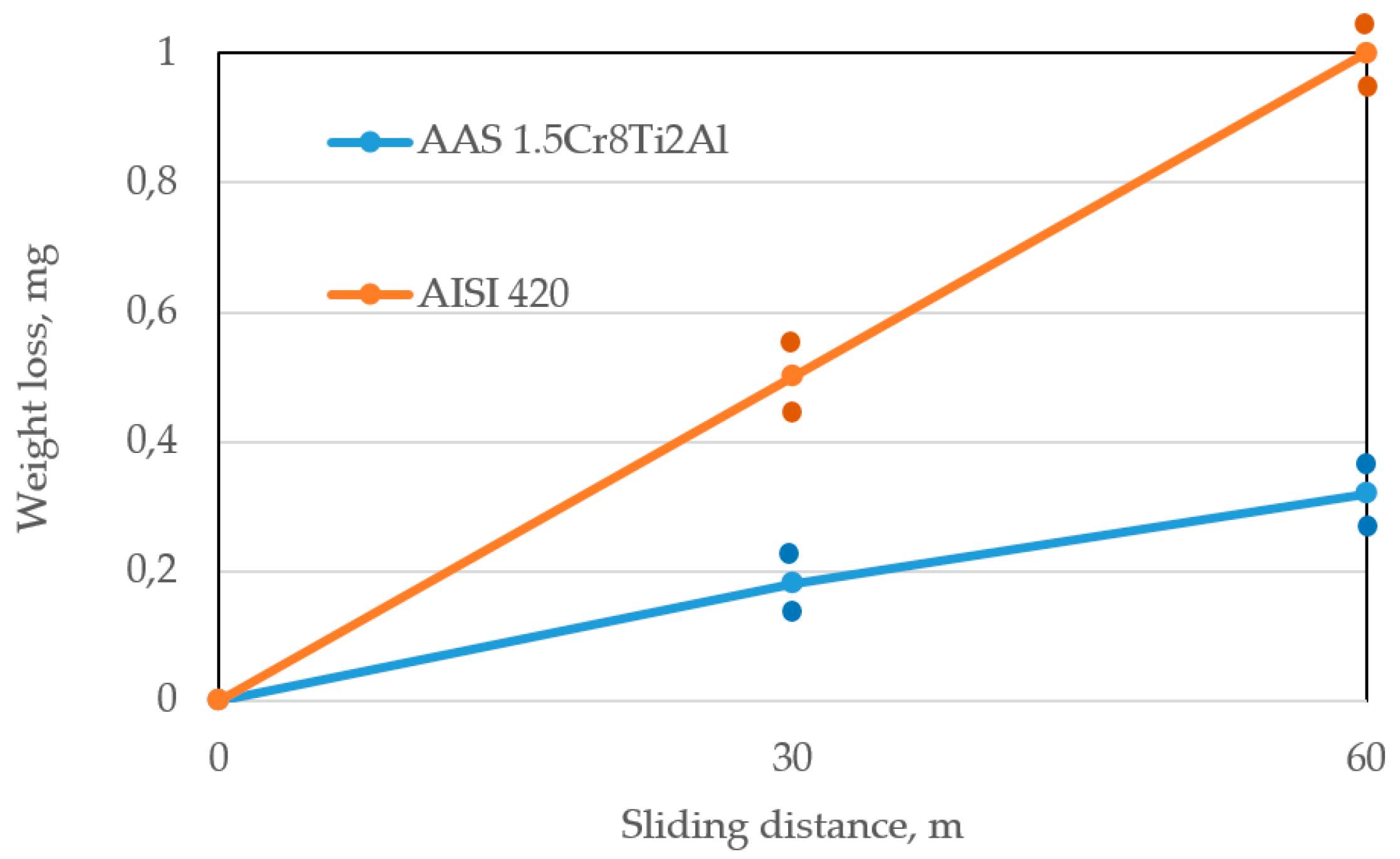
All coatings were subjected to a two-body abrasive test via the pin-on-plate reciprocating technique. Corundum abrasive paper with a grain size up to 150 μm, was fixed on the plate and the as-sprayed sample, 50 mm × 10 mm × 10 mm, was fixed in a holder. The test conditions were as follows: sliding distance: 60 m; pin velocity: 0.16 m/s; and specific load: 1 MPa. The pin is made of 1020 steel. To reduce the lapping period during the wear tests, the sprayed work surface area, 10 mm × 10 mm, on the pin was polished to Ra 0.8. A combination of corundum microhardness 22.900 MPa [31] and a specific load of 1 MPa provide the scratching abrasive wear. This type of test was chosen for the following reasons:
  • This type of wear is most easily reproduced in the laboratory and can be easily unified. Therefore, reference data on the relative wear resistance of various materials are comparable;
  • Other types of abrasive wear (hydro- and gas-abrasive, shock-abrasive, and thermal-abrasive ones) also realize the same kind of surface failure with applying additional loads. The row of relative wear resistance, obtained with scratching abrasive wear, is reproduced in other types of abrasive wear if microcutting is the main mechanism of surface failure during wear [32,33].
For wear-resistant coatings, the following studies were performed. Microhardness was measured with a PMT-3 device (LOMO, St. Petersburg, Russia) under a 100 g load. The load was assigned ensuring the ratio (indentation depth)/(coating thickness) < 0.1 [34]. To verify, microhardness measurements were made with a successive decrease in the load, 0.981, 0.49, and 0.196 N. The deviations of the average values of the corresponding series from five measurements of each did not exceed 4%. The coating structure was studied with a MET 2 microscope (Altami, St. Petersburg, Russia), a DRON-3.0 X-ray diffractometer (Bourevestnik Inc., St. Petersburg, Russia) in Fe- and Co- Kα radiation, and a Philips SEM 525 scanning electron microscope (FEI, Hillsboro, OR, USA).
The following studies were performed to evaluate the heat-resistant coatings. The amount of oxygen in the coating was measured by melting the coating in an inert gas flow with an ON-900 analyzer (Eltra, Haan, Germany). The porosity of the coatings was determined via the metallographic method on the transverse sections using commercial SIAMS 700 hardware and software (SIAMS, Ekaterinburg, Russia) to estimate the distribution of pores by size, area, and volume. The results of the porosity determination were averaged for the five fields of view in accordance with ASTM E2109-01(14).
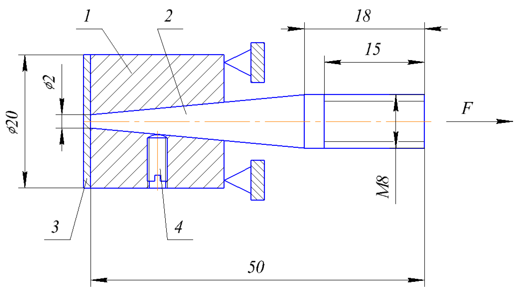
The adhesion strength of the coatings was determined by the separation of a conical pin. A schematic view of the test is presented in Figure 2. Here, washer 1 serves as the base; pin 2 is inserted into the hole so that its end face is flush with the external plane of the washer. The pin is fixed by screw 4. The total surface of the pin and the washer after preparation is coated with coating 3. The test consists of pulling the pin by applying force (F). The quantitative characteristic of the adhesive strength is the ratio of the maximum applying force to the pin face area. The results were averaged from three samples. The method is characterized by the versatility and high-speed performance. In case of a pin end diameter of 2 mm and a coating thickness of more than 300 μm, reliable results are possible [34].
The heat resistance of the coatings from these wires was evaluated in accordance with GOST 9.312 [35]. The gravimetric method was used according to the weight-loss measurements of samples exposed for 100 h in air at 700 °C. To decrease measuring errors, the 30 mm × 20 mm × 3 mm samples were deposited with a 10 μm galvanic nickel layer in order to protect the sample from non-controlled oxidation at elevated temperatures. A special evaluation of the heat resistance of the galvanized Ni were not carry out. However, oxidation of Ni and Fe differ as follows: A passivizing oxide film is formed on a Ni surface at 635 °C, and it is preserved up to 1200 °C [36]. On the Fe surface, at a temperature above 572 °C, the film is mainly composed of wuestite, which has weak protective properties due to the predominant diffusion of Fe [37]. After the exposition there were no signs of disturbance of the Ni oxide film. Before spraying, the layer from one side of the specimen surface (30 mm × 20 mm) was removed by grinding. This side was subjected to grit blasting with corundum sand; after that, the arc-spray coatings with a thickness of 700 μm were deposited. The galvanized surfaces were not specially prepared, so the coating that formed on them was easily removed. The sprayed surface was ground to a thickness of 400 μm.
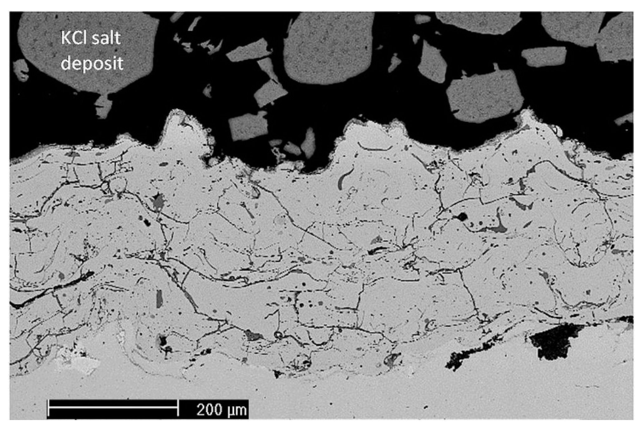
The high-temperature corrosion test was performed in an alumina tube furnace at 550 °C for a duration of 168 h. The coating samples on ASME 1020 steel were cut to a size of 20 mm × 20 mm, while an area of about 255 mm2 (an 18 mm-diameter circle) was covered with approximately 1 g of KCl salt. The salt was finely ground in a ceramic mortar and mixed with ethanol to create a paste and facilitate the deposition. The furnace environment was purged with 1.5 L/min of air with the addition of water vapor to reach 12% of the specific humidity.
Microhardness measurements were performed with a Leica VMHT device (Walter Uhl, Aßlar, Germany) under 50 and 300 g loads. When measuring the average hardness value before wear testing, a load of 300 g is taken. After the wear tests, it is important to evaluate the microhardness of the thinner surface layer subjected to friction hardening. This requires a smaller load on the indenter [34] and a procedure of verifying the test results was carried similar to wear-resistant coatings.
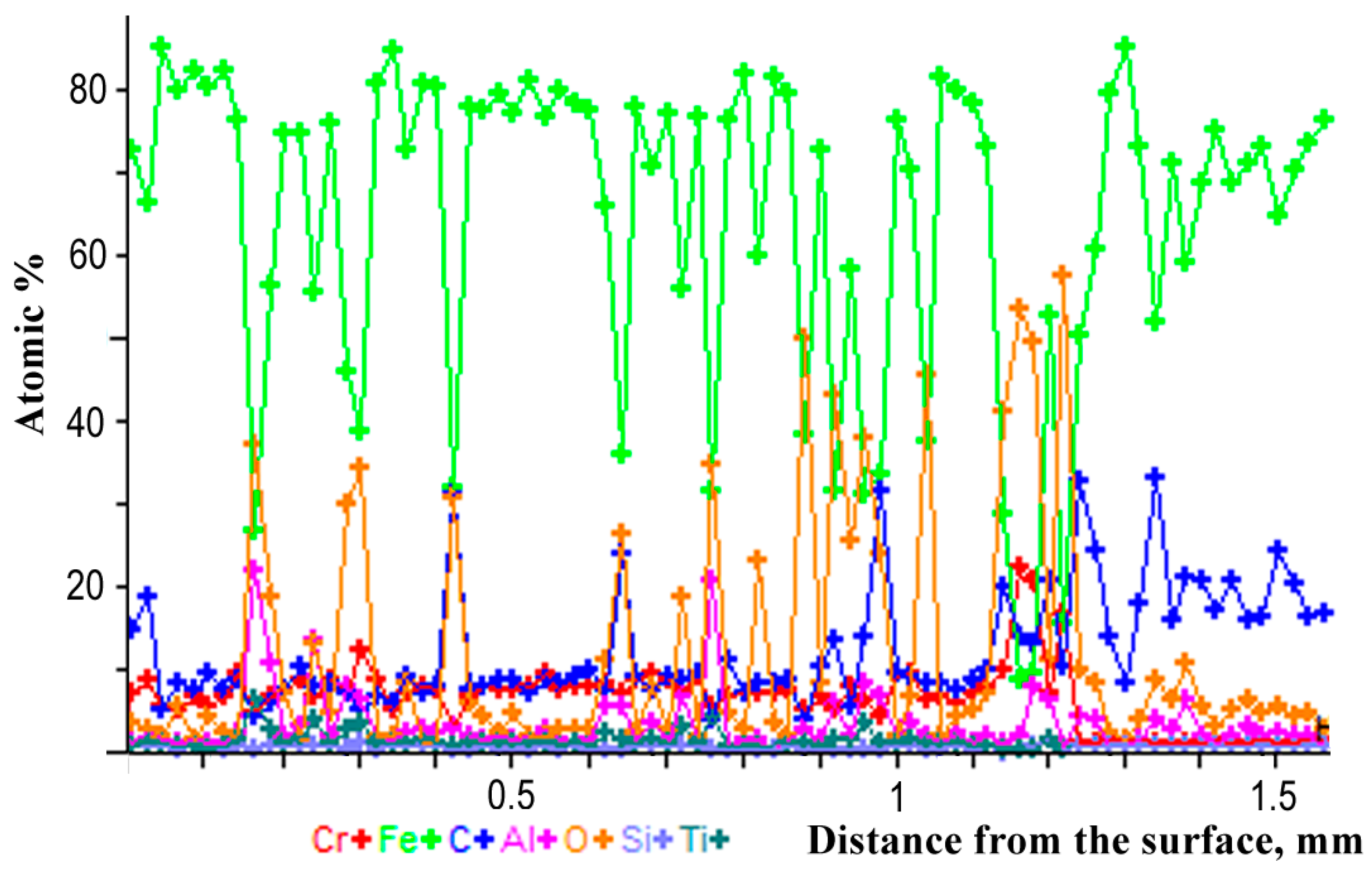
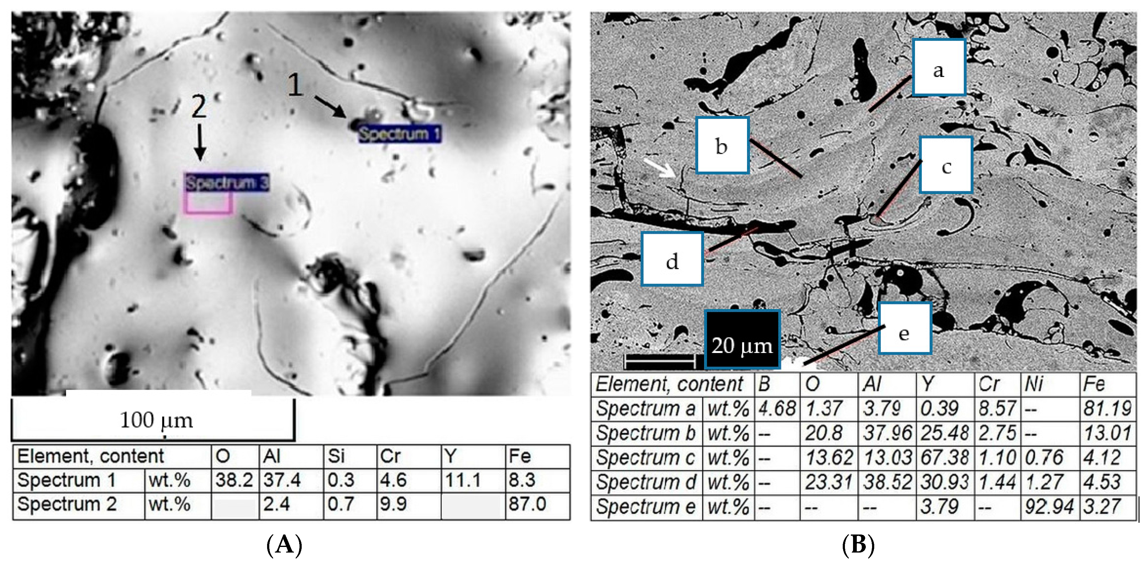
A microstructural study of the as-sprayed coating from a Y-containing wire was performed as follows: Phase composition on the coating surface was determined by a XRD-7000 X-ray diffractometer (SHIMADZU, Kyoto, Japan, Cr-Kα radiation). The microchemical structure and composition of the coatings was studied with a VEGA II XMU scanning electron microscope (Tescan, Brno, Czech Republic). It was equipped with an INCA Wave 700 wavelength dispersive X-ray spectrometer and INCA Energy 450XT microanalyzers (Centre “Plastometria”, the Institute of Engineering Science, Ural Branch of RAS, Ekaterinburg, Russia).
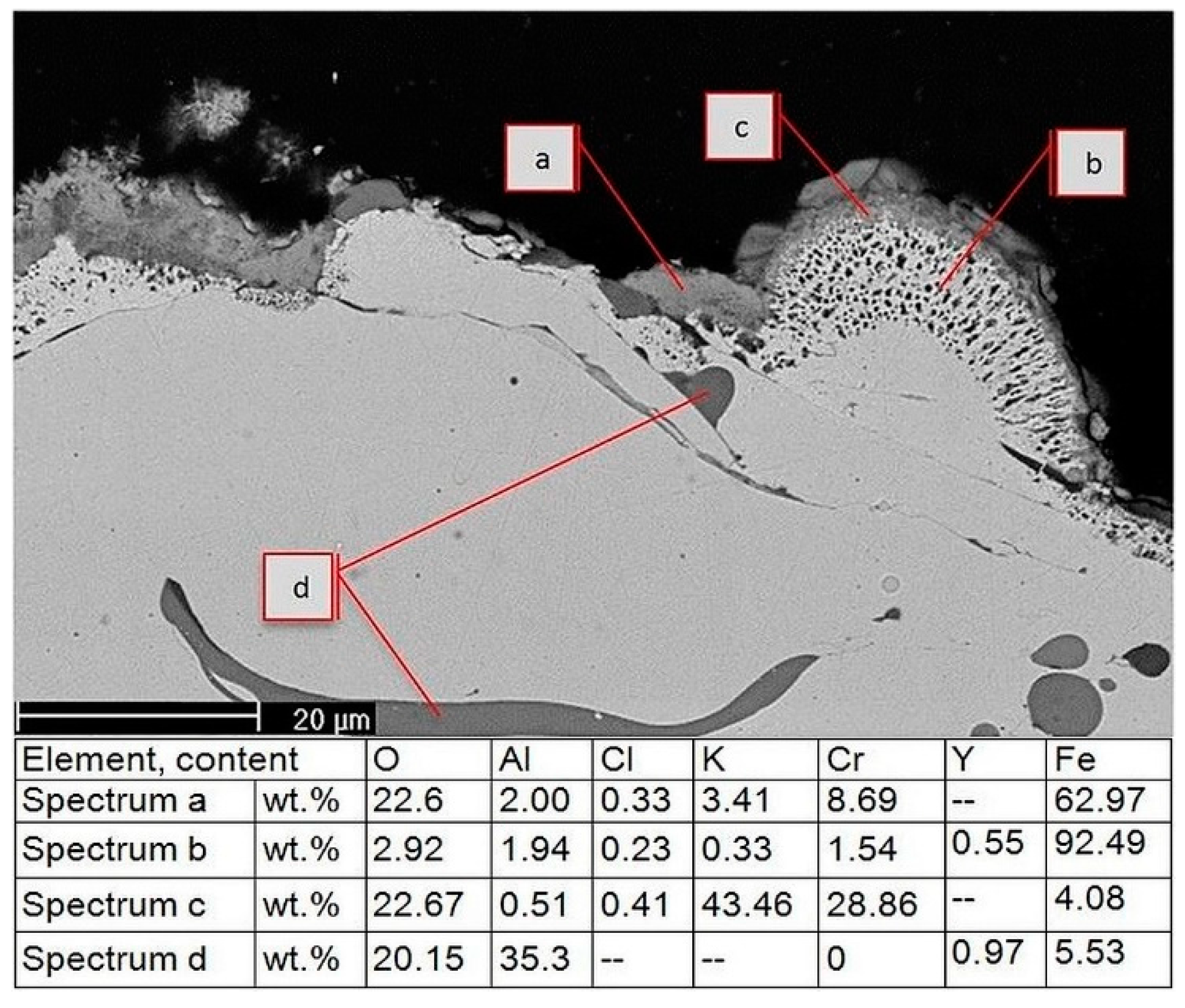
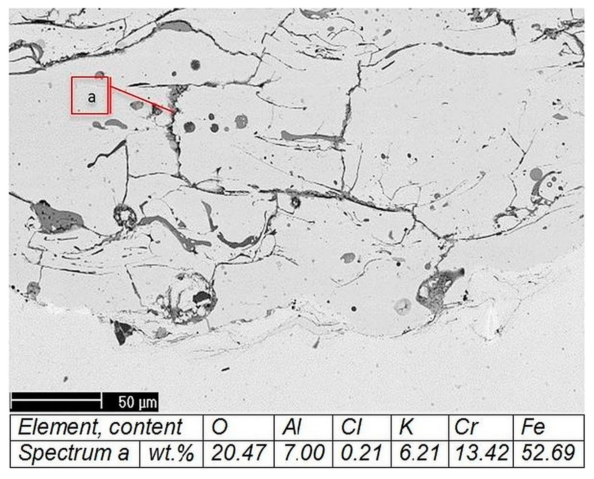
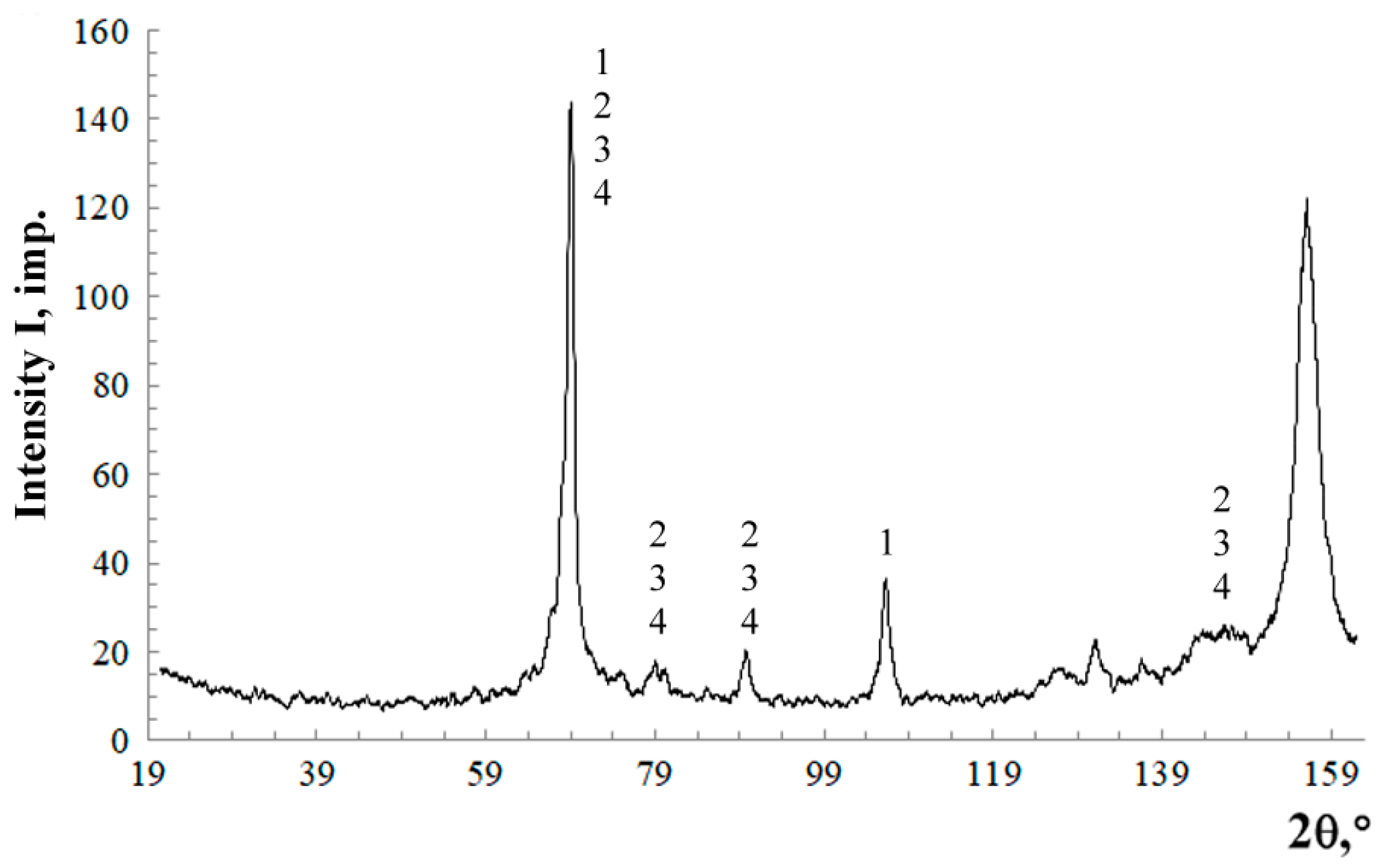
The microstructure of the coating after a corrosion test from an AAS-Y wire was investigated via a scanning electron microscope (SEM) and a microanalysis of the cross-section was studied with a Philips XL30 equipped with an energy dispersive X-ray (EDX). Phase composition was assessed by X-ray diffractometry (XRD, Empyrean, PANAnalytical, Co-Kα radiation, the wavelength is 1.79021 Å) of the surface of the coating. The experimental conditions include the scanning range from 20° to 120° in 2θ, at a scanning step rate of 0.02°, a beam mask of 20 mm, a programmable divergent slit fixed at ½ degree, a Fe-filter, and a PANAnalytical PIXcel 3D detector (Malvern Panalytical B.V., Almelo, The Netherlands). Phase identification was performed using the PANAlytical X’Pert High Score Plus software (version 4.0) using the ICDD JCPDF-2 database (International Centre of Diffraction Data, Newtown Square, PA, USA).

3. Results

3.1. Wear-Resistant Coatings from a 1.5Cr8Ti2Al Cored Wire

3.1.1. Microstructure of the As-Sprayed Coatings

The metallographic analysis of the transversal microsections of the coatings has shown that the structure of the coating has a wave-like nature in the arrangement of the structural components (Figure 3). Etching reveals inclusions of metal oxide complexes of various shades of gray. This corresponds to a change in the reflectivity of the complexes, depending on the metal-oxide ratio. At the ‘coating-substrate’ interface there are thin oxide films with rare thickenings and an insignificant quantity of pores. The fragment pieces of the coating microstructure on the surface are multicolored and their sizes are in the range of 10–50 μm. They have irregular or rectangular shapes.
The SEM analysis of the coating surface showed that light fields contain Fe (bal.), Cr (6–10 wt %), and a negligible quantity of Ti. These metal fragments represent a solid solution of Cr in austenite and martensite. The gray-colored fragments contain the maximum concentration of the alloying elements Cr (10–12 wt %) and Ti (2–3 wt %) (Fe bal.). These gray areas are likely complexes of carbides and oxides.
The X-ray diffraction analysis of the coating surface showed that the phase structure is based on metal (70 vol %). It consists of martensite and retained austenite in a 50/50 ratio, vol %. According to the EDX analysis on the SEM (Figure 4), it can be stated that the main phase of the coating is a solid solution of alloying elements based on Fe. The oxides of different compositions, like Al2O3, Cr2O3, SiO2, and (Al, Ti)2O3, are unevenly distributed in the solid solution. Additionally, there are separate particles of chromium carbide in the coating.
Thus, light fragments are comprised of a metal base, gray ones are comprised of carbides (i.e., Ti, Cr), and dark ones are comprised of Fe oxides.

3.1.2. Microhardness, Phase Composition, and Wear Resistance after Ball Rolling

Measurements of the coating surface after the ball-on-plate test showed that the microhardness rises from 600 ± 62 HV0.1 before loading to 770 ± 48 HV0.1 after the first rolling and 880 ± 42 HV0.1 after the second rolling. The change in microhardness after multiple loadings by ball rolling was accompanied by a reduction in the amount of austenite in the metal matrix, as shown by the X-ray analysis. The measurement of the austenite-martensite ratio was made by estimating the integral intensities of the diffraction lines obtained from the corresponding crystallographic planes of the phases (110)α and (111)γ. According to the phase calculation by the XRD-7000 diffractometer software, the amount of austenite dropped noticeably after ball rolling of the surface. However, after the wear test, the martensitic transformation took place to a greater extent than after the ball rolling (Table 4). Wear tests confirmed an influence of martensitic transformation. They showed that the wear resistance of AAS coating from a 1.5Cr8Ti2Al cored wire is three times larger compared to the arc-sprayed coating from an AISI 420 (X20Cr13) solid wire (Figure 5).

3.2. Heat-Resistant Coatings from AAS and AAS-Y Cored Wires

3.2.1. Oxygen Inflow during the Spray Process

Measuring the amount of oxygen in the coating showed that the oxygen content in the AAS-Y coating (1.3 wt %) is 1.8 times less compared to the AAS coating. This result coincides with the side data, according to which the oxygen content in the arc-sprayed coatings is cut in half by the introduction of rare earth metals into cored wires [24].

3.2.2. Adhesion Strength and Porosity

In the AAS-Y coating, adhesion strength is 43 ± 3 MPa, and its mean value is 1.2 times higher than that of the coating prepared from the AAS wire.
The porosity of the AAS coating is 25% higher, while the range of the diameters of pores is slightly lower, in comparison with the AAS-Y coating (see Table 5). The pore distribution is similar in both cases (see Table 6).

3.2.3. Heat Resistance

The measured specific weight-loss for the AAS-Y coating is an order of magnitude smaller than those of T11 and T122 steels and is similar to the heat resistance of austenite steel during the heat resistance test. In addition, its specific weight-loss is lower by 20% in comparison with AAS coating (Table 7).

3.2.4. Wear Resistance of the Coatings

The microhardness of the AAS-Y coating was HV0.3 1111 ± 64 before the wear test and HV0.05 1222 ± 52 after the wear test. The weight loss of the AAS-Y samples after tribological tests was in the range of 0.15–0.19 g. The AAS-Y coating was compared with an AAS arc-sprayed coating from a 1.5Cr8Ti2Al cored wire, which was studied before, and ASME 1020 solid steel. The results showed that the wear resistance of an AAS-Y coating is higher compared to the examined alternatives (Table 8).
As shown, the AAS-Y coating is better by the criteria of oxygen content, porosity, hardness, and wear- and heat-resistance. Therefore, further studies were focused on these coatings.

3.2.5. Structure of the As-Sprayed Coatings

The surface SEM results mainly showed spectra corresponding to the basic coating components, i.e., Fe, Cr, Al (spectrum 2), in the presence of spectra corresponding to the precipitation of mixed spinel-type oxides, like (Al, Y)2O3 (spectrum 1) (Figure 6A).
Si was not especially added: it exists only as an impurity. A cross-section of the AAS-Y coating is shown in Figure 6B. The zones marked as (a–e) were detected by EDX microanalysis. The different grey-scale colored striations (a,b) differ according to the content of Al and Y. In particular, darker striations have significant amounts of Al and Y. Small cracks were detected along the boundaries of such zones (white arrow). Some small dark grey drop-like inclusions (c) are plentiful in Y and Al. Pores (d) are present in the coating. On the coating-substrate interface, several white, long inclusions of a size of about 100 µm were observed (e). These large inclusions are Ni-rich, which could be residual material from the galvanic Ni layer.
According to the surface analysis, the coating from the AAS-Y wire consists of iron α-phase (solid solution of Fe-Cr-B, enriched with carbon) with reinforcing phases: borides Fe2B (Fe,Cr)2B and carboborides (Fe,Cr)2(B,C) (Figure 7).

3.2.6. Corrosion Resistance of the AAS-Y Coating

An overall image of the coating after the test and corrosion products is presented in Figure 8. A homogeneous thin corrosion product layer was detected on top of the coating.
A magnification of the corrosion products is given in Figure 9. EDX microanalysis showed the following: A homogeneous thin corrosion product layer was detected on top of the coating. The topmost corrosion product layer (a) is rich in metal oxides, probably in the form of chromates and ferrates of potassium. A thin porous layer lies between the corrosion products and coating (b). The EDX spot analysis in the pores (c) indicates the presence of Cr, Y, and Al. The high amount of Fe probably belongs to the coating. This porous morphology might be a precipitation zone of borides, which was subjected to selective corrosion of Cr, as the XRD analysis suggests.
This type of morphology may be caused by chlorine-induced corrosion [40]. Chlorine can selectively react with alloying elements and precipitates, like borides and carbides, forming volatile chlorides that leave the surface in the form of a vapor, resulting in a porous area. The formed chlorides then migrate toward the surface, where the higher partial pressure of oxygen makes them deposit in the form of oxides [41]. The chromium oxide in the layer lying on top of the porous area (c) probably originated in such a way. Several inclusions of different shapes and sizes were detected (d). The presence of Al and Y oxides has been revealed in these inclusions.
Along the coating cross-section, the multiple cracks are filled with Fe, Cr, and Al oxides (Figure 10). The coating is well bonded to the substrate. However, some cracks are visible, and metal oxides, including Fe, Cr, Al, and a very small amount of Cl, were detected (Figure 10, area a). The very minor presence of chlorine along the coating cross-section might be induced by the sample preparation procedure. However, the high number of cracks is a possible pathway for chlorine to propagate and, therefore, further studies are required to verify the effectiveness of the coating protection. A very thin corrosive product layer is formed on the surface of the coating, as in the case of a Ni-based arc-sprayed coating tested under similar conditions [42].

4. Discussion

4.1. Wear-Resistant Coatings with a Metastable Austenite Structure

The coating structure forms under the rapid cooling of the sprayed particles on the substrate. The cooling rate of the coating is 104–105 °C/s. [43]. Thus, the crystallization corresponds to a high rate type which occurs via diffusionless transformation. This type of crystallization is characterized by the delayed precipitation of carbides from the solution [44]. The primary carbides and eutectics are absent in the structure of the as-sprayed coatings. Only secondary carbides, allocated from the austenite after crystallization, are present in the structure. They are about an order of magnitude smaller than the primary carbides [45]. This reduces the tendency of the coatings to crack.
As is known, previous droplets solidify 2–3 orders faster than new molten droplets impacting the substrate, even at maximum spraying capacity [43,46]. Thus, the strain-induced martensite nucleation on each surface layer is facilitated by the impact of droplets during the formation of the coating. Due to the specific features of the coating formation, the share of martensite in the coating structures is increased in comparison with the arc surfaced layer from the cored wire of the same composition [28].
The behavior of the metastable retained austenite in the sprayed coating is the same as in solid TRIP-steels. At contact load, the retained austenite quantity is lowered by 2–3 times and the deformation of martensite occurs. Thus, the wear resistance of the coating improves via the following synergetic effects:
  • Internal stresses in the coating drop due to the change in the crystal lattice volume;
  • The energy of the contact load is dissipated by the strain-induced nucleation of martensite; and
  • Surface hardening takes place.

4.2. Heat-Resistant Coatings from a FeCrBAlY Cored Wire

The present study showed that the oxygen content in the coating reduced upon the addition of yttrium and the content of the oxide layer changed. This is probably due to the higher affinity of yttrium with oxygen compared to aluminum. The free Gibbs energy of the formation of oxides of alloying elements is as follows: Y2O3 −1300 kJ/mol; Al2O3 −1120 kJ/mol [26]. Applying the addition of yttrium to the Fe-Cr-Al bulk alloys results in the following [47,48]: improved oxidation resistance and oxide adherence.
Analysis of the influence of yttrium on the properties of the Fe-Cr-Al-Y arc-sprayed coatings requires further research. However, based on the results and analogies with bulk metal the following conclusions can be drawn:
  • Yttrium prevents the burnout of other alloying elements during spraying. Thus, the proper content of the alloying elements has been maintained for further operations.
  • An increase in the coating’s oxidation resistance is associated with the formation of complex oxides, such as (Fe, Al, Y)2O3.
  • The lower degree of oxidation causes an increase in the adhesion strength and a reduction in porosity. This can be explained by a decrease of the oxide layer on sprayed particles in flight. As shown by Sobolev and Guilemany, oxidation decreases the pressure developed upon the droplet impact that is detrimental to the contact between the substrate and splat [49].
  • Prevention of the aluminum oxidation with yttrium during spraying causes an amplification of aluminothermic reactions. It leads to a more uniform melting of boron-containing components and the formation of a denser coating structure. Additionally, this was confirmed by previous studies [22]. As a result, wear resistance increased by 20%.
The microhardness of the coatings from the cored wires of the Fe-B-Cr alloying system is 1.5–1.8 times as high, and the wear resistance is more than twice as high in comparison with wear-resistant 1.5Cr8Ti2Al coatings with a metastable austenite structure. Obviously, borides of the (Fe, Cr)2(B, C) type, which form in the first case, are more effective as strengthening phases in abrasive wear than martensite and chromium carbides in the second case.
An increase in the order of wear resistance of the AAS-Y coating, in comparison with ASME 1020 solid steel, indicates that this coating is a good solution for protecting parts from abrasive wear.
Chlorine-induced corrosion takes place mainly on the surface of the coating from the yttrium-added wire. The corrosion product thickness on the surface of the coating is quite low and of the same magnitude as the comparable Ni-based arc-sprayed coatings tested under similar conditions.

5. Conclusions

Cored wires of the base alloying system Fe-Cr-C were used as a feedstock for arc spraying. They included 1.5Cr8Ti2Al cored wire and two Cr13Al5B5 cored wires. One of the last was additionally alloyed by yttrium. The coatings were investigated in the range of 20–700 °C. The studies comprise the following: wear and heat resistance tests, microhardness measurements, high-temperature corrosion testing, porosity and adhesion strength evaluation, and SEM and XRD analyzes.
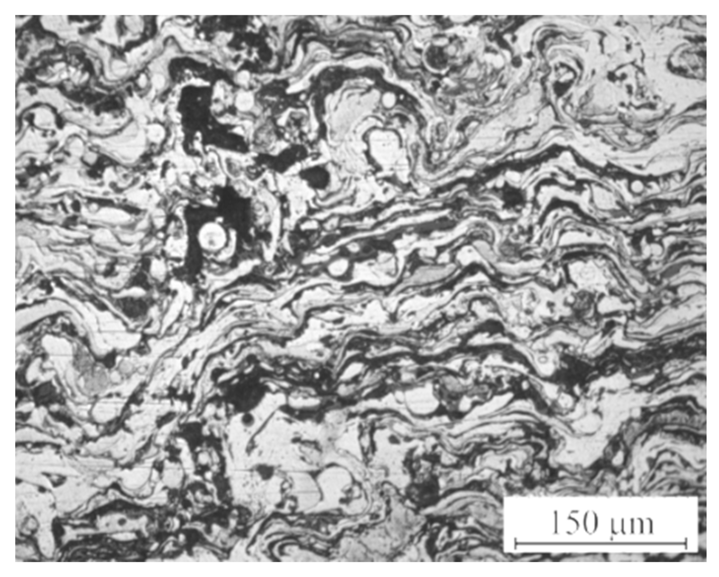
A metastable austenite structure forms in the coating from 1.5Cr8Ti2Al cored wire. As a result, after loading at room temperature, a share of the martensitic phase rises. The strain-induced martensite nucleation on each surface layer is facilitated by the impact of droplets during the formation of the coating.
This leads to an increase of abrasive wear resistance, which is three times larger compared to the arc-sprayed coating from the AISI 420 (X20Cr13) solid wire. Thus, the wear resistance of the coating improves via the following synergetic effects:
  • Internal stresses in the coating drop due to the change in the crystal lattice volume;
  • The energy of the contact load is dissipated by the strain-induced nucleation of martensite;
  • Surface hardening takes place.
Addition of yttrium to the Cr13Al5B5 coating results in the following, as compared to the Y-free coating:
  • Oxygen content is 1.8 times less, which indicates a lowering of the burnout of other alloying elements during spraying, Thus their proper content is saved for further operations;
  • The formation of complex oxides like (Fe, Al, Y)2O3 leads to an increase in the coating’s oxidation resistance by 20%;
  • Adhesion strength is 1.2 times higher and the porosity drops by 25% due to less oxidation of sprayed particles in flight; and
  • Wear resistance increases by 20% due to an influence of amplified aluminothermic reactions on the uniformity of boron-containing components melting and the coating density.
Borides of the (Fe, Cr)2(B, C) type, which form in the case of the Cr13Al5B5 coating, are more effective as strengthening phases at abrasive wear than martensite and chromium carbides in the case of the 1.5Cr8Ti2Al coating. Consequently, the wear resistance in the former case is twice as high as in the latter one.
Chlorine-induced corrosion takes place mainly on the surface of the coating from the yttrium-added Cr13Al5B5 wire. Corrosion product thickness on the surface of the coating is quite low and of the same magnitude as the comparable Ni-based arc-sprayed coatings tested under similar conditions.
Values of wear- and heat resistance of the coating from the yttrium-added Cr13Al5B5 cored wire are an order of magnitude higher than those of pearlite and martensite-ferritic steels that are typical for boiler applications.
Economically alloyed Fe-Cr-C-based arc sprayed coatings can be applied in wear- and heat-resistant conditions in the range of 20–700 °C. Possible applications in power engineering include protection of the parts of fossil energy systems and waste incinerators.

Acknowledgments

The authors would like to thank Valentin Shumiakov, Stanislav Nevezhin, and Vadim Verkhorubov (Ural Federal University, Ekaterinburg, Russia) for valuable technical information and comments. The present study was supported by FASIE, program Development-NTI 2017, project no. 0035960.

Author Contributions

Yury Korobov and Petri Vuoristo conceived and designed the experiments; Irina Malygina, Natalia Soboleva, Milanti Andrea, and Davide Fantozzi performed the experiments; Michael Filippov, Aleksey Makarov, Heli Koivuluoto, and Davide Fantozzi analyzed the data; Irina Malygina and Korobov Yury provided the reagents/materials/analysis tools. All authors contributed to the preparation of the manuscript.

Conflicts of Interest

The authors declare no conflict of interest. The founding sponsors had no role in the design of the study, in the collection, analyses, or interpretation of data, in the writing of the manuscript; or in the decision to publish the results.

References

  1. Kakaras, E. Current situation of coal fired power plants in Russia federation and the implementation options of clean coal technologies. In Proceedings of the 5th European Conference on Coal Research & Its Applications, Edinburgh, UK, 6–8 September 2004. [Google Scholar]
  2. Mäkipää, M.; Pohjanne, P. Review of recovery boiler superheater material studies. In Proceedings of the 50th Anniversary International Recovery Boiler Conference, Tampere, Finland, 11 June 2014. [Google Scholar]
  3. Gooch, D.J. Materials issues in renewable energy power generation. Int. Mater. Rev. 2000, 45, 1–14. [Google Scholar] [CrossRef]
  4. Spiegel, M. Salt melt induced corrosion of metallic materials in waste incineration plants. Mater. Corros. 1999, 50, 373–393. [Google Scholar] [CrossRef]
  5. Krause, H.H.; Wright, I.G. Boiler tube failures in municipal waste-to-energy plants. Mater. Perform. 1996, 35, 46–53. [Google Scholar]
  6. Oakey, J.E.; Minchener, A.J.; Hodges, N.J. The use of high-chlorine coals in industrial boilers. J. Inst. Energy 1991, 13, 3–11. [Google Scholar]
  7. Ots, A.A. Corrosion and Wear of Boiler Heating Surfaces; Energoatomizdat: Moscow, Russia, 1987. [Google Scholar]
  8. Wilden, J.; Jahn, S.; Reich, S. Production of high quality anti-corrosion and wear-resistant wire arc sprayed coatings. In Thermal Spray 2008: Thermal Spray Crossing the Borders on CD-ROM; Lugscheider, E., Ed.; DVS-German Welding Society: Maastricht, The Netherlands, 2008. [Google Scholar]
  9. Tillmann, W.; Hagen, L.; Duda, D. A Study on the Tribological Behavior of Arc Sprayed Vanadium Doped Stellite Coatings. In Proceedings of the International Thermal Spray Conference (ITSC 2017), Düsseldorf, Germany, 7–9 June 2017; pp. 354–359. [Google Scholar]
  10. Davis, J.R. Handbook of Thermal Spray Technology; ASM International: Almere‎, The Netherlands, 2005. [Google Scholar]
  11. Guo, X.C.; Huang, Q.; Hu, J.L.; Ke, F.H.; Wu, S.H.; Yin, S.; Ye, L.; Ze, K.L.; Yi, L.S. Applications and development trends of thermal spraying technologies for power plant equipment remanufacturing engineering. In Proceedings of the Fifteenth International Conference on thermal spraying (ITSS’2012) & the sixteenth national annual meeting of thermal spray (CNTSC’2012), Xuzhou, China, 23 October 2012; pp. 83–88. [Google Scholar]
  12. Boronenkov, V.; Korobov, Y. Fundamentals of Arc Spraying. Physic-chemical Regularities; Springer International Publishing: Cham, Switzerland, 2015. [Google Scholar]
  13. Korobov, Y. Efficiency of using activated arc metallization for the deposition of protective coatings. Weld. Int. 2005, 19, 580–582. [Google Scholar] [CrossRef]
  14. Bogachev, I.N.; Mintz, R.I. Cavitation Destruction of Iron-Carbon Alloys; Mashgiz: Moscow-Sverdlovsk, Russia, 1959. [Google Scholar]
  15. Bogers, A.J.; Burgers, W.G. Partial dislocations on the {110} planes in the b.c.c. lattice and the transition of the f.c.c. into the b.c.c. lattice. Acta Metall. 1964, 12, 255–261. [Google Scholar] [CrossRef]
  16. Olson, G.B.; Cohen, M.A. Mechanism for the strain-induced nucleation of martensitic transformation. J. Less-Common. Metals 1972, 28, 107–118. [Google Scholar] [CrossRef]
  17. Filippov, M.A.; Litvinov, V.S.; Nemirovski, Y.R. Steels with Metastable Austenite; Metallurgy: Moscow, Russia, 1988. [Google Scholar]
  18. Pukasiewicz, A.G.M.; Capra, A.R.; Paredes, R.S.C. Development of arc thermally sprayed Fe-Mn-Cr-Si coatings against cavitation erosion. In Proceedings of the International Thermal Spray Conference & Exposition ITSC 2011, Hamburg, Germany, 27–29 September 2011. [Google Scholar]
  19. David, J.Y. High Temperature Oxidation and Corrosion of Metals, 2nd ed.; Elsevier: ‎Amsterdam, The Netherlands, 2016. [Google Scholar]
  20. Korobov, Y.; Filippov, M.; Nevezhin, S.; Karabanalov, M. High-Temperature Oxidation Behavior of Fe-25Cr-5Al Arc Spraying Coatings. In Proceedings of the International Thermal Spray Conference and Exposition (ITSC) 2012 American Society for Metals, Houston, TX, USA, 21–24 May 2012; pp. 729–733. [Google Scholar]
  21. Sims, C.T.; Stoloff, N.S.; Hagel, W.C. Superalloys II: High-Temperature Materials for Aerospace and Industrial Power; John Willey and Sons: New York, NY, USA, 1987. [Google Scholar]
  22. Borisova, A.L.; Mits, I.V.; Kaida, T.V.; Kleiman, A.S. Structure and properties of coating based on ferrochrome and ferrochrome aluminum alloys obtained by arc spraying flux-cored wires. Avtom. Svarka 1995, 6, 3–6. [Google Scholar]
  23. Wielage, B.; Pokhmurska, H.; Student, M.; Gvozdeckii, V.; Stupnyckyj, B.; Pokhmurskii, V. Iron-based coatings arc-sprayed with cored wires for applications at elevated temperatures. Surface Coat. Technol. 2013, 220, 27–35. [Google Scholar] [CrossRef]
  24. He, D.; Jiang, J. Effect of Rare Earth Elements on the Wear Resistance of Iron-Based Thermal Sprayed Coatings. In Proceedings of the Thermal Spray 2004: Advances in Technology and Application, Osaka, Japan, 10–12 May 2004; pp. 61–64. [Google Scholar]
  25. Amano, T. Rare earth application for heat-resisting alloys. J. Rare Earth 2010, 28, 12–21. [Google Scholar] [CrossRef]
  26. Kulikov, I.S. Metal Deoxidation; Metallurgy: Moscow, Russia, 1975. [Google Scholar]
  27. Korobov, Y.; Filippov, M.; Belozertsev, A.; Neveszin, S.; Shymiakov, V. Metastable austenite type core wire for arc spraying—Modeling of heat transfer in end face and coating structure analysis. In Proceedings of the Thermal Spray 2010: Global Solutions for Future Applications, Singapore, 3–5 May 2010; pp. 631–635. [Google Scholar]
  28. Korobov, Y.; Filippov, M.; Makarov, A.; Zabolotski, I.; Khudorozhkova, Y.; Rimer, G. Comparison of metastable austenite type structure of Fe-based coatings produced by arc spraying and surfacing. In Proceedings of the Thermal Spray 2014: Not Fiction: Thermal Spray the Key Technology of Modern Life! Barcelona, Spain, 21–23 May 2014; pp. 874–878. [Google Scholar]
  29. Elagina, O.Y. Technological Methods to Improve the Wear Resistance of Machine Parts; Logos: Moscow, Russia, 2009. [Google Scholar]
  30. Korobov, Y.; Nevezhin, S.; Verkhorubov, V.; Rimer, G.; Zhilin, A. Optimization of alloying of heat resistant core wires for arc spraying by neural network modeling. In Proceedings of the 5th International Conference on Thermal Process Modeling and Computer Simulation, Orlando, FL, USA, 16–19 June 2014; pp. 322–327. [Google Scholar]
  31. Patnaik, P. Handbook of Inorganic Chemicals; McGraw-Hill: New York, NY, USA, 2002. [Google Scholar]
  32. Garkunov, D.N. Tribotechnics (Wear and Wear-Free State); MSKHA: Moscow, Russia, 2001.
  33. Belyi, V.A.; Ludema, K.C.; Myshkin, N.K. Tribology in the USA and the Former Soviet Union; Allerton Press: New York, NY, USA, 1994. [Google Scholar]
  34. Tushinsky, L.; Kovensky, I.; Plokhov, A.; Sindeyev, V.; Reshedko, P. Coated Metal: Structure and Properties of Metal-Coating Compositions; Springer: Berlin, Germany, 2002. [Google Scholar]
  35. GOST 9.312 Unified System of Corrosion and Ageingprotection. Protection Coatings. Methods of Heat Resistance Determination; USSR State Committee on Standards: Moscow, Russia, 1989.
  36. Evans, Y.R. Corrosion and Oxidation of Metals; Metallurgizdat: Moscow, Russia, 1961. [Google Scholar]
  37. Popel, S.I.; Sotnikov, A.I.; Boronenkov, V.N. Theory of Metallurgical Processes; Metallurgy: Moscow, Russia, 1986. [Google Scholar]
  38. Nikitin, V.I. Calculation of Heat Resistance of Metals; Metallurgy: Moscow, Russia, 1976. [Google Scholar]
  39. Davis, J.R. ASM Specialty Handbook: Heat-Resistant Materials; ASM International: Almere‎, The Netherlands, 1997. [Google Scholar]
  40. Zahs, A.; Spiegel, M.; Grabke, H. The influence of alloying elements on the chlorine-induced high temperature corrosion of Fe-Cr alloys in oxidizing atmospheres. Mater. Corros. 1999, 50, 561–578. [Google Scholar] [CrossRef]
  41. Grabke, H.J.; Reese, E.; Spiegel, M. The effects of chlorides, hydrogen chloride, and sulfur dioxide in the oxidation of steels below deposits. Corros. Sci. 1995, 37, 1023–1043. [Google Scholar] [CrossRef]
  42. Fantozzi, D.; Matikainen, V.; Uusitalo, M.; Koivuluoto, H.; Vuoristo, P. Chlorine-induced high temperature corrosion of Inconel 625 sprayed coatings deposited with different thermal spray techniques. Surface Coat. Technol. 2017, 318, 233–243. [Google Scholar] [CrossRef]
  43. Kudinov, V. Plasma Sprayed Coatings; Nauka: Moscow, Russia, 1977. [Google Scholar]
  44. Popov, A.A. Phase Transformations in Metallic Melts; Metallurgizdat: Moscow, Russia, 1963. [Google Scholar]
  45. Guliaev, A.P. Material Science; Metallurgy: Moscow, Russia, 1986. [Google Scholar]
  46. Dykhuizen, R.C. Review of impact and solidification of molten thermal spray droplets. J. Therm. Spray Tech. 1994, 3, 351–361. [Google Scholar] [CrossRef]
  47. Cueff, R.; Buscail, H.; Caudron, E.; Issartel, C.; Riffard, F. Influence of yttrium-alloying addition on the oxidation of alumina formers at 1173 K. Oxid. Metals 2002, 58, 439–455. [Google Scholar] [CrossRef]
  48. Sigler, D.R. Adherence behavior of oxide grown in air and synthetic exhaust gas on Fe-Cr-Al alloys containing strong sulfide-forming elements: Ca, Mg, Y, Ce, La, Ti, and Zr. Oxid. Metals 1993, 40, 555–583. [Google Scholar] [CrossRef]
  49. Sobolev, V.V.; Guilemany, J.M. Effect of oxidation on droplet flattening and splat-substrate interaction in thermal spraying. J. Therm. Spray Technol. 1999, 8, 523–530. [Google Scholar] [CrossRef]
Figure 1. The principle of a steam generator in a waste incinerating plant [8].
Coatings 08 00071 g001
Figure 2. Scheme of conical pin separation, dimensions are in mm.
Coatings 08 00071 g002
Figure 3. Structure of the AAS coating from a 1.5Cr8Ti2Al cored wire.
Coatings 08 00071 g003
Figure 4. The distribution of chemical elements (atomic percent) over the thickness of the 1.5Cr8Ti2Al as-sprayed coating.
Coatings 08 00071 g004
Figure 5. Weight loss after the two-body abrasive wear test.
Coatings 08 00071 g005
Figure 6. Structural features of AAS-Y coating. (A) SEM image of the AAS-Y coating surface and quantitative EDS elemental analysis of areas 1 and 2; and (B) the microstructure of the AAS-Y coating and SEM/EDS quantitative elemental analyses of the indicated microstructural details.
Coatings 08 00071 g006
Figure 7. Diffraction pattern of the AAS-Y coating surface. 1—α-Fe, 2—Fe2B, 3—(Fe, Cr)2(B,C), 4—(Fe, Cr)2B.
Coatings 08 00071 g007
Figure 8. BSE/SEM cross-section image of AAS-Y coating after the test.
Coatings 08 00071 g008
Figure 9. Cross-section of AAS-Y coating after the high-temperature corrosion test.
Coatings 08 00071 g009
Figure 10. Cracks and oxides through the cross-section of the AAS-Y coating and at the coating/substrate interface of sample.
Coatings 08 00071 g010
Table 1. Heat loads in the main areas of a steam generator in a waste incinerating plant [8].
Areas According to Figure 1NameTemperature, °C
1Combustion chamber400–1200
2Flue, up duct950–1200
3Flue, down duct850–1000
4Superheater600–650
5Vaporizer200–500
6Economizer220–300
Table 2. Samples for the test.
Type of TestSample DimensionCoating ThicknessCurrentVoltage
Wear10 mm × 10 mm × 50 mm1.5 mm180 A28 V
Heat resistance30 mm × 20 mm × 3 mm0.4 mm250 A30 V
Table 3. The chemical composition of the cored wires.
NameAlloying SystemThe Chemical Composition, wt %
CCrTiAlBYFe
1.5Cr8Ti2Al1.5Cr8Ti2Al1.5820.8Bal.
AASCr13Al5B50.08–0.111355Bal.
AAS-YCr13Al5B5Y0.08–0.1113550.7Bal.
Table 4. Phase change in the deposition after surface loading.
Type of TestAustenite-Martensite Ratio, vol%
Before loading50/50
Ball-on-plate1 rolling40/60
2 rolling30/70
Pin-on-plate, mode 120/80
Table 5. Porosity of the coatings.
ParametersAAS CoatingAAS-Y Coating
Analyzed area, μm21,943,3521,783,493
Porosity, %3.52.8
Minimal pore size, μm1.21.2
Maximal pore size, μm24.227.2
Table 6. Distribution of pores of various diameters (DP) in the coatings. N, A, V—accumulated shares of pores by size, area, and volume, respectively.
ParametersAAS Coating
DP, μm0–22–44–66–88–1010–1212–1414–1616–1818–2020–22
N, %31.877.891.295.797.798.899.399.799.999.9100.0
A, %5.529.149.563.373.482.086.993.696.398.399.3
V, %1.210.624.237.049.261.870.383.889.994.997.8
ParametersAAS-Y Coating
DP, μm0–22–44–66–88–1010–1212–1414–1616–1818–2020–22
n, %32.176.489.694.897.498.699.499.899.999.9100.0
A, %5.226.945.760.873.182.389.894.797.199.099.0
V, %1.19.822.135.950.463.776.686.291.596.296.2
Note: The pore volume was calculated as V = πD3/6, here D = (4A/π)0.5—the diameter of a circle equivalent to the pore by area.
Table 7. Heat resistance of commercial boiler materials [38,39] and the studied coatings.
Steel GradeCorresponding ASM GradeClass of SteelSpecific Mass Loss, g/(m2·h)
12Cr1MoV GOST20072T11 ASME A213pearlite80
1Cr12W2MoV GOST5632T122 ASME A213martensite-ferrite10
1Cr18Ni12T GOST5632TempaloyA-1 ASME SA312austenite0.4
Cr23Ni18 GOST5632TP310 ASME SA312austenite0.1
AAS-Y coating0.54
AAS coating0.64
Table 8. Comparison of examined materials by relative weight loss.
MaterialRelative Weight Loss,
AAS-Y coating1
AAS coating1.2
1.5Cr8Ti2Al coating2.1
ASME 1020 solid steel12

