Microstructure, Microhardness, and Wear Resistance of AlCoCrFeNiTi/Ni60 Coating by Plasma Spraying


National Demonstration Center for Experimental Materials Science and Engineering Education, Jiangsu University of Science and Technology, Zhenjiang 212003, China
*
Author to whom correspondence should be addressed.
Coatings 2018, 8(3), 112; https://doi.org/10.3390/coatings8030112
Submission received: 7 February 2018
/
Revised: 8 March 2018
/
Accepted: 15 March 2018
/
Published: 19 March 2018
(This article belongs to the Special Issue Coatings Tribology)
Abstract
:In this comparative study, Ni60 was used as a reinforcement and added into an AlCoCrFeNiTi high-entropy alloy (HEA) matrix coating in order to enhance its hardness and wear resistance. An AlCoCrFeNiTi/Ni60 coating was prepared by plasma spraying with mechanically-blended AlCoCrFeNiTi/Ni60 powder. The coating microstructure was observed and analyzed. Bonding strength, microhardness, and wear resistance of the coating were investigated. The results showed that a compact AlCoCrFeNiTi/Ni60 coating with Ni60 splats uniformly distributed in the AlCoCrFeNiTi matrix was deposited. After spraying, matrix body-centered cubic (BCC), face-centered cubic, and ordered BCC phases were detected in the coating. The added large Ni60 particles played an important role in strengthening the coating. Tensile test results showed that bonding strength of this coating was above 60.1 MPa, which is far higher than that of the AlCoCrFeNiTi HEA coating in the previous study. An average microhardness of 676 HV was obtained for the main body of the coating, which is much higher than that of the AlCoCrFeNiTi HEA coating. Solution hardening in γ-Ni and dispersion strengthening of the hard interstitial compounds, such as Cr7C3, CrB, Cr2B, and Cr23C6 increased the hardness of Ni60, and then the AlCoCrFeNiTi/Ni60 coating. During wear testing at 25 °C, adhesive wear and abrasive wear occurred, while, at 500 °C, abrasive wear took place. Volume wear rates of the coating at 25 °C and 500 °C were 0.55 ± 0.06 × 10⁻⁴ mm3·N−1·m−1 and 0.66 ± 0.02 × 10⁻⁴ mm3·N−1·m−1, respectively. Wear resistance of this coating was better than that of the AlCoCrFeNiTi HEA coating, which can be attributed to addition of the hard Ni60. Therefore, Ni60 is an appropriate reinforcement to further enhance the wear resistance of HEA coating.
1. Introduction
High-entropy alloys (HEAs), which are usually composed of at least five principal metallic elements in equimolar or near-equimolar ratios, were defined by Yeh et al. in 2004 [1]. Due to their outstanding properties (e.g., high strength, sufficient hardness, and excellent wear resistance) [2,3,4,5,6], HEAs are a kind of promising coating materials used in harsh environments, especially at high temperature. So far, most of the HEA coatings have been prepared by electrochemical deposition [7], magnetron sputtering [8,9], and laser cladding [10,11]. However, the preparation and industrial application of HEA coatings are limited owing to the low deposition efficiency, high residual stress, high dilution, and high cost of these techniques.
Compared with the above coating techniques, plasma spraying, which has been widely used to prepare coatings because of its low production cost and high efficiency, is an appropriate method to deposit HEA coatings. However, few investigations on plasma-sprayed HEA coatings have been done until now [12,13]. An AlCoCrFeNi coating with a Vickers hardness of about 421 HV and a MnCoCrFeNi coating with that of about 451 HV were deposited by plasma spraying [12]. Plasma-sprayed NixCo0.6Fe0.2CrySizAlTi0.2 HEA coatings were investigated and a microhardness of 450 ± 30 HV was obtained for the NiCo0.6Fe0.2Cr1.5SiAlTi0.2 coating [13].
In addition, in the authors’ previous study [14], an AlCoCrFeNiTi HEA coating (hereinafter referred to as HEA coating) was deposited by plasma spraying using ball-milled powder as a feedstock. Investigation results showed that a higher bonding strength of 50.3 MPa and an average microhardness of 642 HV were obtained for the coating at 25 °C. Meanwhile, the coating also exhibited better wear resistance at higher temperatures of 700 °C and 900 °C. However, at test temperatures of 25 °C and 500 °C, the volume wear rates were 0.77 ± 0.01 × 10⁻⁴ mm3·N−1·m−1 and 0.93 ± 0.02 × 10⁻⁴ mm3·N−1·m−1, respectively. These results indicate that the wear resistance of the coating at lower temperatures was not satisfactory.
For the plasma-sprayed AlCoCrFeNiTi protective coating on components of industrial machineries, improvement of its performances, such as hardness and wear resistance is quite necessary to meet the strict requirements of much severer conditions. Generally, to design and prepare a composite, i.e., adding a secondary material into the matrix is an effective approach to further enhance the hardness and wear resistance of the matrix materials. Until now, investigations on high-entropy alloy matrix composite materials and coatings have not been reported.
Usually, oxides, nitrides, borides, and carbides are chosen as reinforcements of composites [15,16]. However, owing to their brittleness, the toughness of the composites can be deteriorated significantly. As a conventional coating material with high hardness, sufficient strength, excellent wear, and heat resistances, Ni-based self-fluxing alloy has been widely used in fields of petroleum and chemical industries, power, and national defense [17,18]. By now, a large number of coating technologies, such as overlay welding, laser cladding, flame spraying, high velocity oxy-fuel spraying, and plasma spraying have been employed to deposit Ni-based self-fluxing alloy coatings [17,18,19]. In addition to the high hardness and excellent wear resistance at both room temperature and high temperature, good toughness makes Ni-based self-fluxing alloy a more appropriate reinforcement than the brittle traditional ones. However, no studies on composite materials and coatings reinforced by Ni-based self-fluxing alloy have yet been reported.
Therefore, in this comparative study, to enhance the hardness and wear resistance of the AlCoCrFeNiTi coating, Ni60 was used as a reinforcement and added into the matrix. An AlCoCrFeNiTi/Ni60 coating (hereinafter referred to as HEA/Ni60 coating) was prepared by plasma spraying. Mechanically-blended AlCoCrFeNiTi/Ni60 powder (hereinafter referred to as HEA/Ni60 powder) was used as a feedstock. The microstructure of the plasma-sprayed coating was observed and analyzed. Bonding strength, microhardness, and wear resistance at 25 °C and 500 °C of the coating were comparatively investigated.
2. Experimental Materials and Procedures
2.1. Materials
In the present study, AlCoCrFeNiTi powder (hereinafter referred to as HEA powder) was prepared by ball milling using equimolar related elemental powders with a size of less than 75 μm as starting materials. Ball milling was conducted with a planetary ball mill (XM-4, Sanxing Instruments Ltd., Xiangtan, China). Both the pots and the balls were made of 304 stainless steel. More details about the ball milling process can be found in our previous study [14]. The powder milled for 30 h was mechanically blended with a commercial atomized Ni60 powder (30–80 μm) with an AlCoCrFeNiTi/Ni60 weight ratio of 7:3. Chemical composition of the Ni60 powder is listed in Table 1.
2.2. Coating Preparation
316 stainless steel discs with a diameter of 25 mm and a thickness of 8 mm were used as substrates. To increase the coating bonding strength, the substrates were cleared with alcohol and sandblasted with alumina (<1 mm) before coating deposition. Sandblasting was carried out with the following parameters: compressed air pressure (0.50 MPa), blasting time (30 s), blasting angle (90°). A plasma spraying system (PRAXAIR-3710, Praxair Surface Technologies, Indianapolis, IN, USA) was employed to prepare the HEA/Ni60 coating. Plasma spraying was done with the following parameters: plasma arc power (45 kW), main gas (Ar) pressure (0.41 MPa), secondary gas (N2) pressure (0.45 MPa), powder carrier gas (Ar) pressure (0.28 MPa), rotating speed of powder feeder (0.8 r·min−1), spray distance (100 mm), and gun traverse speed (200 mm·s−1).
2.3. Characterization
An X-ray diffractometer (XRD, LabX XRD-6000, SHIMADZU, Kyoto, Japan) equipped with a Cu target operating at 1.2 kW was employed to measure the phases present in the feedstock and the coating. During the measurement, the scanning step was 0.02° and the scanning speed was 6°·min−1.
To observe and analyze surface morphology of the feedstock, cross-sectional microstructure of the coating, and morphology of the worn surfaces, a field emission scanning electron microscopy (FESEM, ZEISS ƩIGMA, ZEISS, Oberkochen, Germany) equipped with an energy dispersive spectroscopy (EDS, x-act, OXFORD INSTRUMENTS, Oxford, UK) was used. The accelerating voltage of the scanning electron microscope was 20 kV.
Tensile experiments according to the standard ISO 14916:1999 [20] were carried out to measure the coating bonding strength, and the sketch of the measurement can be found in the previous paper [14]. E-7 adhesive was used to cement the coating specimens and the blocks. A tensile speed of 1 mm·min−1 was chosen. Three specimens were measured and the average value of the tensile strength was used to evaluate the bonding strength of the coating.
An MH-5 mode Vickers microhardness tester (Shanghai Everone Precision Instruments Ltd., Shanghai, China) was used to measure the coating hardness along the direction perpendicular to the coating/substrate interface. During the measurement, a load of 200 g and dwelling time of 10 s were used. For each distance from the interface, more than 10 points were measured and the average values were calculated.
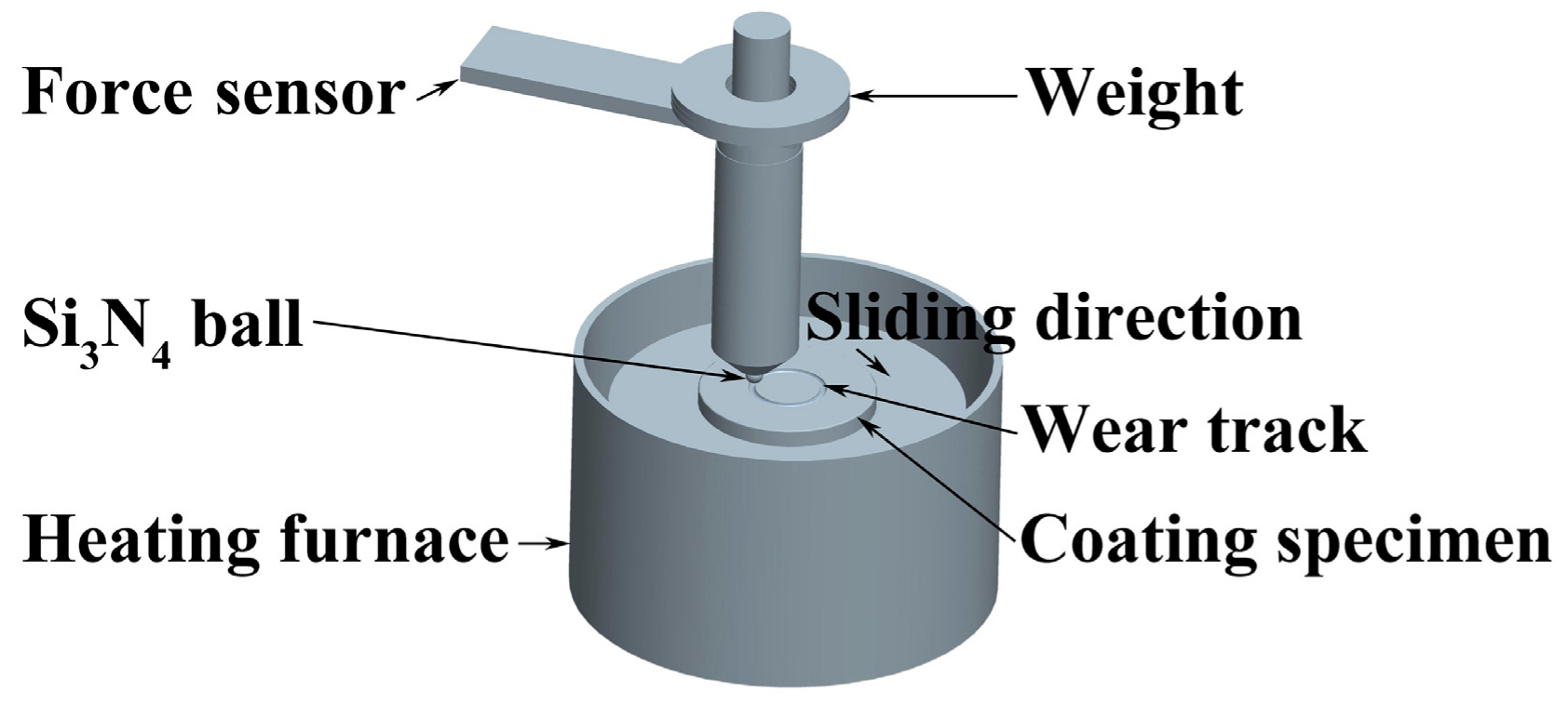
A high-temperature ball-on-disc friction and wear tester (HT-1000, Zhongke Kaihua Science and Technology Development Ltd., Lanzhou, China) was used to investigate the wear resistance of the coating. Figure 1 shows the schematic diagram of the wear test. Si3N4 balls with a diameter of Φ 5 mm were fixed on a loading rod. The coating specimen was fixed on a specimen pan by screws. They can contact with each other with the help of the weight with a load of 5 N. During the test, friction force was continuously measured by a force sensor, and then divided by the normal load to calculate the friction coefficient.
Before testing, the coating was polished to reach a roughness of about Ra = 0.7 μm. When the load was added, the heating furnace was heated up to test temperatures with a heating speed of 10 °C·min−1 in atmospheric environment. The coating specimen rotated at a set velocity of 573 r·min−1 with a friction radius of 5 mm. The coating specimen was taken out when the wear time reached 20 min. A three-dimensional (3D) confocal laser scanning microscope (LEXT OLS4000, OLYMPUS, Tokyo, Japan) was used to measure the cross-sectional area of the wear tracks A (mm2). The volume wear rate W (mm3·N−1·m−1) was calculated according to W = A·P/(S·L), in which P is perimeter of the wear track in mm, S is sliding distance in m, and L is the load in N. For each wear temperature, three specimens were tested and the volume wear rate result was reported as an average value. More details about the wear test were described in previous publications [14,21].
3. Results and Discussion
3.1. Microstructure of Feedstock and HEA/Ni60 Coating
Figure 2a shows the surface morphology of the mechanically blended HEA/Ni60 powder. It can be observed that the atomized Ni60 particles were spherical in shape with a smooth surface, while the ball-milled AlCoCrFeNiTi particles were near-equiaxed in shape with a rough surface. At a higher magnification (Figure 2b), gaps can be observed on the surface of the AlCoCrFeNiTi particle, and small particles adhered to it. These characteristics were caused by the particles which were not well cold-welded during the ball milling process. Due to its appropriate particle size and shape, the mixed powder exhibited good flowability and was suitable for plasma spraying.
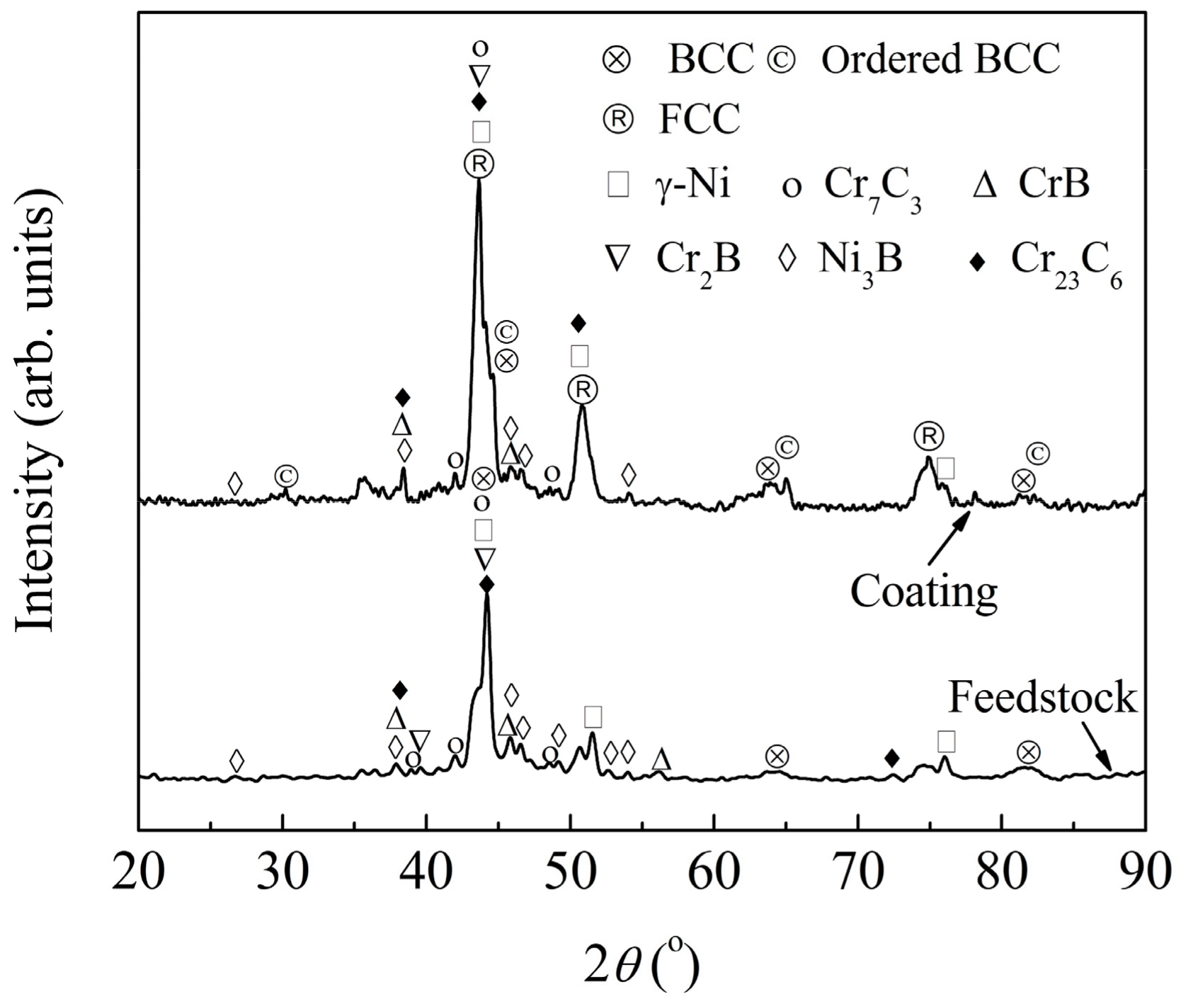
Figure 3 provides the XRD patterns of the mechanically blended HEA/Ni60 powder and the coating. From the pattern of the feedstock, phases such as γ-Ni, Cr7C3, CrB, Cr2B, Ni3B, and Cr23C6 present in the atomized Ni60 powder were detected. Additionally, diffraction peaks of typical body-centered cubic (BCC) phase at 44.6°, 65.0°, and 82.3° were detected, which were obviously broadened because of the grain refinement and increase of the lattice strain of the ball milled HEA powder during ball milling.
As shown in Figure 3, in the plasma-sprayed coating, the peak intensity of the matrix BCC phase decreased, and new phases, such as face-centered cubic (FCC) and minor ordered BCC phases were found. This can resulted from the formation of the stable equilibrium phases from the metastable supersaturated solid solution present in the ball milled HEA feedstock [4]. Moreover, compared with that of the feedstock, a slight shift to the left of the major diffraction peak can be observed in Figure 3, which was due to the difference of crystallinity level and lattice strain between the feedstock and the coating [22]. Furthermore, no obvious phase transformation of Ni60 occurred after plasma spraying.
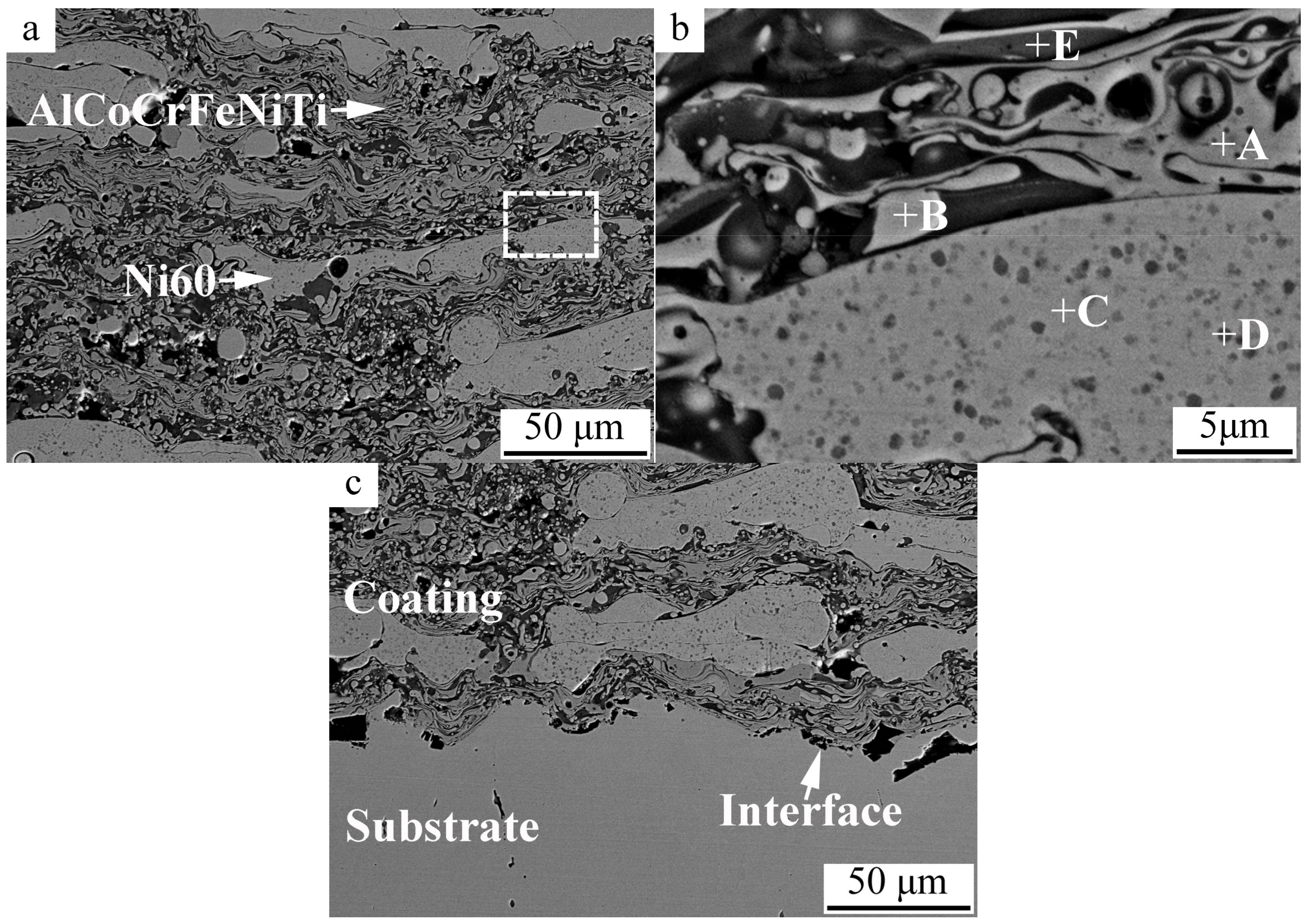
Figure 4 provides cross-sectional microstructure of the HEA/Ni60 coating. From Figure 4a, a typical lamellar structure of a plasma-sprayed coating containing major molten flattened splats and minor unmelted particles can be observed. Ni60 splats with a thickness of less than 40 μm were distributed uniformly in the AlCoCrFeNiTi matrix. Very few pores present in the coating with a size of less than 20 μm. It was reported that these pores are caused by imperfect wetting and inadequate filling of the melting droplets to the previously formed rough splat surfaces [23,24,25,26]. Apart from these pores, the coating was compact.
EDS analysis was conducted on points with typical contrasts on the coating cross-section in Figure 4b. The chemical composition is listed in Table 2. Point A, which was rich in Co, Cr, Fe, and Ni, was related to the BCC and ordered BCC phases (Figure 3) presented in the AlCoCrFeNiTi high-entropy alloy splats. Point B was rich in Co and Ni, but not Al, and it was related to the FCC phase in the HEA splat detected by XRD. According to the previous reports [27,28], Cr and Ni are promoters of BCC and FCC phases, respectively. It was also reported that BCC and ordered BCC phases which were rich in Fe-Cr and Al-Ni were found by EDS in vacuum induction melting AlCoCrFeNiTi0.5 HEAs [29]. In the Ni60 splats, the matrix (e.g., point C) with a light gray contrast and a large amount of Ni and Cr was identified to be the γ-Ni solid solution phase detected by XRD (Figure 3). The cellular eutectic precipitations with a dark gray contrast (e.g., point D) scattered in the matrix could be the reinforcements (such as CrB, Cr2B, and Ni3B phases) due to its high content of B. Additionally, a few points (e.g., point E) with a dark gray contrast and higher oxygen content were caused by the oxidation of HEA powder owing to the air permeation into the plasma jet [30]. Usually, during plasma spraying, because of the operating atmosphere, oxidation of the metallic elements cannot be avoided [31]. However, diffraction peaks of these oxides were not detected in Figure 3 due to their lower contents.
Figure 4c shows the coating/substrate interface at a higher magnification. It is noted that the surface profile of the substrate in the HEA/Ni60 coating is much rougher than that in the HEA coating [14]. Thus, during spraying, as the high-temperature droplets impact on the substrate surface, and then spread along the rough surface, strong mechanical bonding can be formed due to the cooling, solidification and shrinkage of the splats. In addition, the addition of large Ni60 particles played an important role in strengthening the coating. First, Ni60 with a lower melting point can completely wet along the previously formed rough surface and sufficiently fill in the holes, which resulted in a strong bonding between the Ni60 particles and the nether splats. Second, since Ni60 is present in the coating as large particles, they can increase the surface roughness of the formed coating after their deposition. Therefore, strong mechanical bonding can be formed between the subsequent splats and the previously formed Ni60 particles. Thus, good contact between Ni60 particles and AlCoCrFeNiTi splats was formed (as shown in Figure 4c), which can cause a higher cohesion strength of the coating. Indeed, tensile test results showed that fracture of the specimen mainly occurred in the E-7 adhesive layer (Figure 5) and the average tensile strength was 60.1 MPa. Therefore, bonding strength of this coating was above 60.1 MPa, which is far higher than that of the HEA coating (50.3 MPa) in the previous study [14].
3.2. Microhardness of HEA/Ni60 Coating
Microhardness of the HEA/Ni60 coating is shown in Figure 6, and that of the HEA coating in our previous study [14] are also given out for comparison. As shown in Figure 6, microhardness of the HEA/Ni60 coating increased significantly from the substrate to the substrate/coating interface, and then to the coating. For example, at the distance of −100 μm, the substrate microhardness was 183 HV, while at the distance of −50 μm, it increased to 289 HV. A value of 443 HV was obtained at the substrate/coating interface. The coating microhardness was 636 HV, 665 HV, and 727 HV at the distance of 50 μm, 100 μm, and 150 μm, respectively. At the distance of 200 μm (near the coating surface), a lower value of 639 HV was obtained.
For both the HEA/Ni60 and HEA coatings, a similar microhardness was obtained at distances of −100 μm and −50 μm. This can be attributed to the same sand blasting parameters. During sand blasting, work hardening took place [31], and this can increase the substrate hardness significantly to a value of nearly 300 HV, e.g., at the distance of −50 μm. However, at a deeper distance (e.g., −100 μm), the substrate hardness was not affected significantly, and it was close to that of 316 stainless steel prior to spraying (173 HV). At the substrate/coating interface, the hardness in this study was much higher than that of the HEA coating (396 HV). It can be attributed to the better mechanical bonding in Figure 4c, which also caused a higher bonding strength.
An average microhardness of 676 HV was obtained for the main body of the coating, which is far higher than that of the HEA coating in the previous work (642 HV) [14]. The main reason can be the addition of the reinforcement, Ni60. As discussed in Section 3.1, after spraying, γ-Ni, Cr7C3, CrB, Cr2B, and Cr23C6 phases were detected in the coating. For the γ-Ni solid solution, solution hardening can strength the Ni60 splat significantly. Moreover, it was reported that for Ni60, the addition of Cr element can improve its hardness by formation of carbides and borides with high hardness, and the addition of B element can enhance the formation of the hard phases [19]. Thus, the dispersion strengthening of the hard interstitial compounds such as Cr7C3, CrB, Cr2B, and Cr23C6 can also strength the Ni60 splat. Both the solution hardening and dispersion strengthening increased the hardness of Ni60, and then the HEA/Ni60 coating. Furthermore, porosity has significant effect on the hardness of thermally-sprayed coatings [31]. As shown in Figure 4a, the addition of the large Ni60 particles with a low melting point can completely wet along the previously surface and fill in the holes, and finally result in a good bonding between the molten Ni60 and AlCoCrFeNiTi splats, and a compact coating was obtained. Hence, the low porosity of the coating in the present study can be another important reason of the high hardness. At the distance of 200 μm, the coating hardness decreased to a lower value. This can be resulted from the edge effect of thermally-sprayed coatings. During spraying, lower effect of sintering induced by few subsequent particles can increase the porosity of the coating [32], which can decrease the coating hardness.
3.3. Wear Resistance of HEA/Ni60 Coating
3.3.1. Wear Mechanism
To investigate the wear mechanism of the HEA/Ni60 coating, morphology of the worn surfaces at 25 °C and 500 °C was analyzed.
Figure 7a,c show the morphology of worn surface of the coating and the counterpart at 25 °C. From Figure 7a, an average width of about 0.76 mm for the wear track was obtained. The worn surface of the coating was quite rough with large numbers of delamination and lips present on it (Figure 7a,b), and lots of fine flakes with a dimension of less than 10 μm along the sliding direction can be observed on the counterpart surface (Figure 7c). These facts illustrate that adhesive wear took place during the wear experiment. During testing, welding between the coating and the counterpart occurred due to their direct contact under the load applied. As the ball slid on the coating, splats on the surface of the coating can adhere to the ball, and then be dragged out, which results in delamination. Peeling of the splats was caused by the limited interlamellar bonding ratio. In thermally-sprayed coatings, the bonding ratio between flattened splats was investigated, and a result of less than one third was obtained [31]. Consequently, the peelings can be pushed to other areas of the worn surface along the sliding direction, and the lips formed. Repeated adhesion and shear deformation accelerated the formation of lips and flakes. EDS analysis result showed that the lips (e.g., point 1 in Figure 7b) were oxidized with an oxygen content of up to 64.57 at % (Table 3). It was reported that due to the friction heating, flash temperature on the up-most sliding surface (e.g., lips) would increase [33], which caused the oxidation of the lips. The solid solution matrix of BCC, ordered BCC, FCC, and γ-Ni with excellent plasticity and toughness prevented the moving of the lips, which can further enhance the coating wear resistance. In addition, lots of furrows with a width of about 10 μm can be observed on the worn surface in Figure 7b, which illustrates that abrasive wear was another wear mechanism. During wear testing, the hard oxidized lips can be crushed, and fine oxide particles formed. Under the load applied, these fine oxide particles play the part of ploughs and the furrows along the sliding direction were formed. It is worth noting that on the surface of Ni60 (e.g., point 2 in Figure 7b), which was identified by EDS (Table 3), no obvious furrows can be seen. This can be explained by the high hardness of Ni60 at 25 °C, which is much higher than that of AlCoCrFeNiTi [14]. The characteristics of delamination, lips, and furrows cause a higher roughness of the worn surface.
Compared with that at 25 °C, the morphology of worn surface of the coating and the counterpart changed significantly at 500 °C (Figure 7d–f). With increasing the wear temperature from 25 to 500 °C, the wear track became narrower (Figure 7d), with an average width of about 0.59 mm. A smoother wear surface was obtained and no obvious delamination and lips are observed. At the edge of the wear track (Figure 7d), obvious plastic deformation can be observed. Additionally, the flakes adhering to the counterpart became a thin slice with a dimension from several micrometers to tens of micrometers (Figure 7f). As the temperature increased to 500 °C, the coating hardness decreased, while the plasticity increased. During testing, as the ball slid on the coating surface, plastic deformation of the metallic splats occurred with the load applied. Thus, the interlamellar gaps can be healed and good bonding between the splats formed, and delamination cannot occur and lips cannot form. Thus, a smoother wear surface was obtained. Due to the low hardness and good plasticity, plastic deformation occurred on the edge of the wear track. Moreover, finer furrows with a width of about 5 μm can be found in Figure 7e, which illustrates that abrasive wear took place. According to the EDS analysis results listed in Table 3, the coating surface (e.g., point 4) was slightly oxidized. Oxidation of the coating was attributed to the flash temperature during wear test and the defects existed in the coating (e.g., interlamellar gaps and pores), which is a typical problem for the plasma-sprayed metallic coatings. During high temperature wear, crushing of the tribo film on the worn surface took place, which resulted in the formation of fine particles with small sizes. Under the load applied, these fine particles play the part of ploughs and the furrows along the sliding direction were formed (Figure 7d,e). From Table 3, it can be found that point 3 was related to Ni60, which was not oxidized due to its oxidation resistance at 500 °C. However, furrows can also be observed on the surface of Ni60 particles. This could be owing to the decrease of its hardness. The coating material from the furrows was aggregated, extruded, and adhered to the surface of the counterpart as flakes with thin slice shapes because of its good plasticity at 500 °C.
3.3.2. Friction Coefficient
Figure 8 provides the friction coefficient of HEA/Ni60 coating as a function of wear time. From the wear curves, two obvious stages (running-in and steady wear stages) can be observed. For the curve at 25 °C, the friction coefficient increased within 5 min at the running-in stage. In the steady wear stage, the average friction coefficient is much higher with a larger fluctuation (0.80 ± 0.03), which can be attributed to the changing of the roughness from a polished smooth surface (with a roughness of about Ra = 0.7 μm) to a rough worn surface (Figure 7a,b). At high temperature, the friction coefficient curves showed short time running-in stages, which can be caused by the welding of two contact surfaces at high temperatures. At 500 °C, the average friction coefficient in the steady wear stage became lower with small fluctuation (0.57 ± 0.03), which was caused by the smooth, worn surfaces in Figure 7d,e.
3.3.3. Volume Wear Rate
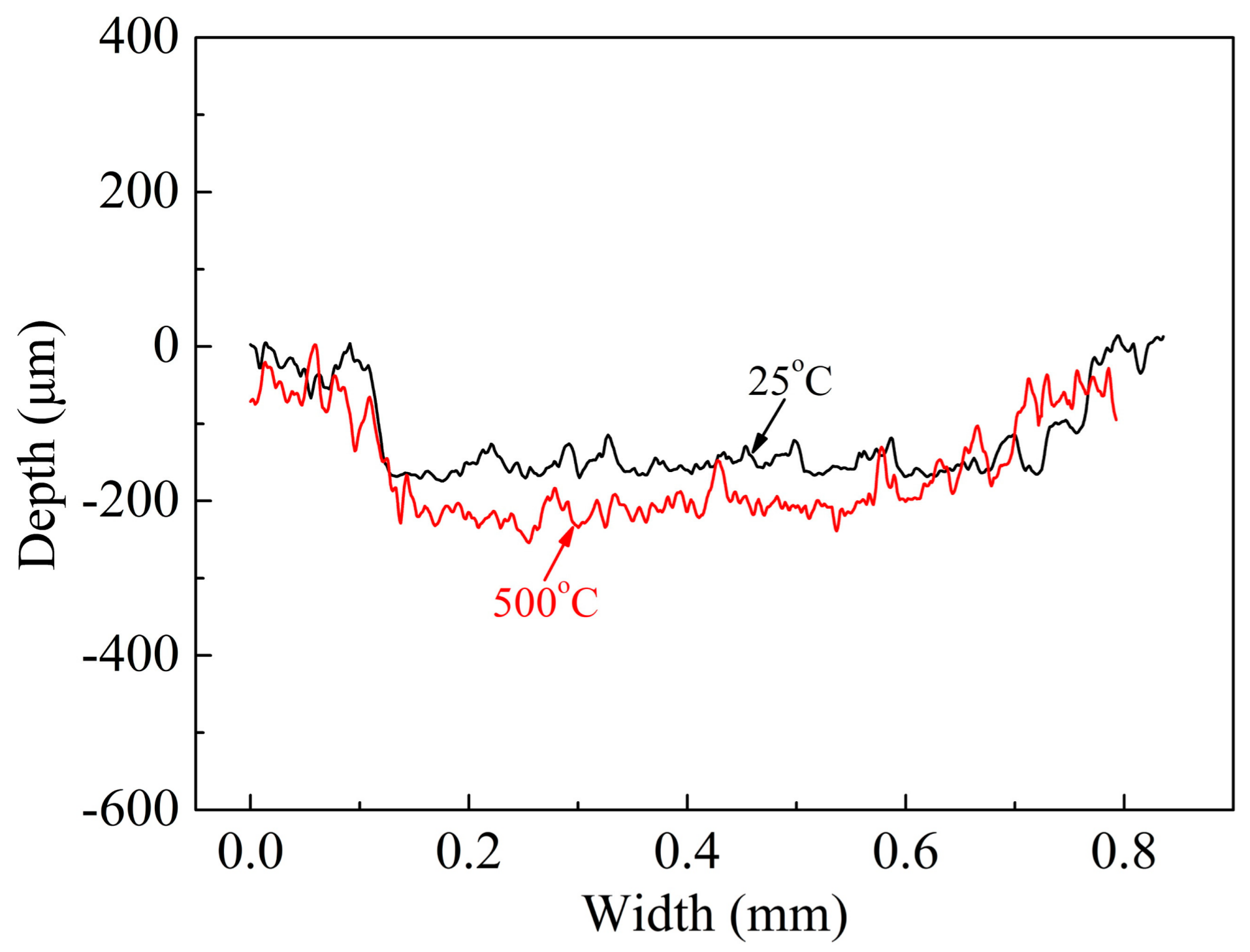
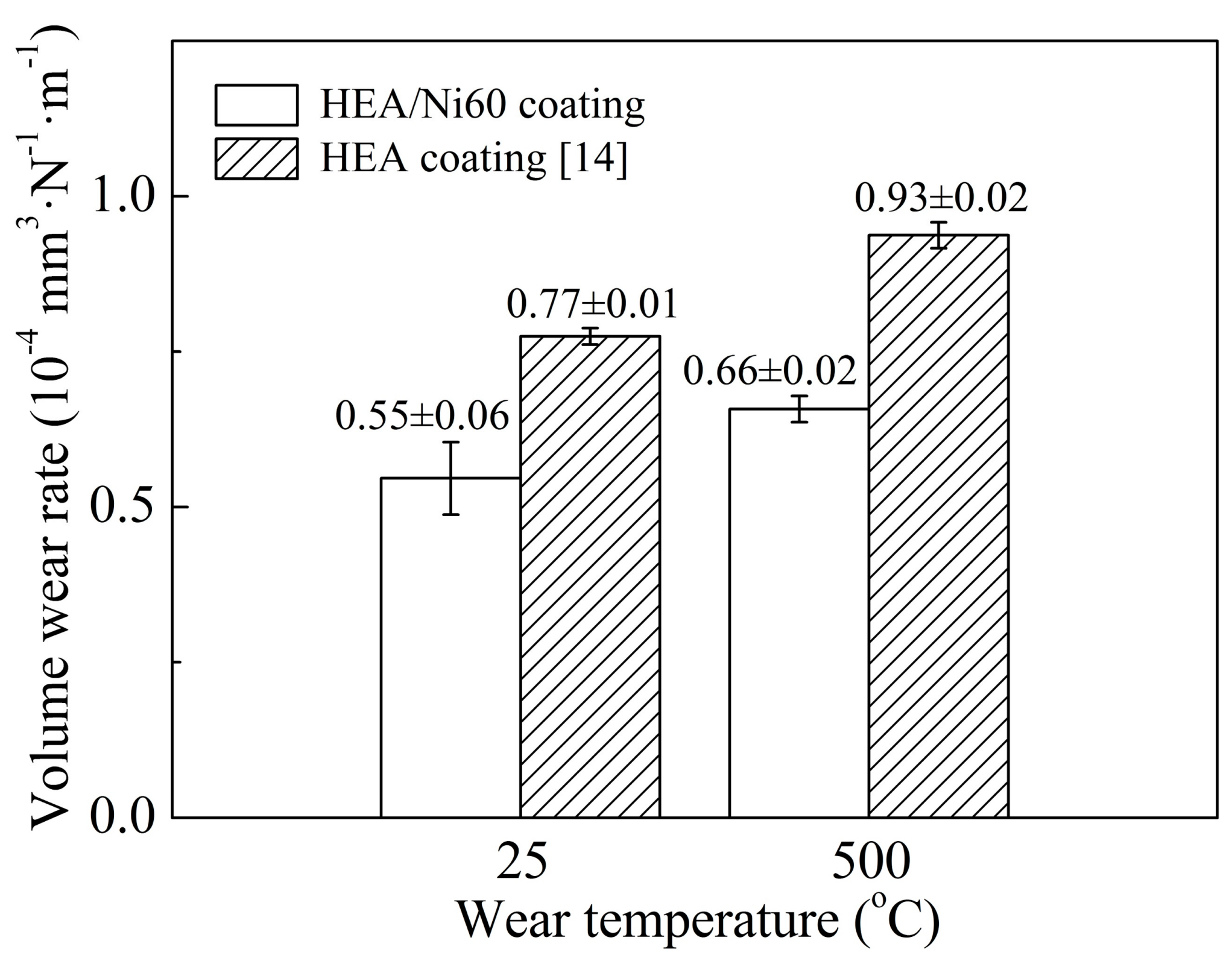
Three-dimensional non-contact surface mapping across the wear tracks of HEA/Ni60 coating at 25 °C and 500 °C is shown in Figure 9. Figure 10 provides the volume wear rates of the HEA/Ni60 and HEA coatings as a function of test temperature. With increasing the wear temperature from 25 to 500 °C, the volume wear rates of the coating increased. For example, volume wear rates of the coating at 25 °C and 500 °C were 0.55 ± 0.06 × 10⁻⁴ mm3·N−1·m−1 and 0.66 ± 0.02 × 10⁻⁴ mm3·N−1·m−1, respectively. This could be owing to the decrease of the coating hardness. Wear resistance of this coating was better than that of the HEA coating and also the 316 stainless steel substrate material, which can result from the addition of the hard Ni60. Therefore, Ni60 is an appropriate reinforcement to further enhance the wear resistance of HEA coating.
4. Conclusions
A compact AlCoCrFeNiTi/Ni60 coating with Ni60 splats uniformly distributed in AlCoCrFeNiTi matrix was deposited by plasma spraying. After spraying, matrix BCC, FCC, and ordered BCC phases were detected in the coating.
The added large Ni60 particles played an important role in strengthening the coating. A strong mechanical bonding between Ni60 and AlCoCrFeNiTi splats caused a higher cohesion strength. Tensile test results showed that bonding strength of this coating was above 60.1 MPa, which is far higher than that of the AlCoCrFeNiTi coating in the previous study.
An average microhardness of 676 HV was obtained for the main body of the coating, which is far higher than that of the HEA coating in the previous work. The main reason can be attributed to the addition of the reinforcement, Ni60. Solution hardening in γ-Ni and dispersion strengthening of the hard interstitial compounds, such as Cr7C3, CrB, Cr2B, and Cr23C6 increased the hardness of Ni60, and then the HEA/Ni60 coating.
During wear testing at 25 °C, adhesive wear and abrasive wear occurred, while at 500 °C, abrasive wear took place. Volume wear rates of the coating at 25 °C and 500 °C were 0.55 ± 0.06 × 10⁻⁴ mm3·N−1·m−1 and 0.66 ± 0.02 × 10⁻⁴ mm3·N−1·m−1, respectively. Wear resistance of this coating was better than that of the HEA coating, which can result from the addition of the hard Ni60. Therefore, Ni60 is an appropriate reinforcement to further enhance the wear resistance of HEA coating.
Acknowledgments
This work was supported by the National Natural Science Foundation of China (grant number 51401091); a project funded by the Priority Academic Program Development of Jiangsu Higher Education Institutions (PAPD); and a Top-notch Academic Programs Project of Jiangsu Higher Education Institutions (TAPP).
Author Contributions
Lihui Tian and Wei Xiong conceived and designed the experiments; Lihui Tian, Zongkang Feng, and Wei Xiong performed the experiments and analyzed the data; and Lihui Tian wrote the paper.
Conflicts of Interest
The authors declare no conflict of interest.
References
- Cantor, B.; Chang, I.T.H.; Knight, P.; Vincent, A.J.B. Microstructural development in equiatomic multicomponent alloys. Mater. Sci. Eng. A 2004, 375, 213–218. [Google Scholar] [CrossRef]
- Chen, Y.Y.; Duval, T.; Hung, U.D.; Yeh, J.W.; Shih, H.C. Microstructure and electrochemical properties of high entropy alloys—A comparison with type-304 stainless steel. Corros. Sci. 2005, 47, 2257–2279. [Google Scholar] [CrossRef]
- Niu, S.Z.; Kou, H.C.; Guo, T.; Zhang, Y.; Wang, J.; Li, J.S. Strengthening of nanoprecipitations in an annealed Al0.5CoCrFeNi high entropy alloy. Mater. Sci. Eng. A 2016, 671, 82–86. [Google Scholar] [CrossRef]
- Zhang, K.B.; Fu, Z.Y.; Zhang, J.Y.; Wang, W.M.; Lee, S.W.; Niihara, K. Characterization of nanocrystalline CoCrFeNiTiAl high-entropy solid solution processed by mechanical alloying. J. Alloys Compd. 2010, 495, 33–38. [Google Scholar] [CrossRef]
- Peng, Z.; Liu, N.; Zhang, S.Y.; Wu, P.H.; Wang, X.J. Liquid-phase separation of immiscible CrCuxFeMoyNi high-entropy alloys. Mater. Sci. Technol. 2017, 33, 1352–1359. [Google Scholar] [CrossRef]
- Wu, P.H.; Peng, Z.; Liu, N.; Niu, M.Y.; Zhu, Z.X.; Wang, X.J. The effect of Mn content on the microstructure and properties of CoCrCu0.1Fe0.15Mo1.5MnxNi near equiatomic alloys. Mater. Trans. JIM 2016, 57, 5–8. [Google Scholar] [CrossRef]
- Soare, V.; Burada, M.; Constantin, I.; Mitrică, D.; Bădiliţă, V.; Caragea, A.; Târcolea, M. Electrochemical deposition and microstructural characterization of AlCrFeMnNi and AlCrCuFeMnNi high entropy alloy thin films. Appl. Surf. Sci. 2015, 358, 533–539. [Google Scholar] [CrossRef]
- Braeckman, B.R.; Boydens, F.; Hidalgo, H.; Dutheil, P.; Jullien, M.; Thomann, A.L.; Depla, D. High entropy alloy thin films deposited by magnetron sputtering of powder targets. Thin Solid Films 2015, 580, 71–76. [Google Scholar] [CrossRef]
- Xu, J.H.; Chen, J.; Yu, L.H. Influence of Si content on the microstructure and mechanical properties of VSiN films deposited by reactive magnetron sputtering. Vacuum 2016, 131, 51–57. [Google Scholar] [CrossRef]
- Zhang, H.; Pan, Y.; He, Y.Z.; Jiao, H.S. Microstructure and properties of 6FeNiCoSiCrAlTi high-entropy alloy coating prepared by laser cladding. Appl. Surf. Sci. 2011, 257, 2259–2263. [Google Scholar] [CrossRef]
- Jin, Y.J.; Li, R.F.; Zheng, Q.C.; Li, H.; Wu, M.F. Structure and properties of laser-cladded Ni-based amorphous composite coatings. Mater. Sci. Technol. 2016, 32, 1206–1211. [Google Scholar] [CrossRef]
- Ang, A.S.M.; Berndt, C.C.; Sesso, M.L.; Anupam, A.; Praveen, S.; Kottada, R.S.; Murty, B.S. Plasma-sprayed high entropy alloys: Microstructure and properties of AlCoCrFeNi and MnCoCrFeNi. Metall. Mater. Trans. A 2015, 46, 791–800. [Google Scholar] [CrossRef]
- Wang, L.M.; Chen, C.C.; Yeh, J.W.; Ke, S.T. The microstructure and strengthening mechanism of thermal spray coating NixCo0.6Fe0.2CrySizAlTi0.2 high-entropy alloys. Mater. Chem. Phys. 2011, 126, 880–885. [Google Scholar] [CrossRef]
- Tian, L.H.; Xiong, W.; Liu, C.; Lu, S.; Fu, M. Microstructure and wear behavior of atmospheric plasma-sprayed AlCoCrFeNiTi high-entropy alloy coating. J. Mater. Eng. Perform. 2016, 25, 5513–5521. [Google Scholar] [CrossRef]
- Oñoro, J. High-temperature mechanical properties of aluminium alloys reinforced with titanium diboride (TiB2) particles. Rare Met. 2011, 499, 421–426. [Google Scholar] [CrossRef] [Green Version]
- Shao, J.Z.; Li, J.; Song, R.; Bai, L.L.; Chen, J.L.; Qu, C.C. Microstructure and wear behaviors of TiB/TiC reinforced Ti2Ni/α(Ti) matrix coating produced by laser cladding. Rare Met. 2016. [Google Scholar] [CrossRef]
- Simunovic, K.; Saric, T.; Simunovic, G. Different approaches to the investigation and testing of the Ni-based self-fluxing alloy coatings—A review. Part 1: General facts, wear and corrosion investigations. Tribol. Trans. 2014, 57, 955–979. [Google Scholar] [CrossRef]
- Simunovic, K.; Saric, T.; Simunovic, G. Different approaches to the investigation and testing of the Ni-based self-fluxing alloy coatings—A review. Part 2: Microstructure, adhesive strength, cracking behavior, and residual stresses investigations. Tribol. Trans. 2014, 57, 980–1000. [Google Scholar] [CrossRef]
- Natarajan, S.; Anand, E.E.; Akhilesh, K.S.; Rajagopal, A.; Nambiar, P.P. Effect of graphite addition on the microstructure, hardness and abrasive wear behavior of plasma sprayed NiCrBSi coatings. Mater. Chem. Phys. 2016, 175, 100–106. [Google Scholar] [CrossRef]
- ISO 14916 Thermal Spraying–Determination of Tensile Adhesive Strength; ISO: Geneva, Switzerland, 1999.
- Tian, L.H.; Fu, M.; Xiong, W. Microstructural evolution of AlCoCrFeNiSi high-entropy alloy powder during mechanical alloying and its coating performance. Materials 2018, 11, 320. [Google Scholar] [CrossRef] [PubMed]
- Houdková, Š.; Smazalová, E.; Vostřák, M.; Schubert, J. Properties of NiCrBSi coating, as sprayed and remelted by different technologies. Surf. Coat. Technol. 2014, 253, 14–26. [Google Scholar] [CrossRef]
- McPherson, R. The relationship between the mechanism of formation, microstructure and properties of plasma-sprayed coatings. Thin Solid Films 1981, 83, 297–310. [Google Scholar] [CrossRef]
- Li, C.J.; Ohmori, A.; McPherson, R. The relationship between microstructure and Young’s modulus of thermally sprayed ceramic coatings. J. Mater. Sci. 1997, 32, 997–1004. [Google Scholar] [CrossRef]
- Li, C.J.; Ohmori, A. Relationships between the microstructure and properties of thermally sprayed deposits. J. Therm. Spray Technol. 2002, 11, 365–374. [Google Scholar] [CrossRef]
- Xing, Y.Z.; Li, C.J.; Li, C.X.; Yang, G.J. Influence of through-lamella grain growth on ionic conductivity of plasma-sprayed yttria-stabilized zirconia as an electrolyte in solid oxide fuel cells. J. Power Sources 2008, 176, 31–38. [Google Scholar] [CrossRef]
- Tung, C.C.; Yeh, J.W.; Shun, T.T.; Chen, S.K.; Huang, Y.S.; Chen, H.C. On the elemental effect of AlCoCrCuFeNi high-entropy alloy system. Mater. Lett. 2007, 61, 1–5. [Google Scholar] [CrossRef]
- Lin, C.W.; Tsai, M.H.; Tsai, C.W.; Yeh, J.W.; Chen, S.K. Microstructure and aging behaviour of Al5Cr32Fe35Ni22Ti6 high entropy alloy. Mater. Sci. Technol. 2015, 31, 1165–1170. [Google Scholar] [CrossRef]
- Yu, Y.; Liu, W.M.; Zhang, T.B.; Li, J.S.; Wang, J.; Kou, H.C.; Li, J. Microstructure and tribological properties of AlCoCrFeNiTi0.5 high-entropy alloy in hydrogen peroxide solution. Metall. Mater. Trans. A 2014, 45, 201–207. [Google Scholar] [CrossRef]
- Leitner, J.; Dubsky, J.; Had, J.; Hanousek, F.; Kolman, B.; Volenik, K. Metastable chromium-rich oxide formed during plasma spraying of high-alloy steel. Oxid. Met. 2000, 54, 549–558. [Google Scholar] [CrossRef]
- Pawlowski, L. The Science and Engineering of Thermal Spray Coatings, 2nd ed.; John Wiley & Sons: New York, NY, USA, 2008. [Google Scholar]
- Li, J.F.; Ding, C.X. Study on Vickers hardness of plasma sprayed Cr3C2-NiCr coating. J. Chin. Ceram. Soc. 2000, 28, 223–228. [Google Scholar]
- Luo, Q. Temperature dependent friction and wear of magnetron sputtered coating TiAlN/VN. Wear 2011, 271, 2058–2066. [Google Scholar] [CrossRef]
Figure 1.
Schematic diagram of wear test.

Figure 2.
Surface morphology of feedstock: (a) mechanically blended HEA/Ni60 powder and (b) HEA powder at a higher magnification.
Figure 2.
Surface morphology of feedstock: (a) mechanically blended HEA/Ni60 powder and (b) HEA powder at a higher magnification.
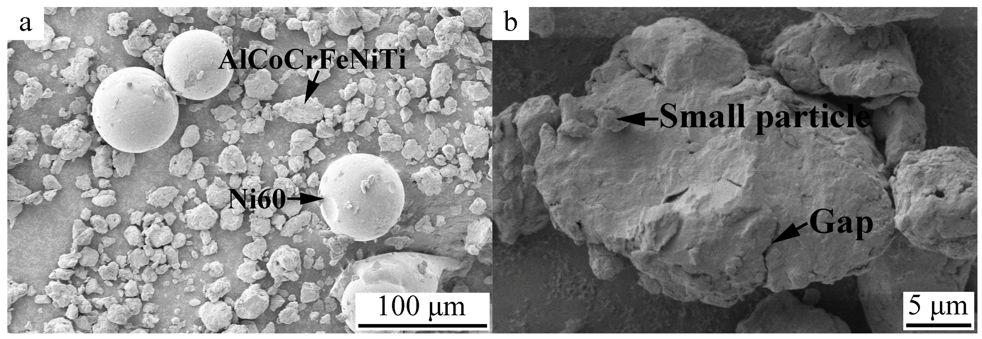
Figure 3.
X-ray diffraction (XRD) patterns of feedstock and HEA/Ni60 coating.

Figure 4.
Cross-sectional microstructure of HEA/Ni60 coating (a,b) and coating/substrate interface (c).
Figure 4.
Cross-sectional microstructure of HEA/Ni60 coating (a,b) and coating/substrate interface (c).

Figure 5.
Fracture of tensile test specimen.
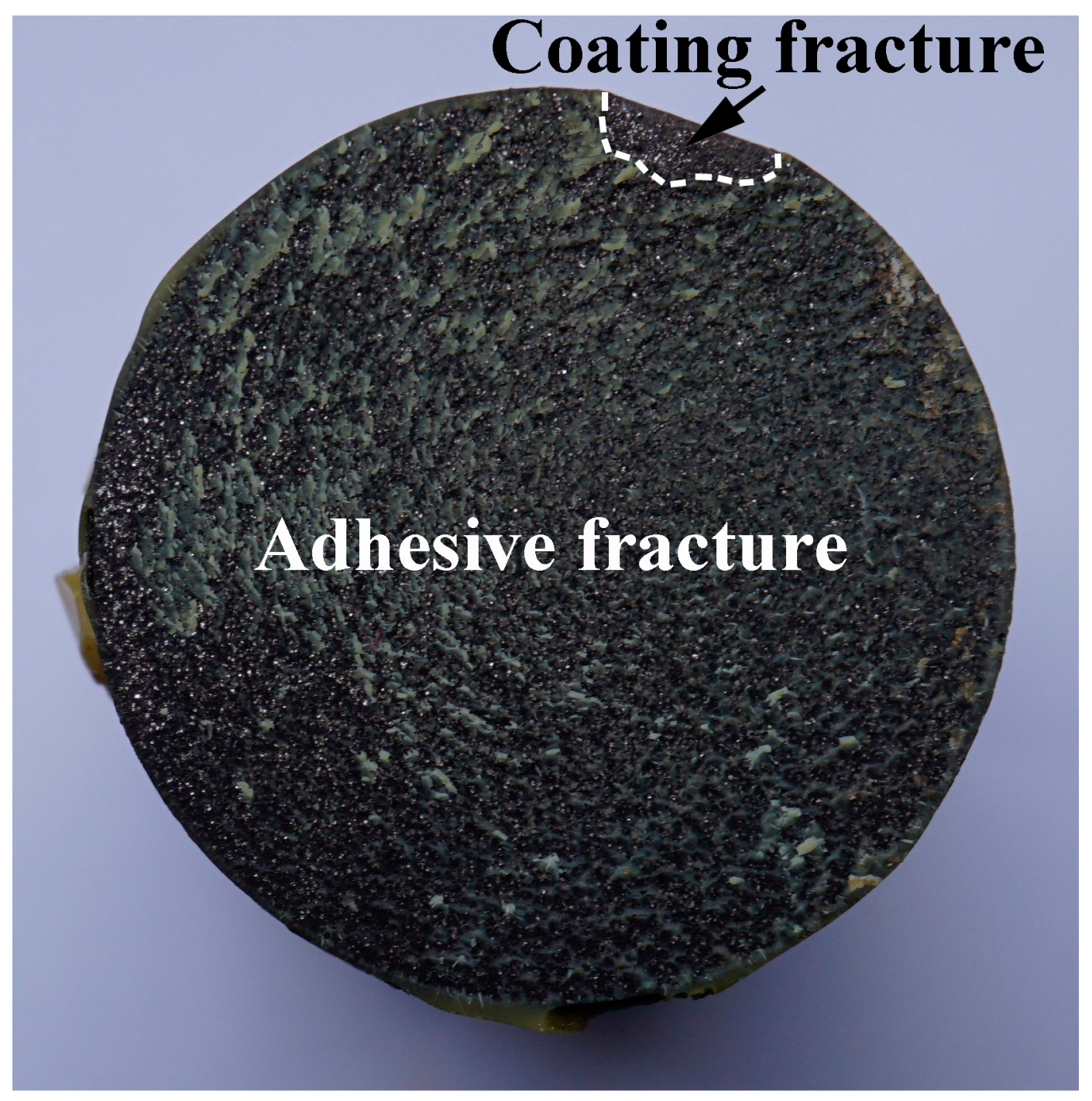
Figure 6.
Microhardness of HEA/Ni60 coating.
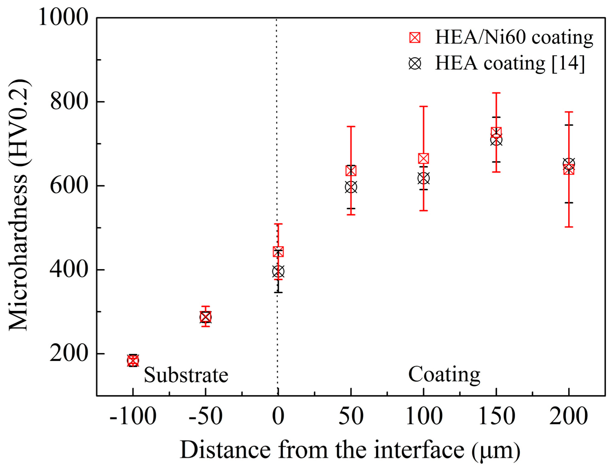
Figure 7.
Worn surfaces of HEA/Ni60 coating and counterpart at 25 °C (a–c) and 500 °C (d–f).
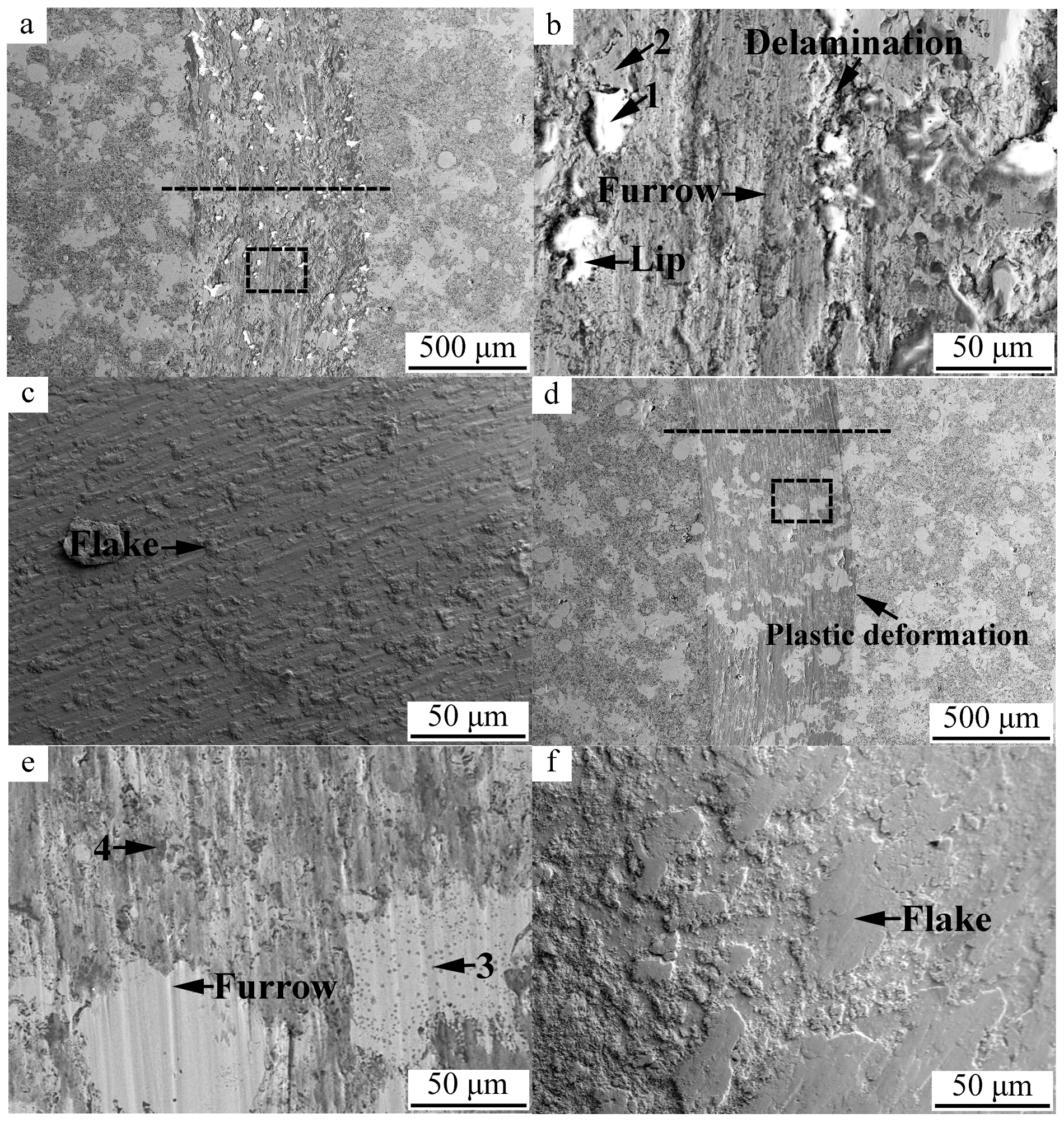
Figure 8.
Friction coefficients of HEA/Ni60 coating at 25 °C and 500 °C.
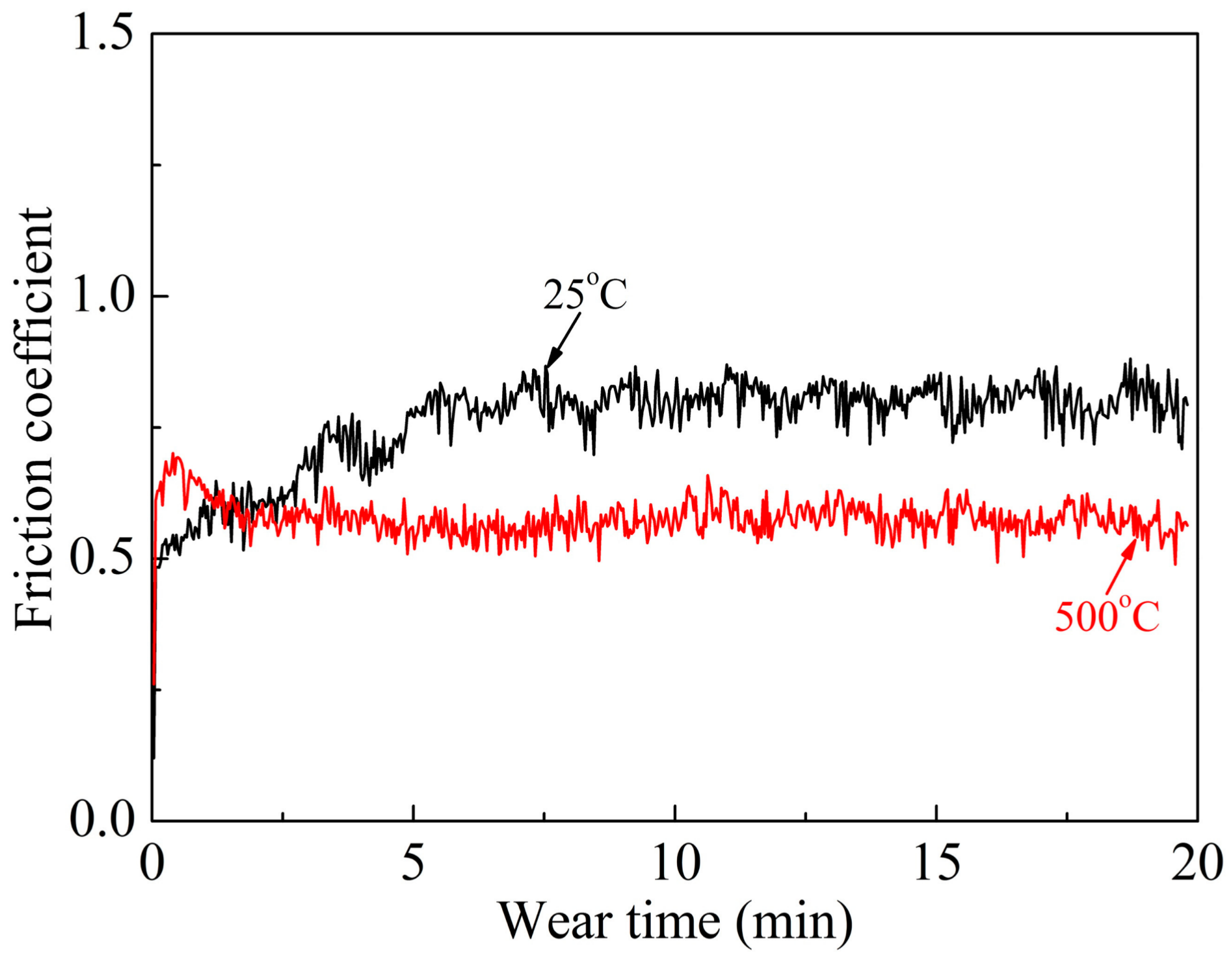
Figure 9.
Three-dimensional (3D) non-contact surface mapping across the wear tracks of HEA/Ni60 coating at 25 °C and 500 °C in Figure 7a,d.
Figure 9.
Three-dimensional (3D) non-contact surface mapping across the wear tracks of HEA/Ni60 coating at 25 °C and 500 °C in Figure 7a,d.

Figure 10.
Volume wear rates of HEA/Ni60 coating at 25 °C and 500 °C.


Table 1.
Chemical composition of Ni60 powder (wt %).
| Element | Content |
|---|---|
| C | 0.63 |
| B | 2.97 |
| Si | 4.50 |
| Fe | 5.31 |
| Cr | 16.20 |
| Ni | Bal. |
Table 2.
Energy dispersive spectroscopy (EDS) analysis results of typical points in Figure 4b (at %).
Table 2.
Energy dispersive spectroscopy (EDS) analysis results of typical points in Figure 4b (at %).
| Point | Al | Co | Cr | Fe | Ni | Ti | Si | O | C | B |
|---|---|---|---|---|---|---|---|---|---|---|
| A | 8.66 | 21.65 | 17.72 | 20.16 | 20.98 | 10.83 | 0.00 | 0.00 | 0.00 | 0.00 |
| B | 0.00 | 33.09 | 1.29 | 5.12 | 53.95 | 0.94 | 0.00 | 5.61 | 0.00 | 0.00 |
| C | 0.00 | 0.00 | 39.75 | 4.94 | 49.47 | 0.00 | 5.32 | 0.00 | 0.52 | 0.00 |
| D | 0.00 | 0.00 | 29.21 | 8.44 | 25.76 | 0.00 | 4.49 | 0.00 | 0.00 | 32.10 |
| E | 6.28 | 7.24 | 1.94 | 18.42 | 7.77 | 4.42 | 0.00 | 53.93 | 0.00 | 0.00 |
Table 3.
Energy dispersive spectroscopy analysis results of typical points in Figure 7 (at %).
Table 3.
Energy dispersive spectroscopy analysis results of typical points in Figure 7 (at %).
| Point | Al | Co | Cr | Fe | Ni | Ti | Si | O |
|---|---|---|---|---|---|---|---|---|
| 1 | 2.39 | 3.95 | 4.05 | 3.92 | 11.58 | 5.04 | 4.50 | 64.57 |
| 2 | 0.00 | 0.00 | 25.15 | 5.10 | 47.60 | 0.50 | 5.67 | 15.98 |
| 3 | 0.00 | 0.00 | 15.46 | 4.93 | 71.57 | 0.00 | 8.04 | 0.00 |
| 4 | 3.07 | 6.08 | 4.59 | 6.03 | 12.52 | 6.91 | 0.87 | 59.92 |
© 2018 by the authors. Licensee MDPI, Basel, Switzerland. This article is an open access article distributed under the terms and conditions of the Creative Commons Attribution (CC BY) license (http://creativecommons.org/licenses/by/4.0/).
Share and Cite
MDPI and ACS Style
Tian, L.; Feng, Z.; Xiong, W. Microstructure, Microhardness, and Wear Resistance of AlCoCrFeNiTi/Ni60 Coating by Plasma Spraying. Coatings 2018, 8, 112. https://doi.org/10.3390/coatings8030112
AMA Style
Tian L, Feng Z, Xiong W. Microstructure, Microhardness, and Wear Resistance of AlCoCrFeNiTi/Ni60 Coating by Plasma Spraying. Coatings. 2018; 8(3):112. https://doi.org/10.3390/coatings8030112
Chicago/Turabian StyleTian, Lihui, Zongkang Feng, and Wei Xiong. 2018. "Microstructure, Microhardness, and Wear Resistance of AlCoCrFeNiTi/Ni60 Coating by Plasma Spraying" Coatings 8, no. 3: 112. https://doi.org/10.3390/coatings8030112
Note that from the first issue of 2016, this journal uses article numbers instead of page numbers. See further details here.