Effects of Graphene-Oxide-Modified Coating on the Properties of Carbon-Fiber-Reinforced Polypropylene Composites


1
Center for Civil Aviation Composites, Donghua University, 2999 North Renmin Road, Shanghai 201620, China
2
Key Laboratory of Textile Science & Technology, Ministry of Education, College of Textiles, Donghua University, 2999 North Renmin Road, Shanghai 201620, China
*
Authors to whom correspondence should be addressed.
Coatings 2018, 8(4), 149; https://doi.org/10.3390/coatings8040149
Submission received: 27 March 2018
/
Revised: 16 April 2018
/
Accepted: 17 April 2018
/
Published: 19 April 2018
Abstract
:Graphene oxide (GO) modified with ferrites (GO@Fe3O4) were studied to determine their effect on the interfacial properties of continuous carbon-fiber-reinforced thermoplastic composites. The GO@Fe3O4 were introduced by mixing them directly in an acrylic-styrene (AS) sizing emulsion suitable for the making of continuous carbon-fiber-reinforced thermoplastics and towpregs. A magnetic field was then generated during the online sizing using coils in order to change the morphology of the coating on the fiber. The effect on the obtained sizing quality and final properties of continuous carbon-fiber-reinforced thermoplastic composites was then studied. The results showed that the topography of the sized fibers was modified, showing a kind of “drag” effect and more than a 32% increase was obtained for interlaminar shear strength.

1. Introduction
Composite materials especially carbon-fiber-reinforced polymer composites (CFRPs) have been increasingly used in the past decades due to their potential for significant weight saving [1]. Thermoset resins have been the most widely used polymer matrix for CFRPs [2,3], but the requirements of thermoplastic matrices have drawn growing attention in recent years [4]. Compared to thermosets, thermoplastics have many advantages, such as inherently higher toughness, recyclability, and unlimited shelf life [5]. It has been well established that the mechanical performance of carbon-fiber-reinforced thermoplastic composites (CFRTPs) depend heavily on the interface adhesion between carbon fibers and thermoplastic matrices [6,7,8]. Unfortunately, the surfaces of unmodified carbon fibers (CFs) are inert due to the lack of functional groups [9], leading to the weak interfacial interactions between CFs and polymer matrix. To overcome this issue, many technologies have been developed to modify the surface of carbon fibers, such as coating by sizing agents [10,11], plasma treatment [12], chemical grafting [13], oxidation using nitric acid [14], electrochemical oxidation [15], ozone treatment [16], and growth of carbon nanotube and other graphene based materials [17,18].
Among the above methods, the sizing method is preferred in industrial applications because it is suitable for continuous production at low cost. The sizing agents are of low molecular weight or fully developed polymers that are applied directly to the carbon fiber surface to enhance matrix polymer adhesion and to reduce fiber damage during fiber processing. The use of nano-reinforcement in the sizing agent has been proven to be an effective method to further enhance the interfacial properties of CFRPs [19]. Liu et al. fabricated multiscale CFRTPs by directly dispersing carbon nanotube (CNT) in the CF sizing agent. The results of mechanical tests indicated that the CFRTPs with CNT modified sizing showed 115.4% and 27.0% increases in improved interlaminar shear strength (ILSS) and impact toughness, respectively [20].
Graphene oxide (GO) is a two-dimensional atomically thick layer of sp2 and sp3 carbon structures with oxygenated functional groups in the basal planes and at the edges. As an oxidized graphene derivative, GO has an excellent combination of good mechanical, chemical, optical, and electrical properties [21,22]. Moreover, unlike the chemical inertness of graphene, the large number of oxygen-containing groups make it possible to functionalize the surface of GO through covalent or noncovalent chemistry [22]. Recently, GO has been used to modify the sizing agent for carbon-fiber-reinforced epoxy composites [20]. The incorporation of GO in the sizing agent had been proven to be more effective than directly dispersing GO in the epoxy matrix for the improvement of interfacial properties. However, to the best of our knowledge, GO modified acrylic-styrene sizing agent for CFRTPs and its effects on the mechanical properties have rarely been reported. Besides the addition of nanofiller in the sizing agent, the orientation of nanofiller on the surface of CFs would also play an important role on the interfacial properties of CFRTPs. The use of ferrites to take advantage of their magnetic properties for sizing applications could be used. The main idea being that the distribution of the sizing and the alignment might be modified by applying the appropriate magnetic field during the online sizing phase. A combination of the GO with the manipulated surface may give a good synergetic effect. This has not yet been explored by any of the researchers to the authors’ knowledge.
In this work, GO was incorporated into the acrylic-styrene sizing formulations, and the CFs with the modified sizing were used to fabricate CFRTPs using polypropylene (PP) as a matrix. To manipulate the orientations of GO on the surface of CFs, GO was decorated with superparamagnetic iron oxide (Fe3O4) nanoparticles, and the functionalized GO were aligned under a magnetic field during the sizing process. The morphology CF surfaces with GO modified sizing were observed by atomic force microscopy (AFM) and scanning electron microscopy (SEM). Finally, the effects of GO modified sizing agent and GO orientation on the mechanical properties of CFRTPs were investigated by flexural and short beam shear tests.
2. Materials and Methods
2.1. Materials
Unsized CFs (HS-30) were purchased from Hengshen Co., Ltd., Jiangsu, China. The acrylic-styrene (AS) sizing agent (2 wt % solid content) was kindly provided by Beijing Eastern Acrylic Chemical Tech Co., Ltd., China. Thermoplastic PP films (thickness = 0.3 mm) were purchased from Jinyilai Co., Ltd., Guangzhou, China. Sulfuric acid (H2SO4, 95–97%), sodium nitrate (NaNO3), hydrogen peroxide (H2O2, 30%), hydrochloric acid (HCl, 37%), and potassium permanganate (KMnO4) were purchased from Sinopharm Chemical Reagent Co., Ltd., Shanghai, China. Ethylene glycol (99%) and diethylene glycol (99%) were purchased from Shanghai Lingfeng Chemical Reagent Co., Ltd., China. Iron (III) acetylacetonate (98%) and formate (98%) were obtained from Aladdin Chemical Reagent Co., Ltd., Shanghai, China.
2.2. Preparation of GO and Iron Oxide Functionalized GO (GO@Fe3O4)
GO was prepared from natural graphite flakes via a modified Hummers’ method [23]. In a typical procedure, graphite (1.0 g) and NaNO3 (1.0 g) were mixed with H2SO4 (48 mL) in a 250 mL flask. The mixture was stirred and kept at ~0 °C for 15 min in an ice bath. Then KMnO4 (3.0 g) was slowly added to the mixture for 30 min under continuous stirring. The ice bath was then removed and the mixture was stirred at 45 °C for 3 h. Afterwards, deionized (DI) water (60 mL) was slowly added to the pasty mixture under vigorous stirring. The temperature was rapidly increased to over 90 °C with bubbling. After stirring for 30 min, DI water (100 mL) and H2O2 (5 mL) were added to finish the reaction. For preliminary purification, the prepared light yellow mixture was first washed with hydrochloric acid (5%), followed by DI water for 3 times to remove residual acid and metal ions. Then, the mixture was centrifuged for 15 min at 10,000 rpm. The obtained wet GO was freeze-dried for 48 h which yielded a dark brown powder.
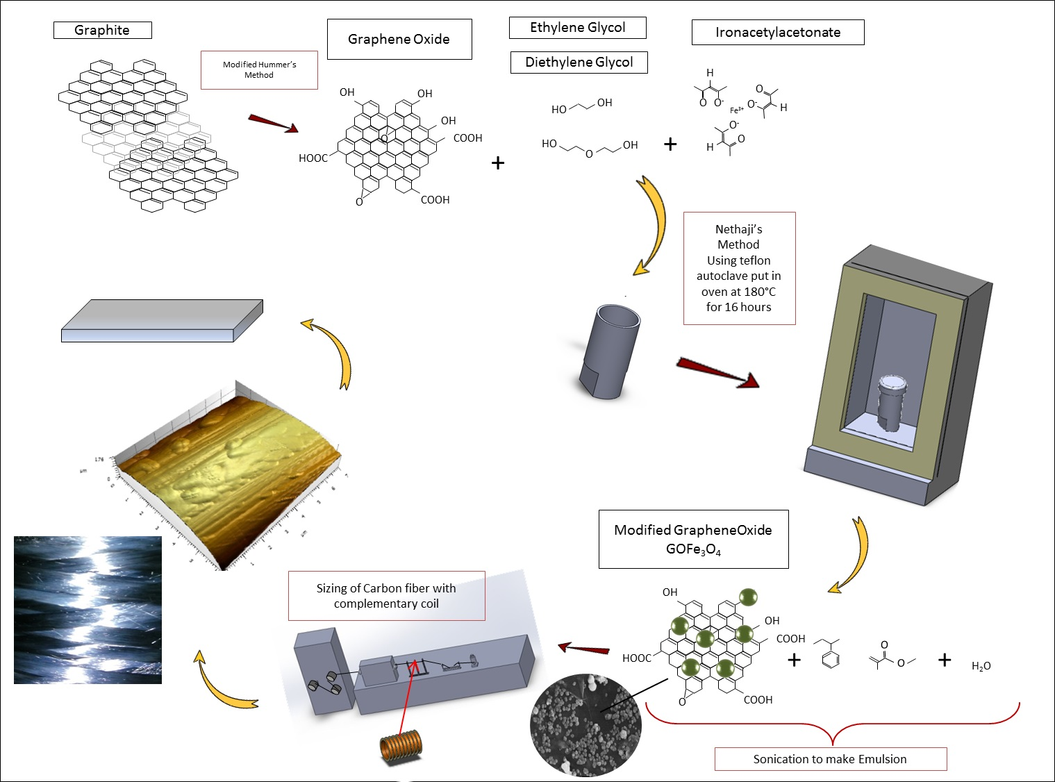
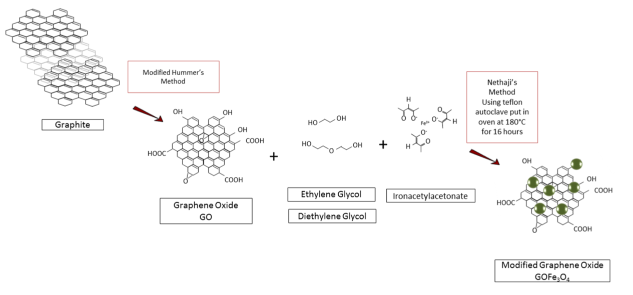
GO@Fe3O4 was prepared using the method developed by Nethaji as shown in Figure 1 [24]. In this method, GO (20 mg) and ironacetylacetonate (200 mg) were added to the mixture of ethylene glycol (40 mL) and diethylene glycol (40 mL), followed by ultrasonic treatment for 35 min. Then, the orange mixture was poured into a 100 mL Teflon autoclave and heated at 180 °C for 16 h in an oven. The modified GO was collected from the obtained green mixture by filtration and washing with DI water for at least 5 times. Finally, the product was dried in vacuum oven at 65 °C for 8 h.
2.3. Sizing of the Tows
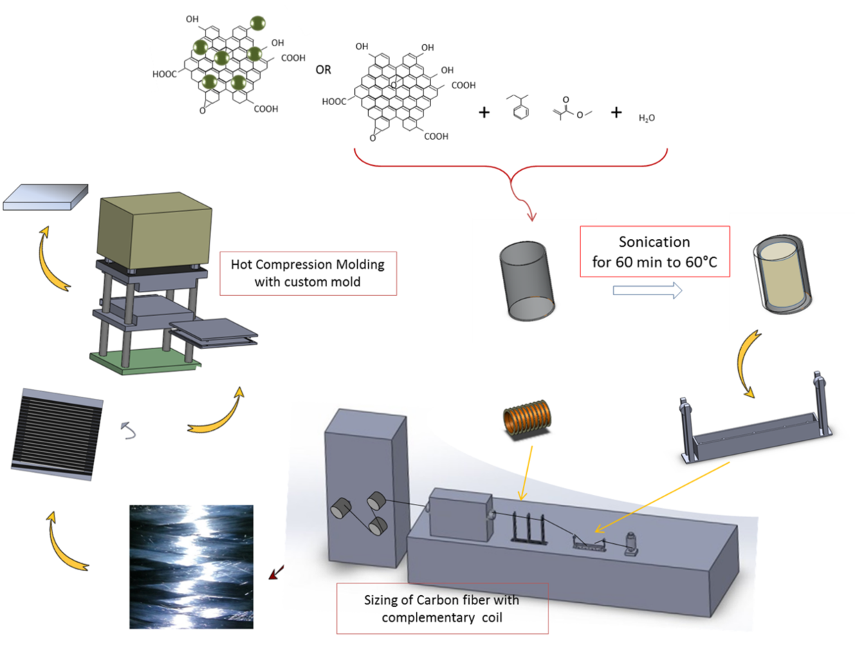
The unsized carbon fiber tows were sized using the lab-scale sizing apparatus as shown in Figure 2. Styrene-acrylic emulsion with 2 wt % solid content was used as sizing agent and the sizing process was performed at 30 °C. For the preparation of modified sizing agent, a desired amount of GO or GO@Fe3O4 (0.2 wt %) was added to the styrene-acrylic emulsion. Before the sizing process, the modified sizing agent was sonicated for 1 h in an ultrasound bath. To orientate the GO@Fe3O4 on sized CFs, a steel coils were fixed on the sizing apparatus (Figure 2) to introduce a magnetic field. The voltage applied to the coin was 4.0 V and the current was 1.5 A. The resulting magnetic flux density was calculated to be 31.6 Gauss.
2.4. Making of the Composite Panels
Composite panels were then made by hot compression molding on a hot press (model HY-10TK, HengYu Instrument Co., Dongguan, China). The sized tows were first winded on an aluminum frame to align the fibers for each ply and then fixed with pressure-sensitive tape before being put between 2 PP films. A ply was then pressed and finally all the plies were pressed in a mold to form 8-layer unidirectional panels for the final laminates. The conditions of temperature/pressure cycles were: 20 min at 0.1 MPa then 2.5 min at 0.5 MPa, then 2.5 min at 1 MPa, and finally 5 min under 2 MPa all at 220 °C and finally, 15 min for cooling at ambient temperature with no pressure. The volume fractions were calculated using the masses of material used and by immersion in isopropanol of the tested coupons.
2.5. Characterization
X-ray photoelectron spectroscopy (XPS) measurements were conducted on a Quantum 2000 Scanning-ESCA Microprobe (Physical Electronics, Ismaning, Germany) with a monochromatic X-ray source at 1486.6 ev (aluminum anode). Fourier transform infrared (FTIR) spectra were recorded on a Spectrum 2 (PerkinElmer, Hong Kong, China) with a wavenumber range from 500 to 4000 cm−1 using attenuated total reflection (ATR) mode. Thermogravimetric analysis (TGA) was performed on a Netzsch 209 Tarsus model (Netzsch, Selb, Germany) under an air atmosphere over a temperature range of 50–600 °C at a heating rate of 10 °C·min−1. Dynamic light scattering measurements were conducted on a BI-200SM (Brookhaven Instruments, New York, NY, USA) with a scattering angle of 173° at 30 °C using a He-Ne laser source (633 nm). AFM observations were carried out on a N9418S 9500 (Keysight Apparatus, Santa Rosa, CA, USA) in tapping mode. The samples were prepared by spin-coating the diluted sizing emulsion onto a freshly cleaved mica sheet. SEM observation was performed on a Quanta 250 field emission scanning electron microscope (ThermoFisher, Hillsboro, OR, USA) with an acceleration voltage of 10 kV. The samples were coated with gold for 90 s before observation. Transmission electron microscopy (TEM) was performed on a JEOL JEM-2100 (JEOL Ltd., Tokyo, Japan) with a 200 kV accelerating voltage. The mechanical properties of the composite panels were measured on a universal testing machine (model ETM 203B-TS, Shenzhen Wance, China). The flexural properties of the composite panels were tested according to ASTM D-790 standard [25]. The sample dimension was 140 mm × 15 mm × 2.5 mm and the crosshead speed was 2.0 mm·min−1. The interlaminar shear strength of the composite panels was measured by short beam shear (SBS) tests following ASTM-D2344 standard [26]. The sample dimension was 15 mm × 5 mm × 2 mm and the crosshead speed was 1.0 mm·min−1. Each reported value was the average of at least 5 specimens.
3. Results and Discussion
3.1. Morphology and Composition of GO@Fe3O4
The morphologies of GO and GO@Fe3O4 are observed by SEM and TEM. SEM micrographs show that GO exhibits a typical sheet-like morphology with some wrinkles (Figure 3a,b). After modification, the magnetic iron oxide particles (with diameters of about 30–100 nm) have successfully anchored onto GO sheets and tend to grow on the defects and edges of GO sheets (Figure 3c,d). This is because most of the carboxylic groups formed at the edge of GO sheet and the iron oxide particles would grow preferentially to the carboxylic groups [27]. Like the SEM observation, the TEM micrographs of GO shows a two-dimensional wrinkled morphology (Figure 4a) with an amorphous structure (Figure 4b). Furthermore metal nanoparticles are more likely to grow at the heterogeneous sites of GO [28]. The TEM observation of GO@Fe3O4 further confirms the attachment of iron oxide particles onto GO surface (Figure 4c). In addition, lattice fringes can be observed in the magnified TEM micrographs of iron oxide particles (Figure 4d), indicating a crystal structure. This is consistent with the observation of iron oxide/graphene oxide nanocomposites reported by Zhang and Wu [29]. XPS is a powerful tool to study the surface chemical compositions of GO and functionalized GO. Figure 5 shows the compositions of GO and GO@Fe3O4 measured by XPS. Compared with GO (Figure 5a), the C/O atomic ratio of GO@Fe3O4 decreases from 1.6 to 1.3, and ferrum element (12 at %) can be detected from GO@Fe3O4 sample (Figure 5b), owing to the attachment of iron oxide particles.
3.2. Effect on the Emulsions and Thermal Stability of TP Sizing Films
Figure 6 shows the effect of grafting of the ferrites on the sizing in bath and final sizing films in terms of emulsion properties and thermal stability. The results of the different sizes of the particles in the emulsions for the acrylic-styrene all containing 2% solids and with 0.5% GO or modified GO of the solid content are given in Figure 6a and a picture of the different emulsions are shown in Figure 6b. From the results obtained by dynamic light scattering (DLS), an average particle diameter size of about 166.1 nm with a polydispersity of 0.103 was obtained for the acrylic-styrene virgin of nanoparticles. With the addition of GO, the average diameter size increased up to 219.2 nm with 0.016. The addition of the GO seems to entail the increase of the particle size which can be easily explained because GO, while being atomically thick, still has a micrometer layer dimension which can account for the high increase in particle size found. With the addition of GO, the polydispersity, however, decreased indicating particles with a much higher homogeneity. This could be due to the fact that the addition of oxygenated functional groups helps in the stabilization of the emulsion. The further introduction of the ferrites modified GO@Fe3O4 also made the average diameter of the particles increase up to 216.3 nm and homogeneity increased to 0.036 polydispersity indicating an improvement compared to the virgin acrylic-styrene emulsion but a slightly less homogenized one compared to the one containing the unmodified GO. This can be explained by the fact that the ferrites may take the place of some of the oxygenated groups participating in stabilizing the emulsion but some of the oxygenated groups remain still improving homogeneity compared to the virgin emulsion.
The TGA thermograms displayed in Figure 6c show that the AS films with no GO incorporated have an onset at about 318 °C and a derivation peak at 341 °C with a second onset at about 498 °C. For the AS + GO sizing film, the first onset was situated at about 367.7 °C with a derivation peak at 399.0 °C with a second onset at about 491.9 °C. And finally for the AS + GO@Fe3O4 sizing film, the first onset was situated at about 350.8 °C with a derivation peak at 385.7 °C with a second onset at about 461.0 °C. From these results it can be concluded that the addition of GO increased the thermal stability of the sizing films by a little less than 50°. The modified GO@Fe3O4 still showed an improvement of about 30 °C of the thermal stability compared to the simple AS sizing film but less than the one with unmodified GO addition. To conclude, the addition of GO improved the thermal stability. However, the ferrite-modified GO improved the thermal stability to a lesser extent. This can be explained by the fact that the basal carbon structure degrades at much higher temperatures than simple acrylic-styrene polymers. But the presence of oxygenated groups may have decreased the less ordered carbon lattice. The temperature degradation found with the addition of the GO is also in accordance with further oxidation of the carbon at these temperatures preceding the degradation. The addition of Fe elements to the GO also favors more rapid oxidation with elevation of the temperature explaining why it decreases somehow the thermal stability compared to the addition of unmodified GO but still improves the thermal stability compared to the acrylic-styrene sizing alone.
3.3. Effect of the Induced Magnetic Field on the Quality of the Sizing
In Figure 7, the surface morphologies and topographies can be seen, showing the effect of the magnetic field. Figure 7a first shows the morphology of unsized fiber used as the reference. The strides of a typical carbon fiber can be observed. The fiber diameter, slightly bigger than 5 microns, can also be obtained and is typical of carbon fiber. In Figure 7b, the topographies of the fibers sized with acrylic-styrene with GO unmodified are shown. It can be seen that the deep strides are no longer present due to the fibers being coated. For AS + GO sizing is coated uniformly. The coating thickness can be estimated approximately by subtracting the 12 µm measured for the sized fiber to the about 6 µm for the unsized one giving a coating thickness of approximately 2 µm. Furthermore, for the fibers sized with the AS + GO with the introduction of a magnetic field, the topography does not seem to change much compared to one without it.
In Figure 7c, the fibers sized with the AS + GO@Fe3O4 without and with introduction of a magnetic field are shown. From the topographies it can be seen that the coated fibers have smaller clusters of sizing than the ones with the unmodified GO. For these fibers sized with AS + GO@Fe3O4 it can be noticed that the introduction of the magnetic field has a major effect on the sizing topography. Indeed, for the highest values of current intensities and thus highest magnetic flux densities, the sizing shape has been totally modified compared to the AS + GO@Fe3O4 without a magnetic field. The coating shows some kind of “drag” effect, the reason for this could be that the sizing with the paramagnetic elements is attracted in the magnetic field as the fibers pass through the coils.
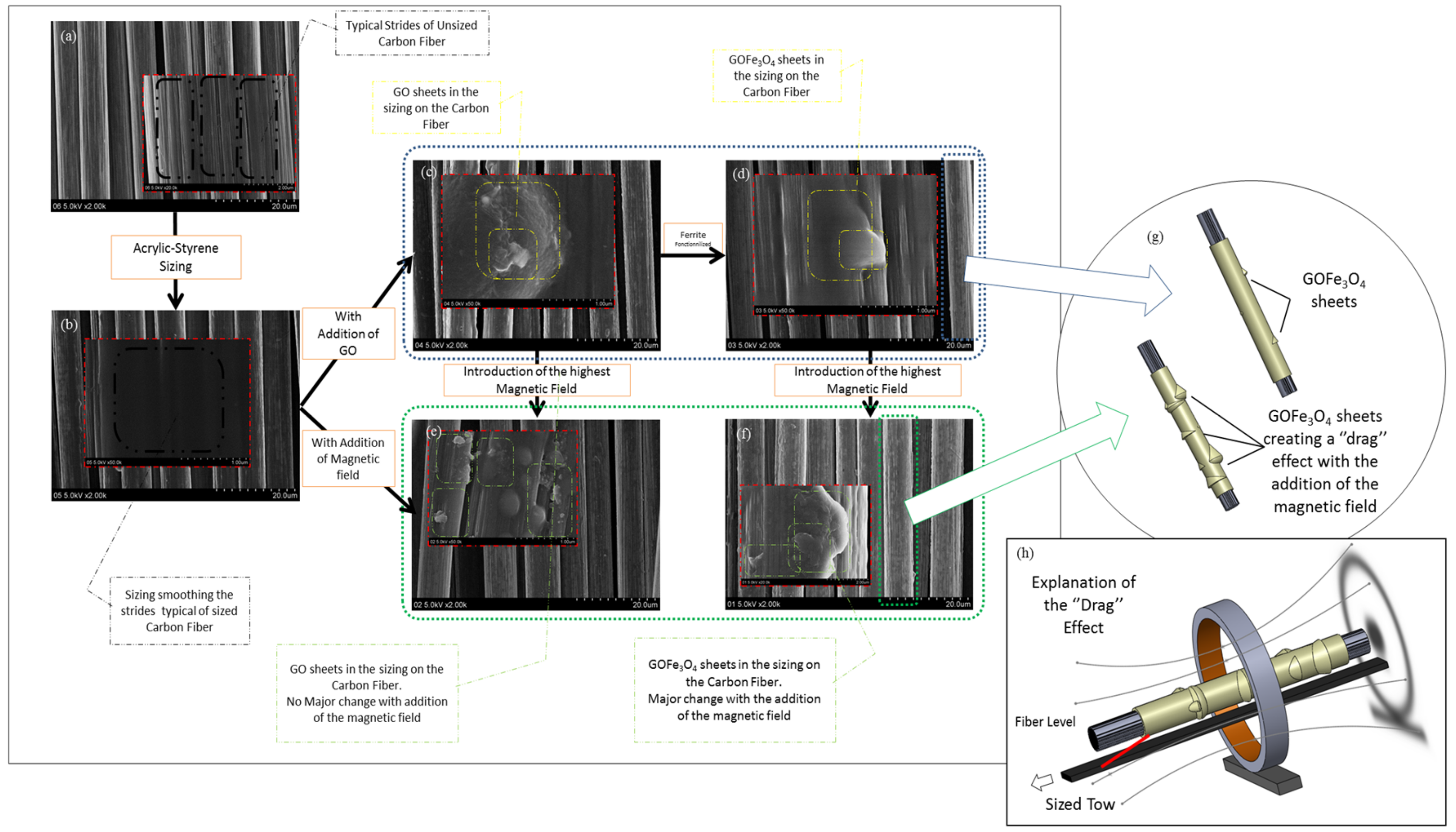
In Figure 8, further FESEM images of the surface of unsized carbon fiber and coated ones give us further information. Firstly, in Figure 8a, we can see once again the typical strides of the unsized carbon fiber and in Figure 8b the thin coating film of AS covering the strides. The presence of GO sheets is further observed in Figure 8c (highlighted in the yellow box). The introduction of the highest magnetic field (powered with 1.5 A) did not change significantly the morphology of the fiber and flakes of GO are still observed as shown on Figure 8e. For the ferrite modified GO@Fe3O4, without the magnetic field, the morphology of the fiber is quite similar to the unmodified AS + GO one. A sheet of GO@Fe3O4 can still be observed as highlighted in by the yellow box. When the highest magnetic field is introduced during sizing for the GO@Fe3O4, a major change to the morphology of the fiber is observed. This kind of drag effect already observed by AFM is confirmed and the joint orientation of the magnetic field couple with the direction of the sizing line may lead to the agglomeration of GO@Fe3O4 sheets and then their relief when exiting the magnetic field creating this specific morphology.
3.4. Effect of the Ferrites and Induced Magnetic Field on the Final Mechanical Properties
In Figure 9 are displayed the results obtained giving the influence of the GO and modified GO without a magnetic field and with the highest magnetic field during sizing. All of them have similar mass fraction content of reinforcement ranging from about 33% to 36% (the details are given in the supplementary information). For the composites prepared from the sized tows with no addition of a magnetic field, it can be observed that the addition of GO increases slightly the flexural strength by about 7%, from about 130.5 MPa to 139.9 MPa. The ferrite modified GO, however, seems to decrease the flexural strength (more than 20% from 130.5 MPa to 99.9 MPa). This could be explained by two reasons: The first one is the possible damage of the fibers during the sizing with the addition of the GO, resulting in fibers having more inherent damage in turn decreasing the final strength of the laminates themselves. This could account for the decrease observed. Several researchers have shown the possible influence of the sizing on the laminate strength and have proposed similar conclusions [30]. The second reason explaining why the unmodified GO shows an improved flexural strength could be that however damaging the fiber, the introduction of GO conjointly improves the adhesion by the introduction of the functional oxygenated. However, the ferrites may induce more damage to the fiber and the less oxygenated groups present may lead to this decrease in flexural strength.
With the addition of a magnetic field powered with 1.5 A during the sizing, the final laminates have a 29% improved flexural strength compared to their equivalents without it. Nevertheless, they are still inferior to the virgin ones and to the unmodified GO doped ones. This could be explained by the fact that the change of topography as shown previously may increases the fiber-matrix adhesion resulting in improved flexural strength, however the damage made to the fiber by the presence of the ferrites elements may still explain with the flexural strength is still lower than the virgin and AS + GO only ones.
3.5. Effect of the Ferrites and Induced Magnetic Field on the Fiber/Matrix Interphase
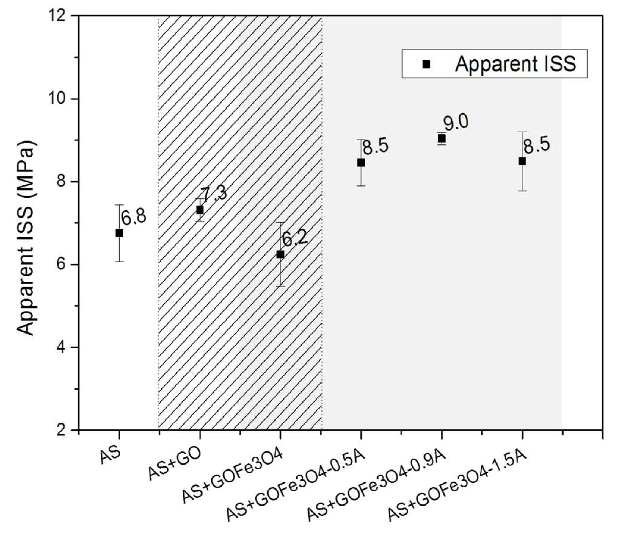
In Figure 10, the test results for the short beam shear test giving the interlaminar shear strength (ISS) are shown. All of them have similar mass fraction content of reinforcement ranging from about 33% to 36% (The details are given in the supplementary information). From these results, it can be seen that the introduction of GO increases the ISS. Even if the coefficient of variation is not very small, a clear trend may still be identified—the further introduction of a magnetic field also to improve the ISS. The ferrite modified GO without introduction of a magnetic field seems to decrease slightly the value of the ISS. Nonetheless, with further introduction of the magnetic field and an increase of the current intensities supplying the magnetic field, the ISS increased by about 20%. The increase for the ISS value for the ferrite modified GO@Fe3O4 could be explained once again by the modification of the sizing aspect as shown by the AFM topographies resulting in the formation of an interphase more readily.
4. Conclusions
In this work, GO and ferrite modified GO@Fe3O4 were studied. Their different effects on sizing with the introduction of a magnetic field during the sizing process were obtained as well as final interfacial properties in continuous carbon-fiber-reinforced thermoplastic composites. The results show that the GO had an influence firstly on the thermal stability of the sizing films with an increase with the addition of GO. The thermal stability decreased slightly for the GO@Fe3O4 compared to GO, even if it was still improved in regards to the virgin one. Furthermore, the introduction of a magnetic field seemed to have a major influence on the topography of the sizing itself containing the modified GO@Fe3O4 resulting in an improvement of the final interfacial properties with higher ISS and flexural strength. The results overall show that the addition of GO and GO@Fe3O4 coupled with a magnetic field during sizing process are suitable to improve interfacial properties.
Acknowledgments
The authors of this paper would like to thank Beijing Eastern Acrylic Chemical Technology Co. Ltd. for providing the sizing materials and HengShen for producing the unsized Carbon Fiber. This research was partly supported by the Chinese Scholarship Council (CSC) which is gratefully acknowledged.
Author Contributions
S.B., Y.W., Y.Q. and W.L. conceived and designed the experiments; S.B. performed the experiments; S.B., Y.W. and W.L. analyzed the data; Y.W., W.L. and X.H. contributed reagents/materials/analysis tools; S.B., W.L., Y.W. and Q.J. wrote the paper.
Conflicts of Interest
The authors declare no conflict of interest.
References
- Chung, D.D.L. Composite Materials Science and Applications, 2nd ed.; Springer Science & Business Media: Berlin, Germany, 2010. [Google Scholar]
- Donnet, J.B.; Ransal, R.C. Carbon Fibers; CRC Press: Bocca Raton, FL, USA, 1990. [Google Scholar]
- Kandola, B.; Sarker, F.; Luangtriratana, P.; Myler, P. Thermal protection of carbon fiber-reinforced composites by ceramic particles. Coatings 2016, 6, 22. [Google Scholar] [CrossRef]
- Plastics, R. New Developments Help Composites Compete; Elsevier Science Ltd.: Amsterdam, The Netherlands, 2003; Volume 47, pp. 27–31. [Google Scholar]
- Brandt, J. The use of high-performance thermoplastic composites for structural aerospace applications. In Proceedings of the 9th Int Conference on Composite Materials, Madrid, Spain, 12–16 July 1993; pp. 143–150. [Google Scholar]
- Nairn, J.A.; Liu, Y.C.; Galiotis, C. Analysis of stress transfer from the matrix to the fiber through an imperfect interface: Application to raman data and the single-fiber fragmentation test. In Fiber, Matrix, and Interface Properties, ASTM STP 1290; Spragg, C.J., Drzal, L.T., Eds.; ASTM International: West Conshohocken, PA, USA, 1996; pp. 47–65. [Google Scholar]
- Yokobori, A.T.; Takeda, H.; Adachi, T.; Ha, J.C.; Yokobori, T. Characteristics of fatigue life and damage accumulation of shory-fiber reinforced polymer composites. In Fiber, Matrix, and Interface Properties, ASTM STP 1290; Spragg, C.J., Drzal, L.T., Eds.; ASTM International: West Conshohocken, PA, USA, 1996; pp. 152–167. [Google Scholar]
- Pitkethly, M.J. The use of interfacial test methods in composite materials development. In Fiber, Matrix, and Interface Properties, ASTM STP 1290; Spragg, C.J., Drzal, L.T., Eds.; ASTM International: West Conshohocken, PA, USA, 1996; pp. 34–46. [Google Scholar]
- Sharma, M.; Gao, S.; Mäder, E.; Sharma, H.; Wei, L.Y.; Bijwe, J. Carbon fiber surfaces and composite interphases. Compos. Sci. Technol. 2014, 102, 35–50. [Google Scholar] [CrossRef]
- Yuan, H.; Zhang, S.; Lu, C. Surface modification of carbon fibers by a polyether sulfone emulsion sizing for increased interfacial adhesion with polyether sulfone. Appl. Surf. Sci. 2014, 317, 737–744. [Google Scholar] [CrossRef]
- Zhang, R.L.; Huang, Y.D.; Liu, L.; Tang, Y.R.; Su, D.; Xu, L.W. Effect of the molecular weight of sizing agent on the surface of carbon fibres and interface of its composites. Appl. Surf. Sci. 2011, 257, 1840–1844. [Google Scholar] [CrossRef]
- Han, S.H.; Oh, H.J.; Kim, S.S. Evaluation of fiber surface treatment on the interfacial behavior of carbon fiber-reinforced polypropylene composites. Compos. Part B Eng. 2014, 60, 98–105. [Google Scholar] [CrossRef]
- Yao, T.-T.; Wu, G.-P.; Song, C. Interfacial adhesion properties of carbon fiber/polycarbonate composites by using a single-filament fragmentation test. Compos. Sci. Technol. 2017, 149, 108–115. [Google Scholar] [CrossRef]
- Woodhead, A.L.; de Souza, M.L.; Church, J.S. An investigation into the surface heterogeneity of nitric acid oxidized carbon fiber. Appl. Surf. Sci. 2017, 401, 79–88. [Google Scholar] [CrossRef]
- Andideh, M.; Esfandeh, M. Statistical optimization of treatment conditions for the electrochemical oxidation of PAN-based carbon fiber by response surface methodology: Application to carbon fiber/epoxy composite. Compos. Sci. Technol. 2016, 134, 132–143. [Google Scholar] [CrossRef]
- Askeland, P.A.; Fukushima, H.; Rich, M.; Drzal, L.T. UV Ozone Surface Modification of Carbon Based Reinforcements for Composite Materials; Composite Materials and Structures Center, Michigan State University: East Lansing, MI, USA, 2004; p. 9. [Google Scholar]
- Fan, W.; Wang, Y.; Wang, C.; Chen, J.; Wang, Q.; Yuan, Y.; Niu, F. High efficient preparation of carbon nanotube-grafted carbon fibers with the improved tensile strength. Appl. Surf. Sci. 2016, 364, 539–551. [Google Scholar] [CrossRef]
- Li, F.; Liu, Y.; Qu, C.-B.; Xiao, H.-M.; Hua, Y.; Sui, G.-X.; Fu, S. Enhanced mechanical properties of short carbon fiber reinforced polyethersulfone composites by graphene oxide coating. Polymer 2015, 59, 155–165. [Google Scholar] [CrossRef]
- Zhang, S.; Liu, W.B.; Hao, L.F.; Jiao, W.C.; Yang, F.; Wang, R.G. Preparation of carbon nanotube/carbon fiber hybrid fiber by combining electrophoretic deposition and sizing process for enhancing interfacial strength in carbon fiber composites. Compos. Sci. Technol. 2013, 88, 120–125. [Google Scholar] [CrossRef]
- Zhang, X.; Fan, X.; Yan, C.; Li, H.; Zhu, Y.; Li, X.; Yu, L. Interfacial microstructure and properties of carbon fiber composites modified with graphene oxide. ACS Appl. Mater. Interfaces 2012, 4, 1543–1552. [Google Scholar] [CrossRef] [PubMed]
- Zhu, Y.; Murali, S.; Cai, W.; Li, X.; Suk, J.W.; Potts, J.R.; Ruoff, R.S. Graphene and graphene oxide: Synthesis, properties, and applications. Adv. Mater. 2010, 22, 3906–3924. [Google Scholar] [CrossRef] [PubMed]
- Chen, D.; Feng, H.; Li, J. Graphene oxide: Preparation, functionalization, and electrochemical applications. Chem. Rev. 2012, 112, 6027–6053. [Google Scholar] [CrossRef] [PubMed]
- Hummers, W.S.; Offeman, R.E. Preparation of graphitic oxide. J. Am. Chem. Soc. 1958, 80, 1339. [Google Scholar] [CrossRef]
- Nethaji, S.; Sivasamy, A. Graphene oxide coated with porous iron oxide ribbons for 2,4-Dichlorophenoxyacetic acid (2,4-D) removal. Ecotoxicol. Environ. Saf. 2017, 138, 292–297. [Google Scholar] [CrossRef] [PubMed]
- ASTM D790-17 Standard Test Methods for Flexural Properties of Unreinforced and Reinforced Plastics and Electrical Insulating Materials; ASTM International: West Conshohocken, PA, USA, 2017.
- ASTM D2344 Standard Test Method for Short-Beam Strength of Polymer Matrix Composite Materials and Their Laminates; ASTM International: West Conshohocken, PA, USA, 2016.
- He, F.; Fan, J.; Ma, D.; Zhang, L.; Leung, C.; Chan, H.L. The attachment of Fe3O4 nanoparticles to graphene oxide by covalent bonding. Carbon 2010, 48, 3139–3144. [Google Scholar] [CrossRef]
- Luan, V.H.; Bae, D.; Han, J.H.; Lee, W. Mussel-inspired dopamine-mediated graphene hybrid with silver nanoparticles for high performance electrochemical energy storage electrodes. Compos. Part B Eng. 2018, 134, 141–150. [Google Scholar] [CrossRef]
- Zhang, B.; Li, Y.; Wu, T.; Sun, D.; Chen, W.; Zhou, X. Magnetic iron oxide/graphene oxide nanocomposites: Formation and interaction mechanism for efficient removal of methylene blue and p-tert-butylphenol from aqueous solution. Mater. Chem. Phys. 2018, 205, 240–252. [Google Scholar] [CrossRef]
- Dong, R.; Liu, L. Preparation and properties of acrylic resin coating modified byfunctional graphene oxide. Appl. Surf. Sci. 2016, 368, 378–387. [Google Scholar] [CrossRef]
Figure 1.
Schematic illustration of preparation of GO@Fe3O4.

Figure 2.
Schematic sizing process and making of the laminates.

Figure 3.
Visualization of the effect of the grafting of the ferrites and ferrite structure using field emission scanning electron microscopy (FESEM) for (a) unmodified GO ×20,000, (b) unmodified GO ×70,000 and (c) modified GO@Fe3O4 ×20,000 and (d) modified GO@Fe3O4 ×70,000.
Figure 3.
Visualization of the effect of the grafting of the ferrites and ferrite structure using field emission scanning electron microscopy (FESEM) for (a) unmodified GO ×20,000, (b) unmodified GO ×70,000 and (c) modified GO@Fe3O4 ×20,000 and (d) modified GO@Fe3O4 ×70,000.
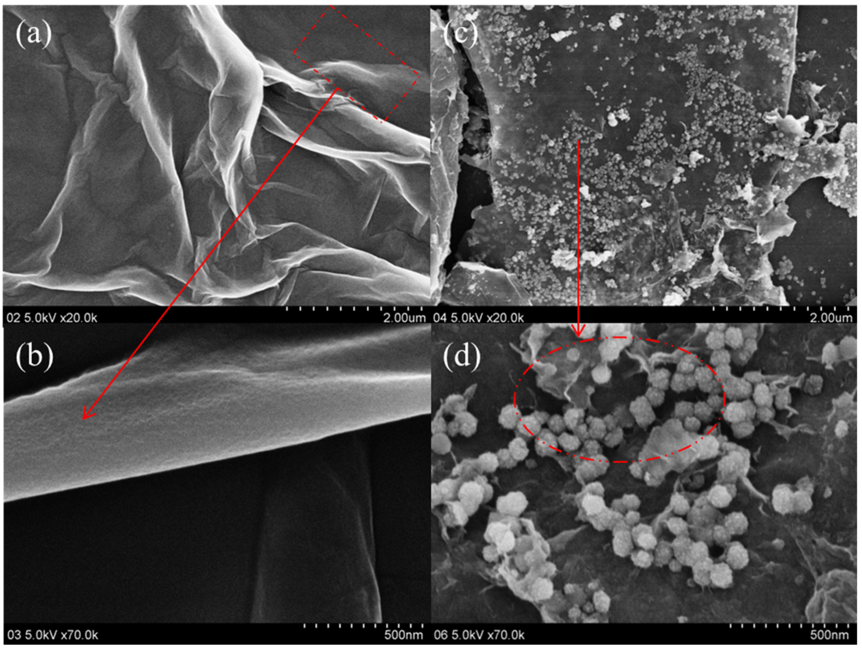
Figure 4.
Representative transmission electron microscopy (TEM) and high-resolution transmission electron microscopy (HRTEM) micrographs of GO (a,b) and GO@Fe3O4 (c,d).
Figure 4.
Representative transmission electron microscopy (TEM) and high-resolution transmission electron microscopy (HRTEM) micrographs of GO (a,b) and GO@Fe3O4 (c,d).
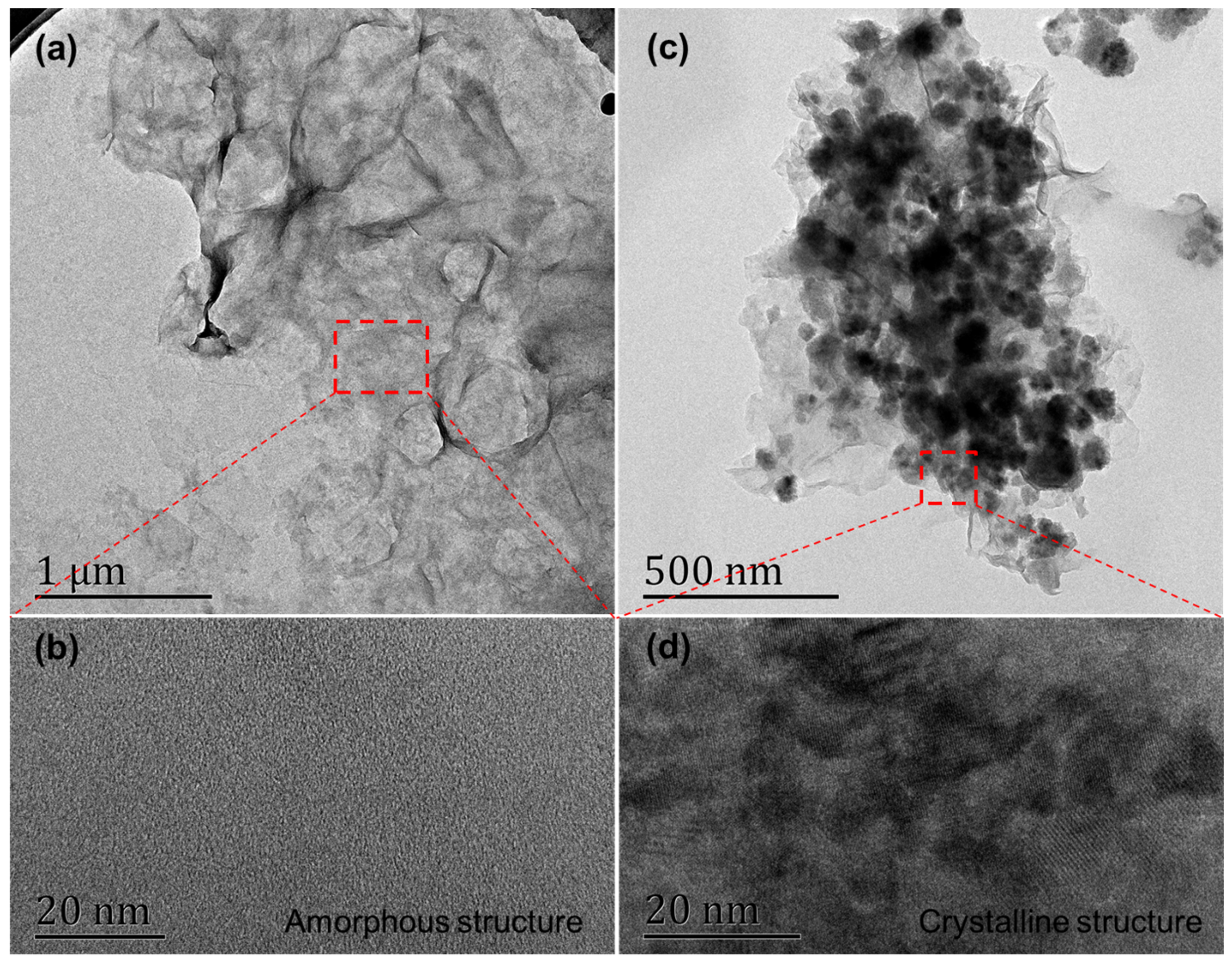
Figure 5.
Compositions and C 1s profiles of GO (a) and GO@Fe3O4 (b) powders measured by X-ray photoelectron spectroscopy (XPS).
Figure 5.
Compositions and C 1s profiles of GO (a) and GO@Fe3O4 (b) powders measured by X-ray photoelectron spectroscopy (XPS).
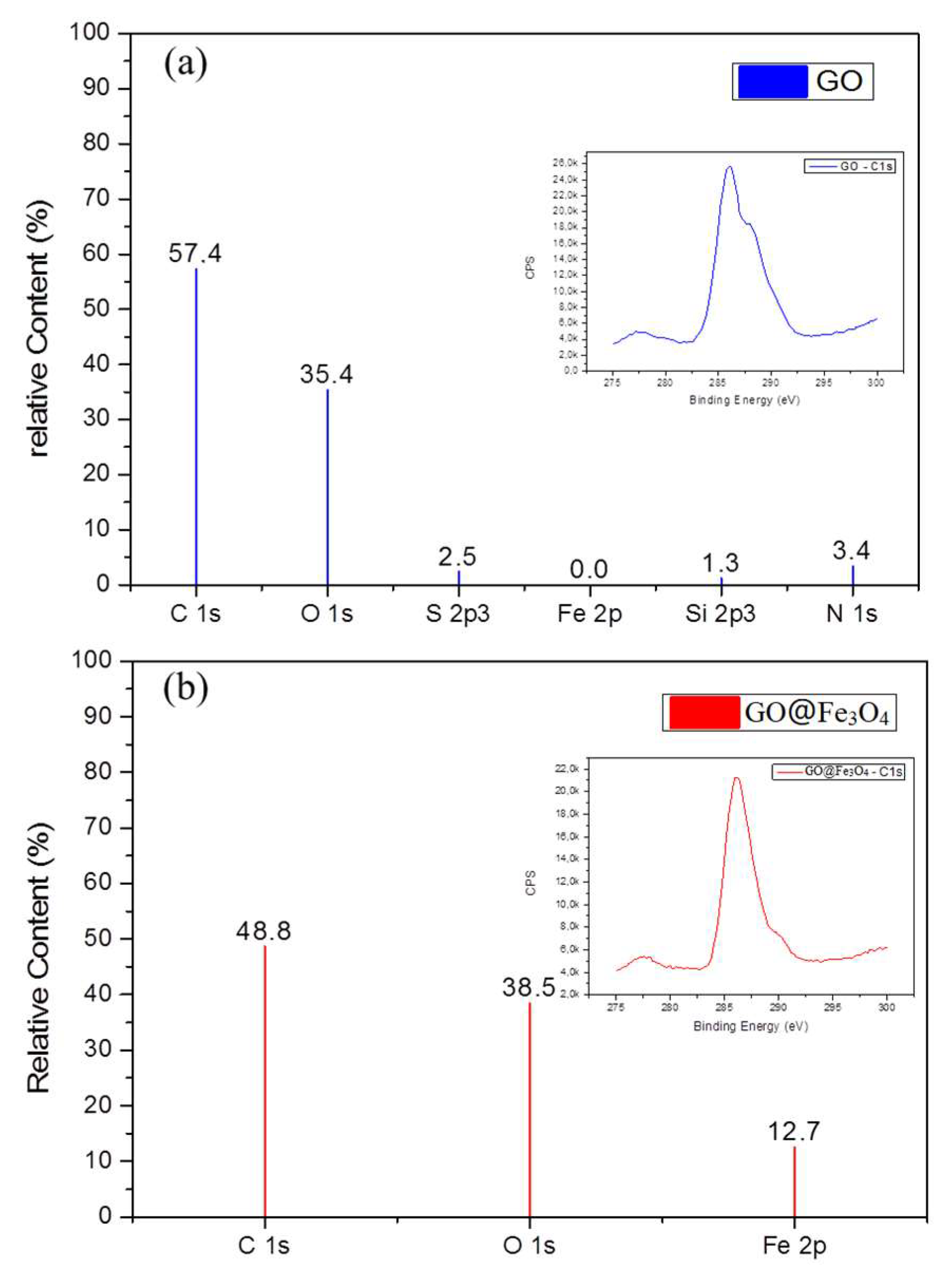
Figure 6.
Results showing the properties of the emulsion and dried films coating the fibers with (a) the effect of the ferrites on the particle diameter size in emulsion and (b) photos of sizing formulations and (c) thermal stability of the sizing films with different GO.
Figure 6.
Results showing the properties of the emulsion and dried films coating the fibers with (a) the effect of the ferrites on the particle diameter size in emulsion and (b) photos of sizing formulations and (c) thermal stability of the sizing films with different GO.
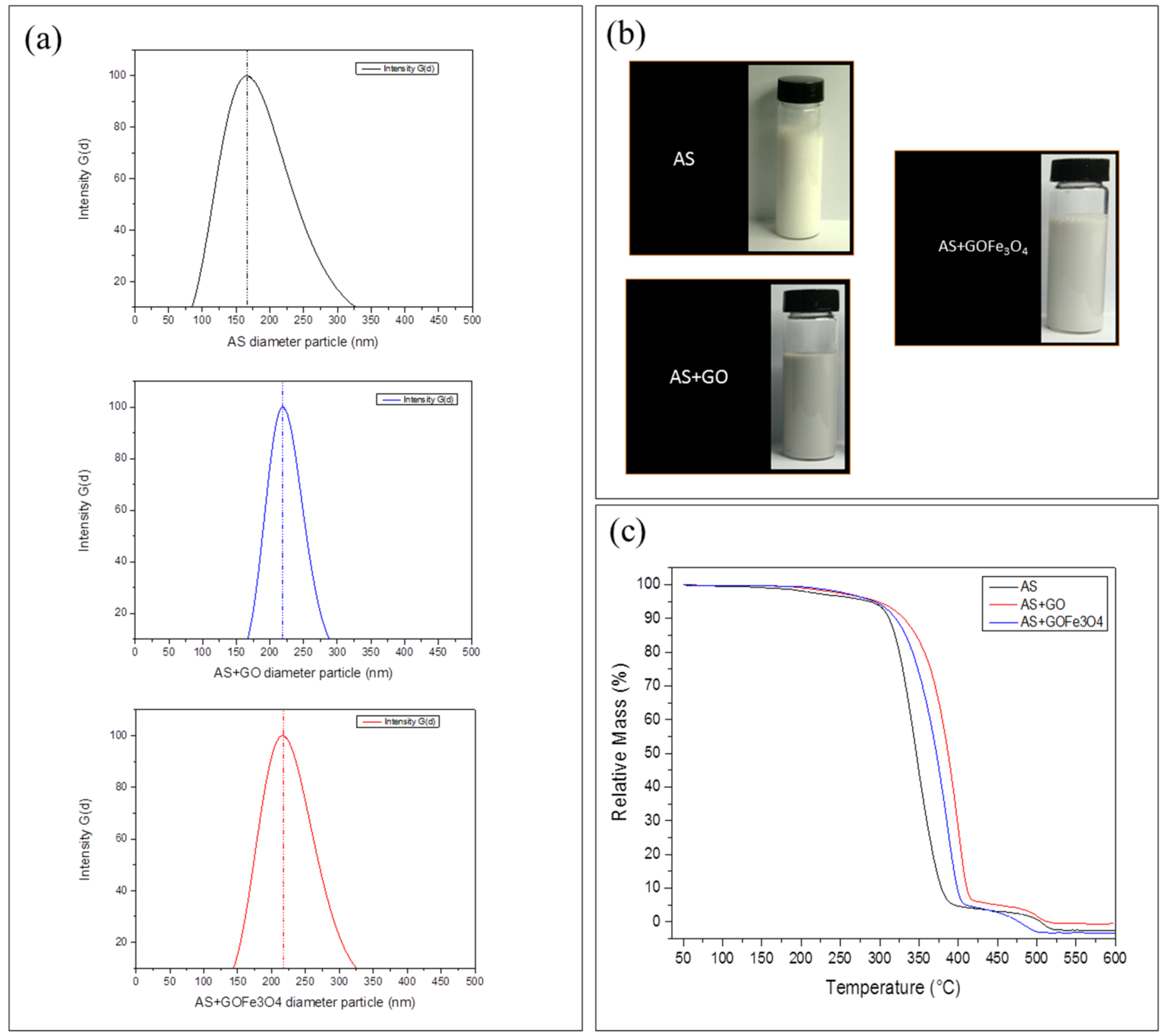
Figure 7.
Effect of magnetic field on the coating quality of the fibers with the GO, atomic force microscopy (AFM) topographies of (a) unsized fiber for reference; (b) sized fiber with AS + GO; (c) sized with AS + GO under a magnetic field powered under 1.5 A and 0.9 A.
Figure 7.
Effect of magnetic field on the coating quality of the fibers with the GO, atomic force microscopy (AFM) topographies of (a) unsized fiber for reference; (b) sized fiber with AS + GO; (c) sized with AS + GO under a magnetic field powered under 1.5 A and 0.9 A.
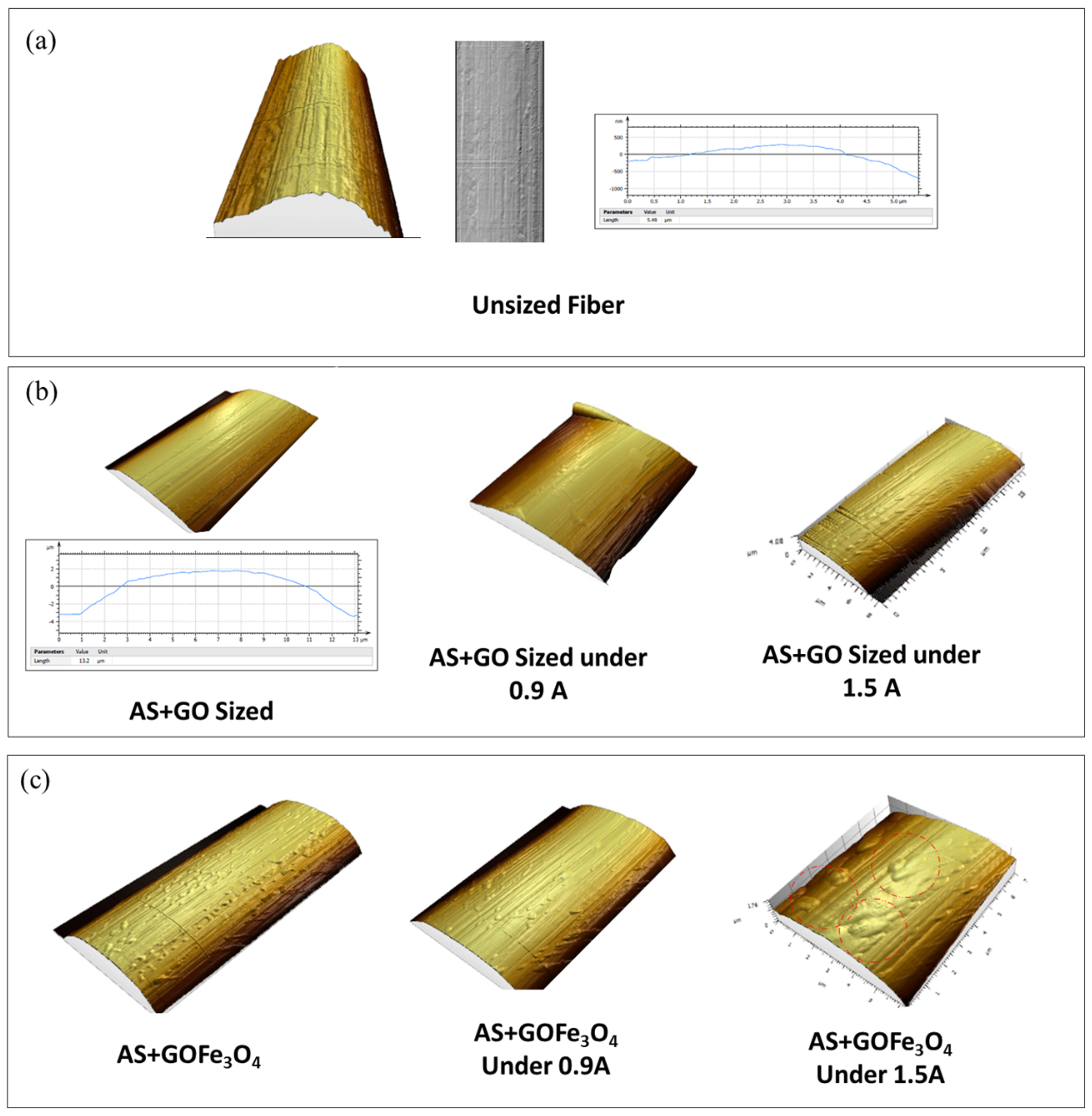
Figure 8.
Effect of magnetic field on the coating quality of the fibers using (a) FESEM image of unsized fiber (b) FESEM image of fiber sized with the acrylic-styrene only (c) FESEM image of fiber sized with the acrylic-styrene with GO (d) FESEM image of fiber sized with the acrylic-styrene with GOFe3O4 (e) FESEM image of fiber sized with the acrylic-styrene with GO and magnetic field; (f) FESEM image of fiber sized with the acrylic-styrene with GOFe3O4 and magnetic field; (g) schematic drawing of the drag effect and (h) schematic explanation of the drag effect.

Figure 9.
Effect of the magnetic field on the flexural Strength of the final laminates.
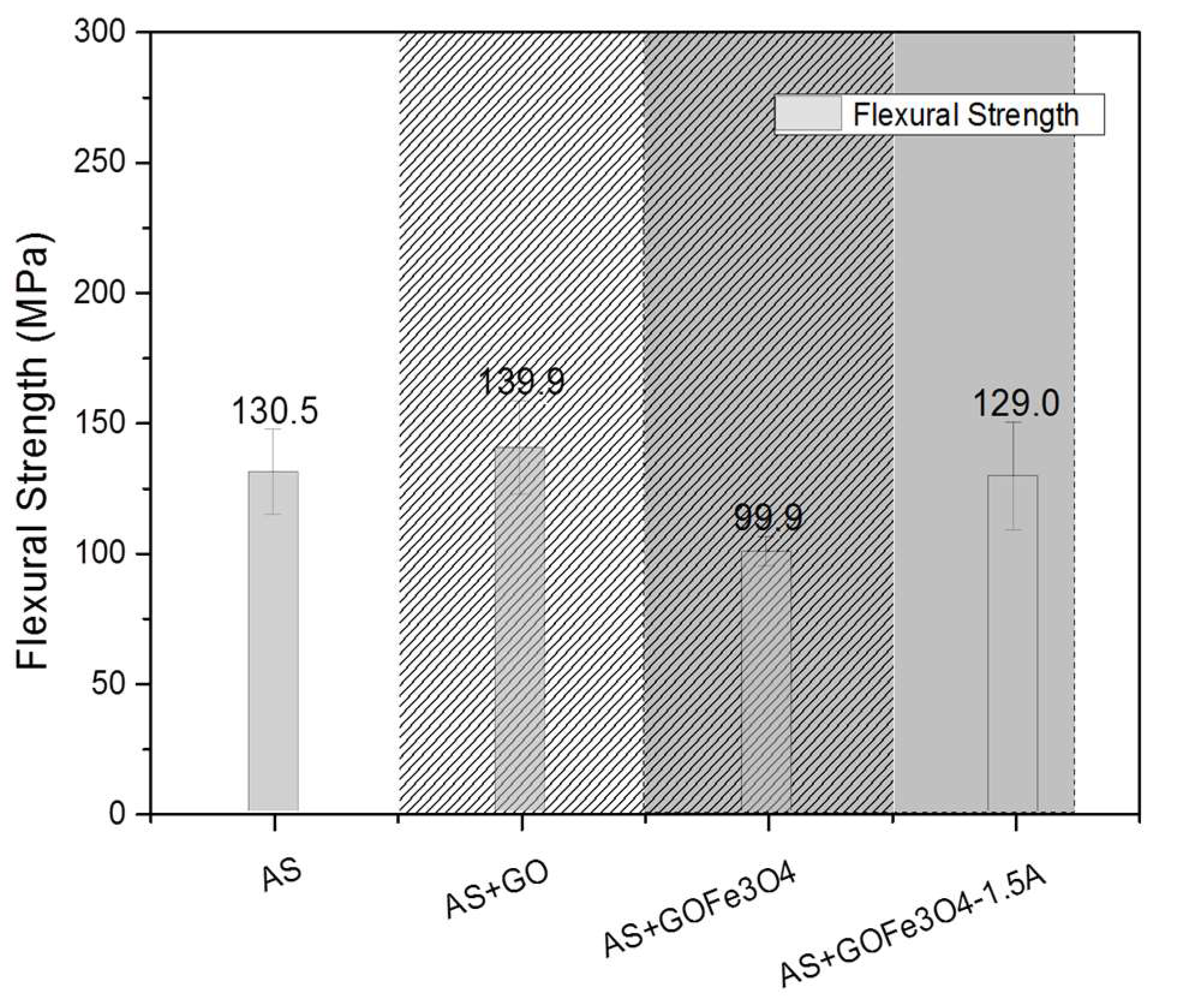
Figure 10.
Effect of ferrites and magnetic field on the fiber-matrix interphase with results obtained for the ISS using SBS.
Figure 10.
Effect of ferrites and magnetic field on the fiber-matrix interphase with results obtained for the ISS using SBS.

© 2018 by the authors. Licensee MDPI, Basel, Switzerland. This article is an open access article distributed under the terms and conditions of the Creative Commons Attribution (CC BY) license (http://creativecommons.org/licenses/by/4.0/).
Share and Cite
MDPI and ACS Style
Bowman, S.; Hu, X.; Jiang, Q.; Qiu, Y.; Liu, W.; Wei, Y. Effects of Graphene-Oxide-Modified Coating on the Properties of Carbon-Fiber-Reinforced Polypropylene Composites. Coatings 2018, 8, 149. https://doi.org/10.3390/coatings8040149
AMA Style
Bowman S, Hu X, Jiang Q, Qiu Y, Liu W, Wei Y. Effects of Graphene-Oxide-Modified Coating on the Properties of Carbon-Fiber-Reinforced Polypropylene Composites. Coatings. 2018; 8(4):149. https://doi.org/10.3390/coatings8040149
Chicago/Turabian StyleBowman, Sean, Xiaoyu Hu, Qiuran Jiang, Yiping Qiu, Wanshuang Liu, and Yi Wei. 2018. "Effects of Graphene-Oxide-Modified Coating on the Properties of Carbon-Fiber-Reinforced Polypropylene Composites" Coatings 8, no. 4: 149. https://doi.org/10.3390/coatings8040149
Note that from the first issue of 2016, this journal uses article numbers instead of page numbers. See further details here.