Effect of Electrode Coating with Graphene Suspension on Power Generation of Microbial Fuel Cells

1
Department of Power Mechanical Engineering, National Tsing Hua University, Hsinchu 30013, Taiwan
2
Department of Mechanical Engineering, National United University, Miaoli 36003, Taiwan
*
Author to whom correspondence should be addressed.
Coatings 2018, 8(7), 243; https://doi.org/10.3390/coatings8070243
Submission received: 1 April 2018
/
Revised: 3 June 2018
/
Accepted: 18 June 2018
/
Published: 10 July 2018
(This article belongs to the Special Issue Graphene and Other 2D Layered Nanomaterial-Based Films: Synthesis, Properties and Applications)
Abstract
:Microbial fuel cells (MFCs), which can generate low-pollution power through microbial decomposition, are a potentially vital technology with applications in environmental protection and energy recovery. The electrode materials used in MFCs are crucial determinants of their capacity to generate electricity. In this study, we proposed an electrode surface modification method to enhance the bacterial adhesion and increase the power generation in MFCs. Graphene suspension (GS) is selected as modifying reagent, and thin films of graphene are fabricated on an electrode substrate by spin-coating. Application of this method makes it easy to control the thickness of graphene film. Moreover, the method has the advantage of low cost and large-area fabrication. To understand the practicality of the method, the effects of the number of coating layers and drying temperature of the graphene films on the MFCs’ performance levels are investigated. The results indicate that when the baking temperature is increased from 150 to 325 °C, MFC power generation can increase approximately 4.5 times. Besides, the maximum power density of MFCs equipped with a four-layer graphene anode is approximately four times that of MFCs equipped with a two-layer graphene anode. An increase in baking temperature or number of coating layers of graphene films enhances the performance of MFC power generation. The reason can be attributed to the graphene purity and amount of graphene adhering to the surface of electrode.
1. Introduction
In the last decade, renewable energy sources that emit little pollution have been extensively studied due to shortages of energy and the rise of environmental awareness. Microbial fuel cells (MFCs) are one solution to this problem. MFCs utilize microorganisms as catalysts to break the chemical bonds of organic compounds and harvest electrical energy [1]. In the 1910s, the concept of applying microorganisms as catalysts in fuel cell systems was first explored [2]. The technology of fuel cell systems was not yet mature, and systems could produce only weak electricity. Thus, MFC technology did not receive any public attention at that time. Breakthroughs in fuel cell technology and energy crises have led to renewed interest in the development of MFCs.
The advantage of microbial fuel cells is that they can treat wastewater and produce electricity at the same time. Different levels of wastewater have been treated using MFCs technology, such as distillery wastewater [3], industrial wastewater [4], livestock wastewater [5], and domestic wastewater [6,7]. In these studies, bioelectricity generation is mainly achieved using natural microflora. The type of natural microflora affects the efficiency of wastewater treatment and electricity generation. Thus, some studies use cultivated bacteria to reduce biological variability as a source of noise. Escherichia coli (E. coil) is a commonly used cultivated bacteria for the study of electrode design [8,9,10].
The high cost of fabrication and low power output may be major obstacles toward the commercialization of MFCs. Some factors that affect the cost of an MFC include the type of reactor, the membrane separator, the electrode materials, and catalyst materials [11,12,13]. Typical MFC configurations include double-chamber MFCs [8], flat-plate MFCs [6], and single-chamber MFCs [7,9,10,14]. Single-chamber MFC configurations have the advantage of higher power generation and smaller volume than double-chamber MFCs [15]. Moreover, single-chamber MFC configurations can reduce cost by eliminating proton exchange membranes (PEMs) [14]. Thus, single-chamber MFCs have potential for commercial development.
The power output of an MFC is dependent on operational conditions and several factors, such as microbial inoculation, electrode materials, ionic concentration, catalyst, internal resistance, and electrode spacing [16,17,18,19]. Among these factors, electrode materials exert critical effects on the active surface utilization. Metal electrodes, such as stainless steel and titanium, have become a research focus due to their high electrical conductivity, which can effectively collect electrons and reduce ohmic loss [9,20]. Moreover, in MFC systems, electrons are generated by electrochemically active microorganisms at the interfaces between anodic surfaces and microbes [21,22]. Microorganisms grown as a biofilm on the anode surface are crucial for the performance of MFCs. Biofilm is like an electron acceptor of anode, which directly affects substrate metabolism and electronic collection capability [23,24]. For facilitating bacterial attachment and subsequent biofilm formation, three-dimensional metal, for example stainless steel mesh (SSM) [9,18,19,20,21,22], has been used as an electrode substrate. Electrode surface coatings with nanomaterials have become a reliable and effective approach for enhancing the power output and reliability of MFCs.
Graphene has been intensively studied as a possible electrode material for MFCs [8,9,10,25] due to its properties, namely high electrical conductivity, surface area, and stability. Anodes modified with graphene can improve the electrode surface area, the adhesion of bacteria, and the efficiency of electron transfer [8]. For cathode modification, graphene can be used as a catalyst for oxygen reduction reactions [9,10].
Most published studies have used the soaking method and chemical vapor deposition (CVD) to coat graphene onto the surfaces of electrodes. Although the soaking method has the advantage of being a simple process, it is difficult to control the coating thickness of the graphene. Moreover, during the soaking process, both waste and pollution from the graphene solution are major issues. CVD easily controls the deposition thickness of graphene and has superior deposition uniformity. However, expensive equipment and relatively long deposition times are not conducive to commercial development. Due to this coating process problem, the current study proposed a coating method for graphene deposition on electrode surfaces. Graphene suspension (GS) is spin-coated on SSM electrodes to obtain large and uniform graphene films. The effects of the number of coating layers and drying temperature of the graphene films on the MFCs’ performance levels are the primary research content required to understand the practicality of this method. The power densities of the MFCs under different electrode spin coating conditions were evaluated as the performance indices.
2. Materials and Methods
2.1. MFC System and Preparation of Electrodes
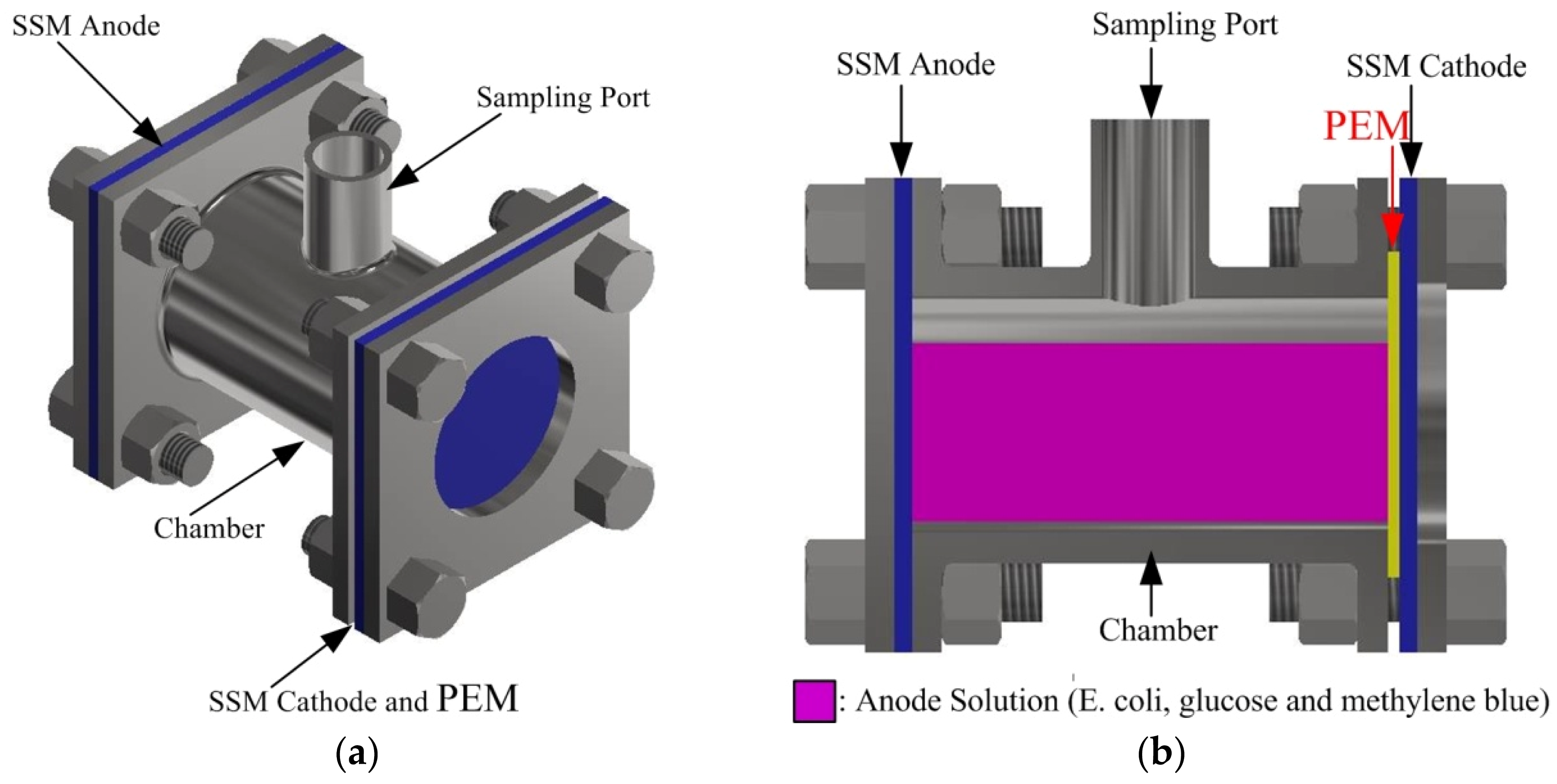
The single-chamber MFC that we studied is shown in Figure 1. Figure 1a shows a schematic of the air-cathode MFC, which is cylindrical with a diameter of 40 mm, a length of 60 mm, and a total reactor volume of approximately 75 mL. Figure 1b shows a cross-section of the MFC. The cathode electrode and PEM (Nafion 117, Dupont Co., Wilmington, DE, USA) were fixed on the air-side, whereas the anode electrode was fixed on the opposite side of the cylindrical chamber. The base material of the electrodes was 304 SSM (E Shie Zong Co., Ltd., Taiwan) with an average diameter of approximately 30 μm (400 mesh). The modified material for SSM electrode is GS (S-WB30, Enerage Inc., Yilan, Taiwan). S-WB30 was prepared using 3 wt % of graphene in water as a solvent. The specific surface area of graphene was larger than 15 m2/g. The average sheet thickness of graphene sheets was over 5 nm, and the lateral size of graphene sheets was approximately 20 μm. To coat the GS on the surfaces of the SSM electrodes, we proposed a surface modification method. For anodic modification, the SSM was washed by acetone, alcohol, and deionized water and then dried by a hot plate at 150 °C. After the cleaning process, the SSM was spin-coated (1500 rmp, 30 s) with different number of GS layers by using a spin coater (C-SP-M1-S, Power Assist Instrument Scientific Corp., Taiwan) and dried by a hot plate at 195 to 325 °C. After drying, graphene adsorbed onto the SSM was stable, and there was evidence that the carbon metal bonds between the carbon material and steel could be formed through the heating process [26]. The result was not only affected by the heating temperature but also by other factors, such as material geometry size. The interaction between nanosize objects and flat substrates has been reported as size-dependent [27]. According to the coating results in this study, the most obvious disadvantage of using more than four layers of GS was an overly thick graphene layer. To avoid shedding a thick graphene layer from the SSM surface, this study focused on the effect of SSM electrodes with 2–4 GS layers on MFC performance. After the coating process, the sheet resistivity of the modified electrode was measured by the four-point probe technique (QT-50, Quatek Co., Ltd., Taiwan). The aim of this study was to investigate the effect of the number of coating layers and drying temperature of anodic modification on the performance of MFC.
For cathodic modification, we used the same procedure as the anode electrode to clean and dry the SSM cathode. After the cleaning process, the SSM was spin-coated (1500 rmp, 30 s) with one layer of GS and dried by a hot plate at 325 °C. Then, the SSM cathode was spin-coated with poly-tetrafluoroethylene (PTFE, 60 wt % dispersion in H2O, Sigma-Aldrich, St. Louis, MO, USA) for waterproofing. The coating speed was maintained at 1000 rpm and a bake temperature of 340 °C. According to the testing result, the coating process of PTFE had to be repeated four times to provide excellent waterproofing for the cathode.
2.2. Microorganisms and Anode Solution
A single bacterium, Escherichia coli (E. coli) HB101, was used to convert energy to reduce the experimental variability and precisely estimate the effect of electrode modification of the MFCs’ performance. To facilitate the comparison of data, 9-h cultures of HB101 cell and methylene blue were used in the MFC system. Glucose was used as fuel, and the anode solution was prepared by dispersing 0.1 g of methylene blue powder and 6.9 g of glucose powder in 102.5 g of E. coli solution.
2.3. Measurements and Analyses
The morphology of graphene was characterized with scanning electron microscopy (SEM, JSM-6500, Jeol Co., Tokyo, Japan) at 15 kV. To investigate the effect of the baking temperature of the electrode on graphene performance, thermogravimetric analysis (TGA, TGA 2950, Du Pont Instruments, Wilmington, DE, USA), and energy-dispersive X-ray spectroscopy (EDX, JSM-5600, Jeol Co., Tokyo, Japan) were employed to analyze the weight change of the GS and the surface composition of graphene at different temperatures.
The electrochemical experiments were carried out on an electrochemical workstation (AUT85126, Metrohm, Herisau, Switzerland). A three-electrode arrangement was used, consisting of an Ag/AgCl reference electrode, a working electrode, and a platinum counter electrode. Polarization and power density curves were used to evaluate the performance of the MFCs. Thus, a linear sweep voltammetry method was applied to evaluate the overpotential and current production rates at different applied voltages, and the measurements were performed at a controlled temperature of 30 °C. Power density P (W m−2) was calculated according to the equation P = IV/A, in which I (A) is the current, V (V) is the voltage, and A (m2) is the projected cross-sectional area of the anode.
3. Results and Discussion
3.1. GS Coated Electrodes
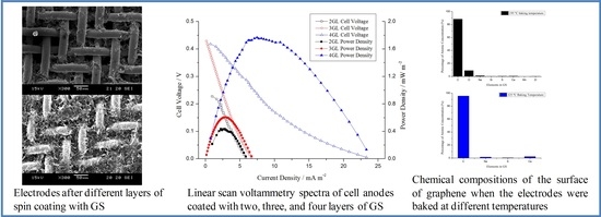
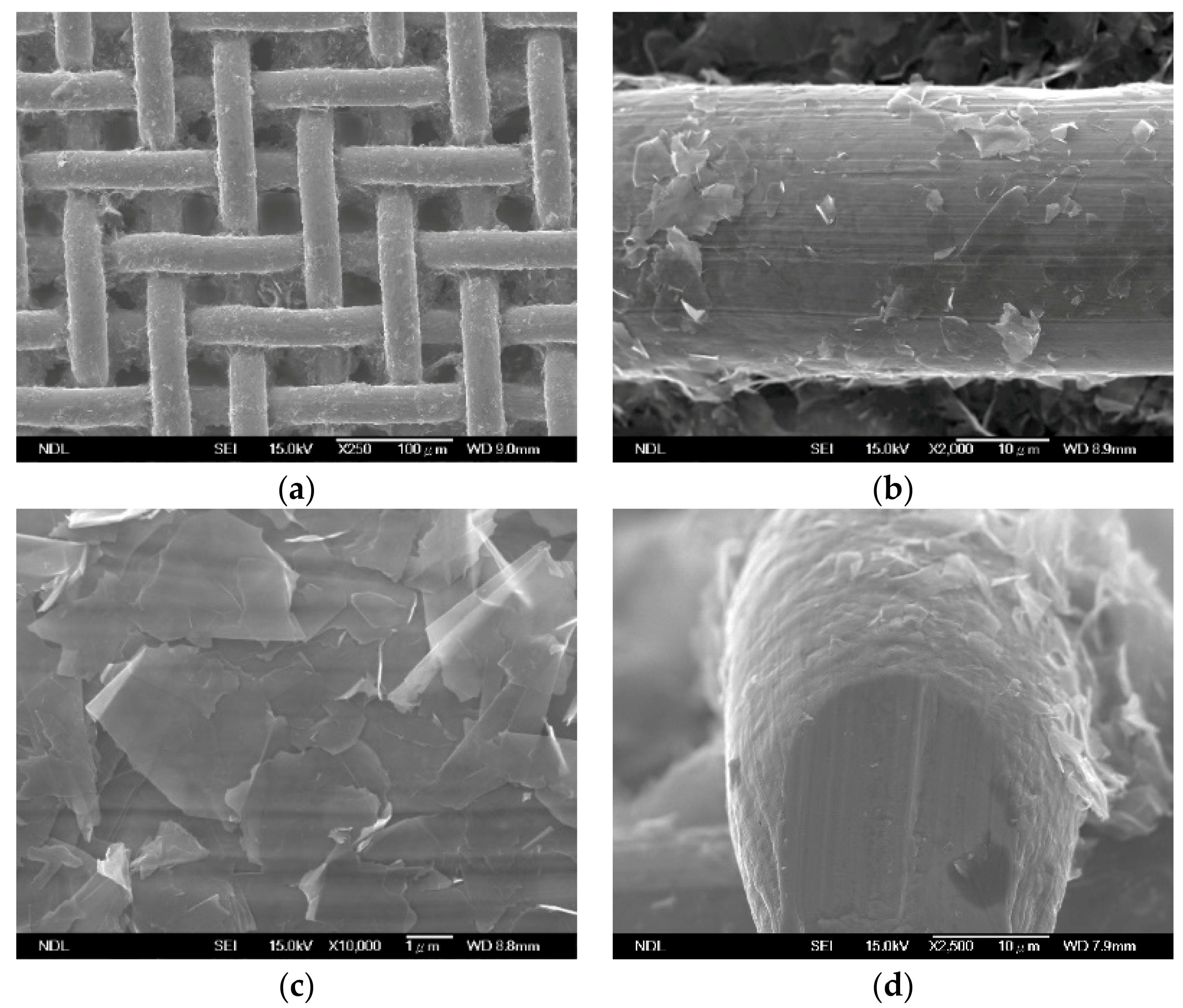
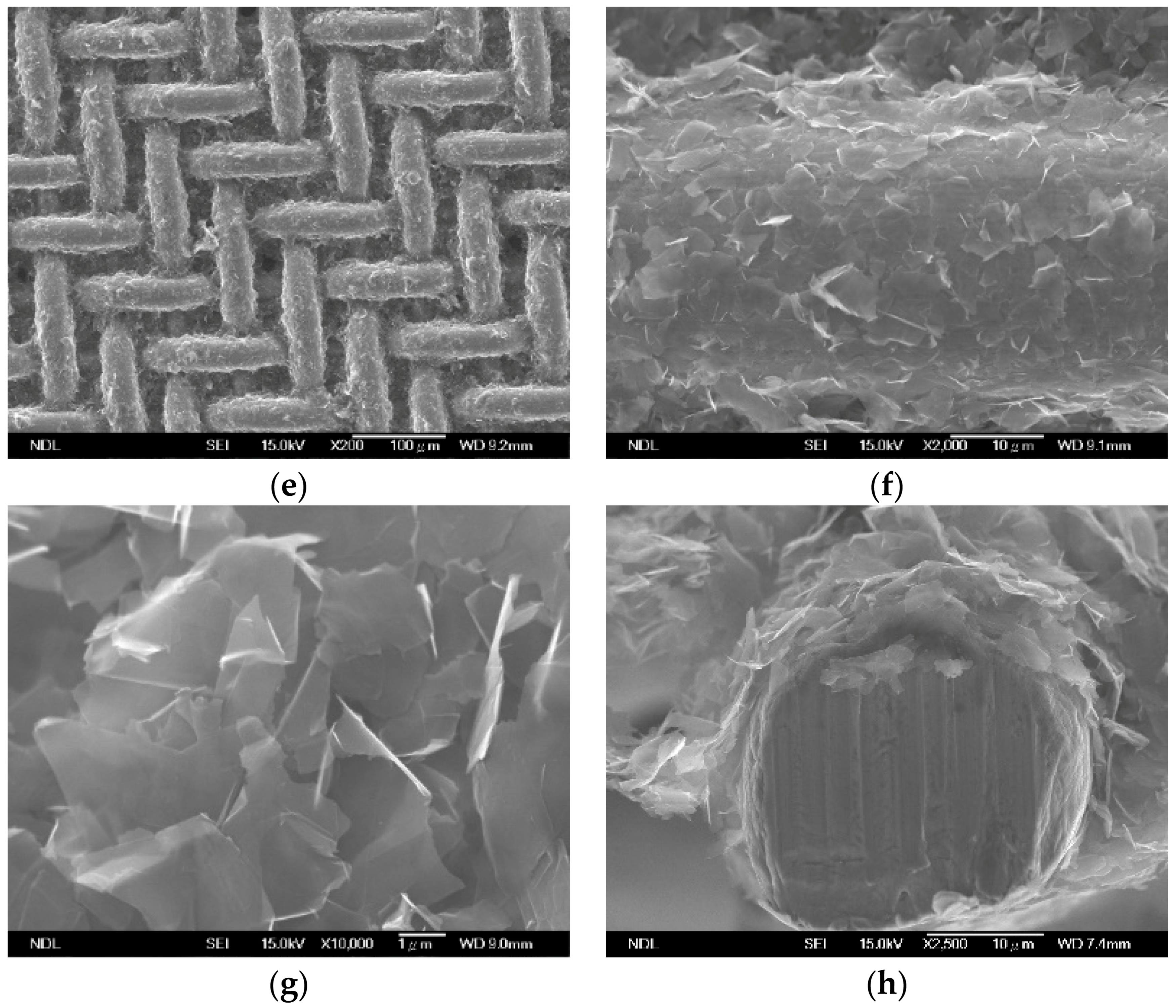
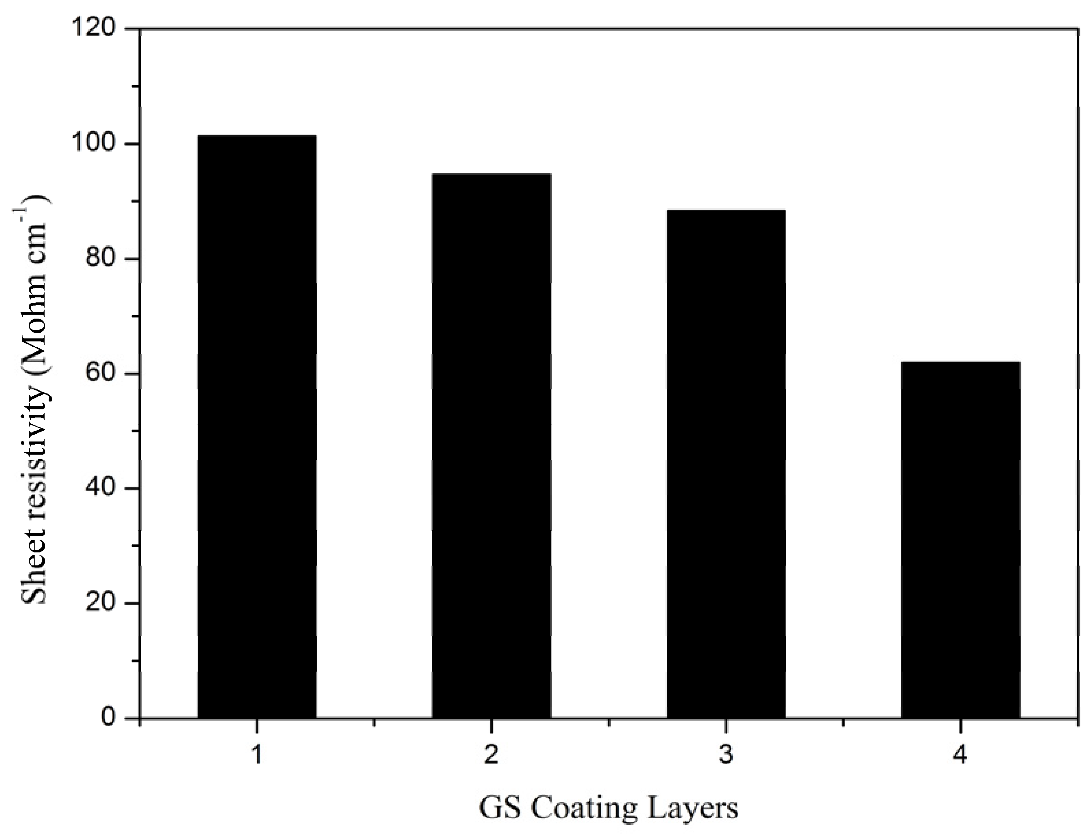
Figure 2 displays the surface of mesh electrodes after two layer (Figure 2a,d) and four layers (Figure 2e,h) of spin coating with graphene suspension (GS). Increasing the number of coating layers increased the amount of graphene adhered to the electrodes as well as the uniformity of the graphene. Figure 3 depicts the resistance of electrodes with 1–4 layers of GS coating. The electrode coated with four layers of GS demonstrated the optimal resistance of 62 MΩ cm−1. The result indicated that the increased amount of adhered graphene and the improved uniformity of GS coating due to an increase in GS coating layers enhanced the electrode conductivity.
3.2. Effect of Electrode Baking Temperature on MFC Performance
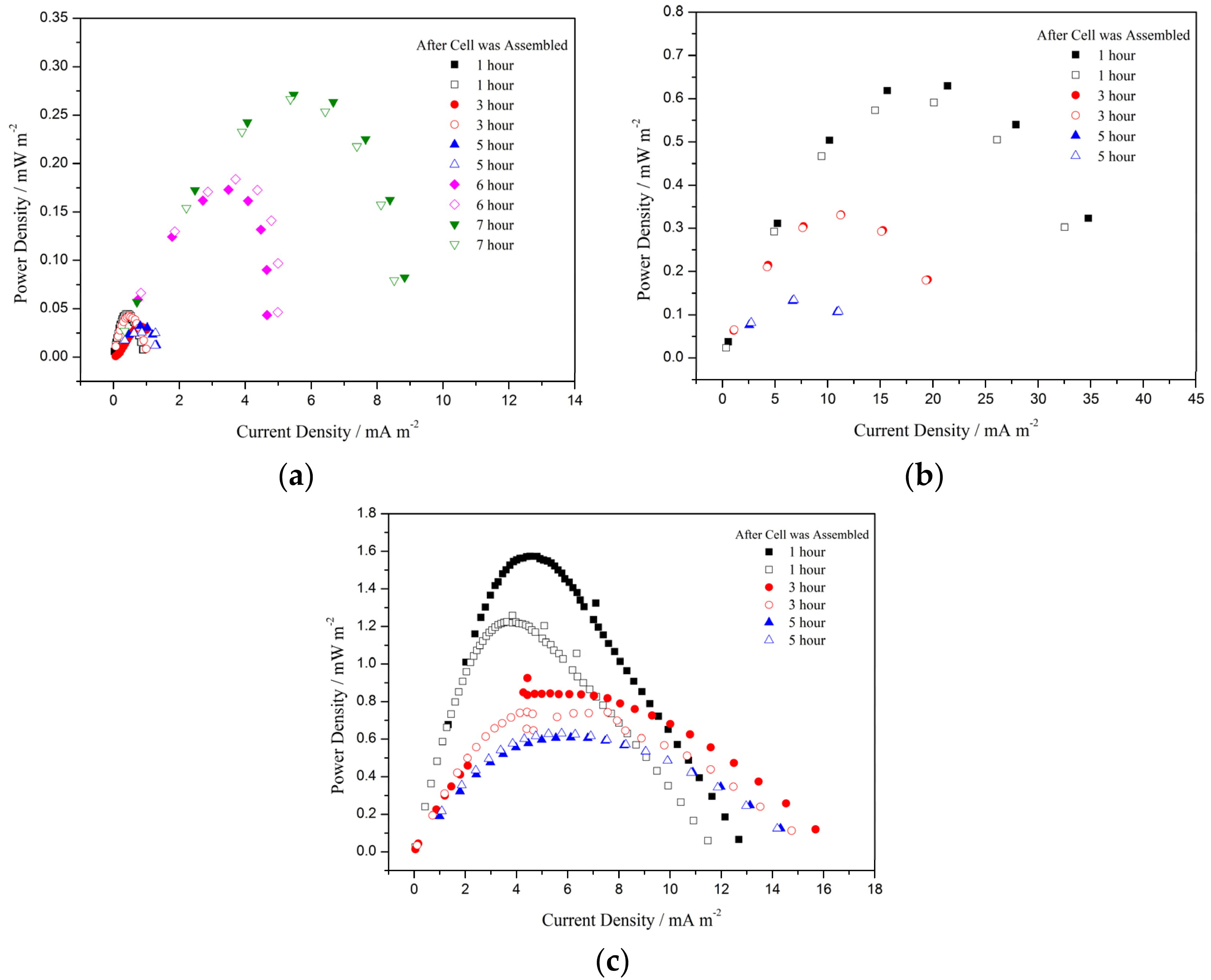
Commercial GS contains dispersants. After GS coating, the electrodes were baked at various temperatures to examine the effect of residual dispersants on microbial fuel cell (MFC) performance. Figure 4 provides the linear scan voltammetry (LSV) spectra of MFC electrodes baked at various temperatures. Specifically, baking temperatures of 195, 250, and 325 °C led to maximal power densities of 0.27, 0.62, and 1.57 mW m−2, respectively (Figure 3b,c and Figure 4a). After the MFC was assembled using electrodes spin coated with GS and dried at 195 °C, the cell performance notably improved 6 h after the assembly, but the maximum power density remained lower than those of the MFCs with electrodes dried at 250 and 325 °C. The aforementioned phenomenon did not occur when drying temperatures were 250 and 325 °C. At these two temperatures, the MFC power output first increased with time and then gradually decreased, finally reaching stability. Therefore, this study inferred that increasing the electrode drying temperature enhanced the decomposition of dispersants in the GS coating and improved the power density and cell stability.
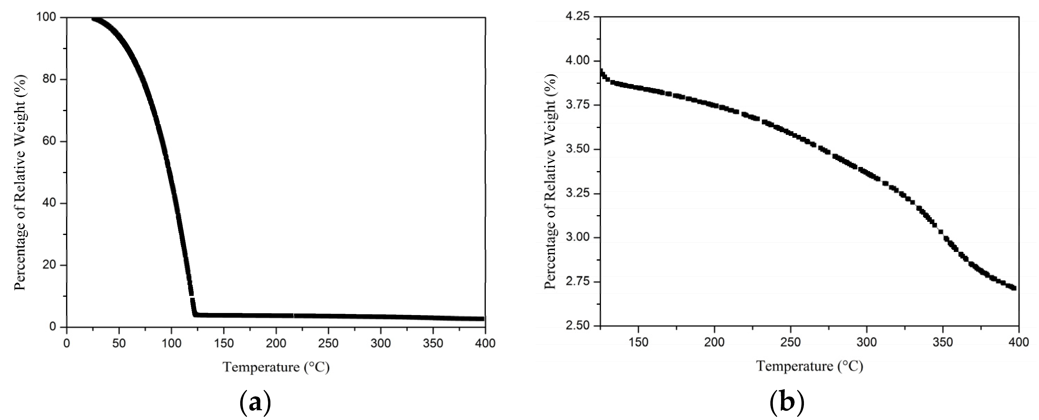
To further investigate the effect of baking temperature on graphene characteristics, this study explored the variations in the weight of GS coating and graphene surface composition under different temperatures using thermogravimetric analysis (TGA) and energy-dispersive X-ray spectroscopy (EDX). Figure 5a depicts the change in the weight percentage of the GS from room temperature to 400 °C. Because when the temperature exceeded 100 °C, the change in GS weight percentage was subtle, the weight change between 125 and 400 °C is separately displayed in Figure 5b. In the heating process, when the temperature was increased from room temperature to approximately 125 °C, the water content in GS evaporated rapidly, which led to a rapid decrease of the weight GS. When the temperature was higher than 125 °C, the weight of GS started to slowly decrease. The water in GS was expected to have evaporated completely when the temperature exceeded 130 °C, but when the temperature was increased from 130 to 300 °C, the variation in the weight of the GS was approximately 20%. This variation indicated that a considerable amount of dispersant was retained at 130 °C, and the small weight loss might be attributable to the decomposition of solid composition in GS. Thus, the result indicated that increasing the baking temperature of coated electrodes facilitated graphene purification.
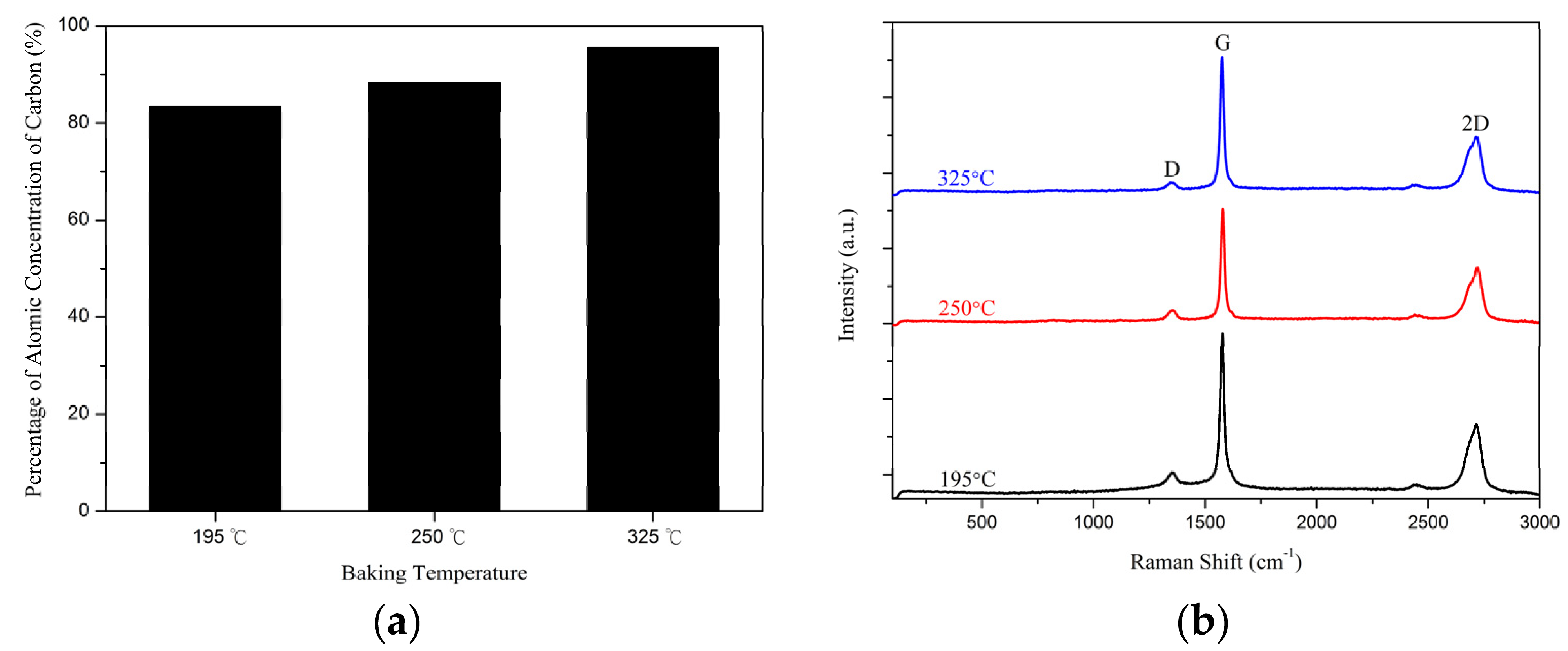
EDX (JSM-5600, Jeol Co., Tokyo, Japan) analysis and Raman spectroscopy (IHR550, Horiba Jobin Yvon, Kyoto, Japan) were used to evaluate the quality and layer stacking of graphene baked at different temperatures, as illustrated in Figure 6. EDX analysis of Figure 6a indicates that the percentage of the atomic concentration of carbon increased from 85% to 95% as the baking temperature increased from 195 to 325 °C. The proportion of carbon increased as the baking temperature increased. This result was illustrated through Raman spectroscopy and can be seen in Figure 6b. Raman spectroscopy is a reliable tool for evaluating the quality and layer stacking of graphene. The intensity ratio of D peak to G peak, I(D)/I(G), provides information regarding the level of disorder in terms of covalent modification of graphene. When the baking temperature increased from 195 to 325 °C, the intensity ratio of the D peak to G peak decreased from 0.13 to 0.07. An increase in the proportion of carbon on the surface of graphene is a result of the decrease in covalent bond characters. The results mean that the probability of adsorption between graphene surface and with other substances is reduced as the baking temperature increased. Furthermore, the intensity ratio of 2D peak to G peak, I(2D)/I(G), provides information regarding the layer stacking of graphene. In our study, the intensity ratio of 2D peak to G peak was similar and approximately 0.4. The graphene we used was multilayer, and the structure was not significantly affected by the baking temperature. According to the aforementioned results, an increase in the baking temperature of GS improved the quality of graphene and improved MFC performance. In the next two sections, the observation of biofilm formation and effect of the number of GS coating layers on MFC performance are explored using coated electrodes baked at 325 °C.
3.3. Biofilm Morphology
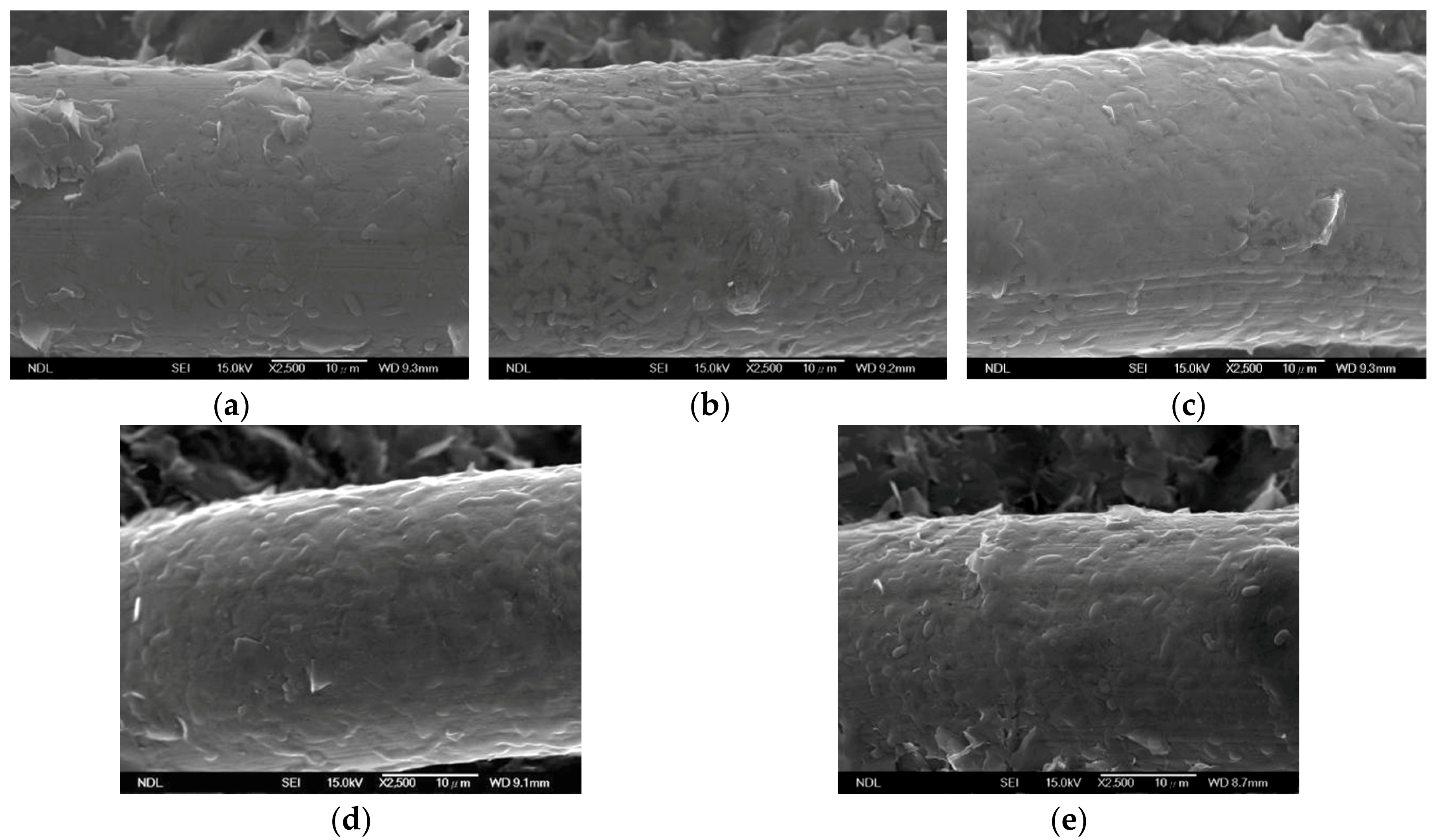
The biofilm morphology was characterized by SEM. Figure 7 shows the surface morphology of the anode coated with two layers of GS at various times after the cells were assembled. When the cell operating time was less than 3 h, the number of microorganisms attached to the anode surface increased as the operating time increased, as exhibited in Figure 7a,b. However, when the cell operating time was greater than 5 h, the number of microorganisms attached to the anode surface only slightly increased, as shown in Figure 7c–e. The biofilm formation time in the MFC system was approximately 3 h.
3.4. Effect of the Number of GS Coated Layers on MFC Performance
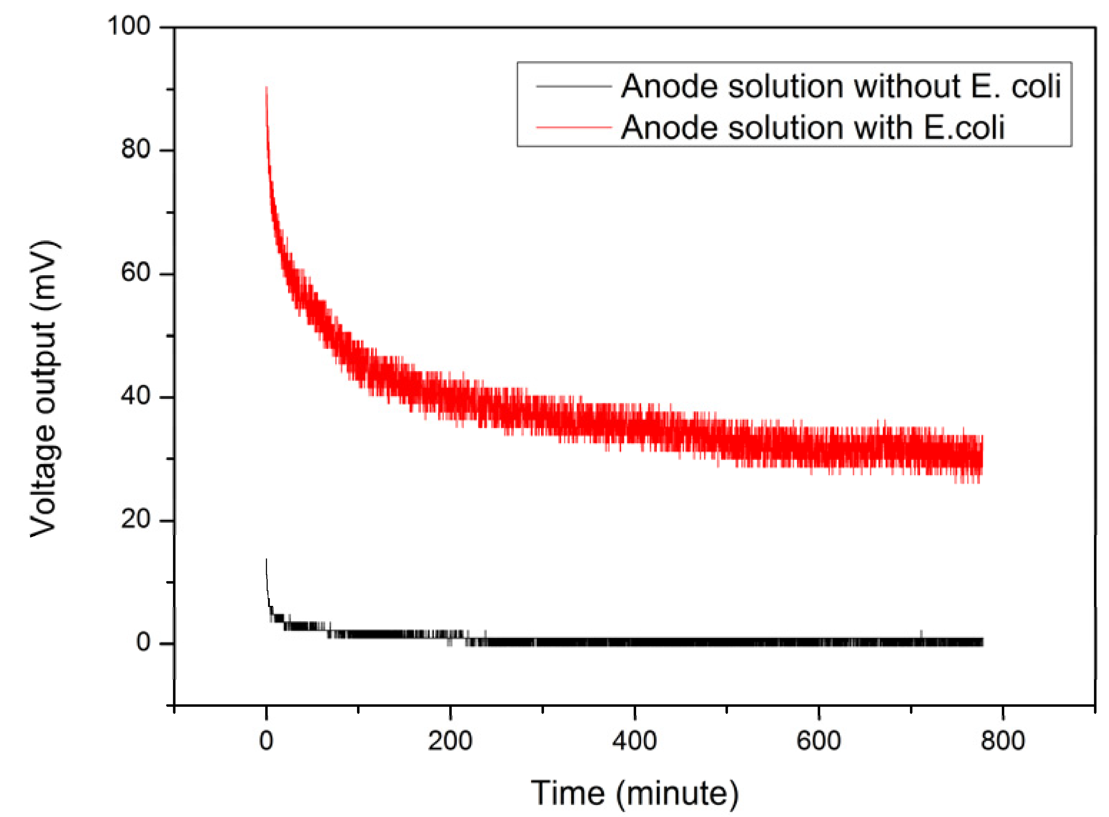
To investigate the effect of the number of GS coated layers on MFC performance, anodes were spin coated with 2–4 layers of GS and baked at 325 °C. The substrates for cathodes and anodes were identical; one layer of GS and polytetrafluoroethylene was spin coated on the surface as the catalyst and waterproofing layers, respectively. Notably, to ensure all the data were acquired when the cells were at a stable state, the output voltage variation over time was assessed after all the cells were assembled with the experimental electrodes. Figure 8 shows the voltage output from the SSM anode coated with two layers of GS a long period after the cells were assembled. The red line in the Figure 7 illustrates the result of adding E. coli to the anode tank, and the black line shows the result of not adding E. coli. We considered the MFC system to have reached a stable value when the output signal variation was less than 5% of its steady-state value. When the SSM anode was coated with two layers of GS, the MFC system was able to reach a stable state after the cell was assembled for 218 min, and the steady state value of the voltage output was approximately 40 mV. When E. coli was not added to the anode tank, the voltage output was approximately 0.7 mV, equivalent to noise. Thus, in the studied MFC system, the conversion of energy was through E. coli and occurred in a favorable experimental environment. In addition, the anodes coated with three and four layers of GS required 225 and 232 min for MFCs to reach a stable state, respectively. Increasing the thickness of graphene coated on electrode substrates only slightly affected MFCs’ stabilizing time. Moreover, the time required for the system to enter a steady state was similar to the biofilm formation time.
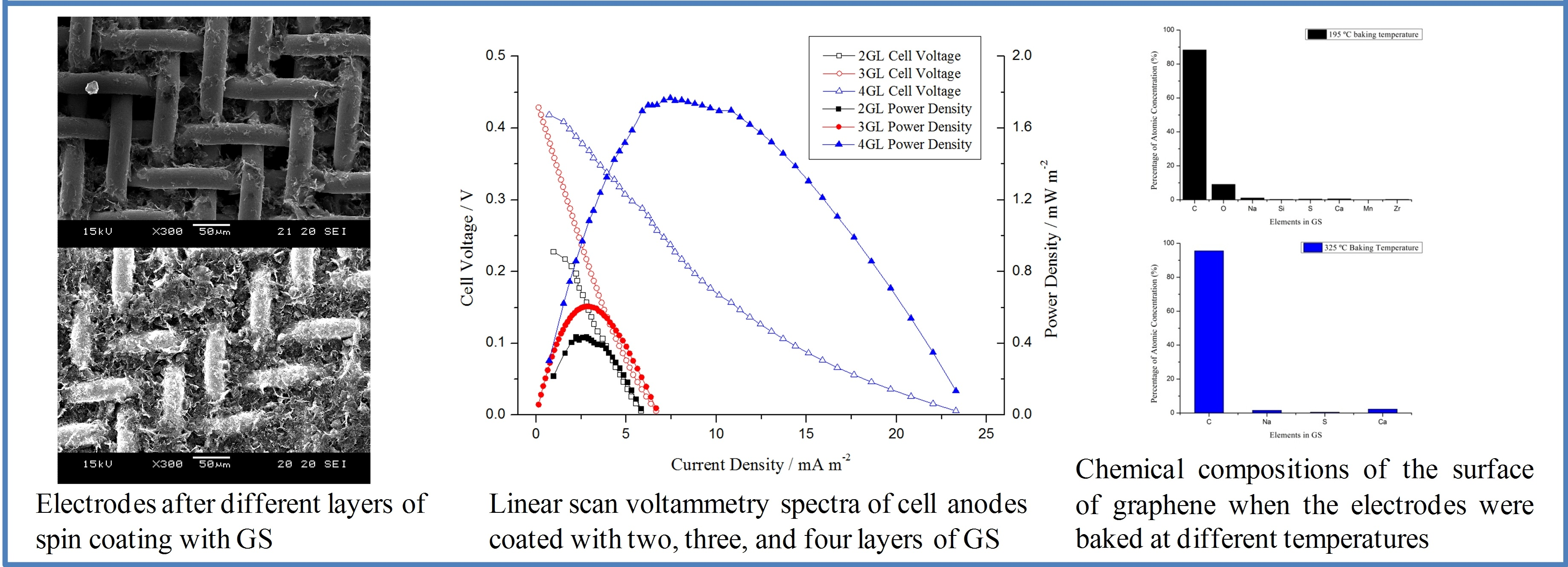
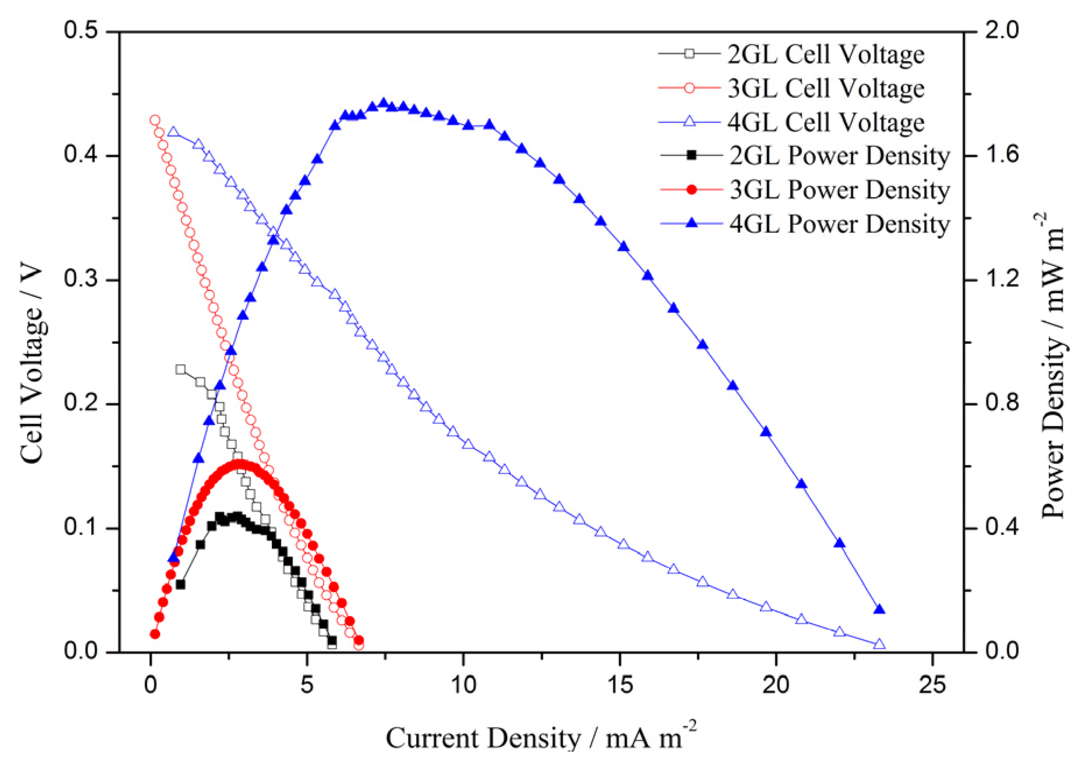
To ensure experimental precision, based on the evaluation results of MFCs, LSV measurement was conducted 5 h after the cells were assembled. In Figure 9, 2GL, 3GL, and 4GL are the LSV results of cell anodes coated with two, three, and four layers of GS, respectively. The open circuit voltage (OCV) of 2GL, 3GL, and 4GL were 0.23, 0.43, and 0.42 V, respectively, whereas the maximum power density of 2GL, 3GL, and 4GL were 0.44, 0.61, and 1.77 mW m−2, respectively. The maximum power density of the cell equipped with a four-layer graphene anode was approximately four times that of the cell equipped with a two-layer graphene anode. Increasing the number of spin coated layers improved the amount of graphene adhering to the surface of the stainless-steel mesh. Thus, the specific surface area and conductivity of the electrodes were effectively increased, resulting in improved MFC performance.
4. Conclusions
This paper proposes an innovative method for stainless steel mesh modification: using GS spin coating technology to control the number of coating layers and the adhesion amount of graphene on electrodes. Because commercial GS contained dispersants, a heating process was required for the thermodecomposition of the dispersants. To explore the effect of residual dispersants on graphene quality, this study investigated the variation in the weight of the GS coating, the surface compositions and defect of graphene under various temperatures through TGA, EDX analysis, and Raman spectroscopy. The results showed that when the baking temperature was higher than 325 °C, the weight change of the graphene coating was less than 1%, and the carbon proportion on the surface of graphene exceeded 95%. Moreover, an increase in the baking temperature resulted a decrease in covalent bond characters of graphene surface. This indicated that this temperature could effectively decompose the dispersants in graphene and reduce the amount of dispersant residue on the graphene surface, resulting in an increase in graphene activity.
After deciding the required drying temperature of commercial GS coating on stainless steel mesh electrodes, this study explored the effect of the number of GS spin coating layers on MFC performance. By observing the coating using scanning electron microscopy and measuring the resistance using four-point probes, the increase in the number of coating layers was proved to be effective in increasing the amount of graphene adhered to the electrodes and the conductivity of the electrodes. Furthermore, the results of LSV measurements proved that the maximum power density increased four-fold (from 0.44 to 1.77 mW m−2) when GS spin coating increased from two to four layers.
The proposed electrode modification method is simple in its process and substantially reduces graphene consumption in the coating process. Therefore, this method effectively reduces the cost of electrode modification. By controlling the number of GS spin coating layers and the drying temperature of electrodes, this study revealed the effect of the modification parameters on MFC performance and verified the feasibility of the proposed method. This method can be used to facilitate MFC development.
Author Contributions
Conceptualization, H.-Y.T. and W.-H.H.; Methodology, H.-Y.T. and W.-H.H.; Software, W.-H.H. and Y.-J.L.; Validation, W.-H.H. and Y.-J.L.; Formal Analysis, W.-H.H. and Y.-J.L.; Investigation, H.-Y.T. and W.-H.H.; Resources, H.-Y.T. and W.-H.H.; Data Curation, H.-Y.T. and W.-H.H.; Writing-Original Draft Preparation, W.-H.H.; Writing-Review & Editing, H.-Y.T.; Visualization, H.-Y.T. and W.-H.H.; Supervision, W.-H.H.; Project Administration, W.-H.H.; Funding Acquisition, H.-Y.T. and W.-H.H.
Funding
This research received no external funding.
Acknowledgments
The authors are grateful to National Nano Device Laboratories for helping SEM imaging.
Conflicts of Interest
The authors declare no conflict of interest.
References
- Lovley, D.R. Bug juice: Harvesting electricity with microorganisms. Nat. Rev. Microbiol. 2006, 4, 497–508. [Google Scholar] [CrossRef] [PubMed]
- Potter, M.C. Electrical effects accompanying the decomposition of organic compounds. Proc. R. Soc. Lond. B 1911, 84, 260–276. [Google Scholar] [CrossRef]
- Lin, C.W.; Wu, C.H.; Huang, W.T.; Tsai, S.L. Evaluation of different cell-immobilization strategies for simultaneous distillery wastewater treatment and electricity generation in microbial fuel cells. Fuel 2015, 144, 1–8. [Google Scholar] [CrossRef]
- Abbasi, U.; Jin, W.; Pervez, A.; Bhatti, Z.A.; Tariq, M.; Shaheen, S.; Iqbal, A.; Mahmood, Q. Anaerobic microbial fuel cell treating combined industrial wastewater: Correlation of electricity generation with pollutants. Bioresour. Technol. 2016, 200, 1–7. [Google Scholar] [CrossRef] [PubMed]
- Doherty, L.; Zhao, Y.; Zhao, X.; Wang, W. Nutrient and organics removal from swine slurry with simultaneous electricity generation in an alum sludge-based constructed wetland incorporating microbial fuel cell technology. Chem. Eng. J. 2015, 266, 74–81. [Google Scholar] [CrossRef]
- Min, B.; Logan, B.E. Continuous electricity generation from domestic wastewater and organic substrates in a flat plate microbial fuel cell. Environ. Sci. Technol. 2004, 38, 5809–5814. [Google Scholar] [CrossRef] [PubMed]
- Liu, H.; Ramnarayanan, R.; Logan, B.E. Production of electricity during wastewater treatment using a single chamber microbial fuel cell. Environ. Sci. Technol. 2004, 38, 2281–2285. [Google Scholar] [CrossRef] [PubMed]
- Zhang, Y.; Mo, G.; Li, X.; Zhang, W.; Zhang, J.; Ye, J.; Huang, X.; Yu, C. A graphene modified anode to improve the performance of microbial fuel cells. J. Power Sources 2011, 196, 5402–5407. [Google Scholar] [CrossRef]
- Hsu, W.H.; Tsai, H.Y.; Huang, Y.C. Characteristics of carbon nanotubes/graphene coatings on stainless steel meshes used as electrodes for air-cathode microbial fuel cells. J. Nanomater. 2017, 2017, 9875301. [Google Scholar] [CrossRef]
- Tsai, H.Y.; Hsu, W.H.; Huang, Y.C. Characteristics of carbon nanotube/graphene on carbon cloth as electrode for air-cathode microbial fuel cell. J. Nanomater. 2015, 2015, 686891. [Google Scholar] [CrossRef]
- Liu, J.; Feng, Y.; Wang, X.; Shi, X.; Yang, Q.; Lee, H.; Zhang, Z.; Ren, N. The use of double-sided cloth without diffusion layers as air-cathode in microbial fuel cells. J. Power Sources 2011, 196, 8409–8412. [Google Scholar] [CrossRef]
- Noori, Md.T.; Mukherjee, C.K.; Ghangrekar, M.M. Enhancing performance of microbial fuel cell by using graphene supported V2O5-nanorod catalytic cathode. Electrochim. Acta 2017, 228, 513–521. [Google Scholar] [CrossRef]
- Noori, Md.T.; Ghangrekar, M.M.; Mukherjee, C.K. V2O5 microflower decorated cathode for enhancing power generation in air-cathode microbial fuel cell treating fish market wastewater. Int. J. Hydrogen Energy 2016, 41, 3638–3645. [Google Scholar] [CrossRef]
- Liu, H.; Logan, B.E. Electricity generation using an air-cathode single chamber microbial fuel cell in the presence and absence of a proton exchange membrane. Environ. Sci. Technol. 2004, 38, 4040–4046. [Google Scholar] [CrossRef] [PubMed]
- Yang, S.; Jia, B.; Liu, H. Effects of the Pt loading side and cathode-biofilm on the performance of a membrane-less and single-chamber microbial fuel cell. Bioresour. Technol. 2009, 100, 1197–1202. [Google Scholar] [CrossRef] [PubMed]
- Cercado-Quezada, B.; Delia, M.L.; Bergel, A. Treatment of dairy wastes with a microbial anode formed from garden compost. J. Appl. Electrochem. 2010, 40, 225–232. [Google Scholar] [CrossRef] [Green Version]
- Menicucci, J.; Beyenal, H.; Marsili, E.; Veluchamy, R.A.; Demir, G.; Lewandowski, Z. Procedure for determining maximum sustainable power generated by microbial fuel cells. Environ. Sci. Technol. 2006, 40, 1062–1068. [Google Scholar] [CrossRef] [PubMed]
- Logan, B.E.; Murano, C.; Scott, K.; Gray, N.D.; Head, I.M. Electricity generation from cysteine in a microbial fuel cell. Water Res. 2005, 39, 942–952. [Google Scholar] [CrossRef] [PubMed]
- Cheng, S.; Liu, H.; Logan, B.E. Increased power generation in a continuous flow MFC with advective flow through the porous anode and reduced electrode spacing. Environ. Sci. Technol. 2006, 40, 2426–2432. [Google Scholar] [CrossRef] [PubMed]
- Wei, J.; Liang, P.; Huang, X. Recent progress in electrodes for microbial fuel cells. Bioresour. Technol. 2011, 102, 9335–9344. [Google Scholar] [CrossRef] [PubMed]
- Zhi, W.; Ge, Z.; He, Z.; Zhang, H. Methods for understanding microbial community structures and functions in microbial fuel cells. Bioresour. Technol. 2014, 171, 461–468. [Google Scholar] [CrossRef] [PubMed]
- Malvankar, N.S.; Lovley, D.R. Microbial nanowires: A new paradigm for biological electron transfer and bioelectronics. ChemSusChem 2012, 5, 1039–1046. [Google Scholar] [CrossRef] [PubMed]
- Schröder, U. Anodic electron transfer mechanisms in microbial fuel cells and their energy efficiency. Phys. Chem. Chem. Phys. 2007, 9, 2619–2629. [Google Scholar] [CrossRef] [PubMed]
- Cheng, S.; Logan, B.E. Ammonia treatment of carbon cloth anodes to enhance power generation of microbial fuel cells. Electrochem. Commun. 2007, 9, 492–496. [Google Scholar] [CrossRef]
- Hou, J.; Liu, Z.; Li, Y.; Yang, S.; Zhou, Y. A comparative study of graphene-coated stainless steel fiber felt and carbon cloth as anodes in MFCs. Bioprocess Biosyst. Eng. 2015, 38, 881–888. [Google Scholar] [CrossRef] [PubMed]
- Craig, S.; Harding, G.L.; Payling, R. Auger lineshape analysis of carbon bonding in sputtered metal-carbon thin films. Surf. Sci. 1983, 124, 591–601. [Google Scholar] [CrossRef]
- Gao, H.J.; Wang, X.; Yao, H.M.; Gorb, S.; Arzt, E. Mechanics of hierarchical adhesion structures of geckos. Mech. Mater. 2005, 37, 275–285. [Google Scholar] [CrossRef]
Figure 1.
Schematic (a) and cross-section (b) of the single-chamber microbial fuel cells (MFCs) used in the experiment.
Figure 1.
Schematic (a) and cross-section (b) of the single-chamber microbial fuel cells (MFCs) used in the experiment.

Figure 2.
Surface of stainless steel mesh electrodes after one layer (a–d) and four layers (e–h) of spin coating with graphene suspension (GS).
Figure 2.
Surface of stainless steel mesh electrodes after one layer (a–d) and four layers (e–h) of spin coating with graphene suspension (GS).


Figure 3.
Effect of GS coating on electrode resistance

Figure 4.
Current–power density curves of MFCs measured between 1 and 7 h after the cells were assembled; the electrodes were dried at temperatures of (a) 195, (b) 250, and (c) 325 °C.
Figure 4.
Current–power density curves of MFCs measured between 1 and 7 h after the cells were assembled; the electrodes were dried at temperatures of (a) 195, (b) 250, and (c) 325 °C.

Figure 5.
Thermogravimetric analysis (TGA) results: (a) variation in weight percentage of GS coating from room temperature to 400 °C; (b) subtle variation in weight percentage of GS coating at 125–400 °C.
Figure 5.
Thermogravimetric analysis (TGA) results: (a) variation in weight percentage of GS coating from room temperature to 400 °C; (b) subtle variation in weight percentage of GS coating at 125–400 °C.

Figure 6.
(a) X-ray spectroscopy (EDX) analysis and (b) Raman spectroscopy were employed to evaluate the quality and layer stacking of graphene baked at different temperatures.
Figure 6.
(a) X-ray spectroscopy (EDX) analysis and (b) Raman spectroscopy were employed to evaluate the quality and layer stacking of graphene baked at different temperatures.

Figure 7.
Surface morphology of the anode at (a) 1 h, (b) 2 h, (c) 3 h, (d) 5 h, and (e) 10 h after the cells were assembled.
Figure 7.
Surface morphology of the anode at (a) 1 h, (b) 2 h, (c) 3 h, (d) 5 h, and (e) 10 h after the cells were assembled.

Figure 8.
Effect of E. coli on the voltage output of the MFC system.

Figure 9.
Linear scan voltammetry (LSV) results of anodes coated with two to four layers of GS.

© 2018 by the authors. Licensee MDPI, Basel, Switzerland. This article is an open access article distributed under the terms and conditions of the Creative Commons Attribution (CC BY) license (http://creativecommons.org/licenses/by/4.0/).
Share and Cite
MDPI and ACS Style
Tsai, H.-Y.; Hsu, W.-H.; Liao, Y.-J. Effect of Electrode Coating with Graphene Suspension on Power Generation of Microbial Fuel Cells. Coatings 2018, 8, 243. https://doi.org/10.3390/coatings8070243
AMA Style
Tsai H-Y, Hsu W-H, Liao Y-J. Effect of Electrode Coating with Graphene Suspension on Power Generation of Microbial Fuel Cells. Coatings. 2018; 8(7):243. https://doi.org/10.3390/coatings8070243
Chicago/Turabian StyleTsai, Hung-Yin, Wei-Hsuan Hsu, and Yi-Jhu Liao. 2018. "Effect of Electrode Coating with Graphene Suspension on Power Generation of Microbial Fuel Cells" Coatings 8, no. 7: 243. https://doi.org/10.3390/coatings8070243
Note that from the first issue of 2016, this journal uses article numbers instead of page numbers. See further details here.