Influence of Sputtering Power of ZrB2 Target on Structure and Properties of Nanocomposite Zr-B-O Films

1
College of Physics and Materials Science, Tianjin Normal University, Tianjin 300387, China
2
Tianjin International Joint Research Centre of Surface Technology for Energy Storage Materials, Tianjin Normal University, Tianjin 300387, China
*
Authors to whom correspondence should be addressed.
Coatings 2019, 9(10), 611; https://doi.org/10.3390/coatings9100611
Submission received: 31 August 2019
/
Revised: 20 September 2019
/
Accepted: 23 September 2019
/
Published: 25 September 2019
(This article belongs to the Special Issue Advances in Multi-Target Physical Vapor Deposition Techniques)
Abstract
:The nanocomposite Zr-B-O films based on ZrB2 and ZrO2 are successfully deposited on Si (100) and stainless-steel substrates via a multi-target magnetron co-sputtering system. The influence of the sputtering power of ZrB2 target on sample structure and performance was analyzed by scanning electron microscope (SEM), transmission electron microscope (TEM), X-ray diffraction (XRD), and X-ray photoelectron spectrometer (XPS). Nano scratch tests were conducted to measure the films’ mechanical properties. Their oxidation resistance in an aerobic environment was tested by high-temperature oxidation in a muffle furnace. Corrosion behaviors of the Zr-B-O films were evaluated by potentiodynamic polarization and electrochemical impedance spectroscopy. It shows that the interior of the composite films has a high degree of non-crystallization. The maximum hardness (26.76 GPa) and corresponding elastic modulus (268.05 Gpa) of the film were obtained at the sputtering power of 120 W. The hardest film also shows the better oxidation resistance with a mass change of around 0.1% before and after oxidation under 1000 °C for 1 h. However, the corrosion resistance of Zr-B-O nanocomposite films is negatively correlated with the power of ZrB2, which is related to the microstructure of the composite film.
1. Introduction
In recent years, there are increasingly higher requirements for materials used in engineering components, processing tools, and other application fields, especially on mechanical properties, friction and wear properties, high-temperature resistance, and corrosion resistance [1,2]. As the protective coating of tools, hard nanocomposite films need to be modified to improve their comprehensive performances, which can extend the service life of tools in industrial applications and prevent rapid failure in extreme harsh environments [3,4,5,6,7,8,9]. ZrB2, as a typical of transition metal diboride, has a simple hexagonal crystal structure. Its inherent crystal structure and firm combination of B–B covalent bonds determine that ZrB2 has good chemical stability and excellent physical properties, including high elastic modulus, high hardness, and a moderate thermal expansion coefficient [10,11]. However, the high concentration of B–B covalent bonds and the low self-diffusion coefficient of ZrB2 leads to the decrease of compactness [12]. In addition, ZrB2 has the drawbacks of low fracture toughness, low mechanical reliability, and unreliable high-temperature properties, which also need to be improved for better application [13,14,15].
Different from boride, ZrO2 is a kind of high-temperature resistant material. Due to its good thermal stability, high-temperature strength, and corrosion resistance, ZrO2 has been widely used for nanomaterials, multilayer composite materials, and microelectronic materials [16,17,18]. However, pure ZrO2 needs to be stabilized by introducing other materials, because the volume of ZrO2 will change due to the phase transition. It is hopeful that high mechanical strength, excellent oxidation resistance, and good corrosion resistance can all be obtained by doping oxide to boride. Many studies have already combined them with other materials to prepare composite materials with better properties by the hot-pressing method [19,20,21,22,23,24]. The hot-pressing method can easily make the material phase change, leading to an increase of porosity and grain size. The magnetron sputtering method can make up the defects caused by phase transition, and the prepared films are usually uniform, dense, and have good adhesion to the substrate. Therefore, the nanocomposite films with the desired structure and performance can be produced by directly mixing ZrB2 and ZrO2 using the magnetron co-sputtering method.
In this work, the Zr-B-O nanocomposite films are deposited on Si (100) and stainless-steel substrate by sputtering ZrB2 and ZrO2 targets using multi-target magnetron co-sputtering. This method can accurately control deposition parameters and realize the combination of ZrB2 and ZrO2 at low temperature. As the ZrO2 target is more fragile than the ZrB2 target, we choose to change the sputtering power of ZrB2 target to control the deposition rate so as to obtain the films with a different thickness and composition. The main purpose of this work is to investigate the effect of the sputtering power of the ZrB2 target on the microstructure, mechanical properties, oxidation resistance, and corrosion resistance of Zr-B-O films. Thus, an optimum composition is expected to yield superior comprehensive properties.
2. Materials and Methods
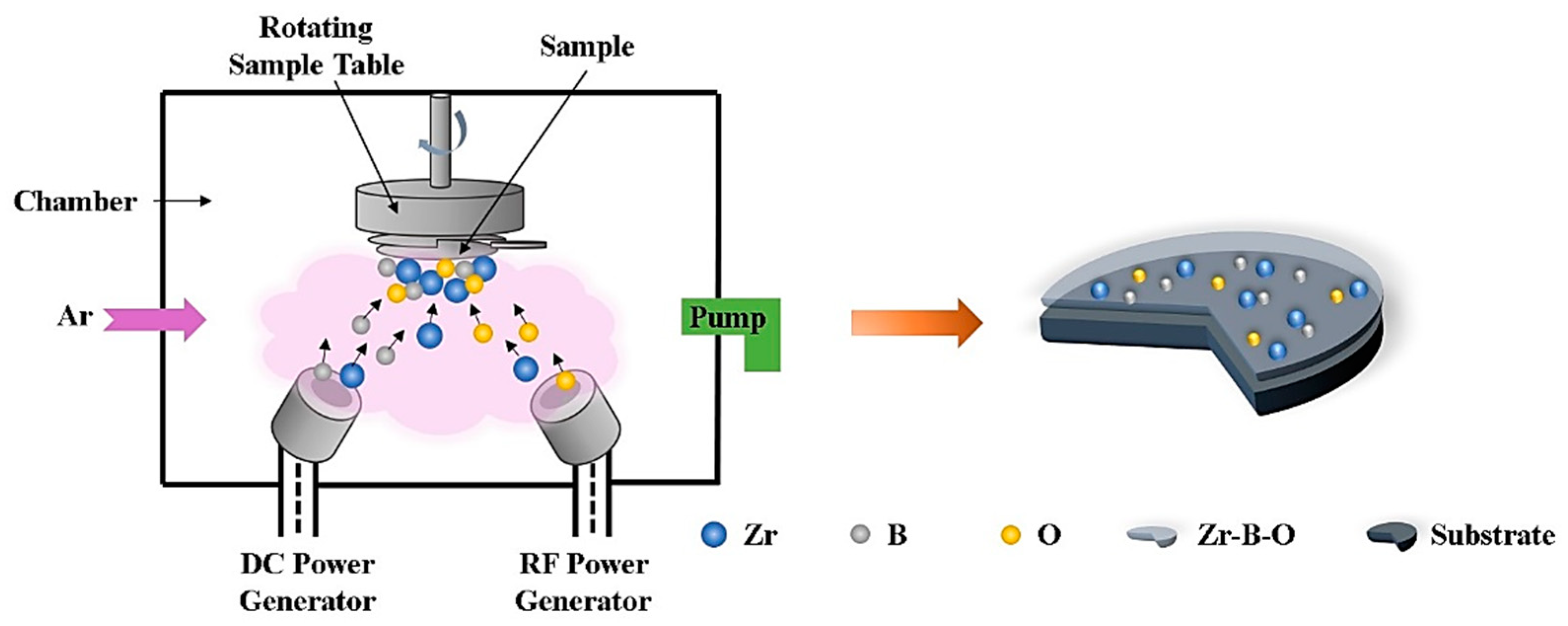
Zr-B-O nanocomposite films at different sputtering power of ZrB2 were deposited by a computer-controlled magnetron sputtering system. High purity targets of ZrB2 (99.99%, diameter 50.8 mm, thickness 4 mm, HZAM, Beijing, China) and ZrO2 (99.99%, diameter 50.8 mm, thickness 4 mm, HZAM, Beijing, China) were respectively connected to direct current-pulsed (DC) and radio frequency (RF) source sputter guns, which were fixed at both sides of chamber. The heated sample holder which was 7 cm away from the two co-sputtering targets was placed on the top of the chamber. Its rotation speed was 1 r/min. Silicon wafers (100) and stainless-steel substrates were cleaned in an ultrasonic agitator in acetone (99.7%) and ethanol (99.7%) ordinally for 15 min and then dried using compressed air before being mounted on a rotatable substrate holder. The chamber was first vacuumed to a base pressure lower than 4.5 × 10⁻⁴ Pa, and then the high purity argon (99.999%) plasma was introduced into the chamber to clean substrates for 15 min at −400 V bias voltages and a pressure of 5.0 Pa prior to the deposition of nanocomposite films. Impurities and adsorbed gases on the surface of substrates were removed by low bias voltage. The preparation of Zr-B-O nanocomposite films was carried out under a work pressure of 0.4 Pa and an Ar gas flow of 40 sccm. The ZrO2 target was deposited at a fixed power of 80 W, while the ZrB2 target was deposited at different powers from 80 to 120 W at room temperature with −80 V bias voltage. The deposition time was 3 h, and the final thickness of the films was about 600–800 nm. The experimental schematic diagram of this study is shown in Figure 1.
A scanning electron microscope (SEM, SU8010, Hitachi, Tokyo, Japan) was used to survey the thickness and the fracture surface morphology of the Zr-B-O film. Meanwhile, the sectioned surface morphology of the nanocomposite films was observed by a high-resolution transmission electron microscope (HRTEM, JEM-2100F, JEOL, Tokyo, Japan). Wide angle X-ray diffraction (XRD, D8A, Bruker, Karlsruhe, Germany) with Cu-Kα (40 kV, 20 mA, λ = 1.54056 Å) radiation was used to determine the films’ microstructure and crystalline nature. An X-ray photoelectron spectrometer (XPS, PHI5000VersaProbe, Ulvac-Phi, Chigasaki, Japan) was used to characterize the chemical composition and chemical bonds. The contaminated C1s (284.6 eV) was used as a reference for correcting charge shift. Furthermore, these XPS spectra were fitted by XPSPEAK software (version 4.1), and Shirley background was chosen for background calculation of these XPS spectra.
The mechanical properties of nanocomposite films were studied by the instrumented indentation test using a nano scratch tester (NST, STEP6, Anton Paar, Graz, Austria). The Oliver-Pharr method was applied to measure the hardness and elastic modulus of films [25,26]. The maximum indention depth for all samples was fixed at about 10% of the films’ thickness in order to minimize the substrate effects. Progressive linear scratch tests, with a 50 μm radius Rockwell diamond spherical indenter, were performed to characterize the adhesion property of materials. An oxidation test was carried out in a muffle furnace (LFM1200C, CPI, Hefei, China) to investigate the effect of sputtering power on oxidation resistance of films. Samples were heated for half an hour from room temperature to the desired annealing temperatures (650, 750, 850 and 950 °C), and kept at these temperatures for 1 h. Then the samples were naturally cooled to room temperature in air. The samples were weighed using an electronic balance (XSE105, 0.01 mg, METTLER TOLEDO, Zurich, Switzerland) and the mass change was calculated using the following formula:
where ΔM is the mass change, M is the mass after annealing (in grams) and M0 is the mass before heating of samples, respectively.
Electrochemical impedance spectroscopy (EIS) and potentiodynamic polarization were measured by an electrochemical workstation (PARSTAT 2273, Princeton Applied Research, San Diego, CA, USA) at room temperature in a 3.5 wt.% NaCl aqueous solution, and the corrosion behavior of the samples was evaluated. A classical three electrode system was carried out, in which samples with stainless-steel substrates were used as the working electrode (exposed area 1 cm2), a platinum net and a saturated calomel electrode (SCE) served as auxiliary electrode and reference electrode, respectively. EIS experiments were conducted at open circuit potential with an AC amplitude of 0.01 V and a frequency range of 0.1 MHz to 0.01 Hz. Potentiodynamic polarization experiments were operated at a scan rate of 0.01 V/s.
3. Results and Discussion
3.1. Microstructures and Mechanical Properties
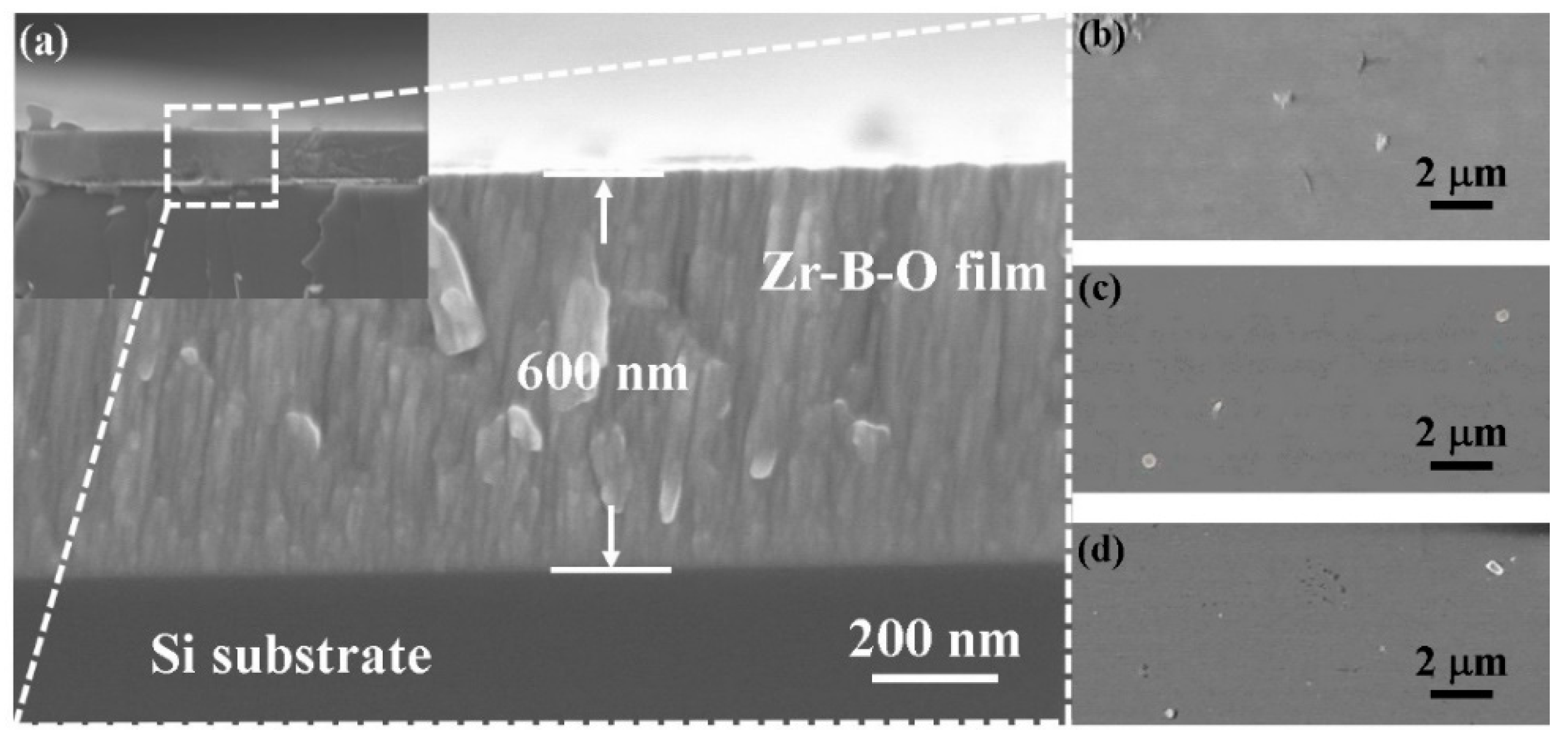
Figure 2a shows a fractured cross-sectional SEM image of the Zr-B-O nanocomposite film deposited at 80 W sputtering power of ZrB2 at room temperature. Apparently, the Zr-B-O nanocomposite film was successfully synthesized on Si (100) substrate. As can be seen from the image, the nanocomposite film shows a fine-grained microstructure character for magnetron sputtered boride film [27]. The thickness of the film with 80 W power of ZrB2 is approximately 600 nm resulting from a deposition rate of about 3.85 nm·min−1. In addition, it should be noted that during the deposition process, high-energy particles, and energetic ions bombard the newly formed film, leading to the attenuation of film thickness [28]. In order to remove the influence of different film thicknesses on the experimental results, we keep the thickness of Zr-B-O nanocomposite films at 600–800 nm under different sputtering powers of ZrB2 target. Simultaneously, top view SEM images of ZrO2, ZrB2, and Zr-B-O films were compared in Figure 2b–d. It can be clearly seen that these films prepared by magnetron co-sputtering have smooth surfaces, fewer defects, and good compactness. It would be more conducive to deterring outside destruction.
The X-ray diffraction patterns of a monolayer ZrB2 film and a monolayer ZrO2 film deposited on Si (100) substrates are shown in Figure 3a. The ZrB2 and ZrO2 targets were respectively sputtered in DC mode and RF mode with the power of 80 W during the deposition process. Clearly, the ZrB2 monolayer has a main peak at (001) and a sub-peak at (101). This indicates that the sample has a hexagonal symmetrical structure with alternating Zr and B atomic layers. ZrO2 exhibits the low-temperature monoclinic phase, and appears mixed orientation at (200) and (002) diffraction peaks. Figure 3b depicts the XRD diffractograms of Zr-B-O nanocomposite films with different powers of ZrB2. With the power increasing from 80 to 120 W, no obvious diffraction peak corresponding to (001) and (101) crystal plane of ZrB2 is found. Meanwhile, the (111) crystal orientation of monoclinic ZrO2 at about 31° is not obvious. These samples are almost in an amorphous state and some sub-crystals are formed inside, which causes the films densification in the interface. Compared with monolayer films, sputtering two targets simultaneously can inhibit their crystallinities to some extent. Because the two stages of atom collision cascade and rapid relaxation in the coating process will cause the loss of energy, which is conducive to the formation of amorphous structure, as illustrated in Figure 1 [29].
Figure 4a exhibits high-resolution XPS spectra of Zr3d for the Zr-B-O nanocomposite films at 80 W sputtering power of ZrB2 target. The narrow spectrum of Zr3d is split into two strong peaks, Zr 3d5/2, and Zr 3d3/2, and the positions of these two peaks are separated by about 2.32 eV. The Zr 3d5/2 could be assigned to two sub-peaks: ZrB2 (178.6 eV) and ZrO2 (183.3 eV); whereas the Zr 3d3/2 is composed of another two sub-peaks: ZrB2 (180.9 eV) and ZrO2 (186.6 eV) [30,31]. Based on previous studies, the binding energy values of B1s in Figure 4b correspond to the ZrB2 compounds and simple substance B, and the boron oxides is not observed to correspond to higher binding energy (193.3 eV) [30]. It can be seen that the 3d5/2 and 3d3/2 sub-peaks of ZrB2 are much wider and more intensive than that of ZrO2 in Figure 4a. Thus, Zr and B atoms mainly exist in the Zr-B bond in the composite films.
The variations of hardness and elastic modulus of Zr-B-O nanocomposite films with different sputtering powers of ZrB2 target and the fixed sputtering power of ZrO2 target at 80 W are described in Figure 5, as well as the hardness and elastic modulus of ZrB2 and ZrO2 monolayer films. The hardness value of nanocomposite films increases with the increasing sputtering power of the ZrB2 target. However, the elastic modulus of composite films basically maintains invariable or even decreases, exhibiting the opposite trend to that of hardness. The maximum hardness value of Zr-B-O nanocomposite films reaches 26.76 GPa when the sputtering power of ZrB2 target is 120 W and its corresponding elastic modulus is 268.05 Gpa, which are much higher than ZrB2 and ZrO2 monolayer films. This is because ZrB2, with its hexagonal crystal structure, exhibits highly anisotropic properties [32]. The hardness of (001) plane of ZrB2 is much higher than that of (100) plane [33]. The composite films prepared by adding soft phase, ZrO2, have the orientation of (001) plane of ZrB2, which helps the film maintain a high hardness and avoid being too brittle. Besides, when increasing the sputtering power of ZrB2 target, the deposition rate of ZrB2 was accelerated by the higher sputtering energy. Therefore, the relative content of ZrB2 increased, which shortened the distance of ZrB2 sub-grains and increased the size of crystallization of ZrB2 grains.
Figure 6 exhibits indentation morphology and the critical fracture load of ZrB2 monolayer and Zr-B-O nanocomposite films. Nano scratch tests were performed on the samples surface with a linearly increased load. In these tests, the maximum load was set to 5 N. These films scratches were observed by feedback of friction signal. The load corresponding to an abrupt increase in the friction signal is the critical fracture load (Lc) of the sample. Therefore, critical fracture load can indirectly characterize the adhesion capacity or fracture resistance of film. Beyond that, other factors such as hardness, plastic recovery, and internal stress also affect the fracture resistance of films. For the ZrB2 monolayer shown in Figure 6, when the load of indenter rises to 2.58 N at 1.03 mm, the friction curve appears to steeply increase, indicating that the film starts to fall off the substrate. Similarly, the critical fracture loads of the Zr-B-O composite film with 80 and 120 W power of ZrB2 target are 2.83 and 2.98 N respectively under the same test conditions. They are all higher than that of the ZrB2 monolayer. The working mode of magnetron sputtering produced good adhesion of film to substrate. Further, the atomic mixture between the film adding ZrO2 and Si (100) substrate is more favorable to promote the critical fracture load. The composite film prepared by 120 W power of ZrB2 has higher critical load because of its higher content of ZrB2 hard phase. According to the surface morphology of each sample and the friction value at the beginning of the scratch test, the composite film surface can be very smooth and flat by controlling the magnetron sputtering method under appropriate parameters. Almost no defects were observed on the surface. Such a dense surface is more conducive to resist outside damage and peel off from substrate.
3.2. Oxidation Resistance Properties
In order to observe the oxidation of thin films at different temperatures with different sputtering powers, many attempts have been made. It is found that the mass loss of composite films below 650 °C can be influenced by the evaporation of water vapor and impurities on film surfaces. Hence the observation of oxidation resistance of the samples was chosen at a temperature range of 650 to 950 °C. Figure 7a shows the fitting curves of oxidation-mass change of Zr-B-O composite films (different power of ZrB2) annealed from 650 to 950 °C for 1 h. Clearly, the mass of all samples increased from 650 °C. At the same testing temperature, the greater the sputtering power, the greater the mass change. On the other side, the films quality changes more with the rise of temperature. As can be seen from the diagram, the Zr-B-O nanocomposite films which were sputtered at 120 W of ZrB2 target are more stable with oxidation temperature rising. By observing samples’ surfaces, the films become loose from 850 °C. In general, the mass changes of nanocomposite films before and after heat treatment are about 0.1% and all the nanocomposite films do not fall off obviously from the silicon wafer. Different from nanocomposite films, the ZrB2 monolayer film at 80 W sputtering power appears to be partially detached after 850 °C oxidation. The addition of ZrO2 as a soft phase can effectively reduce the oxidation-mass gain. From earlier research [34], ZrB2 can be oxidized to form a layer of vitreous material containing B2O3 under 1100 °C and then hinder further oxidation. It can be concluded that the Zr-B ionic bonds are broken at high temperature, and the external O atoms penetrate into the film and form ZrO2 with Zr atoms, while the B atoms transform to B2O3. The specific oxidation reaction is as follows:
That is the reason why the nanocomposite films have mass gain at high temperature. Next, the addition of ZrO2 in ZrB2 could well control the size of grain in the films. The dense structure of amorphous inside the composite films has fewer defects, which can be conducive to preventing the invasion of oxygen atoms on the whole. For another, the composite film with 80 W power of ZrB2 has more mass change perhaps because of the higher relative content of ZrO2. The original O atoms in the film are mixed into the sub-crystal structure of ZrB2, which is easier to destroy the original structure in the oxidation process.
The XRD patterns of Zr-B-O composite films (120 W power of ZrB2 target) annealed from 650 to 950 °C for 1 h are given in Figure 7b. Starting from 750 °C, the internal transition of the film is from amorphous to crystalline. ZrB2 is in a completely amorphous state which the (001) and (101) crystal orientation are inhibited as temperature rises. Besides, the appearance of m-ZrO2 (−111), m-ZrO2 (200), and m-ZrO2 (111) crystal plane indicates that the growth of low temperature monoclinic phase of ZrO2 is promoted. Furthermore, three diffraction peaks of high-temperature tetragonal phase of ZrO2 are identified from 750 to 950 °C, corresponding to (011), (112), and (121) planes, respectively. The mixed texture of two phases in the films from 750 °C is consistent with references [35,36]. The stable and dense oxide layer formed after oxidation is also detected as B2O3, preventing O atoms from further entering under 1000 °C. On the other hand, the grains’ growth and phase transition will bring about a certain amount of volume change, leading to nanocomposite films fracture at the critical point of 1000 °C and peeling off from the substrates.
By observing the oxidation of the surface of films under different temperatures, the film at 120 W sputtering power of ZrB2 target under 850 °C oxidation was selected to study the microstructure changes of Zr-B-O nanocomposite film because it began to fall off after oxidation. As we can see in Figure 8a, the blurred selected area electron diffraction (SAED) patterns along with the amorphous-featured halo indicate poor crystallinity of the composite film. Two bright rings and a diffuse halo ring correspond to ZrB2 (101), m-ZrO2 (111), and ZrB2 (001). Figure 8b shows the TEM diffraction pattern of the sample at low magnification. It is obvious that the microstructure of Zr-B-O film is characterized as a nanocomposite structure with ZrO2 in the dark contrast surrounded by ZrB2 in the bright contrast. Due to the thick amorphous interface, the whole film has a dense structure. Even though the oxide layer is constantly inwardly expanding, the amorphous effect is that it absorbs more energy and there is a crystal transition process that dissipates a lot of heat. The grain size does not change too much in a short time.
After high-temperature oxidation, the typical polycrystalline structure of the film is shown in Figure 8c. The sharp diffraction rings can be assigned to m-ZrO2 (−111), m-ZrO2 (111), m-ZrO2 (200), and t-ZrO2 (112). These crystallites exhibit various growth orientations, perhaps because the ZrB2 has completely turned into amorphous interfacial phase. The thick amorphous interface could not coordinate the misorientations between the ZrO2 crystallites, which led to the random growth orientations of the ZrO2 crystallites [37,38]. What’s more, it can be observed from elemental mapping in Figure 8d that most of the color represented by oxygen element is concentrated in the top layer of the film. The deeper the film is, the lighter the film is oxidized. It is further proved that the dense amorphous structure effectively prevents the further oxidation of outside oxygen atoms.
3.3. Corrosion Resistance Properties
Figure 9 depicts the potentiodynamic polarization curves of the Zr-B-O nanocomposite films in 3.5 wt.% NaCl solution. For comparison, the stainless-steel substrate and ZrB2 monolayer were also tested. Meanwhile, the corrosion current densities (icorr) obtained by fitting polarization curves in Figure 9 are listed in Table 1. The data clearly reveals that after the addition of ZrO2, the icorr decreases by one order of magnitude from 2.9057 × 10⁻⁶ A·cm−2 of stainless-steel substrate to 4.5310 × 10⁻⁷ A·cm−2 of the Zr-B-O nanocomposite film with 80 W sputtering power of ZrB2 target. This indicates that the composite films doped with ZrO2 could greatly improve the corrosion resistance of the substrate as a whole. In combination with Figure 9, the icorr of the polarization curves gradually decreases with the reduction of sputtering power of ZrB2, indicating that the corrosion resistance of Zr-B-O nanocomposite films are slightly strengthened with the increased the power of ZrB2. It can also be seen from the polarization curves that the films surfaces are smooth and compact, because ZrO2 has changed the crystal structure of the ZrB2 monolayer after mixing. The corrosion resistance of amorphous composite films is effectively improved by reason that there are no defects such as grain boundary [39,40]. These conclusions will be further confirmed by the following EIS analysis.
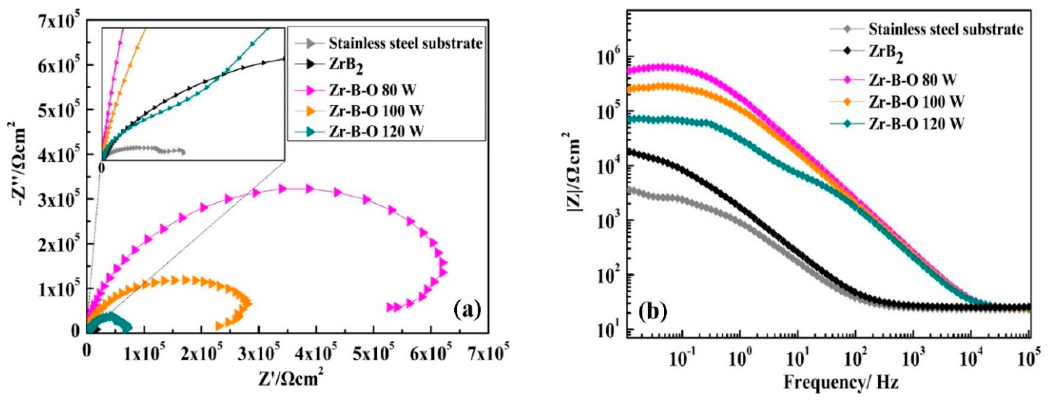
Figure 10 displays the Nyquist and Bode plots of the stainless-steel substrate, ZrB2 monolayer, and Zr-B-O nanocomposite films. The diameter of the capacitive loop of Nyquist plot and the impedance value of Bode plot are related to the corrosion resistance. The Nyquist plots in Figure 10a have similar shapes to each other. Furthermore, the capacitive loops diameter of Zr-B-O nanocomposite films is much larger than that of the stainless-steel substrate and ZrB2 monolayer. On the other hand, the impedance values of composite films increase with the reduction of sputtering power of ZrB2 target from the Bode plot in Figure 10b. This indicates that the amorphous composite films have improved the corrosion resistance of the substrate and the ZrB2 monolayer to some extent. The lower deposition power with lower bombarding energy leads to the deepening of the amorphous degree of composite films, making the composite film with 80 W sputtering power of ZrB2 have better corrosion resistance. The EIS results are consistent with polarization curves in explaining the corrosion behavior of Zr-B-O nanocomposite films.
By comparing the relationship between the above mechanical properties, oxidation resistance and corrosion resistance and combining with its structural characteristics, it is not difficult to find that such a dense amorphous structure is conducive to preventing external damage. At the low power of ZrB2, the severe amorphous structure of the thin film is conducive to improving its corrosion resistance. When the power of ZrB2 increases, the mechanical properties are promoted by increasing the relative content of ZrB2, and the oxidation resistance is enhanced by trace amounts of oxygen atoms and compact oxidation film. The amorphous structure and internal oxygen content of the films have a direct effect on these properties.
4. Conclusions
A method of mixing ZrO2 was designed to improve the oxidation and corrosion resistance of Zr-B-O nanocomposite films while maintaining the good mechanical properties of ZrB2. In the process of simultaneous deposition of ZrB2 and ZrO2 to form nanocomposite films, the crystallinity of composite films is poor due to their mutual inhibition during sputtering. The Zr-B-O nanocomposite films have high microhardness because there is still a preferred orientation of ZrB2 (001) plane in the composite films. When the power of ZrB2 target increased to 120 W, the hardness of the composite film reached up to 26.76 GPa and the corresponding elastic modulus decreased to 268.05 GPa due to the addition of ZrO2. Meanwhile, the maximum critical fracture load was up to 2.98 N. Due to the most heat absorbed by the amorphous part and lower oxygen content inside, the oxidation-mass change of the composite film with 120 W power of ZrB2 varied by only 0.1% under 1000 °C for 1 h. Conversely, the corrosion resistance of Zr-B-O nanocomposite films was negatively correlated with the sputtering power of ZrB2 target. The improved corrosion resistance was exhibited by the film with a denser amorphous structure at 80 W sputtering power of ZrB2. Thus, there is a direct correlation between mechanical properties, oxidation resistance, and corrosion resistance due to the microstructure and oxygen content of films. The power of ZrB2 will find an equilibrium value between 80 and 120 W in these properties.
Author Contributions
Conceptualization, D.L.; formal analysis, Y.X., D.M. and M.Z.; funding acquisition, D.L.; investigation, D.L.; methodology, L.D.; project administration, Y.X. and D.M.; supervision, D.L.; writing—original draft, Y.X.; writing—review and editing, L.D., J.W. and D.L.
Funding
This research was funded by the National Natural Science Foundation of China (51772209, 51901158), the Joint Funds Project of Tianjin Natural Science Foundation of China (No. 18JCQNJC72000), Tianjin Science and Technology Project (18PTZWHZ00020, 18JCQNJC73400), and Program for Innovative Research in University of Tianjin (Grant No. TD13-5077). This research was also supported by the Science & Technology Development Fund of Tianjin Education Commission for Higher Education (No. 2018KJ158).
Conflicts of Interest
The authors declare no conflict of interest.
References
- Veprek, S.; Veprek-Heijman, M.J.G. Industrial applications of superhard nanocomposite coatings. Surf. Coat. Technol. 2008, 202, 5063–5073. [Google Scholar] [CrossRef]
- Holubar, P.; Jilek, M.; Sima, M. Present and possible application of superhard nanocomposite coatings. Surf. Coat. Technol. 2000, 133, 145–151. [Google Scholar] [CrossRef]
- Sung, C.M.; Sung, M. Carbon nitride and other speculative superhard materials. Mater. Chem. Phys. 1996, 43, 1–18. [Google Scholar]
- Settineri, L.; Faga, M.G.; Gautier, G.; Perucca, M. Evaluation of wear resistance of AlSiTiN and AlSiCrN nanocomposite coatings for cutting tools. CIRP Ann. Manuf. Technol. 2008, 57, 575–578. [Google Scholar]
- Keunecke, M.; Bewilogua, K.; Wiemann, E.; Weigel, K.; Wittorf, R.; Thomsen, H. Boron containing combination tool coatings-characterization and application tests. Thin Solid Films 2006, 494, 58–62. [Google Scholar] [CrossRef]
- Li, J.; Sun, Y.; Sun, X.; Qiao, J. Mechanical and corrosion-resistance performance of electrodeposited titania-nickel nanocomposite coatings. Surf. Coat. Technol. 2005, 192, 331–335. [Google Scholar]
- Zhang, S.; Sun, D.; Fu, Y.Q.; Du, H.J. Recent advances of superhard nanocomposite coatings: A review. Surf. Coat. Technol. 2003, 167, 113–119. [Google Scholar] [CrossRef]
- Dubey, P.; Arya, V.; Srivastava, S.; Singh, D.; Chandra, R. Study on thermal stability and mechanical properties of nanocomposite Zr-W-B-N thin films. Surf. Coat. Technol. 2015, 284, 173–182. [Google Scholar]
- Kiryukhantsev-Korneev, F.V.; Sheveiko, A.N.; Komarov, V.A.; Blanter, M.S.; Skryleva, E.A.; Shirmanov, N.A.; Levashov, E.A.; Shtansky, D.V. Nanostructured Ti-Cr-B-N and Ti-Cr-Si-C-N coatings for hard-alloy cutting tools. Russ. J. Nonferrous Met. 2011, 52, 311–318. [Google Scholar]
- Yang, J.; Wang, M.X.; Kang, Y.B.; Li, D.J. Influence of bilayer periods on structural and mechanical properties of ZrC/ZrB2 superlattice coatings. Appl. Surf. Sci. 2007, 253, 5302–5305. [Google Scholar] [CrossRef]
- Yan, Y.J.; Huang, Z.R.; Dong, S.M.; Jiang, D.L. Pressureless sintering of high-density ZrB2-SiC ceramic composites. J. Am. Ceram. Soc. 2006, 89, 3589–3592. [Google Scholar] [CrossRef]
- Telle, R.; Sigl, L.S.; Takagi, K. Boride-based hard materials. In Handbook of Ceramic Hard Materials; Riedel, R., Ed.; Wiley-VCH Verlag GmbH: Weinheim, Germany, 2000; pp. 802–945. [Google Scholar]
- Monteverde, F.; Guicciardi, S.; Bellosi, A. Advances in microstructure and mechanical properties of Zirconium diboride based ceramics. Mater. Sci. Eng. A 2003, 346, 310–319. [Google Scholar] [CrossRef]
- Zou, J.; Zhang, G.J.; Kan, Y.M.; Wang, P.L. Pressureless densification of ZrB2-SiC composites with vanadium carbide. Scr. Mater. 2008, 59, 309–312. [Google Scholar] [CrossRef]
- Li, C.; Dong, L.; Wan, R.X.; Gu, H.Q.; Li, D.J. Cotrollable phase structure and mechanical properties of ZrB2-NbN nanocomposite films by magnetron co-sputtering. Mater. Express 2016, 6, 493–500. [Google Scholar] [CrossRef]
- Shi, J.Y.; Verweij, H. Preparation and characterization of nanostructured ZrO2 coatings on dense and porous substrates. Thin Solid Films 2008, 516, 3919–3923. [Google Scholar] [CrossRef]
- Zhang, K.; Liu, L.; Ren, C.; Wang, K.; Dai, G.Z.; Zheng, X.B.; He, Y.D. Preparation of Al2O3-ZrO2-Y2O3 composite coatings by a modified sol-gel technique for thermal barrier application. Oxid. Met. 2013, 80, 323–339. [Google Scholar] [CrossRef]
- Qin, W.; Nam, C.; Li, H.L.; Szpunar, J.A. Tetragonal phase stability in ZrO2 film formed on zirconium alloys and its effects on corrosion resistance. Acta Mater. 2007, 55, 1695–1701. [Google Scholar] [CrossRef]
- Li, W.J.; Zhang, X.H.; Hong, C.Q.; Han, W.B.; Han, J.C. Preparation, microstructure and mechanical properties of ZrB2-ZrO2 ceramics. J. Eur. Ceram. Soc. 2009, 29, 779–786. [Google Scholar] [CrossRef]
- Zhang, X.H.; Li, W.J.; Hong, C.Q.; Han, W.B. Microstructure and mechanical properties of ZrB2-based composites reinforced and toughened by zirconia. Int. J. Appl. Ceram. Technol. 2008, 5, 499–504. [Google Scholar] [CrossRef]
- Basu, B.; Vleugels, J.; Biest, O.V.D. Development of ZrO2-ZrB2 composites. J. Alloys Compd. 2002, 334, 200–204. [Google Scholar] [CrossRef]
- Basu, B.; Venkateswaran, T.; Kim, D.Y. Microstructure and properties of spark plasma-sintered ZrO2-ZrB2 nanoceramic composites. J. Am. Ceram. Soc. 2006, 89, 2405–2412. [Google Scholar] [CrossRef]
- Li, B.; Deng, J.X.; Wu, Z. Effect of cutting atmosphere on dry machining performance with Al2O3/ZrB2/ZrO2 ceramic tool. Int. J. Adv. Manuf. Technol. 2010, 49, 459–467. [Google Scholar] [CrossRef]
- Chen, L.; Huang, Y.H.; Wang, Y.J.; Shen, H.F.; Rao, J.C.; Zhou, Y. Effect of ZrO2 content on microstructure, mechanical properties and thermal shock resistance of (ZrB2+3Y-ZrO2)/BN composites. Mater. Sci. Eng. A 2013, 573, 106–110. [Google Scholar] [CrossRef]
- Oliver, W.C.; Pharr, G.M. An improved technique for determining hardness and elastic modulus using load and displacement sensing indentation experiments. J. Mater. Res. 1992, 7, 1564–1583. [Google Scholar] [CrossRef]
- Oliver, W.C.; Pharr, G.M. Measurement of hardness and elastic modulus by instrumented indentation: Advances in understanding and refinements to methodology. J. Mater. Res. 2004, 19, 3–20. [Google Scholar] [CrossRef]
- Mitterer, C. Borides in thin film technology. J. Solid State Chem. 1997, 133, 279–291. [Google Scholar] [CrossRef]
- Zhuang, C.Q.; Schlemper, C.; Fuchs, R.; Zhang, L.; Huang, N.; Vogel, M.; Staedler, T.; Jiang, X. Mechanical behavior related to various bonding states in amorphous Si-C-N hard films. Surf. Coat. Technol. 2014, 258, 353–358. [Google Scholar] [CrossRef]
- Zhao, B.; Li, D.M.; Zeng, F.; Pan, F. Ion beam induced formation of metastable alloy phases in Cu-Mo system during ion beam assisted deposition. Appl. Surf. Sci. 2003, 207, 334–340. [Google Scholar] [CrossRef]
- Wang, T.G.; Liu, Y.M.; Zhang, T.F.; Kim, D.; Kim, K.H. Influence of nitrogen flow ratio on the microstructure, composition, and mechanical properties of DC magnetron sputtered Zr–B–O–N films. J. Mater. Sci. Technol. 2012, 28, 981–991. [Google Scholar] [CrossRef]
- Pierson, J.F.; Billard, A.; Belmonte, T.; Michel, H.; Frantz, C. Influence of oxygen flow rate on the structural and mechanical properties of reactively magnetron sputter-deposited Zr-B-O coatings. Thin Solid Films 1999, 347, 78–84. [Google Scholar] [CrossRef]
- Zhang, G.J.; Ni, D.W.; Zou, J.; Liu, H.T.; Wu, W.W.; Liu, J.X.; Suzuki, T.S.; Sakka, Y. Inherent anisotrotropy in transition metal diborides and microstructure/property tailoring in ultra-high temperature ceramics—A review. J. Eur. Ceram. Soc. 2018, 38, 371–389. [Google Scholar] [CrossRef]
- Otani, S.; Korsukova, M.M.; Aizawa, T. High-temperature hardness of ReB2 single crystals. J. Alloys Compd. 2009, 477, L28–L29. [Google Scholar] [CrossRef]
- Feng, T.; Li, H.J.; Shi, X.H.; Yang, X.; Wang, S.L. Oxidation and ablation resistance of ZrB2-SiC-Si/B-modified SiC coating for carbon/carbon composites. Corros. Sci. 2013, 67, 292–297. [Google Scholar] [CrossRef]
- Lian, J.; Zhang, J.M.; Namavar, F.; Zhang, Y.W.; Lu, F.Y.; Haider, H.; Garvin, K.; Weber, W.J.; Ewing, R.C. Ion beam-induced amorphous-to-tetragonal phase transformation and grain growth of nanocrystalline zirconia. Nanotechnology 2009, 20, 245303. [Google Scholar] [CrossRef] [PubMed]
- Sobol, A.A.; Voronko, Y.k. Stress-induced cubic-tetragonal transformation in partially stabilized ZrO2: Raman spectroscopy study. J. Phys. Chem. Solids 2004, 65, 1103–1112. [Google Scholar] [CrossRef]
- Li, W.; Liu, P.; Chen, P.C.; Zhang, K.; Ma, F.C.; Liu, X.K.; Feng, R.; Liaw, P.K. Microstructure and a coherent-interface strengthening mechanism of NbSiN nanocomposite film. Thin Solid Films 2017, 636, 1–7. [Google Scholar] [CrossRef]
- Li, W.; Liu, P.; Zhao, S.; Zhang, K.; Ma, F.C.; Liu, X.K.; Chen, X.H.; He, D.H. Microstructural evolution, mechanical properties and strengthening mechanism of TiN/Ni nanocomposite film. J. Alloys Compd. 2017, 691, 159–164. [Google Scholar] [CrossRef]
- Lee, N.L.; Fisher, G.B.; Schulz, R. Sputter deposition of a corrosion-resistance amorphous metallic coating. J. Mater. Res. 1988, 3, 862–871. [Google Scholar] [CrossRef]
- Liu, D.G.; Tu, J.P.; Chen, R.; Gu, C.D. Microstructure, corrosion resistance and biocompatibility of titanium incorporated amorphous carbon nitride films. Surf. Coat. Technol. 2011, 206, 165–171. [Google Scholar] [CrossRef]
Figure 1.
Schematic diagram of preparation of Zr-B-O nanocomposite films by magnetron co-sputtering.
Figure 1.
Schematic diagram of preparation of Zr-B-O nanocomposite films by magnetron co-sputtering.

Figure 2.
Cross-sectional SEM image of (a) nanocomposite Zr-B-O film and top view SEM images of (b) ZrO2, (c) ZrB2, and (d) Zr-B-O films.
Figure 2.
Cross-sectional SEM image of (a) nanocomposite Zr-B-O film and top view SEM images of (b) ZrO2, (c) ZrB2, and (d) Zr-B-O films.

Figure 3.
(a) XRD patterns of ZrB2, ZrO2 monolayers and (b) Zr-B-O nanocomposite films at different sputtering power of ZrB2 target.
Figure 3.
(a) XRD patterns of ZrB2, ZrO2 monolayers and (b) Zr-B-O nanocomposite films at different sputtering power of ZrB2 target.

Figure 4.
High resolution XPS spectra of (a) Zr3d and (b) B1s of Zr-B-O nanocomposite films with 80 W sputtering power of ZrB2 target.
Figure 4.
High resolution XPS spectra of (a) Zr3d and (b) B1s of Zr-B-O nanocomposite films with 80 W sputtering power of ZrB2 target.

Figure 5.
Hardness and elastic modulus of ZrB2, ZrO2 monolayers, and Zr-B-O nanocomposite films at different sputtering powers of the ZrB2 target.
Figure 5.
Hardness and elastic modulus of ZrB2, ZrO2 monolayers, and Zr-B-O nanocomposite films at different sputtering powers of the ZrB2 target.

Figure 6.
Indentation morphology and critical fracture load of ZrB2 monolayer and Zr-B-O nanocomposite films (80 and 120 W power of ZrB2 target).
Figure 6.
Indentation morphology and critical fracture load of ZrB2 monolayer and Zr-B-O nanocomposite films (80 and 120 W power of ZrB2 target).

Figure 7.
Fitting curves of (a) oxidation-mass change and (b) XRD patterns of Zr-B-O nanocomposite films (120 W power of ZrB2 target) at different testing temperatures.
Figure 7.
Fitting curves of (a) oxidation-mass change and (b) XRD patterns of Zr-B-O nanocomposite films (120 W power of ZrB2 target) at different testing temperatures.

Figure 8.
(a) SAED patterns and (b) TEM image of Zr-B-O nanocomposite film at 120 W sputtering power of the ZrB2 target, and (c) SAED patterns and (d) elemental mapping image of Zr-B-O nanocomposite film at 120 W sputtering power of ZrB2 target after 850 °C oxidation for 1 h.
Figure 8.
(a) SAED patterns and (b) TEM image of Zr-B-O nanocomposite film at 120 W sputtering power of the ZrB2 target, and (c) SAED patterns and (d) elemental mapping image of Zr-B-O nanocomposite film at 120 W sputtering power of ZrB2 target after 850 °C oxidation for 1 h.

Figure 9.
Potentiodynamic polarization curves of the stainless-steel substrate, ZrB2 monolayer and Zr-B-O nanocomposite films in 3.5 wt.% NaCl solution.
Figure 9.
Potentiodynamic polarization curves of the stainless-steel substrate, ZrB2 monolayer and Zr-B-O nanocomposite films in 3.5 wt.% NaCl solution.

Figure 10.
Electrochemical impedance spectroscopy (EIS) plots of the stainless-steel substrate, ZrB2 monolayer and Zr-B-O nanocomposite films. (a) Nyquist plot. (b) Bode plot.
Figure 10.
Electrochemical impedance spectroscopy (EIS) plots of the stainless-steel substrate, ZrB2 monolayer and Zr-B-O nanocomposite films. (a) Nyquist plot. (b) Bode plot.


Table 1.
Fitting results of potentiodynamic polarization curves of the stainless-steel substrate, ZrB2 monolayer, and Zr-B-O nanocomposite films.
Table 1.
Fitting results of potentiodynamic polarization curves of the stainless-steel substrate, ZrB2 monolayer, and Zr-B-O nanocomposite films.
| Samples | Untreated | ZrB2 | Zr-B-O (80 W) | Zr-B-O (100 W) | Zr-B-O (120 W) |
|---|---|---|---|---|---|
| icorr (A·cm−2) | 2.9057 × 10⁻⁶ | 2.8869 × 10⁻⁶ | 4.5310 × 10⁻⁷ | 4.7362 × 10⁻⁷ | 4.9919 × 10⁻⁷ |
© 2019 by the authors. Licensee MDPI, Basel, Switzerland. This article is an open access article distributed under the terms and conditions of the Creative Commons Attribution (CC BY) license (http://creativecommons.org/licenses/by/4.0/).
Share and Cite
MDPI and ACS Style
Xu, Y.; Mao, D.; Dong, L.; Zhao, M.; Wu, J.; Li, D. Influence of Sputtering Power of ZrB2 Target on Structure and Properties of Nanocomposite Zr-B-O Films. Coatings 2019, 9, 611. https://doi.org/10.3390/coatings9100611
AMA Style
Xu Y, Mao D, Dong L, Zhao M, Wu J, Li D. Influence of Sputtering Power of ZrB2 Target on Structure and Properties of Nanocomposite Zr-B-O Films. Coatings. 2019; 9(10):611. https://doi.org/10.3390/coatings9100611
Chicago/Turabian StyleXu, Yang, Dong Mao, Lei Dong, Mengli Zhao, Jie Wu, and Dejun Li. 2019. "Influence of Sputtering Power of ZrB2 Target on Structure and Properties of Nanocomposite Zr-B-O Films" Coatings 9, no. 10: 611. https://doi.org/10.3390/coatings9100611
Note that from the first issue of 2016, this journal uses article numbers instead of page numbers. See further details here.