Article

Effect of Microstructural Modifications on the Corrosion Resistance of CoCrFeMo0.85Ni Compositionally Complex Alloy Coatings

1
TWI Ltd., Granta Park, Cambridge CB21 6AL, UK
2
Faculty of Engineering, University Politehnica Bucharest, Splaiul Independentei 313, 060042 Bucharest, Romania
*
Author to whom correspondence should be addressed.
Coatings 2019, 9(11), 695; https://doi.org/10.3390/coatings9110695
Submission received: 30 August 2019 / Revised: 22 October 2019 / Accepted: 23 October 2019 / Published: 24 October 2019
(This article belongs to the Special Issue Coatings for Harsh Environments)

Abstract

:
A compositionally complex alloy (CCA) was developed in powder form and applied as a coating onto a carbon steels substrate by using thermal spray. The purpose of this study was to investigate the effect of microstructural modification induced by using two different powder production methods, mechanical alloying and gas atomisation, onto the corrosion resistance of the coatings for a CoCrFeMo0.85Ni composition. The evolution of microstructure from powders to coatings was analysed using scanning electron microscopy coupled with energy-dispersive spectroscopy and X-ray diffraction. In order to evaluate the corrosion performance of the coatings, electrochemical corrosion tests were performed in a 3.5 wt % NaCl solution at pH = 4. The study demonstrates that the powder production method has a significant influence on the phase composition and, in turn, corrosion behaviour of the resulting coating, with the gas atomising route imparting better corrosion resistance properties. Nevertheless, the appearance of the face-centered cubic (FCC) phase characteristic of the CoCrFeMo0.85Ni alloy within the coating produced from the mechanically alloyed powder, opens the possibility for this powder manufacturing technique to effectively produce compositionally complex alloys.

1. Introduction

Compositionally complex alloys (CCAs, also referred to as high entropy alloys in literature) are multicomponent equi- or near-equiatomic alloys which form mostly solid solutions including random solid solutions and partially ordered ones. Depending on the property required, e.g. hardness, corrosion resistance, etc., a particular phase in the multiphase alloy is targeted for a specific application [1,2,3]. Successful manufacture of bulk CCAs by using traditional casting techniques can prove challenging due to large differences in both density and melting point of individual constituent elements. Therefore, solid state processing via mechanical alloying of powder and subsequent consolidation may present a more viable manufacturing route. The requirement for near-equiatomic mixtures can also lead to potentially high cost, if more exotic or costly elements are required. Deposition of CCAs as a coating onto an inexpensive substrate may provide a low-cost means of exploiting advantageous materials properties.
The corrosion resistance in NaCl solution has been studied by Qiu et al. [4], on a laser clad AlCrFeCuCo alloy. The alloy’s microstructure showed a combination of face-centered cubic (FCC) and body-centered cubic (BCC) phases and exhibited excellent corrosion resistance, which, however, was observed to vary with process deposition parameters. More recently, the microstructure and corrosion behavior of a plasma sprayed (CoCrFeNi)95Nb5 alloy was assessed by Wang et al. [5] and consisted of Laves phase within an FCC solid solution. Elemental segregation was observed, with higher melting point elements (Cu, Nb) enriching the interdendritic regions. Better corrosion performance than previously studied coatings was measured in 3.5 wt % NaCl solution, with the Cu and Nb-rich regions representing the areas of preferential corrosion. In another work by Gao et al. [6], CCA of the CoCrFeNiAl0.3 composition was produced by using radio frequency magnetron sputtering and tested in 3.5 wt % NaCl solution. The coatings consisted of a polycrystalline FCC structure with homogeneous element distribution and showed increased hardness and improved corrosion performance as compared to wrought 304 stainless steel. Some CCAs have demonstrated excellent performance in both H2SO4 and NaCl solutions. Similar to conventional alloys, it is interesting to note that Cr, Ni, Co, Ti in CCAs enhance corrosion resistance in acid solutions, Mo tends to inhibit pitting corrosion, whereas Al and Mn display a negative effect [7]. Wang et al. [8] applied thermal spray technology to fabricate coatings of the NixCo0.6Fe0.2CrySizAlTi0.2 composition. Results indicated that the hardness of the CCAs prepared by using the thermal spraying in combination with annealing at 1100 °C for 10 h was significantly increased compared to that of the cast alloy. Moreover, the alloy exhibited excellent corrosion resistance, resulting from the presence of the Cr3Si phase and several other (unidentified) phases. More recently, the effect of grain refinement and elemental partitioning onto the strength and corrosion resistance of a friction stir processed Cu-containing CCA has been evaluated by Nene et al. [9]. Their work shows that grain refinements are an important factor to enhance the strength of the alloy, while the partition of elements such as Cu within the main FCC matrix would worsen the corrosion resistance. It is clear from these studies that the corrosion behavior of CCA coatings is intrinsically linked to their microstructure, which, in turns, depends on the physical-chemical properties of the reagents (e.g., powders) used to produce the coated system.
The aim of this paper is therefore to investigate the relationship between powder and coating microstructure and its effect on the corrosion performance of the latter. As a case study, powders of the CoCrFeMo0.85Ni composition have been produced by using both solid state processing (mechanical alloying) and gas atomization and deposited by using high-velocity oxygen fuel (HVOF) spray on carbon steel substrates. The phase evolution during the various stages of CCA coating production has been evaluated by using scanning electron microscopy (SEM), energy-dispersive X-ray spectroscopy (EDX) and X-ray diffraction (XRD), while the corrosion performance was evaluated in 3.5 wt % NaCl solution through the linear polarization resistance technique.

2. Materials and Methods

2.1. Materials and Processing

Mechanically alloyed powders were produced from powders of pure elements Co, Cr, Fe, Ni and Mo (Laboratorium®, Bucharest, Romania), processed with a planetary ball mill (Fritsch–Pulverisette 6®, Idar-Oberstein, Germany) for an effective time of 210 min. Elemental powders were placed in stainless steel vial with stainless steel balls in a 10:1 ball to powder weight ratio for this particular composition. The wet milling process was selected, in 2% n-heptane, in order to increase the alloying ratio and decrease the tendency of the powders to adhere onto the balls or vials. From the overall batch of powder produced, a −56 + 20 μm size distribution was extracted by using mechanical sieving. Gas atomized powders were produced under argon atmosphere (HERMIGA 75/5 VI EAC, Phoenix Scientific Industries Ltd., Brighton, UK), with an estimated cooling rate of 105–106 °C/s. A powder of final size distribution −48 + 15 μm was finally obtained by means of mechanical sieving. The composition of the materials employed in the work is reported in Table 1 for both powders (reported as nominal weight of elements used for mechanical alloying and gas atomisation) and substrate (as provided by the manufacturer).
The depositions were performed by using a Praxair Surface Technologies (Indianapolis, USA) Tafa Model 5220 HP/HVOF® gun by using kerosene as fuel gas and nitrogen as powder carrier. The set of deposition process parameters, employed for both mechanically alloyed (MA) and gas atomised (GA) powders, is reported in Table 2.
Substrates measuring 25 mm × 25 mm × 6 mm were grit blasted with 60 mesh brown alumina and degreased with acetone prior to deposition.

2.2. Microstructural Analyses

A Zeiss® Supra 25, equipped with an Energy Dispersive X-Ray Spectroscopy detector (EDX, Oxford Instruments®, Oxford, UK) was employed as field emission scanning electron microscope (FE-SEM) for microstructural and chemical analysis. Coating surfaces and cross-sections were analysed before and after corrosion testing. Cross-sections were prepared by mounting specimens in thermosetting phenol formaldehyde resin (Bakelite) and polishing with both SiC abrasive paper and diamond paste to a final roughness of approximately 0.025 μm Ra. The phase composition of both powders and coatings was studied by using X-ray diffraction (XRD) and a Bruker® D8 Advance diffractometer 40 kV, 30 mA, Cu-Kα radiation with λ = 1.5406 Å.

2.3. Electrochemical Corrosion Testing

Coating degradation was assessed by means of linear polarisation resistance test, by using an ACM Instruments® Gill 16 electrochemical system. (Lancaster, UK) In the electrochemical test cell, a saturated calomel electrode (SCE) and platinated titanium electrode were used as reference and auxiliary (counter) electrode respectively. Results were analysed using the ACM® Core Running software (v5.0) A 3.5 wt % NaCl aqueous solution at room temperature (25 °C) and constant pH = 4 was employed. The pH was controlled by adding HCl 7.5 M solution during the experiments. Measurements were taken at −/+ 10 mV ΔE versus the corrosion potential, at a 10 mV/min scanning rate for 168 h with measurement taken every 15 min. This time was selected as blistering was observed to occur within the coating from mechanically alloyed powder, for which it has been decided to end both tests at 168 h (i.e., 7 days).

3. Results

3.1. CCA Composition Design

The composition of the CCA alloy employed in this work was designed according to theoretical calculations of solid solution formation parameter (Ω), entropy of mixing (ΔSmix), enthalpy of mixing (ΔHmix), atomic size difference (δ) and valence electron concentration (VEC) [10]:
Ω = T m Δ S mix Δ H mix
Δ S mix = R i = 1 n c i l n c i
Δ H mix = i = 1 ,   i j n 4 Δ H i j mix c i c j
δ = i = 1 n c i ( 1 r i r ¯ )
V E C = i = 1 n c i V E C i
where n is the number of components, i and j refer to a specific component, c is the atomic fraction, Tm is the melting point of the alloy (defined by the mixing rule), R is the ideal gas constant, Δ H i j m i x is the enthalpy of mixing of elements i and j, r is atomic radius and r ¯ = Σ c i r i is the average radius of the alloy.
These thermodynamic parameters can be used in an attempt to predict the phases and crystal structure of a CCA. According to the criteria of phase stability formation calculated by Zhang et al. [11], if Ω ≥ 1.1 and δ ≤ 6.6 then the solid solution forms. Takeuchi et al. [12] studied the effects of changes in the mixing entropy, ΔSmix, on the crystal structure formation. Their findings suggest that the high mixing entropy provided by CCAs could overcome the enthalpy of formation of strong intermetallic compounds, thereby suppressing their generation in favor of a random solid solution. Additionally, the VEC seems to play a decisive role in determining whether FCC or BCC crystal structure solid solution forms in CCAs. Specifically, a high VEC (≥8) favors the formation of FCC-type solid solutions, while a lower VEC (<6.87) favors the formation of BCC-type solid solutions, according to Guo et al. [13].
In this work, the CCA composition was selected based on its likelihood to provide significant performance in terms of both tribological and corrosion resistance. For tribological performance (e.g., resistance to erosion), a mixture of FCC and BCC structures would be expected to provide adequate performance as the FCC phase is expected to present a ductile nature while the opposite holds for a BCC crystal structure [14]. Resistance to corrosion is instead expected to be enhanced by elements such as Ni, Mo, and Cr, due to the formation of passive films on the alloys surface [15]. Therefore, based on the above guidelines and following previous promising work on the CCA of the CoCrFeMoxNi class as material for corrosion protection in corrosive geothermal steam [16], this alloy class was selected for further analysis. After an iterative design study on several possible Mox concentrations, the CoCrFeMo0.85Ni composition was identified as CCA for this study. The thermodynamic parameters in Equations (1) to (5) above, calculated for the CoCrFeMo0.85Ni alloy, are reported in Table 3. Calculations take into account only the component type and not the fabrication method, so the values are identical for both GA and MA powder.

3.2. Microstructure of Powders and Coatings

SEM micrographs of the MA and GA powders are reported in Figure 1. As expected, two completely different morphologies are revealed in the two powders: an irregular shape, with particles of angular and blocky geometry (MA) and homogeneous spherical particles (GA).
This morphological variation can be attributed to the differences in the mechanical and thermodynamic processes involved in the two manufacturing methods. Mechanical alloying (MA) uses mechanical impact which generates high localized pressure, to break and bond together particles of the elements to be alloyed. The gas atomisation method (GA) instead, relies on the in-flight solidification of particles directly atmoised from a melt of the alloy composition. The spherical geometry then naturally arises due to its lower Gibbs free energy over that of other possible geometries. Localised EDX analysis on the mechanically alloyed powder demonstrates that the bright regions (marked as A in Figure 1a) are composed of Mo with only traces of the other CCA elements, Co, Cr, Fe and Ni. A variable composition is instead probed in other grey regions in the powder, such as region B, where no clear compositional pattern could be found. This compositional variation, which would suggest incomplete alloying, was somewhat expected at the short total alloying time employed in this study, 210 min, selected in an attempt to provide a final powder size distribution processable by means of HVOF. It is therefore likely that a composition close to the CCA could be achieved at further mechanical alloying processing time, however with a corresponding reduction in particles’ nominal size distribution. Bulk EDX patterns for both powders show similar elemental distribution, although a reduced concentration of Mo is measured in the gas atomised powder, likely due to the differences in vapour pressure between the elements during the melting and solidification of this latter process. EDX analysis performed on the GA powder did not reveal any localised area of a composition different from the theoretical CCA. XRD spectra for the two powders are presented in Figure 2.
The scans revealed a clear distinction between the phases identified in the two powders. The MA powder showed peaks characteristic of the single elements composing the CCA (i.e., Ni, Cr, Fe FCC and Mo BCC), thus suggesting incomplete alloying as previously suggested by EDX analysis. The elemental peaks did not appear to be present in the GA powder, where instead new peaks corresponding to the FCC and BCC phases of the CoCrFeMo0.85Ni composition appeared, thus suggesting the attainment of solid solution. The fact that the measured 2θ location for these peaks corresponds to the same angles was also identified by Shun et al. [17] on the same alloy composition. Moreover, as in [17], peaks corresponding to the intermetallic σ and π phases were also measured. It is likely that the FCC phase was stabilized and rich in elements showing a stable FCC structure (Co, Fe and Ni), while the BCC and the small amount of σ phase could be stabilized by Mo.
The microstructure of the resulting MA and GA coatings, obtained from HVOF deposition of the powders in Figure 1, is reported in Figure 3. Average thicknesses for the two coatings have been measured as ~130 and ~250 μm for MA and GA respectively.
The cross-sections show some interesting features. There seems to be a clear difference in terms of phase distribution in the two coatings. While the GA system showed a homogeneous distribution of what appeared to be a single phase, splats of different composition were observed in the MA system. An EDX analysis of the regions of differing contrast within the MA coating (Figure 3b) showed that the light grey matrix (labelled as A in Figure 3b) exhibited peaks for all of the CCA components and is thus likely to represent the FCC (or BCC) structure characteristic of the CoCrFeMo0.85Ni composition. The darker grey area (labelled as B in Figure 3b), exhibited similar peaks, but indicated a lower concentration of the element Mo compared with region A. Mo was also the main element composing the lightest region (labelled C in Figure 3b), which would suggest the presence of powder particles of elemental Mo within the initial powder. Due to the extremely high solidification rates experienced during HVOF deposition, it is unlikely that these Mo-rich regions could be formed by elemental segregation during solidification.
In order to further investigate the nature of the phases observed, XRD analysis was performed on the two coatings, as reported in Figure 4.
The phases present in the MA coating are a mixture of FCC and BCC phases characteristic of the CCA composition, together with some residual BCC linked to the Mo component and newly developed σ/μ phases. This suggests that alloying occurred in-flight during the thermal spray operation. The coating procedure, with exposure of the powder at very high temperature followed by rapid cooling, promoted the appearance of a small amount of BCC phase stabilized by the FeCr pair. The same phenomenon was observed in the CoCrFeMoNi high entropy alloy processed by using vacuum arc remelting and the BCC phase was present in the structure due to the rapid cooling process [18]. The coating also shows the appearance of oxide phases, naturally generated within the oxidising atmosphere of the thermal spray process. Conversely, similar phases were observed in both GA coating and powder, suggesting that limited modifications occurred in-flight, during the thermal spray operation. The only difference between the GA coating and powder was the appearance of oxide peaks, as expected from the thermal spray operation.

3.3. Electrochemical Corrosion Testing

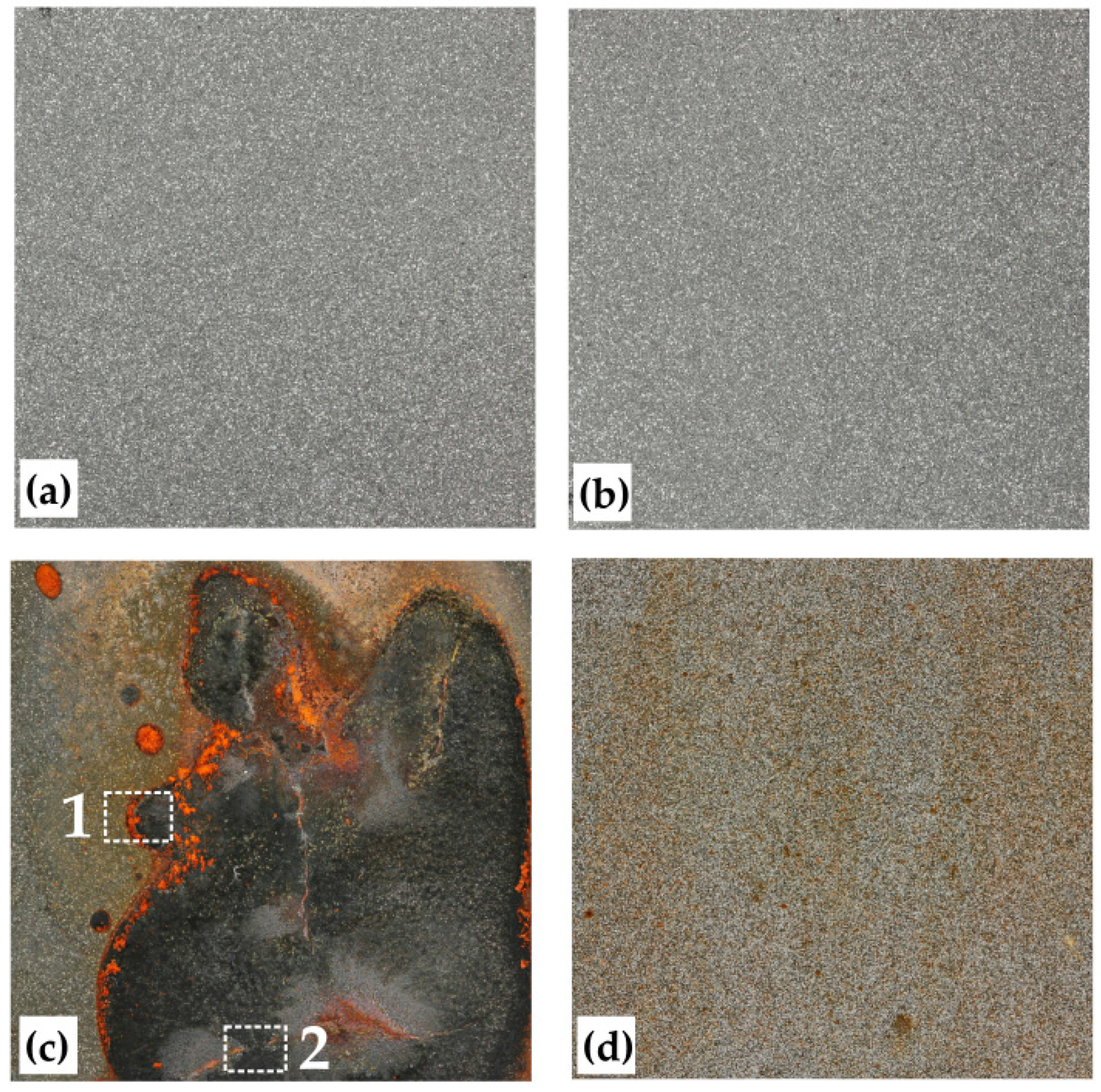
Photographs of the surfaces of the coated specimens are presented in Figure 5 for both MA and GA before and after exposure to the corrosion environment.
While the appearance of the as-deposited coatings was comparable between the two coatings (Figure 5a,b), the condition post exposure showed significant differences. In the MA coating, corrosion products and cracks were observed, while no cracking was visible in the GA system. However, the presence of localised discoloured spots was visible in the GA system. In the case of MA system, it is proposed that permeation of the corrosive solution through the coating has occurred. The permeation of the solution would have led to corrosion of the underlying carbon steel substrate, thereby generating corrosion products. The likely corrosion products for carbon steel would be mixtures of compounds of the steel constituents, which have a Pilling–Bedworth (P–B) ratio >1.5. Pilling–Bedworth ratio is the ratio of the volume of the metal oxide formed from a volume of the corresponding metal (from which the oxide is created). The high P–B ratio indicates that the growth of the corrosion product under the coating would lead to tensile stresses on the top surface of the coating which might crack once the stresses reach a critical level. A more in-depth analysis (SEM-EDX) of regions 1 and 2 in Figure 5c is presented in Figure 6a,b respectively.
Figure 6a shows regions of different appearance, corresponding to various corrosion products. An EDX analysis of the three highlighted regions shows the lighter region on the left-hand side of the figure (region 1) containing primarily the constituents of the CCA (i.e., Co, Cr, Fe, Ni and Mo), with Fe having the highest concentration, together with elements O, Cl and Na. The presence of Cl and Na were likely due to the adhering salt solution on the rough coating surface. The darker region 2 is largely dominated by the element Fe, with the additional presence of Cl and O and some traces of the elements of the CCA. Finally, region 3 exhibited peaks comparable to region 2, but with a higher concentration in CCA elements, likely due to a reduced thickness of the oxide layer in the former region.
Two types of cracks can be identified in the corroded MA specimen, as is clear from the cross-section micrographs in Figure 7. Figure 7a shows a vertical crack within the coating at a location of coating detachment. This type of crack is likely generated by mechanical stresses created by the growth of corrosion product at the substrate/coating interface. The substrate/coating delamination is linked to the low toughness of the corrosion product generated at the substrate/coating interface, as depicted by the SEM micrograph in Figure 7b, which shows the location of crack initiation. The effect of stress-induced coating cracking from growth of corrosion products has already been observed [19].
In the case of the GA coating (Figure 5d), although localised darker areas were observed, the discolored appearance suggests that corrosion products have started to form, even if not covering the entire surface. An in-depth SEM-EDX analysis of the coating surface is presented in Figure 8.
The low-magnification micrograph, Figure 8a, shows the presence of darker areas on the coating surface (highlighted by red arrow in the figure), representing a combination of initial surface porosity and localised areas of corrosion (as also seen in Figure 5d). EDX analysis performed at high-magnification (Figure 8b), showed that the lighter particles (region 1), of flat splat-like morphology, contain the CCA elements in the theoretical stoichiometry, while Fe has the highest concentration amongst the other CCA elements in the dark areas (region 2). This would suggest that corrosion was occurring preferentially in those regions. An in-depth analysis of this effect is provided by an SEM-EDX analysis of the specimen cross-section (
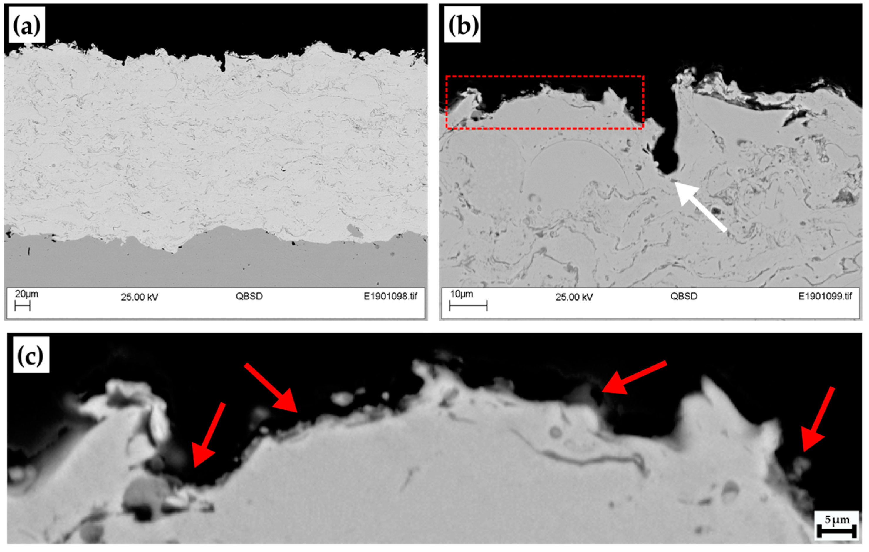
Figure 9).
The low-magnification micrograph (Figure 9a) showed no evidence of through-coating permeation, while higher magnification micrographs (Figure 9b,c) showed evidence of corrosion products. These corrosion products could not be uniquely identified by using XRD or EDX analysis due to their small dimensions. It is worth noting the feature identified by a white arrow in Figure 9b, where the shape observed is unlikely to be representative of an as-deposited coating, due to the tall vertical wall observed at the right side. This, together with analysis of current density data showing several peaks, suggests that pitting occurred in the specimen at such locations. Areas on the bottom of features in rough specimens generate localized areas of higher Cl concentration, therefore locally increasing the dissolution kinetics of the metal. It is suggested that in this sample, the passive film naturally generated on the surface breaks down at localized areas of higher roughness. If the local breakdown region is then re-passivated, and if the solution is agitated so as to take away loosely bound corrosion products from the surface, it is possible that a continuous depassivation/re-passivation cycle is repeated. This may explain the absence of corrosion product on the bottom of the identified feature.
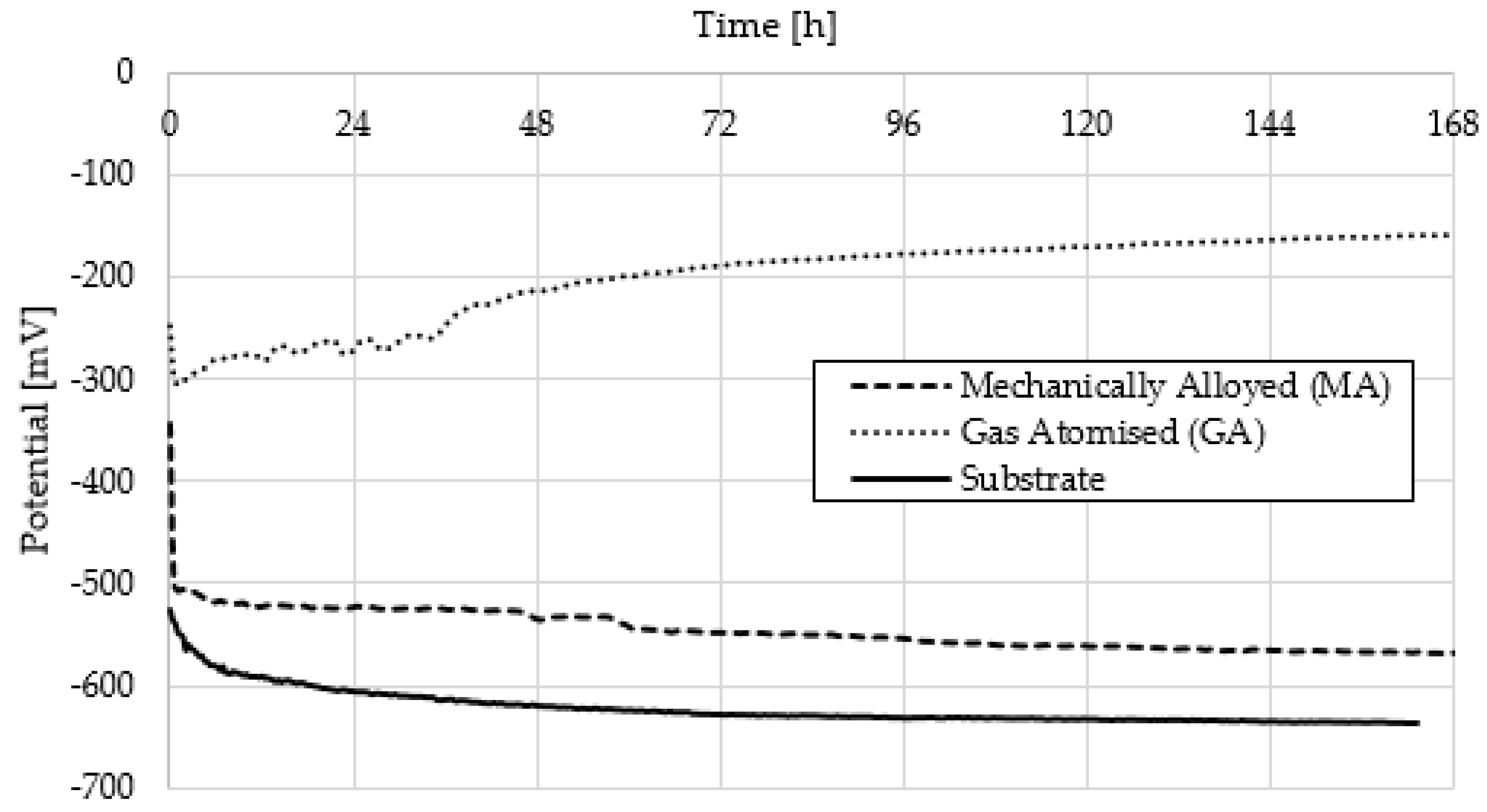
Finally, an understanding of the corrosion mechanism can be appreciated also by analysing the corrosion potential over time for the two specimens as well as the substrate alone (Figure 10). The two coatings show different behaviours. The corrosion potential of the MA coating showed a decreasing trend throughout the test, which approached asymptotically the corrosion potential of the substrate. This would confirm that the corrosive solution had reached the interface between coating and substrate, causing the latter to preferentially corrode. The potential gap between MA coating and substrate is given by the fact that it is likely that not only is the substrate corroding but a mixture between coating and substrate. The gas atomized coating (GA), conversely, showed a corrosion potential of increasing trend and of much higher magnitude compared with the GA coating and substrate. This increasing trend could be justified either by the formation and growth of a passive film on the coating surface or closing of open porosity (naturally present within the as-deposited coating) or a combination of the two. This possible phenomenon needs to be further verified by further testing.
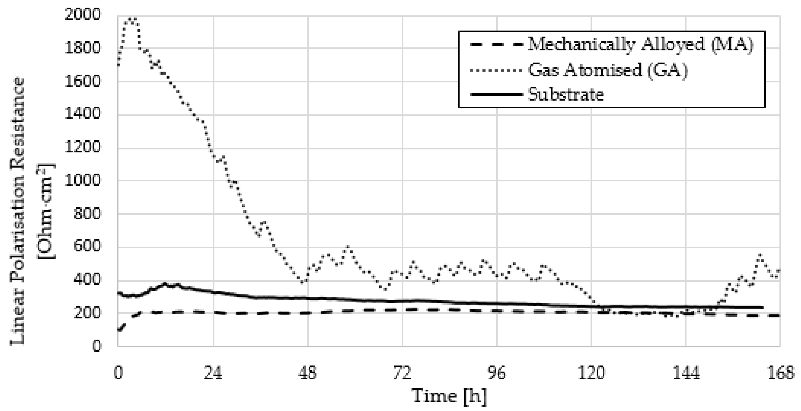
Further insights can be provided by analyzing the linear polarization resistance (LPR) curves of the systems tested (Figure 11).
The values measured for the MA and substrate systems exhibit a rather constant behavior throughout the exposure, suggesting that uniform corrosion is occurring. The low absolute LPR values measured for these two systems show that little resistance to the corrosive environment at the conditions employed. A different behavior is observed in the GA system, with an initially higher LPR followed by a decreasing trend with exposure time. This trend suggests the initial generation of a passive film onto the coating surface, followed by breakdown as exposure progresses. The local spikes observed in the curve of the GA system suggests local passive film formation/breakdown, which could be corresponding to the events observed at the areas of higher localised roughness (see Figure 9). The nature and formation mechanism of passive film onto Cr and Mo-containing alloys has received considerable interest during the years. For instance, Duarte et al. [15] have evaluated the passivation scheme for amorphous and nanocrystalline Fe50Cr15Mo14C15B6 stainless-type glass-forming alloy. According to the study, although the crystallinity and nature of the corrosive environment have a great effect on the nature of the passive film, in general the Fe element is observed to corrode first, followed by a surface enrichment in Cr due to the passive film generation. The growth and/or breakdown of the passive film is then a complex phenomenon, driven by the specific alloy composition due to the formation of Cr-depleted and Mo-rich regions within the material. Although this cannot be conclusively proven by this work, it is likely that the more homogeneous nature of the phases present within the GA-type coating could lead to the consistent formation of a Cr-rich passive layer on the exposed splats’ surface, with local breakdowns only linked to the rough nature of the surface, generating localized areas of high ions concentration. Conversely, it is likely that the inhomogeneous nature of the MA coating, with splats of single elements composition, leads to the quick preferential corrosion of Fe-rich regions already within the initial stages of exposure, thus irreversibly damaging the coating structure and generating preferential paths for corrosive medium permeation. In this case, the rapid corrosion kinetics of the Fe-rich phases highly overcomes the possible formation of passive films on other areas of the coating. It is worth noting that open porosity was present in both as-deposited MA and GA coating systems at comparable levels (see Figure 3). The fact that permeation was observed only within specimen MA, and the fact that multiple phases (as opposed to the solid solution of specimen GA) are present within this coating, would suggest that galvanic effects between phases have a major effect in generating preferential corrosion paths.
Finally, it is worth noting that the LPR approach employed for corrosion evaluation, only acts as a preliminary approach to corrosion evaluation. Additional electrochemical tests are currently being undertaken on freestanding coatings to understand the fundamental passivation/depassivation mechanisms which determine the corrosion behaviour of the studied systems.

4. Discussion

The mutual solubility between solvent and solute components in a binary alloy system could be judged by using Hume-Rothery rules, namely, crystal structure, atomic size difference, valence and electronegativity. In fact, all these factors also influence the interaction between different elements and make the enthalpy of mixing either negative (attractive interaction leading to ordering and the formation of intermetallic compounds), positive (repulsive interaction leading to clustering and segregation) or near zero (leading to the formation of disordered solid solutions). The competition between enthalpy of mixing and entropy of mixing further affects the solubility between two components. When solubility is limited, terminal solid solutions (rich in one specific component) can be obtained. When a solid solution forms at all compositions, the system is called isomorphous. However, continuous solid solutions in binary alloy system are not common because the conditions for their formation are very strict to fulfill [20].
In compositionally complex alloys, the high entropy developed enhances the mixing of elements and therefore could stabilize the solid solution formation over intermetallic compounds. Conversely, when a large positive mixing enthalpy occurs only between some specific elements of the alloy, strong elemental segregation might occur [21]. The phases expected from CALPHAD® calculations on the CoCrFeMo0.85Ni alloy at room temperature are an FCC phase and σ, or σ + μ phases [17,22] The formation of σ phase is an indication that different types of solid solutions in CCAs could form depending on the interaction and atomic size difference between elements and not just the configurational entropy alone. The σ phase is in fact a topologically close-packed phase in which components with larger atomic size occupy one specific set of lattice sites while smaller atoms occupy another set so as to get a higher amount of bonding to lower their overall free energy, although their interactions (or enthalpy of mixing) between components are small [18] Within the CCA of composition CoCrFeMoxNi, both σ and μ phases have been proven to be (Mo,Cr)-rich phases, with the μ phase likely generated from σ due to high stresses generated during solidification [17]. The presence of these hard intermetallic phases has been proven to strengthen the overall alloy with ductile FCC CoCrFeNi matrix [22]. If it could be demonstrated that this strengthening effect holds true, and if the corrosion resistance of the same alloy is proven satisfactory, the CCA studied in this project can be effectively employed as an erosion-corrosion barrier for geothermal applications [18].
An in-depth analysis of XRD data (Figure 4) showed that both coatings produced in this work, MA and GA, present a mixture of FCC and BCC phases, together with a reduced presence of a combination of σ and μ. The presence of the BCC phase is important for applications involving tribological resistance as this phase could provide improved mechanical properties, such as higher yield strength, than that of FCC CCAs. The presence of the BCC phase in the CoCrFeMo0.85Ni alloy was not observed by Shun et al. on alloys produced by using arc melting. Strictly speaking, CALPHAD calculations performed by Liu at al. [22] on the same alloy class show that only FCC, σ and μ phases are the predicted stable phases at room temperature for the specific composition under analysis and a BCC stability region appears only for mole fractions of Mo higher than ~0.4 and high temperatures (>1500 °C). The appearance of BCC phase, at room temperature, in the coatings produced by using thermal spray in this work would thus suggest that a metastable BCC phase is generated at high temperature in Mo-rich regions (created by local-solute segregation during solidification) and then retained after the material has solidified, due to the extremely high solidification rate characteristic of the thermal spray technique [23]. For the MA coating, a small peak corresponding to the BCC phase of the CCA alloy appears overlapped with a shoulder containing contributions from the BCC CCA phase and σ/μ phases (Figure 4). Note that the peaks of this overlapped region do not coincide with the location of the FCC (Ni, Fe and Cr) peak, originally present in the MA powder. Moreover, it is interesting to note that some of the BCC phase characteristic of the Mo-rich compounds, originally present in the MA powder, is also retained in the coating system, suggesting that not all of the Mo particles present in the powder have alloyed during the process.
However, perhaps the most interesting feature observed in the MA coating system, compared with its parent powder, is the appearance of the FCC peak characteristic of the CCA composition. The presence of this peak suggests that, although alloying was not observed in the original powder, this has been developed during the spray operation. This is a surprising finding as one would expect, from an observation of the SEM micrograph in Figure 1a that the loosely bounded powder flakes would detach from each other in-flight. The presence of the FCC phase in the coating instead suggests that a degree of bonding has been attained by the flakes in the MA powder, with the consequence that component mixing can occur in-flight (Figure 12).
A more simplistic situation is provided by the GA system, where the same phases were observed both in the powder and coating. The gas atomization process was sufficient to generate alloying for the composition under analysis. The presence of the metastable BCC phase within the GA powder would suggest the influence of solidification kinetics in the process, due to the extremely high solidification rates attained during gas atomization. It should be mentioned that phase type prediction has been here performed in a qualitative manner from constituent-elements features and/or unlike-atomic pairs features, thus in accordance with the Hume-Rothery rules. These rules, while being comprehensive, do not allow for an accurate prediction because CCAs involve multi-elements and many unlike atomic pairs. The thermodynamic parameters calculated for the CCA composition of this work (see Table 3), are at the border between an alloy with pure FCC and a combination of FCC + BCC phases and therefore a limited quantity of BCC phase was expected. As observed from the results of this work, the phases present in the final alloy material did not always match what predicted, even by using thermodynamic calculations performed by powerful instruments such as CALPHAD and considerations on the kinetics of phases’ formation must also be accounted for. Nevertheless, the appearance of the CCA solid solution FCC and BCC phases in the coating produced from mechanically alloyed powder is very promising as it opens the possibility to manufacture coatings of any specific CCA composition by means of mechanical alloying, as opposed to more traditional and complex technologies, such as gas atomization. However, the poor corrosion results obtained by the mechanically alloyed coating, compared with the gas atomized one, also suggest that more work is required in order to optimize the coating microstructure and attain a more homogeneous phase distribution within the final system.

5. Conclusions

The powder-to-coating phase evolution and its influence on the corrosion properties of a compositionally complex alloy (CCA) of the composition CoCrFeMo0.85Ni has been assessed by means of scanning electron microscopy-electron dispersive X-ray spectroscopy (SEM-EDX), X-ray diffraction (XRD) and linear polarisation resistance (LPR). Mechanical alloying (MA) and gas atomisation (GA) have been employed as powder production techniques and coatings were deposited, at the same deposition conditions for the two powders, by means of high-velocity oxygen fuel spray (HVOF).
The research has highlighted the following main findings:
  • For the same CCA composition, the powder manufacturing process has a significant influence on the microstructure of the final coating, even when manufactured using the same deposition conditions. While a homogeneous phase distribution was observed in the coating produced from GA powder, splats of different composition were observed in the coating produced via the MA route.
  • The corrosion performance of the two coatings depended significantly on the coating microstructure. Despite similar levels of porosity, less corrosion resistance was observed in the MA coating compared with the GA coating. This was attributed to galvanic effects provided by the non-homogeneous phase distribution within the MA coating. Therefore, further optimisation of the mechanical alloying powder production parameters is suggested in order to improve the corrosion resistance properties of CCAs manufactured by this route.
  • Both MA and GA coatings are characterised by FCC, BCC and a combination of σ + μ phases characteristic of the CCA composition. However, the coating generated from the MA powder also shows the presence of original BCC phase characteristic of Mo-rich compounds. The presence of CCA-characteristic phases within the MA coating was surprising as these phases were not detected within the original powder. This opens the possibility to employ the mechanical alloying route of powder production for the manufacture of CCA coatings as opposed to more costly techniques such as gas-atomisation.

Author Contributions

Data curation, I.C.; Investigation, F.F. and L.E.G.; Supervision, S.P.; Writing—original draft, F.F.; Writing—review & editing, I.C. and H.B.

Funding

This work is part of the H2020 EU project Geo-Coat: “Development of novel and cost-effective corrosion resistant coatings for high temperature geothermal applications” funded by the H2020 EU project no. 764086.

Acknowledgments

The authors would also like to acknowledge the resources and collaborative efforts provided by the consortium of the Geo-Coat project.

Conflicts of Interest

The authors declare no conflict of interest.

References

  1. Zhang, Y.; Zuo, T.T.; Tang, Z.; Gao, M.C.; Dahmen, K.A.; Liaw, P.K.; Lu, Z.P. Microstructure and properties of high entropy alloys. Prog. Mater. Sci. 2014, 61, 1–93. [Google Scholar] [CrossRef]
  2. Koundinya, N.T.B.N.; Babu, C.S.; Sivaprasad, K.; Susila, P.; Babu, N.; Baburao, J. Phase evolution and thermal analysis of nanocrystalline AlCrCuFeNiZn high entropy alloy produced by mechanical alloying. J. Mater. Eng. Perform. 2013, 2, 3077–3084. [Google Scholar] [CrossRef]
  3. Tsai, K.Y.; Tsai, M.H.; Yeh, J.W. Sluggish diffusion in Co–Cr–Fe–Mn–Ni high-entropy alloys. Acta Mater. 2013, 61, 4887–4897. [Google Scholar] [CrossRef]
  4. Qiu, X.W.; Zhang, Y.P.; He, L.; Liu, C. Microstructure and corrosion resistance of AlCrFeCuCo high entropy alloy. J. Alloy. Compd. 2013, 549, 195–199. [Google Scholar] [CrossRef]
  5. Wang, W.; Qi, W.; Xie, L.; Yang, X.; Jiantao, L.; Zhang, Y. Microstructure and Corrosion behavior of (CoCrFeNi)95Nb5 high-entropy alloy coating fabricated by plasma spraying. Materials 2019, 12, 694. [Google Scholar] [CrossRef]
  6. Gao, L.; Liao, W.; Zhang, H.; Surjadi, J.U.; Sun, D.; Lu, Y. Microstructure, mechanical and corrosion behaviors of CoCrFeNiAl0.3 high entropy alloy (HEA) films. Coatings 2017, 7, 156. [Google Scholar] [CrossRef]
  7. Chen, Y.Y.; Duval, T.; Hung, U.D.; Yeh, J.W.; Shih, H.C. Microstructure and electrochemical properties of high entropy alloys-a comparison with type-304 stainless steel. Corros. Sci. 2005, 47, 2257–2279. [Google Scholar] [CrossRef]
  8. Wang, L.M.; Chen, C.C.; Yeh, J.W.; Ke, S.T. The microstructure and strengthening mechanism of thermal spray coating NixCo0.6Fe0.2CrySizAlTi0.2 high entropy alloys. Mater. Chem. Phys. 2011, 126, 880–885. [Google Scholar] [CrossRef]
  9. Nene, S.; Frank, M.; Liu, K.; Sinha, S.; Mishra, R.; McWilliams, B.; Cho, K. Corrosion-resistant high entropy alloy with high strength and ductility. Scr. Mater. 2019, 166, 168–172. [Google Scholar] [CrossRef]
  10. Ye, Y.; Wang, Q.; Lu, J.; Liu, C.; Yang, Y. High-entropy alloy: Challenges and prospects. Mater. Today 2016, 19, 349–358. [Google Scholar] [CrossRef]
  11. Zhang, Y.; Zhou, Y.J.; Lin, J.P.; Chen, G.L.; Liaw, P.K. Solid-Solution phase formation rules for multi-component alloys. Adv. Eng. Mater. 2008, 10, 534–538. [Google Scholar] [CrossRef]
  12. Takeuchi, A.; Inoue, A. Classification of bulk metallic glasses by atomic size difference, heat of mixing and period of constituent elements and its application to characterization of the main alloying element. Mater. Trans. JIM 2005, 46, 2817–2829. [Google Scholar] [CrossRef]
  13. Guo, S.; Ng, C.; Lu, J.; Liu, C.T. Effect of valence electron concentration on stability of fcc or bcc phase in high entropy alloys. J. Appl. Phys. 2011, 109, 1–6. [Google Scholar] [CrossRef]
  14. Tang, Z.; Zhang, S.; Cai, R.; Zhou, Q.; Wang, H. Designing High Entropy Alloys with dual fcc and bcc solid-solution phases: Structures and mechanical properties. Metall. Mater. Trans. A 2019, 50, 1888–1901. [Google Scholar] [CrossRef]
  15. Duarte, M.; Klemm, J.; Klemm, S.; Mayrhofer, K.; Stratmann, M.; Borodin, S.; Romero, A.; Madinehei, M.; Crespo, D.; Serrano, J.; et al. Elemental-Resolved Corrosion Analysis of Stainless-Type Glass-Forming Steels. Science 2013, 341, 372–376. [Google Scholar] [CrossRef]
  16. Csaki, I.; Karlsdottir, S.N.; Stefanoiu, R.; Geambazu, L.E. Corrosion Behaviour in Geothermal Steam of CoCrFeNiMo High Entropy Alloy; NACE: Phoenix, AZ, USA, 2018. [Google Scholar]
  17. Shun, T.T.; Chang, L.Y.; Shiu, M.H. Microstructure and mechanical properties of multiprincipal component CoCrFeNiMox alloys. Mater. Charact. 2012, 70, 63–67. [Google Scholar] [CrossRef]
  18. Karlsdottir, S.N.; Geambazu, L.E.; Csaki, I.; Thorhallsson, A.I.; Stefanoiu, R.; Magnus, F.; Cotrut, C. Phase evolution and microstructure analysis of CoCrFeNiMo high-entropy alloy for electro-spark-deposited coatings for geothermal environment. Coatings 2019, 9, 406. [Google Scholar] [CrossRef]
  19. Wang, Y.; Huang, Z.; Yan, Q.; Liu, C.; Liu, P.; Zhang, Y.; Guo, C.; Jiang, G.; Shen, D. Corrosion behaviors and effects of corrosion products of plasma electrolytic oxidation coated AZ31 magnesium alloy under the salt spray corrosion test. Appl. Surf. Sci. 2016, 378, 435–442. [Google Scholar] [CrossRef]
  20. Murty, B.S.; Yeh, J.W.; Rangathan, S. High Entropy Alloys; Butterworth-Heinemann Elsevier: Oxford, UK, 2012; p. 14. [Google Scholar]
  21. Liu, W.H.; Wu, Y.; He, J.Y.; Nieh, T.G.; Lu, Z.P. Grain growth and the Hall-Petch relationship in a high-entropy FeCrNiCoMn alloy. Scr. Mater. 2013, 68, 526–529. [Google Scholar] [CrossRef]
  22. Liu, W.; Lu, Z.; He, J.; Luan, J.; Wang, Z.; Liu, B.; Liu, Y.; Chen, M.; Liu, C. Ductile CoCrFeNiMox high entropy alloys strengthened by hard intermetallic phases. Acta Mater. 2016, 116, 332–342. [Google Scholar] [CrossRef]
  23. Fanicchia, F.; Maeder, X.; Ast, J.; Taylor, A.; Guo, Y.; Polyakov, M.; Michler, J.; Axinte, D. Residual stress and adhesion of thermal spray coatings: Microscopic view by solidification and crystallisation analysis in the epitaxial CoNiCrAlY single splat. Mater. Des. 2018, 153, 36–46. [Google Scholar] [CrossRef]
Figure 1. SEM micrograph of (a) mechanically alloyed (MA) powder and (b) gas atomized (GA) powder. The presence of particles of different composition is clearly visible in the MA powder.
Coatings 09 00695 g001
Figure 2. XRD scans for the mechanically alloyed (MA, top) and gas atomised (GA, bottom) powders. The MA powders show peaks related to the single elements of the CCA, while new face-centered cubic (FCC) and body-centered cubic (BCC) peaks are observed in the GA powder, suggesting that alloying has occurred.
Coatings 09 00695 g002
Figure 3. SEM micrographs of coatings cross-section for (a,b) MA and (c,d) GA coatings. For the MA powder, the inhomogeneity of the initial powder was also observed in the resulting coating, while a more uniform phase distribution was observed for the GA system.
Coatings 09 00695 g003
Figure 4. XRD scans for mechanically alloyed (MA) and gas atomized (GA) coatings and powders, showing how FCC and BCC structures are present within the MA coating besides these being absent in the original MA powder.
Coatings 09 00695 g004
Figure 5. Photographs of the exposed surface of MA (a,c) and GA (b,d) coatings before (a,b) and after exposure (c,d). A notable structural damage linked to development of corrosion products is observed on the surface of the MA coating, while a more uniform type of attack is noted on the GA specimen.
Coatings 09 00695 g005
Figure 6. SEM micrographs of MA coating after exposure (Figure 5c), corresponding to the highlighted regions (a) 1, showing the presence of different corroded regions and (b) 2, showing cracks on the surface.
Coatings 09 00695 g006
Figure 7. Cross-sectional SEM micrograph of the MA specimen in Figure 5c, showing delaminated coating due to interfacial growth of corrosion product at the substrate/coating interface (a) and cracking within in the corrosion product, in an area away from the delaminated region (b).
Coatings 09 00695 g007
Figure 8. SEM micrograph of the exposed surface of the GA specimen in Figure 5d at (a) low and (b) high magnification, showing the presence of light areas, likely representing the splats of the as-deposited coating and darker areas, probably areas of preferential corrosion on the coating surface.
Coatings 09 00695 g008
Figure 9. Cross-sectional SEM micrograph of the GA specimen in Figure 5d, demonstrating (a) no coating permeation at low magnification, and (b,c) the presence of a thin layer of corrosion product at the surface of the coating.
Coatings 09 00695 g009
Figure 10. Graph of corrosion potential over time for MA, GA and substrate only specimens demonstrating corrosion at the substrate/coating interface for specimen MA, and possibly passivation and closure of open porosity for specimen GA.
Coatings 09 00695 g010
Figure 11. Graph of linear polarisation resistance over time for MA, GA and substrate only specimens.
Coatings 09 00695 g011
Figure 12. Schematic representation of proposed alloying process occurring for MA powders during the thermal spray process. The original powders are composed of portions of single elements, bound together by localized regions where interdiffusion has occurred in the mechanical alloying process. These intediffusion regions allow the portions of single elements to be kept in close proximity in-flight during the thermal spray process. The heat transferred convectively by the thermal spray plume is then sufficient to melt the single elements, thus generating an alloy of the CCA composition.
Coatings 09 00695 g012
Table 1. Nominal composition (wt %) of powders (both mechanically alloyed and gas atomised) and substrates used in the experiments.
Element [wt %]CoCrFeNiMoCMnSiPSNCuTiAlV
CoCrFeMo0.85Ni19.1916.9418.1919.1226.56
Carbon Steel0.3bal0.30.080.20.90.350.0250.0150.0120.30.020.030.02
Table 2. High-velocity oxygen fuel process parameters, employed to deposit both mechanically alloyed (MA) and gas atomised (GA) powders.
Process ParameterUnitsValue
Oxygen flow [slpm]834
Kerosene flow[slpm]0.33
Nitrogen flow[slpm]12.27
Standoff distance [mm]360
Number of passes[−]20
Table 3. Calculated thermodynamic parameters for the compositionally complex alloy (CCA) alloy of CoCrFeMo0.85Ni composition selected in this study.
ParameterUnitsValue
VEC7.86
δ4.268
ΔSmixJ/K mol13.36
ΔHmixkJ/mol−4.574
Ω5.992

