Surface Structuring of Diamond-Like Carbon Films by Chemical Etching of Zinc Inclusions
by
 ,
,
Ruriko Hatada
1, 
Stefan Flege
1,*,
Berthold Rimmler
1,
Christian Dietz
1,
Wolfgang Ensinger
1 and
Koumei Baba
2 1
Department of Materials Science, Technische Universität Darmstadt, 64287 Darmstadt, Germany
2
SANNO Co., Ltd., Yokohama 223-0052, Japan
*
Author to whom correspondence should be addressed.
Coatings 2019, 9(2), 125; https://doi.org/10.3390/coatings9020125
Submission received: 31 December 2018
/
Revised: 14 February 2019
/
Accepted: 15 February 2019
/
Published: 18 February 2019
Abstract
:A diamond-like carbon (DLC) film with a nanostructured surface can be produced in a two-step process. At first, a metal-containing DLC film is deposited. Here, the combination of plasma source ion implantation using a hydrocarbon gas and magnetron sputtering of a zinc target was used. Next, the metal particles within the surface are dissolved by an etchant (HNO3:H2O solution in this case). Since Zn particles in the surface of Zn-DLC films have a diameter of 100–200 nm, the resulting surface structures possess the same dimensions, thus covering a range that is accessible neither by mask deposition techniques nor by etching of other metal-containing DLC films, such as Cu-DLC. The surface morphology of the etched Zn-DLC films depends on the initial metal content of the film. With a low zinc concentration of about 10 at.%, separate holes are produced within the surface. Higher zinc concentrations (40 at.% or above) lead to a surface with an intrinsic roughness.
Keywords:
diamond-like carbon; surface morphology; deposition; metal; etching; dealloying; nanostructures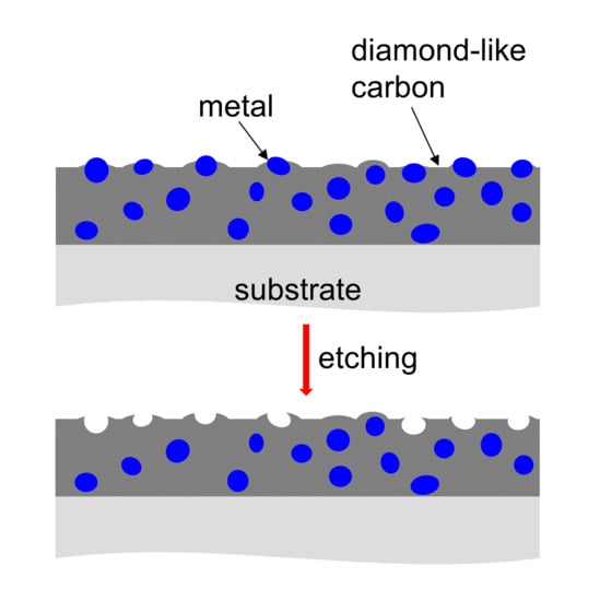
1. Introduction
Diamond-like carbon (DLC) films combine a number of advantageous properties, such as chemical inertness, low wear and friction coefficient, high hardness, corrosion resistance and biocompatibility [1,2]. Furthermore, DLC films tend to be very smooth. Thin DLC films deposited on a featureless substrate, for instance a commercial polished silicon wafer, can exhibit the same average roughness as the substrate [3,4]. On substrates with a moderate roughness, the film surface smoothens as the DLC film grows [5]. In some applications, e.g. the coating of medical implants, a higher surface roughness is desirable, however, because a rough surface promotes cell adhesion [6]. Different cell types favor specific roughness ranges, i.e. the roughness has to be optimized in this regard [7]. In tribological applications that involve liquid lubricants, surface cavities can entrap lubricant, thereby enhancing lubrication [8].
Several approaches have been utilized so far to prepare a DLC film with an inherent nanostructure. DLC deposition on an already structured surface shifts the task of structuring to the substrate. However, with mechanical and simple chemical methods it is difficult to produce a defined roughness [9]. When using a structured substrate, it has to be ensured that a homogeneous deposition can be accomplished. Thicker films will decrease the roughness, as mentioned above. Another approach is the DLC deposition on a partially masked surface. Metallic masks [10,11] and powder particles [12] have been used in this context to prevent localized deposition on the substrate. Especially with masks, only a coarse patterning with dimensions of several tens of µm is achievable. Another possibility is the subsequent structuring of an initially smooth DLC film. If the partial, laterally resolved removal of the film involves focused beams, e.g., one [13] or several laser beams [14,15] or an ion beam [16], the process is slow and costly. In summary, these techniques either produce surface structures with dimensions in the µm range or they are not suitable for the treatment of large areas.
Porous carbon can be produced by various means. The techniques using high-temperature treatment of an organic precursor [17,18] are not suitable for every substrate, though. Bouts et al. [19] presented a concept based on the removal of copper from a copper-containing DLC film. This is the inversion of a technique described before, which dry etched Ag-DLC films with CF4/O2 to reveal the embedded Ag particles [20]. Metal particles in a DLC film form clusters, with their size and distance depending on the metal content. The particle (cluster) size rarely exceeds 10 nm for a metal content of a few ten percent [21]. If the substrate contains percolated nanoparticles (as is the case for Cu concentrations above 60 at.% [19]), etching will result in sponge-like carbon thin films. Etching of non-percolated nanoparticles will lead to a roughening of the surface. The etching or dealloying technique is either limited to pore sizes of up to about 10 nm or a porous structure is produced which deteriorates film properties such as corrosion and wear resistance.
The technique presented here uses larger metal clusters. For a few metals, such as silver [22,23], the metal particles in the surface of a metal-DLC film can be considerably larger than the 10 nm mentioned above. Thus, the holes produced by etching will be correspondingly larger. To demonstrate the feasibility of this approach, not silver- but zinc-containing DLC (Zn-DLC) films were used. With zinc, the electrical conductivity of a DLC film can be increased [24,25] as well as its adhesion [24]. Zinc is biocompatible [26] and biodegradable [27] and thus suitable to be used in coatings of medical implants. Additionally, when preparing Zn-DLC films by plasma source ion implantation and deposition (PSII) [28], the zinc particles within the surface of the DLC film tend to have a diameter of several ten nm, even with average Zn contents as low as 9.6 at.% [29].
2. Materials and Methods
The samples were prepared on a silicon substrate. Pieces with an edge length of 15–20 mm were cut from a commercial silicon wafer (CZ grown, single side polished, <100> orientation, P type (boron doped)) and fixed to a sample holder with 100 mm diameter by small screws. The sample holder was attached to a high voltage feedthrough in a vacuum chamber. The base pressure of the system was 3 × 10⁻⁵ Pa.
The Zn-DLC films were prepared by combining radio frequency magnetron sputtering and a PSII process. Ethylene (C2H4, 99.9%) was used as precursor and thus as carbon source. Ionization of the precursor was achieved by applying a pulsed high voltage of −10 kV (10 µs pulse length with a repetition rate of 1 kHz) to the sample holder. The Zn target (99.99%) was sputtered by argon (99.999%, flow rate of 20 sccm). The zinc content of the samples was altered by changing the C2H4 flow. For the first sample, the flow was 0.75 sccm, for the second one 0.5 sccm. The pressure during the deposition was 0.7 Pa, the sputter power was 45 W, the deposition time 30 and 23 min, respectively. Before deposition, the sputter source was run for 10 min with a closed shutter using only argon as sputter gas to clean the Zn target. The distance of the sample holder to the sputter target was about 100 mm.
The Zn content of the as-prepared samples was determined by X-ray photoelectron spectroscopy (XPS, Shimadzu ESCA, Tokyo, Japan), using an Mg Kα X-ray beam. Depth profiles of the samples (as prepared) were recorded using a 2 keV Ar ion beam. Additional depth profiles of the as prepared and of the etched samples were recorded by secondary ion mass spectrometry (SIMS, Cameca ims 5f, Gennevilliers, France) with a 2.5 keV O2+ ion beam, recording positive secondary ions. The surface morphology was characterized by scanning electron microscopy (SEM, FEI Quanta 200F, Hillsboro, OR, USA, Philips XL 30 FEG, Eindhoven, The Netherlands, and Jeol JSM 6400, Tokyo, Japan, SE images) and atomic force microscopy (AFM, Asylum Research Cypher, Santa Barbara, CA, USA, tapping mode). The film thickness was determined by profilometry (Bruker Dektak Advanced XT, Karlsruhe, Germany), measuring the transition from a coated to an uncoated area of the sample.
For chemical etching, the samples were immersed for 20 s into a HNO3:H2O solution (ratio 1:1), which was heated to 60 °C. Afterwards, the samples were rinsed with deionized water and dried under a stream of hot air.
3. Results
The sample with a lower Zn content has 9.6 at.% Zn, 3 at.% oxygen and a film thickness of about 515 nm. It shows mostly separate particles within its surface. The Zn particles have a width of about 100–200 nm, see Figure 1a. Some of them formed interconnected structures of about 1000 nm length. That the particles extend below the carbon surface can be seen when etching the sample. In Figure 1b an SEM image of the etched surface is shown. The brighter structures associated with Zn have gone and, instead, holes are present, whose dimensions correlate with those of the particles in Figure 1a. In Figure 1b, the edges of the holes appear brighter. A small ridge, as seen in the line scan from an AFM measurement, Figure 1c, surrounds each hole. This ridge is about 20 nm high. The hole has a width of about 95 nm on the level of the surface. It narrows with increasing depth and has a total depth of about 90 nm.
In a cross-sectional SEM image, Figure 2a, the Zn particles on the top of the film are visible. After etching, the Zn particles are removed from the surface, see the indicated voids in Figure 2b. The film itself as seen from the side does not look porous, i.e., the etching did not affect areas further below the surface. (The film in Figure 2b gives the impression of having a larger thickness because the film peeled off somewhat when breaking the substrate.)
The lower Zn content of the surface after etching is also obvious in SIMS depth profiles of the samples, see Figure 3 (note the logarithmic scale of the y-axis). The substrate position is reached after a lower sputtering time in the profiles of the etched samples, indicating that the film thickness was reduced by the etching process. The Zn intensity at the start of the profiles of the etched samples is reduced, but it is not zero, even though in Figure 1b all of the Zn seems to be removed from the surface. As the instrument used for depth profiling was a magnetic sector field mass spectrometer, it recorded the different elements sequentially, i.e., the first data point for Zn represents the situation after several seconds of sputtering with primary ions. Additionally, Zn is only removed in the chemical etching process where it is directly accessible by the etchant. Zn particles in the film that are very close to the surface but do not penetrate it remain in the sample. When starting to remove the surface of the sample by sputtering during the depth profiling, those Zn particles very close to the surface cause the Zn intensity at the start of the depth profile. The reduced Zn content after etching is not only found at the start of the profile but throughout the film. This is related to the influence of particles during a depth profile. The distribution of the Zn is laterally inhomogeneous, as seen in Figure 1a. During the depth profile, it takes some time to remove the particles by sputtering during the analysis. Furthermore, due to different sputter yields and impact angles of the primary ions, a roughening of the surface during the profiling occurs. As a result, signals from different depths are collected at the same sputtering time.
The sample with the higher Zn content has 38.9 at.% Zn, 6.5 at.% oxygen and a thickness of 190 nm. It shows a more network-like arrangement of intertwined Zn particles within the surface in the as-prepared state, see Figure 4a. In Figure 4b an image of the same sample, as prepared, is presented with a higher magnification. Just as with the sample with the lower Zn content, the Zn particles are removed from the surface by the etching process. The remaining surface consists of the nanostructured carbon skeleton and shows an inherent roughness, see Figure 4c. Figure 4d shows the corresponding AFM image of the etched sample. The height differences on the surface after etching amount to several ten nm, reaching 100 nm in some places. The average roughness Ra of the surface is 9.2 nm.
4. Discussion
The feasibility of the two-step approach, comprising the preparation of a zinc-containing DLC film and the removal of the zinc from the film surface by chemical etching, was demonstrated. A DLC film surface with a three-dimensional structure was obtained, whose dimensions are predetermined by the size and distribution of the Zn particles within the surface. Zn particles in the surface of a DLC film tend to be bigger (with a size of at least about 100 nm diameter) than those of most other metal particles (not more than 10 nm diameter) as well as bigger than the Zn particles within the film. Thus, the dimensions of the produced surface structures are, accordingly, larger. The Zn content determines the degree of interconnection of the Zn particles within the surface and thereby the resulting surface structure. Zn contents lower than 10 at.% (9.6 at.% for the sample investigated here) produce a majority of separate holes. Higher Zn contents would lead to longer or more interconnected particles, resulting in holes up to about 1 µm in length. When all “holes” are connected (at 38.9 at.% Zn and above), a rough surface results.
While a large porosity of the film can be achieved by etching of a Cu-DLC film with percolated Cu particles, the resulting film is sponge-like, i.e., it is not suitable for applications that require a certain wear resistance, for instance. With the approach presented here, a continuous DLC film remains on the substrate as the etching only removes zinc particles at the surface. Even for preparation conditions that produce large Zn concentrations of nearly 40 at.% at the surface, the Zn particles are not percolated throughout the film. As a consequence, only the surface of the sample is affected by the etching.
This process involves preparation techniques that are suitable for the treatment of large-scale substrates. Sputtering as well as PSII are mature techniques that can easily be scaled up. The method presented here also has some potential for three-dimensional coating of non-flat samples. While PSII is generally a suitable technique for 3D coating [30], magnetron sputtering is more of a directional technique. However, if the metal were provided in ionized form, e.g., by a vacuum arc ion source [31], those limits could be overcome.
A potential drawback of the approach presented here is that the metal in the DLC film changes the properties of the whole film [32], such as its hardness. Depending on the application, this can be a disadvantage. To avoid this, at least to some degree, a possible variation could be to confine the metal to the surface region. If the metal is added only in the last stages of the deposition, most of the film still has the properties of the undoped DLC film.
5. Conclusions
Nanostructured surfaces of DLC films with surface morphologies with dimensions of 100 nm and above can be produced by surface removal of zinc particles from a zinc-containing DLC film. Depending on the zinc content, two distinct surface structures can be realized: mostly separate holes in an otherwise flat surface (using zinc contents of not more than 10 at.% as otherwise more and more particles tend to interconnect), and a rough surface (if most of the surface is covered by zinc-containing particles in the as prepared state, i.e., before etching, as is the case for zinc concentrations of 38.9 at.% and above). The surface structures produced have dimensions in between those that are feasible by etching Cu-DLC films and by using masked deposition, respectively. Lower parts of the film are not influenced by the etching and a compact film (except for the holes in the surface region) remains on the substrate.
6. Patents
A patent application (DE 102017121684.7) was submitted to the German patent office.
Author Contributions
Conceptualization, R.H. and S.F.; Validation, R.H., S.F., B.R., C.D. and K.B.; Investigation, R.H., S.F., B.R., C.D. and K.B.; Resources, K.B. and W.E.; Data Curation, S.F.; Writing—Original Draft Preparation, S.F.; Writing—Review and Editing, R.H.; Visualization, R.H., S.F., B.R., C.D. and K.B.; Supervision, W.E.
Funding
This research received no external funding.
Acknowledgments
The help of Brunhilde Thybusch and Torsten Walbert from Technische Universität Darmstadt is gratefully acknowledged.
Conflicts of Interest
The authors declare no conflict of interest.
References
- Robertson, J. Diamond-like amorphous carbon. Mater. Sci. Eng. R 2002, 37, 129–281. [Google Scholar] [CrossRef] [Green Version]
- Hauert, R. A review of modified DLC coatings for biological applications. Diamond Relat. Mater. 2003, 12, 583–589. [Google Scholar] [CrossRef]
- Peng, X.L.; Barber, Z.H.; Clyne, T.W. Surface roughness of diamond-like carbon films prepared using various techniques. Surf. Coat. Technol. 2001, 138, 23–32. [Google Scholar] [CrossRef]
- Datta, J.; Ray, N.R.; Sen, P.; Biswas, H.S.; Vogler, E.A. Structure of hydrogenated diamond like carbon by Micro-Raman spectroscopy. Mater. Lett. 2012, 71, 131–133. [Google Scholar] [CrossRef]
- Maharizi, M.; Peleg, D.; Seidman, A.; Croitoru, N. Influence of substrate and film thickness on the morphology and diamond bond formation during the growth of amorphous diamond-like carbon (DLC) films. J. Optoelectron. Adv. Mater. 1999, 1, 65–68. [Google Scholar]
- Ghosh, S.; Xiong, G.; Fisher, T.S.; Han, B. Guidance of cell adhesion and migration by graphitic nanopetals on carbon fibers. Mater. Lett. 2016, 184, 211–215. [Google Scholar] [CrossRef]
- Cohen, A.; Liu-Synder, P.; Storey, D.; Webster, T.J. Decreased fibroblast and increased osteoblast functions on ionic plasma deposited nanostructured Ti coatings. Nanoscale Res. Lett. 2007, 2, 385. [Google Scholar] [CrossRef]
- Gerbig, Y.B.; Ahmed, S.U.; Chetwynd, D.G.; Haefke, H. Topography-related effects on the lubrication of nanostructured hard surfaces. Tribol. Int. 2006, 39, 945–952. [Google Scholar] [CrossRef]
- Anil, S.; Anand, P.S.; Alghamdi, H.; Jansen, J.A. Dental implant surface enhancement and osseointegration. In Implant Dentistry-A Rapidly Evolving Practice; Turkyilmaz, I., Ed.; InTech: London, UK, 2011; pp. 83–110. [Google Scholar]
- Basnyat, P.; Luster, B.; Muratore, C.; Voevodin, A.A.; Haasch, R.; Zakeri, R.; Kohli, P.; Aouadi, S.M. Surface texturing for adaptive solid lubrication. Surf. Coat. Technol. 2008, 203, 73–79. [Google Scholar] [CrossRef]
- Enomoto, T.; Sugihara, T. Improving anti-adhesive properties of cutting tool surfaces by nano-/micro-textures. CIRP Ann. 2010, 59, 597–600. [Google Scholar] [CrossRef]
- Koskinen, J.; Tapper, U.; Andersson, P.; Varjus, S.; Kolehmainen, J.; Tervakangas, S.; Buss, W. Friction reduction by texturing of DLC coatings sliding against steel under oil lubrication. Surf. Coat. Technol. 2010, 204, 3794–3797. [Google Scholar] [CrossRef]
- Chouquet, C.; Gavillet, J.; Ducros, C.; Sanchette, F. Effect of DLC surface texturing on friction and wear during lubricated sliding. Mater. Chem. Phys. 2010, 123, 367–371. [Google Scholar] [CrossRef]
- Marczak, J.; Kusinski, J.; Major, R.; Rycyk, A.; Sarzynski, A.; Strzelec, M.; Czyz, K. Laser interference patterning of diamond-like carbon layers for directed migration and growth of smooth muscle cell depositions. Opt. Appl. 2014, 44, 575–586. [Google Scholar]
- Czyż, K.; Marczak, J.; Major, R.; Mzyk, A.; Rycyk, A.; Sarzyński, A.; Strzelec, M. Selected laser methods for surface structuring of biocompatible diamond-like carbon layers. Diamond Relat. Mater. 2016, 67, 26–40. [Google Scholar] [CrossRef]
- McKenzie, W.; Pethica, J.; Cross, G. A direct-write, resistless hard mask for rapid nanoscale patterning of diamond. Diamond Relat. Mater. 2011, 20, 707–710. [Google Scholar] [CrossRef] [Green Version]
- Peng, Y.; Burtovyy, R.; Yang, Y.; Urban, M.W.; Kennedy, M.S.; Kornev, K.G.; Bordia, R.; Luzinov, I. Towards scalable fabrication of ultrasmooth and porous thin carbon films. Carbon 2016, 96, 184–195. [Google Scholar] [CrossRef]
- Baena-Moncada, A.M.; Planes, G.A.; Moreno, M.S.; Barbero, C.A. A novel method to produce a hierarchical porous carbon as a conductive support of PtRu particles. Effect on CO and methanol electrooxidation. J. Power Sources 2013, 221, 42–48. [Google Scholar] [CrossRef]
- Bouts, N.; El Mel, A.A.; Angleraud, B.; Tessier, P.Y. Sponge-like carbon thin films: The dealloying concept applied to copper/carbon nanocomposite. Carbon 2015, 83, 250–261. [Google Scholar] [CrossRef]
- Tamulevičius, T.; Tamulevičienė, A.; Virganavičius, D.; Vasiliauskas, A.; Kopustinskas, V.; Meškinis, Š.; Tamulevičius, S. Structuring of DLC:Ag nanocomposite thin films employing plasma chemical etching and ion sputtering. Nucl. Instrum. Methods Phys. Res. Sect. B 2014, 341, 1–6. [Google Scholar] [CrossRef]
- Schiffmann, K.I.; Fryda, M.; Goerigk, G.; Lauer, R.; Hinze, P.; Bulack, A. Sizes and distances of metal clusters in Au-, Pt-, W- and Fe-containing diamond-like carbon hard coatings: A comparative study by small angle X-ray scattering, wide angle X-ray diffraction, transmission electron microscopy and scanning tunnelling microscopy. Thin Solid Films 1999, 347, 60–71. [Google Scholar]
- Cloutier, M.; Turgeon, S.; Busby, Y.; Tatoulian, M.; Pireaux, J.J.; Mantovani, D. Controlled distribution and clustering of silver in Ag-DLC nanocomposite coatings using a hybrid plasma approach. ACS Appl. Mater. Interfaces 2016, 8, 21020–21027. [Google Scholar] [CrossRef] [PubMed]
- Wang, L.J.; Zhang, F.; Fong, A.; Lai, K.M.; Shum, P.W.; Zhou, Z.F.; Gao, Z.F.; Fu, T. Effects of silver segregation on sputter deposited antibacterial silver-containing diamond-like carbon films. Thin Solid Films 2018, 650, 58–64. [Google Scholar] [CrossRef]
- Foong, Y.M.; Koh, A.T.T.; Lim, S.R.; Hsieh, J.; Chua, D.H.C. Materials properties of ZnO/diamond-like carbon (DLC) nanocomposite fabricated with different source of targets. Diamond Relat. Mater. 2012, 25, 103–110. [Google Scholar] [CrossRef]
- Das, A.K.; Hatada, R.; Ensinger, W.; Flege, S.; Baba, K.; Meikap, A.K. Dielectric constant, AC conductivity and impedance spectroscopy of zinc-containing diamond-like carbon film UV photodetector. J. Alloy. Compd. 2018, 758, 194–205. [Google Scholar] [CrossRef]
- Bowen, P.K.; Guillory, R.J.; Shearier, E.R.; Seitz, J.M.; Drelich, J.; Bocks, M.; Zhao, F.; Goldman, J. Metallic zinc exhibits optimal biocompatibility for bioabsorbable endovascular stents. Mater. Sci. Eng. C 2015, 56, 467–472. [Google Scholar] [CrossRef] [Green Version]
- Seitz, J.M.; Durisin, M.; Goldman, J.; Drelich, J.W. Recent advances in biodegradable metals for medical sutures: A critical review. Adv. Healthc. Mater. 2015, 4, 1915–1936. [Google Scholar] [CrossRef]
- Conrad, J.R.; Radtke, J.L.; Dodd, R.A.; Worzala, F.J.; Tran, N.C. Plasma source ion-implantation technique for surface modification of materials. J. Appl. Phys. 1987, 62, 4591–4596. [Google Scholar] [CrossRef]
- Hatada, R.; Flege, S.; Rimmler, B.; Ensinger, W.; Baba, K. Properties of zinc-containing diamond-like carbon films prepared by plasma source ion implantation. Trans. Mater. Res. Soc. Jpn 2017, 42, 37–40. [Google Scholar] [CrossRef]
- Anders, A. Handbook of Plasma Immersion Ion Implantation and Deposition; John Wiley & Sons: New York, NY, USA, 2000. [Google Scholar]
- Anders, A. Cathodic Arcs, Springer Series on Atomic, Optical, and Plasma Physics; Springer: New York, NY, USA, 2008; Volume 50. [Google Scholar]
- Sánchez-López, J.C.; Fernández, A. Doping and alloying effects on DLC coatings. In Tribology of Diamond-like Carbon Films; Springer: New York, NY, USA, 2008; pp. 311–338. [Google Scholar]
Figure 1.
Zn-diamond-like carbon (DLC) sample with about 10 at.% Zn: (a) scanning electron microscope (SEM) image of the sample as prepared; (b) SEM image of the sample after etching; (c) atomic force microscopy (AFM) line scan of a hole in the etched sample.
Figure 1.
Zn-diamond-like carbon (DLC) sample with about 10 at.% Zn: (a) scanning electron microscope (SEM) image of the sample as prepared; (b) SEM image of the sample after etching; (c) atomic force microscopy (AFM) line scan of a hole in the etched sample.

Figure 2.
Cross-sectional SEM images of the sample with 9.6 at.% Zn on the surface: (a) as prepared; (b) after etching.
Figure 2.
Cross-sectional SEM images of the sample with 9.6 at.% Zn on the surface: (a) as prepared; (b) after etching.

Figure 3.
Secondary ion mass spectrometry (SIMS) depth profiles of Zn-DLC samples, showing the signals 12C, 30Si and 64Zn (a) 9.6 at.% Zn, as prepared; (b) 9.6 at.% Zn, etched; (c) 38.9 at.% Zn, as prepared; (d) 38.9 at.% Zn, etched.
Figure 3.
Secondary ion mass spectrometry (SIMS) depth profiles of Zn-DLC samples, showing the signals 12C, 30Si and 64Zn (a) 9.6 at.% Zn, as prepared; (b) 9.6 at.% Zn, etched; (c) 38.9 at.% Zn, as prepared; (d) 38.9 at.% Zn, etched.

Figure 4.
Zn-DLC sample with 38.9 at.% Zn: (a) SEM image of the sample as prepared; (b) SEM image of the sample as prepared, with higher magnification; (c) SEM image of the sample after etching; (d) AFM image of the etched surface.
Figure 4.
Zn-DLC sample with 38.9 at.% Zn: (a) SEM image of the sample as prepared; (b) SEM image of the sample as prepared, with higher magnification; (c) SEM image of the sample after etching; (d) AFM image of the etched surface.


© 2019 by the authors. Licensee MDPI, Basel, Switzerland. This article is an open access article distributed under the terms and conditions of the Creative Commons Attribution (CC BY) license (http://creativecommons.org/licenses/by/4.0/).
Share and Cite
MDPI and ACS Style
Hatada, R.; Flege, S.; Rimmler, B.; Dietz, C.; Ensinger, W.; Baba, K. Surface Structuring of Diamond-Like Carbon Films by Chemical Etching of Zinc Inclusions. Coatings 2019, 9, 125. https://doi.org/10.3390/coatings9020125
AMA Style
Hatada R, Flege S, Rimmler B, Dietz C, Ensinger W, Baba K. Surface Structuring of Diamond-Like Carbon Films by Chemical Etching of Zinc Inclusions. Coatings. 2019; 9(2):125. https://doi.org/10.3390/coatings9020125
Chicago/Turabian StyleHatada, Ruriko, Stefan Flege, Berthold Rimmler, Christian Dietz, Wolfgang Ensinger, and Koumei Baba. 2019. "Surface Structuring of Diamond-Like Carbon Films by Chemical Etching of Zinc Inclusions" Coatings 9, no. 2: 125. https://doi.org/10.3390/coatings9020125
Note that from the first issue of 2016, this journal uses article numbers instead of page numbers. See further details here.