Ångström-Scale, Atomically Thin 2D Materials for Corrosion Mitigation and Passivation


Department of Mechanical Engineering, University of South Florida, 4202 E. Fowler Avenue, Tampa, FL 33620, USA
*
Author to whom correspondence should be addressed.
Coatings 2019, 9(2), 133; https://doi.org/10.3390/coatings9020133
Submission received: 11 December 2018
/
Revised: 11 February 2019
/
Accepted: 11 February 2019
/
Published: 19 February 2019
(This article belongs to the Special Issue Corrosion Characterization and Surface Analysis of Metallic Materials)
Abstract
:Metal deterioration via corrosion is a ubiquitous and persistent problem. Ångström-scale, atomically thin 2D materials are promising candidates for effective, robust, and economical corrosion passivation coatings due to their ultimate thinness and excellent mechanical and electrical properties. This review focuses on elucidating the mechanism of 2D materials in corrosion mitigation and passivation related to their physicochemical properties and variations, such as defects, out-of-plane deformations, interfacial states, temporal and thickness variations, etc. In addition, this review discusses recent progress and developments of 2D material coatings for corrosion mitigation and passivation as well as the significant challenges to overcome in the future.
1. Introduction
Corrosion is an electrochemical process of gradual material dissolution through a redox reaction between material and diverse oxidizing species. A notable portion of the periodic table comprises of metals upon which modern society is immensely dependent. Therefore, the natural tendency of metal deterioration is a prevalent and intrinsic material problem is ubiquitous in every industry (e.g., automotive, marine, infrastructures) and introduces material failure risks and public health and safety hazards (e.g., Flint water crisis) [1]. According to National Association of Corrosion Engineers (NACE), the overall global cost of corrosion exceeds $2.5 trillion/year [2]. Factoring in the expense of conventional prevention methods, the entire cost accounts for nearly 4% of GDP for developed nations, not to mention the concomitant environmental impacts associated [3]. Consequently, even minor improvements in mitigating corrosion would result in enormous advancements for the global economy, making extensive research and application towards novel corrosion mitigation strategies a pressing priority.
The intrinsic properties of a material and its surrounding environment dictate the corrosion mechanism and rate. This corrosion rate is directly proportional to the degree of inherent environment corrosivity and inversely proportional to the corrosion resistance of a metal. Typically, corrosion mitigation and passivation of metal involve several techniques such as cathodic protection, alloying the target metal, and surface coating, etc.
There are two general techniques to achieve cathodic protection of metals: a sacrificial anode and an impressed current. A sacrificial anode, being more electrochemically active (in terms of galvanic potential) than the metal to be protected, oxidizes to provide cathodic protection to the metal [4]. Often, difficulties in installation and access present barriers for the use of sacrificial anodes. On a separate note, impressed current cathodic protection (ICCP) uses a direct current (DC) power source that supplies electrons from the anode to the metal (cathode). However, ICCP has limitations such as non-uniform current distribution, spark hazards, and hydrogen embrittlement [5,6].
Many metals (e.g., Al, Mg) form protective passive films in the presence of oxidizing species. The oxidized surface films, with their atomic scale thickness, have the ability to suppress further metallic corrosion [7]. However, halides and other anions can penetrate the passive films and initiate localized pitting or crevice corrosion [8]. Alloying metals can promote, strong and enduring passive film formation [9]. However, alloying changes the chemical composition and metal properties, which may not be cost effective or feasible for particular applications.
Surface coating is a versatile corrosion mitigation and passivation strategy by isolating the susceptible metallic surfaces from the oxidizing species. A variety of corrosion passivation coatings for metallic surfaces are abundant such as individual or combination of organic [10], multilayer [11,12,13], polymer coatings [14], nitride-based coatings [15,16]. However, these coatings have their respective inherent advantages and limitations. Organic and polymer coatings have a relatively large thickness (up to several microns), which could adversely affect thermal and electrical conductivity as well as the component dimensionality [17]. Many traditional polymer coatings are susceptible to microbial corrosion, high-temperature degradation, and have inherent porosity [14,18].
Comparatively, impermeable atomically thin layered 2D materials are ideal candidates for surface coatings against corrosion. Much debate was present on the structural stability of crystalline 2D materials under atmospheric condition until the experimental isolation of monolayer graphene—a hexagonal lattice of sp2 hybridized C–C bonds [19]. Over the past decade, a plethora of analogous 2D materials (e.g., hexagonal boron nitride (hBN), transition metal chalcogenides (TMDCs), MXenes), have been discovered and made possible by significant progress in various synthesis methods (Figure 1) [20]. The family of 2D material exhibits a wide range of novel mechanical and electrical properties such as large surface area [21], impermeability [22], bandgap tunability [23], thermal stability [24], and wetting “translucency” [25,26,27]. The most obvious advantage of 2D materials for corrosion mitigation and passivation is their impermeability to even the smallest atoms, such as helium, which is unprecedented in conventional materials. Additionally, ultra-thin 2D materials have the additional advantage of being nearly imperceivable. Overall, 2D materials have numerous advantageous properties, which make them suitable for atomically thin anti-corrosive coatings.
The intricate physical (e.g., impermeability, morphology) and chemical (e.g., redox potential) aspects of 2D materials dictate their surface corrosion passivation mechanisms. Recent studies of 2D materials in the context of anti-corrosion have focused on graphene [28,29,30] and graphene derivatives (graphene oxide (GO) [31,32], reduced graphene oxide (rGO)), hBN [33], and silicates such as mica and talc [34]. In this featured review article, our focus is to elucidate and discuss the recent progress and development of 2D material coatings for corrosion mitigation and passivation in different sectors. We then briefly explore the various complementary corrosion characterization techniques and the effect of many unique physical and chemical aspects of 2D material. Furthermore, we postulate the future prospects of 2D coatings.
2. Application of 2D Corrosion Passivation Coatings
Corrosion passivation coatings are used ubiquitously to suppress the detrimental effects of corrosion (i.e., material loss and subsequent risk of mechanical/material failure). Since their monolayer isolation in 2004, atomically thin 2D materials are gaining traction as potential corrosion mitigation and passivation coatings. Unlike graphene and hBN, many 2D materials have not been explored extensively as anti-corrosive coatings due to several limitations. The structural instability of 2D materials in various aggressive environmental conditions and the degree of influence of specific environmental constituents limit the application of 2D materials in passivation coatings. For example, black phosphorus (bP) is not suitable for use in corrosion passivation coatings due to its self-detrimental effect on temperature as well as time. Atomically thin bP has an orthorhombic lattice structure with a lone pair of sp3 elections, which makes it unstable under ambient temperature and ultimately vulnerable to oxidation. In fact, graphene and hBN are required to protect bP in an atmospheric condition [35,36]. In addition, researchers have shown that water, rather than oxygen, plays a primary role in the instability of MXenes (Ti3C2Tx and Ti2C2Tx) in aqueous colloids, thus, making water more harmful for MXenes [37].
Much literature has been devoted to understanding the physicochemical properties of 2D materials with regards to corrosion mitigation and passivation coatings, as well as pointing out the feasible applications in the industrial scale. In this section, a brief overview of the current and potential applications of 2D material coatings is provided.
2.1. Biomedical
In the biomedical field, metals and metallic alloys are used ubiquitously for various purposes such as dental amalgam, prostheses, and stents. These are subjected to corrosion due to the presence of biological fluids containing electrolytes, acids, bacteria, and enzymes. Subsequently, corrosion produces metal debris or soluble metallic ions, which creates long-term detrimental effects on the human body such as metallosis, toxic, or allergic reactions [38,39,40]. It should be noted that this type of coating has to be compatible with the human body, for which inert 2D coatings (i.e., graphene and hBN) are suitable candidates [38,41]. For example, graphene coatings exhibited a reduced corrosion rate of Cu metal in several biological solutions such as fetal bovine serum (FBS), Hank’s balanced salt solution (HBSS), phosphate buffered saline (PBS), and cell culture media [38].
For temporary bioimplants (i.e., pins, screws), a second surgery is required to remove the metallic (i.e., titanium alloys, stainless steels) parts. However, Mg is a bioresorbable metal that has properties similar to human bones that can be used as a replacement [42]. Through conjugation with biocompatible 2D material coatings (e.g., hBN-silane 2D composite), the precise resorption rate of Mg can be engineered to time the Mg temporary implant service life [41].
2.2. Petroleum Industry
The petroleum industry has used 2D materials extensively used for various purposes such as lubrication, demulsification, drilling, and, most importantly, anti-corrosive coatings [43]. Metals that are used in various heavy equipment in the petroleum industry can potentially be passivated using 2D materials. For example, a composite thin film (≤200 nm) consisting stainless steel/rGO nanoplatelets and alternating nanolayers of two different ceramic materials (i.e., alumina and titania) have exhibited lower porosity compared to neat alumina/titania, thus higher corrosion passivation of the underlying steel [44]. This type of barrier can also be fabricated using graphene flakes or an ink coating consisting of GO and oil [45,46].
Moreover, petroleum production well exhibits a severe issue of microbially induced corrosion (MIC) [43]. MIC is a specific type of corrosion where metal deterioration occurs due to microorganisms’ metabolic products (i.e., sulfate-reducing bacteria (SRB), sulfur-oxidizing bacteria). Some 2D materials such as graphene, GO, and hBN have exhibited good performance as MIC passivation coating of metals as well as antibacterial coatings [47,48,49,50,51,52,53,54].
2.3. Power Plant
The build-up of corrosion products can deteriorate the quality of heat exchange surfaces, reducing the thermal conductivity, media flow rate, and longevity. The use of 2D materials as candidates for corrosion and fouling passivation of metal in different heat exchanger environments (e.g., turbulent flow boiling condition, the repetitive bursting force of bubble) is also promising [55].
In the context of nuclear-pressurized water reactors, 2D material coatings have been shown to provide higher corrosion passivation compared to the conventional coatings such as organic, inorganic, or polymer coatings in the high-temperature environment of PWR. For example, graphene has been employed as an oxidation barrier for Ni under high-temperature condition, allowing boric acid in the deaerated primary water to only create a trace amount of nickel oxide [56].
2.4. Marine Environment
Corrosion has a disastrous impact on naval vehicles due to the omnipresence of salt in the marine environment. Both intrinsic and composite forms of coatings have been put to test for evaluating the corrosion performance of the 2D materials in seawater. In fact, most corrosion research surrounding 2D materials has been carried out in simulated seawater containing 3.5 wt% of NaCl, which mimics a marine environment. For example, a layered graphene coating on mild steel has been shown to reduce the corrosion rate due to its barrier effect in seawater (Figure 2) [57].
2.5. Aerospace Vehicles
Low earth orbit (LEO) contains an abundance of atomic oxygen (oxygen radicals) generated from atmospheric photodecomposition. Spacecraft in LEO have speeds of up to 8 km/s which yields a collision energy of atomic oxygen (AO) of about 5 eV with high atomic incoming flux (1014 to 1015 atoms/cm2) [58]. Coatings of 2D material can be applied to passivate spacecraft in LEO [59]. For example, the polymer parts of a spacecraft can be passivated from atomic oxygen using boron nitride nanosheet (BNNS) coatings (Figure 3). The BNNS flakes reduce corrosion of nylon by blocking and physio absorbing the oxidizing species [60].
In addition, 2D materials have immense potential in aviation technology as a corrosion passivation coating. For example, graphene nanoflakes exhibited successful corrosion reduction of aircraft when used as filler material in water-based epoxy resin coating [61].
3. Corrosion Characterization Techniques
Spontaneous corrosion results from Gibbs free energy (ΔG) change of an electrochemical system towards equilibrium (ΔG = 0). Gibbs free energy can be described as ΔG = −nFE, where n is the number of electrons, E is electrochemical cell potential (Ecathode − Eanode), F is Faraday constant (96,500 Coulomb/mole). A certain redox reaction is energetically favorable (i.e., spontaneity of electrochemical cell) if ΔG < 0 and E > 0. Redox reactions generate a flow of electrons between the cathode and anode. In an aqueous environment, the anodic atom loses electrons and oxidizes (M = Mn+ + ne−, where M denotes the metal or alloy), detaches from the anode and thus deteriorates or corrodes in the process. The free electrons are consumed by the cathodic reaction (i.e., reduction of oxygen, hydrogen, or water) and generate the corrosion current that is typically expressed as current density, Icorr, with a unit of current per unit area of a working electrode [62]. The measurement of Icorr and other associated parameters (e.g., resistance, capacitance) can elucidate the mechanism of corrosion behavior of a certain target metal or coating. Therefore, it is crucial to identify what role each characterization technique plays and how to utilize them to understand the underlying mechanism of corrosion. A brief discussion about different corrosion characterization techniques is presented in this section.
The three-electrode system is used during polarization test where the anode is the working electrode and cathode is the counter electrode, with the presence of an inert, non-participating reference electrode. The relationship between the current and potential for a three-electrode system undergoing an electrochemical reaction can be described by the Butler–Volmer Equation [63]:
where I is the applied current, Ia is anodic current, Ic is the cathodic current, I0 is the exchange current density (when η = 0, Ia = −Ic = I0; i.e., Icorr), T is the absolute temperature in Kelvin (K), R is the universal gas constant, αa is the and αc is the cathodic charge transfer coefficients, and η is the overpotential defined as the difference anodic charge transfer coefficients between applied (E) and corrosion potential (Ecorr) [63]. Kinetically, charge transfer at the electrodes and mass transfer through the electrolyte are the two limiting parameters for the redox reaction rate [62]. Hence, the corrosion current depends on the electrode materials and electrolytes present in the electrochemical setup.
At high overpotentials (either positive or negative), the Butler–Volmer Equation can be simplified as the Tafel Equation [62]:
where β is the Tafel slope, which has two forms: βa (i.e., anodic Tafel slope that is determined at highly positive η when Ia >> Ic) and βc (i.e., cathodic Tafel slope that is determined at highly negative η when Ia << Ic) [64]. The Tafel Equation can be used to determine the corrosion current density.
During a potentiodynamic (PD) test, a voltage is provided as input between the working and reference electrode and a current is measured as output between the working and counter electrode. The input voltage is a dynamic or sweeping which ranges from the cathodic to anodic domain. In addition, this potential range depends on the electrode material. The output graph of the PD test consists of an anodic and a cathodic region and corrosion potential point (Ecorr) at η = 0 (Figure 4a). In the cathodic potential region, the working electrode does not corrode. With increasing potential, corrosion activation occurs after Ecorr, followed by a passive film formation and pitting corrosion at the pitting potential, Epit [65].
Icorr is equivalent to the cathodic and anodic current at open circuit potential. Although Icorr cannot be measured directly, Icorr can be approximated through electrochemical techniques. For example, Ecorr and Icorr can be estimated by performing Tafel extrapolation in the linear cathodic and anodic regions by using the Tafel slopes for anodic (βa) and cathodic (βc) region (Figure 4b) [66].
In addition, a faster and nondestructive linear polarization resistance (LPR) test can be performed to estimate Icorr in the low overpotential region (restricting the applied potential near to Ecorr) using the Stern–Geary Equation [63,67],
Moreover, the estimated value of Icorr can be used to find the amount of material loss (W) and the corrosion rate (CR) through Equations (4) and (5) [62]:
where t is the time, and,
where A is the working electrode surface area and is the material density. The performance of a coating can be interpreted by measuring Icorr through a PD test. For example, the graphene coating on Al decreases the Icorr, indicating corrosion passivation (Figure 4b) [68].
During a corrosion test, when the working electrode is at a fixed cathodic potential, corrosion is suppressed, whereas, at a fixed anodic potential, a passive film forms on the metallic surface. Thus, a potentiostatic (PS) test can be performed at fixed anodic potential to understand the structure and stability of the passive film by measuring the current, I = At−k, where A is a constant based on electrolyte and potential and k is the slope in the logarithmic I vs. logarithmic t graph indicating the passive film compactness factor [9].
Another technique to understand the influence of a coating on the charge transfer kinetics between metal and electrolyte is electrochemical impedance spectroscopy (EIS). EIS can measure the solution resistance (Rs), electric double layer capacitance (Cdl), charge transfer resistance (Rct), pore resistance (Rp), etc. [69]. An anti-corrosive coating should exhibit high (Rct) and low (Cdl) indicating slow charge transfer between metal and electrolyte [70].
Besides the mentioned techniques, further characterization is imperative to identify the 2D material defects and the presence and evolution of the surface corrosion product (i.e., oxides, nitrides, chlorides, sulfides). Table 1 summarizes several techniques, which can assist in the characterization of 2D material/metal systems.
4. Mechanisms of 2D Corrosion Passivation
The mechanisms of 2D corrosion passivation depend on intricate and diverse physical and chemical aspects, which are dependent on each other. In this section, we analyze corrosion passivation of metal via 2D materials from various viewpoints.
4.1. Impermeability
Pristine, defect-free 2D materials are impermeable to small atomic and ionic species, which makes them suitable for corrosion passivation of metal [83]. This impermeability results from the unique lattice structures of 2D materials, which has small geometric pore sizes. For example, graphene has a nonpolar C–C sigma (σ) bond length is 1.42 Å [84]. The delocalized dense cloud of overlapping π-orbitals generates a barrier, which, factoring in the van der Waals radius of carbon in graphene, forms a geometric pore of size 0.64 Å, which is smaller than even the smallest He atom with a diameter of 2.8 Å (Figure 5a) [83,85]. Analogous to graphene, hBN has a similar atomic structure with a polar B–N sigma (σ) bond length of 1.446 Å [86]. As such, graphene and hBN are both atomically impermeable, a characteristic that plays a key role in corrosion passivation.
In addition, permeance through a 2D material, denoted as Q, can be expressed as [22]:
where C is the particle collision rate, Pr is the diffusion probability, and ΔP is the pressure difference across the membrane. First, for a 2D material, diffusion probability is very low due to the absence of interatomic gaps. In addition, Pr is inversely proportional to the penetration energy barrier (PEB) of molecules. For example, O2, being a diatomic molecule, can have three different geometric orientations when in contact with single-layer graphene (SLG). The three orientations between the axis along oxygen σ bond and graphene plane are (a) perpendicular, (b) parallel, and (c) oblique (Figure 5b). Computational calculation shows that the PEB was larger than 34.3 eV for all three orientations [87]. For hBN, the PEB of O2 is 34.2 eV, which is nearly the same as graphene due to their similarity in lattice structures [88]. In addition, the PEB varies with the molecular size. For example, He atom has a lower PEB than O2 due to its smaller molecular diameter [89]. Similar to O2, however, He molecules do not possess enough kinetic energy to overcome the PEB at room temperature.
The pressure difference, ΔP, across a 2D material can increase the molecular diffusion. Impermeability of continuous and defect-free few-layer graphene (FLG) to various gases (i.e., He, Ar, and air) has been investigated [22]. A continuous graphene sheet was suspended over a microchamber created in a SiO2 substrate (Figure 5c). Graphene was adhering onto the SiO2 through the van der Waals force between the graphene and substrate. The suspended graphene underwent outward and inward balloon shaped deformations due to positive and negative ΔP values, respectively (Figure 5e,f). The deformation size decreases with time due to gas permeation through the substrate walls and the clamped SiO2-graphene interface (Figure 5g). Gas permeation does not occur transversely through the graphene, which was demonstrated by establishing an independent relationship between the gas leakage rate and graphene layer thickness. Thus, the graphene remained impermeable under pressures higher than one atmosphere.
4.2. Defects in 2D Material
The presence of various defects, such as vacancies, ripples, wrinkles, cracks and voids, disrupts the otherwise impermeability of 2D materials, which considerably compromises their capacity for corrosion passivation [90,91,92]. In this section, we review various aforementioned defects, their origins (from the specific growth and/or transfer processes), and their ramifications for corrosion passivation (or lack thereof).
4.2.1. Growth-Induced Defects—Vacancies, Dislocations, Grain boundaries, and Stone–Wales Defects
Various 2D material preparation techniques have been developed, which can be classified generally into two categories: top-down techniques (i.e., exfoliation via mechanical [19,93,94,95], liquid [96,97] or chemical [98,99] means, electro-ablation [100]), and bottom-up techniques (i.e., atomic layer deposition (ALD) [101,102], pulsed laser deposition (PLD) [103,104], chemical vapor deposition (CVD) [105,106]). Typically, exfoliation generates 2D material flakes with small lateral sizes and poor dimensional control. The liquid exfoliation (e.g., sonication assisted liquid exfoliation, wet ball milling) method could induce different kinds of defects in 2D materials. In addition, the defect density of exfoliated 2D materials depends on their precursor (bulk) material quality (e.g., HOPG, kish graphite for graphene exfoliation).
Among the bottom-up techniques, atomic layer deposition of 2D materials has been restricted to TMDCs. Pulse laser deposition of 2D material has an inherent issue of high crystallinity or amorphous nature as well as imprecise control over deposition thickness [107]. On the other hand, CVD is a widely accepted high-temperature, large-scale 2D material growth technique. However, CVD growth of 2D material includes the formation of intrinsic defects such as point defects (i.e., atomic vacancies) and linear defects (i.e., dislocations, grain boundaries) [108].
Atomic vacancies disrupt linear atomic arrangement in 2D materials and create dangling or undercoordinated bonds (Figure 6) [109]. Subsequently, the saturation of dangling bonds by the Jahn–Teller geometric distortion forms different polygons in a 2D material [110]. Experimental studies have reported that Stone–Wales (SW) defect, di-, tetra-, hexa-, and even up to deca-vacancies can be present in 2D materials [89,111,112]. Stone–Wales (SW) defect is a widespread topological defect, which is mostly present in grain boundaries. Unlike an atomic vacancy, a Stone–Wales defect does not occur due to missing atoms from the lattice; rather, it originates from the 90° rotation of π-bonded atomic pairs and consequently forms adjacent heptagons and pentagons. A Stone–Wales defect has low formation energy in graphene, and therefore such defects can easily be observed in graphene [113]. Conversely, contrary to theoretical predictions, Stone–Wales defects have not been found experimentally in hBN [114,115,116,117].
Grain boundaries are linear defects that can form due to the accumulation of dislocations. Polycrystallinity and roughness of a substrate play a key role in 2D material grain boundary formation during CVD growth. Due to the polycrystalline nature of most metallic substrates, many isolated islands of 2D material nucleate individually until they eventually merge and form grain boundaries. Due to the change of atomic arrangement from one grain to another, the grain boundaries contain many types of the aforementioned defects (Figure 7a,b) [118,119]. Analogously, during initial CVD growth period, a polished metallic surface has a lower number of nucleation sites compared to its rougher counterpart. Therefore, a 2D material grown on a polished substrate inherits larger domains with less grain boundary density. For example, it has been demonstrated that graphene/polished Cu has higher corrosion resistance compared to graphene/ground Cu for a short period of time.
Consequently, due to the higher defect density, the local metallic surfaces under the 2D material grain boundaries are susceptible to preferential corrosion. For example, graphene’s exposure to vapor hydrofluoric (VHF) acid has shown that VHF preferentially etches the substrate by diffusing through the grain boundaries [120]. Therefore, metal should desirably be coated with monocrystalline in lieu of polycrystalline 2D materials. The absence of grain boundaries and other defects enhances impermeability and results in a higher degree of suppression of corrosion [121]. Much literature has recently been reported on controlled growth of monocrystalline 2D materials [122,123,124,125,126].
Grain boundary defects, along with atomic vacancies, result in incomplete coverage of the metal by the 2D coating. For example, a total defective area of up to 4% with grain boundary defect sizes of 30–50 Å and atomic vacancies of less than 10 Å has been observed in monolayer CVD-grown graphene [119]. Moreover, besides atomic vacancies, Ångström-scale voids measuring up to 10–150 Å in diameter can be present in 2D materials, which drastically decreases the coating coverage [127]. The PEB of oxidizing species becomes very low due to the presence of vacancies [89,111]. Local density approximation (LDA) calculations have shown that He atoms encounter little resistance during diffusion through vacancies with larger dimensions (i.e., 0.05 eV for deca-vacancy compared to 18.77 eV for pristine graphene). However, for other smaller defects, the PEB is high enough to ensure the impermeability of graphene to oxidizing species.
4.2.2. Transfer-Induced Defects
CVD-grown 2D materials are synthesized on selective low-solubility catalyst substrates such as Cu and Ni. For practical applications, reliable and smooth post-growth handling of 2D materials is crucial to fabricate uniform and defect-minimized coatings onto the target metal, as the inadequate transfer of 2D materials may cause such defects as holes, tears, ruptures, wrinkles. Various transfer techniques have been developed, which can be classified generally into two categories: dry transfer [128] and wet transfer [129,130].
Dry transfer using thermal release tape (TRT) or pressure sensitive adhesive films (PSAFs), is a rapid process but leaves voids and tape residues on the 2D material [131,132]. In addition, during the dry transfer process, pressure is applied to achieve 2D material conformity over a corrugated substrate, and subsequent pressure release causes the formation of wrinkles and bubbles [133].
Wet transfer of 2D materials can be achieved in different ways such as polymer-assisted transfer, bubbling transfer, free-floating transfer. Although widely used and cost-effective, polymer-assisted and bubbling wet transfer techniques generate polymer and etchant contamination, bubbles, cracks due to the use of a handle layer and etchant/electrolyte solutions [132,134]. In addition, the free-floating technique is an easily accessible wet transfer technique, but it is prone to creating high defect density (i.e., voids, cracks) 2D coating and not suitable for large area 2D material transfer [132].
It has been demonstrated that, factoring in the growth-induced defects, transferring a 2D material can further deteriorate the 2D material structure (Figure 8) [18]. For example, researchers have found that as grown graphene on a rough metal substrate, if transferred to a target substrate, provides poor 2D material quality (i.e., higher defect density). This is because graphene grown on the deep trenches of the rough substrate is not compatible with the transfer process and thus creates cracks accordingly. In addition, preexisting growth-induced cracks present in 2D materials can propagate due to wet transfer which adversely affects 2D material impermeability [135].
4.2.3. Galvanic Coupling—A Setback for Conductive/Metallic 2D Materials
Galvanic corrosion is a specific form of electrochemical corrosion that occurs between two electronically coupled dissimilar metals (i.e., cathodic and anodic) with different electromotive or electrochemical corrosion potentials (ECP). The ECP of different materials can be sequentially ordered to form a galvanic series (Figure 9a).
In selecting a 2D anti-corrosive coating, the intrinsic property of the 2D material is critically important to avoid galvanic corrosion. Conductive 2D material coatings with defects form a very proximal galvanic coupling with the underlying metal. For example, graphene is electrochemically noble with a high charge carrier mobility and aids electron movement during redox reactions, thereby, becoming cathodic to common metals (Figure 9b) [70,136]. A small opening in the graphene coating can expose a small underlying metallic (anodic) area to the larger cathodic area. When the ratio between the cathodic (graphene) and anodic (metal) areas of two dissimilar materials becomes high, accelerated localized pitting/galvanic corrosion of the anode exacerbates the material degradation (Figure 9c,d) [137]. Therefore, an imperfect graphene coating can unintentionally worsen the corrosion scenario, whether is in the intrinsic or composite form [138]. For example, graphene creates an adverse effect in its composite form with magnesium alloys (AZ31 and AZ61) due to galvanic coupling [139].
On the contrary, in hBN, the different electronegativity of nitrogen (i.e., 3.04) and boron (i.e., 2.04) atoms create localized π-electrons near nitrogen. Thus, hBN is inherently insulating and does not induce galvanic corrosion. A comparative experimental study between SLG and SL-hBN (i.e., single-layer hBN) on Cu showed that hBN can reduce the galvanic corrosion by nearly 400 times [49]. The galvanic corrosion current density (Ig) and galvanic potential showed a peak during the initial stage of corrosion for SLG (Figure 10a,b). The corrosion current was found to be significantly lower for an SL-hBN coating, indicating lower corrosion (Table 2). In addition, the galvanic potential of Cu/SLG (i.e., −744 mV) is higher than Cu/hBN (i.e., −792 mV), indicating the more cathodic nature exhibited by graphene.
Interestingly, graphene can reduce galvanic corrosion in certain circumstances. In 96.5Sn–3Ag–0.5Cu (SAC) solder, Sn is electrochemically negative compared to the intermetallic compound Ag3Sn, and thus a galvanic cell is formed. Graphene nanosheet (GNS) reinforcement creates an Sn matrix comprising numerous micro galvanic corrosion cell instead of one, thus reduces overall corrosion.
4.2.4. Effect of Ripples and Wrinkles
The flexibility of 2D materials is due to their large surface area and atomically thin nature while being high in-plane strength and stiffness [140,141]. As such, 2D materials have an inherent tendency for out-of-plane deformation such as buckling, ripples, wrinkles.
Ripples can spontaneously form in atomically thin 2D materials due to thermal fluctuation [142]. Thermal energy and delocalized π electron clouds disrupt the bond length symmetry of the 2D material lattice, which leads to out-of-plane deformations to achieve stability [143]. This non-uniformity in bond length forms ripples near the crystallographic defects and edges, which suppresses the planar stress distribution of the 2D material [144]. The size distribution of thermally induced ripples can be estimated by the following Equation [142]:
where L* is the spatial scale of ripple distribution, κ is the bending rigidity, and B is the 2D material bulk modulus. If the temperature, T = 0 K, as can be seen from Equation (7), there will be no out-of-plane deformation [143].
As discussed earlier, flat graphene is impermeable, whereas ripples and wrinkles can facilitate the permeation of oxidizing species. For example, it has been demonstrated that the oxidizing species at room temperature can diffuse to the graphene/Cu interface in either the transverse or the lateral direction along graphene ripples. The graphene coating used for experiment contained negligible defects, thus minimizing the possibility of defect-induced corrosion. Here, the overall PEB values for oxygen transverse diffusion was found to be 4.63, 4.22, and 3.68 eV for flat, convex, and concave rippled graphene domains, respectively, indicating preferential permeation through the rippled domains. In addition, depending on the ripple amplitude to period ratio, the absorption energy is subject to change. As such, for wrinkles, oxidizing species will have a higher possibility of transverse permeation towards the 2D material/metal interface [145].
Wrinkle formation in 2D materials is influenced by several factors such as the transfer of the 2D material, the interaction between the 2D material and the substrate during growth, and the crystalline nature and surface roughness of the substrate. Wrinkle formation compensates for the in-plane stress originating from the growth-induced defects in 2D materials. In addition, during a wet transfer (via aqueous solution) of 2D material onto hydrophilic substrates, residual water drainage promotes wrinkle formation, whereas no wrinkles were found for hydrophobic substrates [146].
During post-CVD growth cooling, the discrepancy in the thermal expansion coefficient (TEC) of 2D material (e.g., at room temperature, TEC of graphene is (−8.0 ± 0.7)·10−6 K−1) and the substrate plays a vital role in 2D material wrinkle formation [147]. For example, cooling induces compressive stress on graphene. As the compressive strain reaches a critical value, wrinkles are formed in the graphene [148]. In addition, the wrinkle orientation depends on the polycrystalline nature of the substrate. For example, solid Cu has many crystal facets, which create multidirectional wrinkles in graphene [149].
In higher temperature oxidation in air, preferential oxidation of an underlying metal along the 2D material grain boundary and deformities (i.e., wrinkles and folded wrinkles) is inevitable [150,151,152]. In a long-term high-temperature surrounding, induced unidirectional strain on the graphene wrinkle apex due to curvature attracts oxygen atoms and forms an epoxy chain [153,154]. Subsequently, oxygen atoms tear up the graphene sheet along epoxy chain directions and expose the underlying metal surface to oxidizing species (Figure 11a). Therefore, multidirectional oxidation lines form on a polycrystalline substrate. Interestingly, the absence of wrinkles in a 2D material will reduce oxidation of the underlying metal (Figure 11b,c). Although out-of-plane deformations promote oxidation, it has been demonstrated that the effect of point and linear defects on corrosion is higher compared to the out-of-plane deformations [155].
Researchers have taken contrasting stances on the existence of post-transfer wrinkle formation in 2D materials [156,157,158,159]. Nonetheless, studies have uncovered a strong dependence of corrosion on wrinkles, folded wrinkles, and ripples. Complete suppression of these deformities would be desirable for the application of 2D materials in coatings.
4.2.5. Effect of Functionalization
The 2D material/metal interface decoupling due to the out-of-plane deformities can increase the probability of oxidizing species intercalation and reduced adhesion of the 2D coating. The interfacial bonding can be strengthened by functionalizing the 2D material, which will generate a steric hindrance to the oxidizing species. For example, graphene can be functionalized using hydrolyzed 3-(Aminopropyl)triethoxysilane (APTES) by forming bonds due to the attraction between the amino group of APTES and free electrons of the graphene edge. This type of functionalization helps graphene form a “chemical network” with the underlying metal to reduce corrosion (Figure 12) [160,161].
4.3. Effect of Time—Aging 2D Coating
Numerous published reports have touted 2D materials as good corrosion-resistant coatings. However, this interpretation only holds true when the corrosion resistance of 2D material/metal systems is put to test for a short period. Inevitably, practical applications necessitate longer periods of exposure to oxidizing species where state-of-the-art quality 2D materials may not withstand such conditions due to slow diffusion through the defects [138,162,163]. For example, it has been found that some of the Cu grains remained pristine after five months due to strong bonding between Cu and graphene coatings, although the grains eventually corroded after long time exposure (18 months) (Figure 13). In addition, the galvanic effect of graphene exacerbates the effect of time (aging effect) on 2D material. As such, a metallic passive film (i.e., corrosion product after corrosion initiation) may act as a better resistant coating than a conductive 2D coating (graphene). As mentioned in Section 4.2.3, hBN has the potential to alleviate this problem because of its insulating properties [164].
4.4. Effect of Temperature
Understanding the effect of thermally driven metal degradation is essential because of the high temperatures present in industrial processes such as in heat exchangers, furnaces, and gas turbines. Other 2D materials such as graphene and hBN have been employed as anti-oxidation coatings because of their ambient thermal stability [55,56,75,165,166,167,168]. Thermal oxidation stimulates exothermic chemical reaction for graphene and hBN as follows [169]:
| Graphene: | |
| hBN: |
Significant discrepancies exist between the standard formation enthalpy of hBN and graphene oxidation reaction. In addition, the activation energy required to form an initial vacancy in graphene is ~7.5 eV and the formation energy of subsequent vacancies decreases when adjacent atoms are sequentially detached [169,170]. Thus, subsequent removal of the carbon from the initial vacancy requires minimal energy. Conversely, a higher activation energy (~15 eV) is required for BN divacancy formation. Therefore, hBN has better thermal stability compared to graphene.
Experimental evidence has also supported that hBN coatings improve the high-temperature oxidation of graphene compared with bare graphene (Figure 14). Raman spectroscopy performed at different locations under a range of temperatures (up to 1000 °C) elucidated the stability of corresponding 2D materials. Graphene deteriorated almost completely at 700 °C (absence of characteristics Raman peak), whereas even at 1000 °C, hBN-coated graphene was still showing small peaks. Evidently, hBN has enhanced ability compared with graphene to protect underlying metals from high-temperature oxidation.
To study the oxidation states of the underlying metal passivated by 2D materials, weight gain technique may be used. For example, it has been shown that after high-temperature oxidation, hBN-coated Ni gained less weight compared to bare Ni due to lower oxide formation [169]. In addition, with a higher coating thickness (i.e., 5 nm hBN), the weight gain was nearly 1.5%, whereas nearly 3.2% weight gain occurred with a 2 nm thick hBN coating (Figure 15). The oxidation resistance increased with increasing thickness of hBN coating due to the higher degree of separation between the oxidizing species and Ni.
4.5. Effect of Number of Layers
Defects present in a 2D material poses a significant challenge for corrosion passivation due to reduced impermeability and diffusion of oxidizing species. For a multilayer 2D material coating, the density of these defective openings can be estimated from the following Equation [171]:
where δ is the defect density/layer, N is the number of layers and T is the density of uncovered openings available for permeation/diffusion. T decreases as the number of layers increases, denoting an improvement of impermeability. It has been demonstrated that multilayer graphene (MLG) coatings on the metallic surface can provide better corrosion resistance compared to SLG [92,129,172]. Although stacking many layers could cover up the existing defects in individual layers’ basal plane, the gradual transverse and creeping flow of oxidizing species towards the metallic surface is unavoidable [162,163].
In addition, CVD-grown multilayer graphene (MLG) has a tendency to align its grain boundaries between adjacent layers in terms of position regardless of the chirality (i.e., armchair or zigzag) or epitaxy [121]. This registry between interlayer grain boundaries thus provides oxidizing species a nearly straight pathway towards the underlying metals. To mitigate this effect, MLG coatings can be produced by transferring single layers of graphene on top of another to create misaligned grain boundaries. This misalignment introduces a complex maze for oxidizing species to traverse. As mentioned in Section 4.2.1, metals should be coated with monocrystalline 2D material to eliminate the effect of grain boundary defects, which are present in polycrystalline 2D material.
4.6. Effect of Electrolyte Intercalation
Long-term stability of a 2D material requires a strong interfacial coupling between the 2D material and metal to prevent delamination. The Ångström-scale interfacial interaction between the 2D materials and a substrate surface is not a conventional solid–solid contact; rather, the 2D material adheres to the substrate in a gas-like or liquid-like manner and creates a conformal coating [173]. The adhesion force of a 2D material depends on the type of the substrate, the 2D coating conformity on a substrate. For example, the adhesion energy of SLG is higher compared to MLG. Consequently, SLG can conform better to an underlying surface compared to MLG due to its high flexibility. [174]. In addition, depending on the underlying substrate and its surface energy, graphene forms different interfacial bonds, which generates different adhesion energies. Graphene has six times the adhesion energy on Ni (72.7 J/m2) then on Cu (12.8 J/m2) due to the nature of interfacial bonding: more covalent and more ionic, respectively [175]. Evidently, a coating with low adhesion energy increases the probability of delamination. Moreover, the polycrystalline nature of a substrate makes it susceptible to intercalation of oxidizing species [176,177].
As previously mentioned, oxidizing species penetrate defects, such as vacancies, grain boundaries, and cracks, and then intercalate in the 2D material/metal interface to induce delamination [168,178]. For example, researchers have investigated the corrosion resistance of graphene-coated Cu exposed to ambient air for 20 days [82]. LDOS mapping via STS was used to measure the conductance of the 2D material coating over a metal substrate to elucidate the intercalation of oxidizing species. Higher conductance was observed in the area where graphene coating was present, whereas areas with lower conductance indicated oxide formation on metal through the cracks in graphene. Interestingly, a mixed zone (i.e., intermediate conductance) was present which consisted of both graphene/metal and oxides. This indicates that the oxide formation propagated underneath the graphene after initiating at the graphene cracks. In addition, the Cu oxides forming under the graphene coating loosely adhere to the metal, which leads to potential graphene delamination from the metallic surface.
The presence of defects in 2D materials can also be visualized via optical microscopy after transferring it onto a metallic surface. The metallic surface area directly underneath the cracks is expected to be first corroded. However, due to the intercalation of oxidizing species, the actual corrosion-affected area becomes much larger over time. For example, researchers have determined the fractional value of uncovered metallic surface (i.e., defects in graphene) by using an optical microscope (AOptical < 0.05), which was much less than the fractional value of actual corrosion area measured by EIS (AEIS ≈ 0.29), revealing that electrolyte intercalation occurred [17].
4.7. Effect of Electric Double Layer (EDL)
During aqueous corrosion, the surface electric double layer (EDL) plays a vital role in the corrosion kinetics of metals. The EDL consists of two parallel layers of oppositely charged ions situated in the solid–liquid interface when a metal is immersed in an electrolyte. EDL forms due to the attraction of counter-ions from the electrolyte by the surface charge of the metallic substrate. The concentration of aggregated ions in electrolytes is proportional to the distance from the metallic surface. According to Stern’s EDL theory, a higher concentration of ions reside near the metallic surface which is called the Stern (compact) layer followed by a Gouy–Chapman (diffuse) layer (Figure 16) [179]. The potential force felt by the ions decreases linearly in the Stern layer with increasing distance; in the diffuse layer, the potential decreases exponentially until the double layer thickness limit.
The charge transfer kinetics at the electrode is influenced by the EDL [180]. A high EDL capacitance, Cdl, indicates that corrosion is occurring due to the electrolyte and metal contact, whereas the presence of an impermeable coating barrier will separate the electrolyte and metal, which reduces the EDL capacitance (e.g., graphene and hBN decrease the Cdl of bare Cu by 3 and 16 times, respectively) (Table 3) [70]. This capacitance reduction occurs not only due to the physical separation of metal from the electrolyte but also due to the quantum capacitance of a 2D material [17,70]. Some 2D materials, such as graphene and hBN, have tunable quantum capacitance due to their easily tunable density of states. Overall, a good anti-corrosive coating should exhibit a lower double layer capacitance.
5. Fabrication Techniques of 2D Coatings
A practical and functional anti-corrosive 2D coating on a metallic surface requires reliable and reproducible fabrication techniques, which can generate low defect densities, high interfacial adhesion, and large area coverage of the underlying substrate. However, the conventional size of the samples that are tested for corrosion properties is small (i.e., centimeter-scale) for experimental convenience. A brief summary of coating thickness and sample sizes of various 2D coating/metal systems available in the literature is tabulated in Table 4. In practice, it is possible to cover a large area of a metallic surface with a 2D material, either as grown or transferred. For example, researchers have shown that roll-to-roll production and transfer of graphene films is achievable, which can be used for large area coverage in a 2D coating.
Prior to coating, target metallic substrates are degreased and decontaminated via various techniques. Typically, the substrates are electrochemically and mechanically (e.g., emery paper, silicon carbide paper) polished to obtain a uniform and smooth surface. In addition, immersion in acidic solvents (e.g., HCl, HNO3) or H2 annealing is performed to remove native oxides from the substrate surface.
Various kinds of fabrication techniques of 2D material/metal have been reported in the literature. These fabrication techniques have their characteristic pros and cons. Herein, a brief overview of various fabrication techniques is tabulated in Table 5.
6. Conclusions
Complete corrosion passivation requires an impermeable coating to ensure absolute separation of the metal and the oxidizing species. The intrinsic impermeable nature of 2D materials has made them an active research topic, conveying the optimism of rendering a perfect coating. However, the inevitable presence of growth and transfer-induced defects and associated out of plane deformations (i.e., ripples, wrinkles), disrupt 2D materials’ integrity, making them permeable enough for oxidizing species. To minimize the detrimental effects of intrinsic defects on corrosion passivation, newly established protocols for manufacturer large-area single crystal 2D materials is preferable over conventional polycrystalline 2D materials. There is also a significant promise for improvement in 2D material transfer techniques to minimize the wrinkle and crack formation with reliable reproducibility and scalability.
While graphene is the prototypical 2D material, its electrical conductivity and metallic nature make the underlying metal susceptible to galvanic corrosion. However, the ever-expanding family of 2D material analogs beyond graphene, encompassing many other promising candidates including hBN as superior coating materials. Therefore, additional research on graphene as an anti-corrosion coating should be concurrent with similar efforts on other promising 2D materials and graphene analogs. Moreover, to the best of our knowledge, the majority of anti-corrosion properties of 2D materials have so far been investigated on simple, idealized flat metallic substrates. On the other hand, industrial applications demand continuous coatings over different 3D metallic surfaces and complex geometries, which require considerable research. Additionally, further fundamental research is needed to understand the governing mechanisms of the behavior of oxidizing species on/within 2D material/metal surfaces and interfaces.
Industries throughout the world are still in constant search of economic, ubiquitous, and environmentally friendly coatings that can resist corrosion and thermal oxidation with enhanced durability and reliability. This review has discussed our current understanding of the underlying physical and chemical aspects of the 2D material coatings for corrosion mitigation and passivation. These have elucidated the requisite future research directions and emerging trends to take full advantage of the astonishing properties of 2D materials, with a view to making them a universally exceptional material for anti-corrosion coatings.
Funding
This research was supported by the University of South Florida (USF) and the USF Research and Innovation Strategic Investment Pool.
Acknowledgments
The authors acknowledge insightful discussions with Ausmita Sarker. This work was performed, in part, at the Center for Nanoscale Materials, a U.S. Department of Energy Office of Science User Facility, and supported by the U.S. Department of Energy, Office of Science, under Contract No. DE-AC02-06CH11357.
Conflicts of Interest
The authors declare no conflict of interest.
References
- Böhm, S. Graphene against corrosion. Nat. Nanotechnol. 2014, 9, 741–742. [Google Scholar] [CrossRef] [PubMed]
- Koch, G.; Varney, J.; Thompson, N.; Moghissi, O.; Gould, M.; Payer, J. NACE International IMPACK, 2016; Available online: http://impact.nace.org/ (accessed on 21 October 2018).
- Singh Raman, R.K.; Tiwari, A. Graphene: The thinnest known coating for corrosion protection. JOM 2014, 66, 637–642. [Google Scholar] [CrossRef]
- Pathak, S.S.; Mendon, S.K.; Blanton, M.D.; Rawlins, J.W. Magnesium-based sacrificial anode cathodic protection coatings (Mg-rich primers) for aluminum alloys. Metals (Basel) 2012, 2, 353–376. [Google Scholar] [CrossRef]
- Francis, P.E. Cathodic Protection. Available online: http://resource.npl.co.uk/docs/science_technology/materials/life_management_of_materials/publications/online_guides/pdf/cathodic_protection_in_practise.pdf (accessed on 30 November 2018).
- Stansbury, E.E.; Buchanan, R.A. Fundamentals of Electrochemical Corrosion; ASM International: Geauga County, OH, USA, 2000. [Google Scholar]
- Macdonald, D.D. Passivity–The key to our metals-based civilization. Pure Appl. Chem. 1999, 71, 951–978. [Google Scholar] [CrossRef]
- Mraied, H.; Cai, W.; Sagüés, A.A. Corrosion resistance of Al and Al–Mn thin films. Thin Solid Films 2016, 615, 391–401. [Google Scholar] [CrossRef]
- Mraied, H.; Cai, W. The effects of Mn concentration on the tribocorrosion resistance of Al–Mn alloys. Wear 2017, 380–381, 191–202. [Google Scholar] [CrossRef]
- Stratmann, M.; Feser, R.; Leng, A. Corrosion protection by organic films. Electrochim. Acta 1994, 39, 1207–1214. [Google Scholar] [CrossRef]
- Tüken, T.; Arslan, G.; Yazici, B.; Erbil, M. The corrosion protection of mild steel by polypyrrole/polyphenol multilayer coating. Corros. Sci. 2004, 46, 2743–2754. [Google Scholar] [CrossRef]
- Leppäniemi, J.; Sippola, P.; Peltonen, A.; Aromaa, J.J.; Lipsanen, H.; Koskinen, J. Effect of surface wear on corrosion protection of steel by CrN coatings sealed with atomic layer deposition. ACS Omega 2018, 3, 1791–1800. [Google Scholar] [CrossRef] [PubMed]
- Mendibide, C.; Steyer, P.; Millet, J.P. Formation of a semiconductive surface film on nanomultilayered TiN/CrN coatings and its correlation with corrosion protection of steel. Surf. Coat. Technol. 2005, 200, 109–112. [Google Scholar] [CrossRef]
- Le, D.P.; Yoo, Y.H.; Kim, J.G.; Cho, S.M.; Son, Y.K. Corrosion characteristics of polyaniline-coated 316L stainless steel in sulphuric acid containing fluoride. Corros. Sci. 2009, 51, 330–338. [Google Scholar] [CrossRef]
- Perillo, P.M. Corrosion behavior of coatings of titanium nitride and titanium-titanium nitride on steel substrates. Corrosion 2006, 62, 182–185. [Google Scholar] [CrossRef]
- Adesina, A.Y.; Gasem, Z.M.; Kumar, A.M. Corrosion resistance behavior of single-layer cathodic arc PVD nitride-base coatings in 1 M HCl and 3.5 pct NaCl solutions. Metall. Mater. Trans. B 2017, 48, 1321–1332. [Google Scholar] [CrossRef]
- Prasai, D.; Tuberquia, J.C.; Harl, R.R.; Jennings, G.K.; Bolotin, K.I. Graphene: Corrosion-inhibiting coating. ACS Nano 2012, 6, 1102–1108. [Google Scholar] [CrossRef] [PubMed]
- Krishnamurthy, A.; Gadhamshetty, V.; Mukherjee, R.; Natarajan, B.; Eksik, O.; Ali Shojaee, S.; Lucca, D.A.; Ren, W.; Cheng, H.M.; Koratkar, N. Superiority of graphene over polymer coatings for prevention of microbially induced corrosion. Sci. Rep. 2015, 5. [Google Scholar] [CrossRef] [PubMed]
- Novoselov, K.S.; Jiang, D.; Schedin, F.; Booth, T.J.; Khotkevich, V.V.; Morozov, S.V.; Geim, A.K. Two-dimensional atomic crystals. Proc. Natl. Acad. Sci. USA 2005, 102, 10451–10453. [Google Scholar] [CrossRef] [PubMed]
- Kang, J.; Cao, W.; Xie, X.; Sarkar, D.; Liu, W.; Banerjee, K. Graphene and beyond-graphene 2D crystals for next-generation green electronics. In Micro- and Nanotechnology Sensors, Systems, and Applications VI; International Society for Optics and Photonics: Bellingham, WA, USA, 2014; p. 908305. [Google Scholar] [CrossRef]
- Chae, H.K.; Siberio-Pérez, D.Y.; Kim, J.; Go, Y.; Eddaoudi, M.; Matzger, A.J.; O’Keeffe, M.; Yaghi, O.M. A route to high surface area, porosity and inclusion of large molecules in crystals. Nature 2004, 427, 523–527. [Google Scholar] [CrossRef] [PubMed]
- Bunch, J.S.; Verbridge, S.S.; Alden, J.S.; Van Der Zande, A.M.; Parpia, J.M.; Craighead, H.G.; McEuen, P.L. Impermeable atomic membranes from graphene sheets. Nano Lett. 2008, 8, 2458–2462. [Google Scholar] [CrossRef] [PubMed]
- Chu, T.; Ilatikhameneh, H.; Klimeck, G.; Rahman, R.; Chen, Z. Electrically tunable bandgaps in bilayer MoS2. Nano Lett. 2015, 15, 8000–8007. [Google Scholar] [CrossRef] [PubMed]
- Nan, H.Y.; Ni, Z.H.; Wang, J.; Zafar, Z.; Shi, Z.X.; Wang, Y.Y. The thermal stability of graphene in air investigated by Raman spectroscopy. J. Raman Spectrosc. 2013, 44, 1018–1021. [Google Scholar] [CrossRef]
- Shih, C.J.; Strano, M.S.; Blankschtein, D. Wetting translucency of graphene. Nat. Mater. 2013, 12, 866–869. [Google Scholar] [CrossRef] [PubMed]
- Rafiee, J.; Mi, X.; Gullapalli, H.; Thomas, A.V.; Yavari, F.; Shi, Y.; Ajayan, P.M.; Koratkar, N.A. Wetting transparency of graphene. Nat. Mater. 2012, 11, 217–222. [Google Scholar] [CrossRef] [PubMed]
- Ashraf, A.; Wu, Y.; Wang, M.C.; Yong, K.; Sun, T.; Jing, Y.; Haasch, R.T.; Aluru, N.R.; Nam, S. Doping-induced tunable wettability and adhesion of graphene. Nano Lett. 2016, 16, 4708–4712. [Google Scholar] [CrossRef] [PubMed]
- Yu, F.; Stoot, A.C.; Bøggild, P.; Camilli, L. Failure of multi-layer graphene coatings in acidic media. RSC Adv. 2016, 6, 21497–21502. [Google Scholar] [CrossRef]
- Huh, J.H.; Kim, S.H.; Chu, J.H.; Kim, S.Y.; Kim, J.H.; Kwon, S.Y. Enhancement of seawater corrosion resistance in copper using acetone-derived graphene coating. Nanoscale 2014, 6, 4379–4386. [Google Scholar] [CrossRef] [PubMed]
- Kumar, C.M.P.; Venkatesha, T.V.; Shabadi, R. Preparation and corrosion behavior of Ni and Ni-graphene composite coatings. Mater. Res. Bull. 2013, 48, 1477–1483. [Google Scholar] [CrossRef]
- Ghauri, F.A.; Raza, M.A.; Baig, M.S.; Ibrahim, S. Corrosion study of the graphene oxide and reduced graphene oxide-based epoxy coatings. Mater. Res. Express 2017, 4, 125601. [Google Scholar] [CrossRef]
- Qiu, Z.; Wang, R.; Wu, J.; Zhang, Y.; Qu, Y.; Wu, X. Graphene oxide as a corrosion-inhibitive coating on magnesium alloys. RSC Adv. 2015, 5, 44149–44159. [Google Scholar] [CrossRef]
- Khan, M.H.; Jamali, S.S.; Lyalin, A.; Molino, P.J.; Jiang, L.; Liu, H.K.; Taketsugu, T.; Huang, Z. Atomically thin hexagonal boron nitride nanofilm for Cu protection: The importance of film perfection. Adv. Mater. 2017, 29, 1–7. [Google Scholar] [CrossRef] [PubMed]
- Liu, Y.; Chen, Y. Anticorrosion performance of epoxy-resin coating incorporating talcum powder loaded with sodium tungstate. Int. J. Electrochem. Sci. 2018, 13, 530–541. [Google Scholar] [CrossRef]
- Doganov, R.A.; O’Farrell, E.C.T.; Koenig, S.P.; Yeo, Y.; Ziletti, A.; Carvalho, A.; Campbell, D.K.; Coker, D.F.; Watanabe, K.; Taniguchi, T.; et al. Transport properties of pristine few-layer black phosphorus by van der Waals passivation in an inert atmosphere. Nat. Commun. 2015, 6, 6647. [Google Scholar] [CrossRef] [PubMed]
- Wood, J.D.; Wells, S.A.; Jariwala, D.; Chen, K.-S.; Cho, E.; Sangwan, V.K.; Liu, X.; Lauhon, L.J.; Marks, T.J.; Hersam, M.C. Effective passivation of exfoliated black phosphorus transistors against ambient degradation. Nano Lett. 2014, 14, 6964–6970. [Google Scholar] [CrossRef] [PubMed]
- Huang, S.; Mochalin, V.N. Hydrolysis of 2D transition-metal carbides (MXenes) in colloidal solutions. Inorg. Chem. 2019, 58, 1958–1966. [Google Scholar] [CrossRef]
- Zhang, W.; Lee, S.; Mcnear, K.L.; Chung, T.F.; Lee, S.; Lee, K.; Crist, S.A.; Ratliff, T.L.; Zhong, Z.; Chen, Y.P.; et al. Use of graphene as protection film in biological environments. Sci. Rep. 2014, 4. [Google Scholar] [CrossRef] [PubMed]
- Romesburg, J.W.; Wasserman, P.L.; Schoppe, C.H. Metallosis and metal-induced synovitis following total knee arthroplasty: review of radiographic and CT findings. J. Radiol. Case Rep. 2010, 4, 7–17. [Google Scholar] [CrossRef] [PubMed]
- Caicedo, M.S.; Pennekamp, P.H.; McAllister, K.; Jacobs, J.J.; Hallab, N.J. Soluble ions more than particulate cobalt-alloy implant debris induce monocyte costimulatory molecule expression and release of proinflammatory cytokines critical to metal-induced lymphocyte reactivity. J. Biomed. Mater. Res. Part A 2010, 93, 1312–1321. [Google Scholar] [CrossRef] [PubMed]
- Al-Saadi, S.; Banerjee, P.C.; Anisur, M.R.; Raman, R.K.S. Hexagonal Boron nitride impregnated silane composite coating for corrosion resistance of magnesium alloys for temporary bioimplant applications. Metals (Basel) 2017, 7, 518. [Google Scholar] [CrossRef]
- Staiger, M.P.; Pietak, A.M.; Huadmai, J.; Dias, G. Magnesium and its alloys as orthopedic biomaterials: A review. Biomaterials 2006, 27, 1728–1734. [Google Scholar] [CrossRef] [PubMed]
- Neuberger, N.; Adidharma, H.; Fan, M. Graphene: A review of applications in the petroleum industry. J. Pet. Sci. Eng. 2018, 167, 152–159. [Google Scholar] [CrossRef]
- Mondal, J.; Marques, A.; Aarik, L.; Kozlova, J.; Simões, A.; Sammelselg, V. Development of a thin ceramic-graphene nanolaminate coating for corrosion protection of stainless steel. Corros. Sci. 2016, 105, 161–169. [Google Scholar] [CrossRef]
- Dumée, L.F.; He, L.; Wang, Z.; Sheath, P.; Xiong, J.; Feng, C.; Tan, M.Y.; She, F.; Duke, M.; Gray, S.; et al. Growth of nano-textured graphene coatings across highly porous stainless steel supports towards corrosion resistant coatings. Carbon 2015, 87, 395–408. [Google Scholar] [CrossRef]
- Singhbabu, Y.N.; Sivakumar, B.; Singh, J.K.; Bapari, H.; Pramanick, A.K.; Sahu, R.K. Efficient anti-corrosive coating of cold-rolled steel in a seawater environment using an oil-based graphene oxide ink. Nanoscale 2015, 7, 8035–8047. [Google Scholar] [CrossRef] [PubMed]
- Krishnamurthy, A.; Gadhamshetty, V.; Mukherjee, R.; Chen, Z.; Ren, W.; Cheng, H.M.; Koratkar, N. Passivation of microbial corrosion using a graphene coating. Carbon 2013, 56, 45–49. [Google Scholar] [CrossRef]
- Parra, C.; Montero-Silva, F.; Henríquez, R.; Flores, M.; Garín, C.; Ramírez, C.; Moreno, M.; Correa, J.; Seeger, M.; Häberle, P. Suppressing bacterial interaction with copper surfaces through graphene and hexagonal-boron nitride coatings. ACS Appl. Mater. Interfaces 2015, 7, 6430–6437. [Google Scholar] [CrossRef] [PubMed]
- Chilkoor, G.; Karanam, S.P.; Star, S.; Shrestha, N.; Sani, R.K.; Upadhyayula, V.K.K.; Ghoshal, D.; Koratkar, N.A.; Meyyappan, M.; Gadhamshetty, V. Hexagonal Boron nitride: The thinnest insulating barrier to microbial corrosion. ACS Nano 2018, 12, 2242–2252. [Google Scholar] [CrossRef] [PubMed]
- Lu, B.; Li, T.; Zhao, H.; Li, X.; Gao, C.; Zhang, S.; Xie, E. Graphene-based composite materials beneficial to wound healing. Nanoscale 2012, 4, 2978–2982. [Google Scholar] [CrossRef] [PubMed]
- Major, R.; Sanak, M.; Mzyk, A.; Lipinska, L.; Kot, M.; Lacki, P.; Bruckert, F.; Major, B. Graphene based porous coatings with antibacterial and antithrombogenous function-Materials and design. Arch. Civ. Mech. Eng. 2014, 14, 540–549. [Google Scholar] [CrossRef]
- Mejias Carpio, I.E.; Santos, C.M.; Wei, X.; Rodrigues, D.F. Toxicity of a polymer-graphene oxide composite against bacterial planktonic cells, biofilms, and mammalian cells. Nanoscale 2012, 4, 4746–4756. [Google Scholar] [CrossRef] [PubMed]
- Santos, C.M.; Tria, M.C.R.; Vergara, R.A.M.V.; Ahmed, F.; Advincula, R.C.; Rodrigues, D.F. Antimicrobial graphene polymer (PVK-GO) nanocomposite films. Chem. Commun. 2011, 47, 8892–8894. [Google Scholar] [CrossRef] [PubMed]
- Liu, S.; Zeng, T.H.; Hofmann, M.; Burcombe, E.; Wei, J.; Jiang, R.; Kong, J.; Chen, Y. Antibacterial activity of graphite, graphite oxide, graphene oxide, and reduced graphene oxide: Membrane and oxidative stress. ACS Nano 2011, 5, 6971–6980. [Google Scholar] [CrossRef] [PubMed]
- Kousalya, A.S.; Kumar, A.; Paul, R.; Zemlyanov, D.; Fisher, T.S. Graphene: An effective oxidation barrier coating for liquid and two-phase cooling systems. Corros. Sci. 2013, 69, 5–10. [Google Scholar] [CrossRef]
- Ming, H.; Wang, J.; Zhang, Z.; Wang, S.; Han, E.H.; Ke, W. Multilayer graphene: A potential anti-oxidation barrier in simulated primary water. J. Mater. Sci. Technol. 2014, 30, 1084–1087. [Google Scholar] [CrossRef]
- Sai Pavan, A.S.; Ramanan, S.R. A study on corrosion resistant graphene films on low alloy steel. Appl. Nanosci. 2016, 6, 1175–1181. [Google Scholar] [CrossRef]
- Wolan, J.T.; Hoflund, G.B. Chemical and structural alterations induced at Kapton® surfaces by air exposures following atomic oxygen or 1 keV Ar+ treatments. J. Vac. Sci. Technol. A Vac. Surf. Film. 1999, 17, 662. [Google Scholar] [CrossRef]
- Liu, L.; Shen, Z.; Zheng, Y.; Yi, M.; Zhang, X.; Ma, S. Boron nitride nanosheets with controlled size and thickness for enhancing mechanical properties and atomic oxygen erosion resistance. RSC Adv. 2014, 4, 37726–37732. [Google Scholar] [CrossRef]
- Yi, M.; Shen, Z.; Zhao, X.; Liang, S.; Liu, L. Boron nitride nanosheets as oxygen-atom corrosion protective coatings. Appl. Phys. Lett. 2014, 104, 143101. [Google Scholar] [CrossRef]
- Monetta, T.; Acquesta, A.; Bellucci, F. Graphene/epoxy coating as multifunctional material for aircraft structures. Aerospace 2015, 2, 423–434. [Google Scholar] [CrossRef]
- Enos, D.G.; Scribner, L.L. The Potentiodynamic Polarization Scan. Available online: http://www.solartron.com (accessed on 1 December 2018).
- Fusco, M.A.; Ay, Y.; Casey, A.H.M.; Bourham, M.A.; Winfrey, A.L. Corrosion of single layer thin film protective coatings on steel substrates for high level waste containers. Prog. Nucl. Energy 2016, 89, 159–169. [Google Scholar] [CrossRef]
- Fernández-Solis, C.D.; Vimalanandan, A.; Altin, A.; Mondragón-Ochoa, J.S.; Kreth, K.; Keil, P.; Erbe, A. Fundamentals of electrochemistry, corrosion and corrosion protection. In Lecture Notes in Physics; Springer: Cham, Switzerland, 2016; Volume 917, pp. 29–70. [Google Scholar]
- López-Ortega, A.; Arana, J.L.; Bayón, R. Tribocorrosion of passive materials: A review on test procedures and standards. Int. J. Corros. 2018, 2018, 1–24. [Google Scholar] [CrossRef]
- Instruments, G. Getting Started with Electrochemical Corrosion Measurement Rev 2. Available online: https://www.gamry.com/application-notes/corrosion-coatings/basics-of-electrochemical-corrosion-measurements/ (accessed on 12 January 2019).
- Stern, M. Electrochemical polarization. J. Electrochem. Soc. 1957, 104, 559. [Google Scholar] [CrossRef]
- Liu, J.; Hua, L.; Li, S.; Yu, M. Graphene dip coatings: An effective anticorrosion barrier on aluminum. Appl. Surf. Sci. 2015, 327, 241–245. [Google Scholar] [CrossRef]
- Basics of EIS: Electrochemical Research-Impedance. Available online: https://www.gamry.com/application-notes/EIS/basics-of-electrochemical-impedance-spectroscopy/ (accessed on 1 December 2018).
- Shen, L.; Zhao, Y.; Wang, Y.; Song, R.; Yao, Q.; Chen, S.; Chai, Y. A long-term corrosion barrier with an insulating boron nitride monolayer. J. Mater. Chem. A 2016, 4, 5044–5050. [Google Scholar] [CrossRef]
- Sun, W.; Wang, L.; Wu, T.; Pan, Y.; Liu, G. Communication—Multi-layer Boron nitride nanosheets as corrosion-protective coating fillers. J. Electrochem. Soc. 2016, 163, C16–C18. [Google Scholar] [CrossRef]
- Li, L.H.; Xing, T.; Chen, Y.; Jones, R. Boron nitride nanosheets for metal protection. Adv. Mater. Interfaces 2014, 1, 1–6. [Google Scholar] [CrossRef]
- Merisalu, M.; Kahro, T.; Kozlova, J.; Niilisk, A.; Nikolajev, A.; Marandi, M.; Floren, A.; Alles, H.; Sammelselg, V. Graphene-polypyrrole thin hybrid corrosion resistant coatings for copper. Synth. Met. 2015, 200, 16–23. [Google Scholar] [CrossRef]
- Duong, D.L.; Han, G.H.; Lee, S.M.; Gunes, F.; Kim, E.S.; Kim, S.T.; Kim, H.; Ta, Q.H.; So, K.P.; Yoon, S.J.; et al. Probing graphene grain boundaries with optical microscopy. Nature 2012, 490, 235–239. [Google Scholar] [CrossRef] [PubMed]
- Chen, S.; Brown, L.; Levendorf, M.; Cai, W.; Ju, S.Y.; Edgeworth, J.; Li, X.; Magnuson, C.W.; Velamakanni, A.; Piner, R.D.; et al. Oxidation resistance of graphene-coated Cu and Cu/Ni alloy. ACS Nano 2011, 5, 1321–1327. [Google Scholar] [CrossRef] [PubMed]
- Arunkumar, S.; Jegatheesh, V.; Soundharya, R.; Jesy Alka, M.; Mayavan, S. BCN based oil coatings for mild steel under aggressive chloride ion environment. Appl. Surf. Sci. 2018, 449, 287–294. [Google Scholar] [CrossRef]
- Yu, J.; Zhao, W.; Liu, G.; Wu, Y.; Wang, D. Anti-corrosion mechanism of 2D nanosheet materials in waterborne epoxy coatings. Surf. Topogr. Metrol. Prop. 2018, 6, 034019. [Google Scholar] [CrossRef]
- Yi, M.; Shen, Z.; Liu, L.; Liang, S. Size-selected boron nitride nanosheets as oxygen-atom corrosion resistant fillers. RSC Adv. 2015, 5, 2983–2987. [Google Scholar] [CrossRef]
- Husain, E.; Narayanan, T.N.; Taha-Tijerina, J.J.; Vinod, S.; Vajtai, R.; Ajayan, P.M. Marine corrosion protective coatings of hexagonal boron nitride thin films on stainless steel. ACS Appl. Mater. Interfaces 2013, 5, 4129–4135. [Google Scholar] [CrossRef] [PubMed]
- Sangeetha, S.; Kalaignan, G.P. Tribological and electrochemical corrosion behavior of Ni-W/BN (hexagonal) nano-composite coatings. Ceram. Int. 2014, 41, 10415–10424. [Google Scholar] [CrossRef]
- Li, Q.; Zou, X.; Liu, M.; Sun, J.; Gao, Y.; Qi, Y.; Zhou, X.; Yakobson, B.I.; Zhang, Y.; Liu, Z. Grain boundary structures and electronic properties of hexagonal Boron nitride on Cu(111). Nano Lett. 2015, 15, 5804–5810. [Google Scholar] [CrossRef] [PubMed]
- Wlasny, I.; Dabrowski, P.; Rogala, M.; Kowalczyk, P.J.; Pasternak, I.; Strupinski, W.; Baranowski, J.M.; Klusek, Z. Role of graphene defects in corrosion of graphene-coated Cu(111) surface. Appl. Phys. Lett. 2013, 102, 111601. [Google Scholar] [CrossRef]
- Berry, V. Impermeability of graphene and its applications. Carbon 2013, 62, 1–10. [Google Scholar] [CrossRef]
- Gass, M.H.; Bangert, U.; Bleloch, A.L.; Wang, P.; Nair, R.R.; Geim, A.K. Free-standing graphene at atomic resolution. Nat. Nanotechnol. 2008, 3, 676–681. [Google Scholar] [CrossRef] [PubMed]
- Sreeprasad, T.S.; Berry, V. How do the electrical properties of graphene change with its functionalization? Small 2013, 9, 341–350. [Google Scholar] [CrossRef] [PubMed]
- Hod, O. Graphite and hexagonal boron-nitride have the same interlayer distance. Why? J. Chem. Theory Comput. 2012, 8, 1360–1369. [Google Scholar] [CrossRef] [PubMed]
- Tulegenova, M.; Ilyin, A.; Beall, G. Nazim guseinov anticorrosive coatings based on few-layer graphene. J. Mater. Sci. Eng. B 2018, 8, 137–142. [Google Scholar] [CrossRef]
- Liu, K.; Zhang, G.; Pu, J.; Ma, F.; Wu, G.; Lu, Z. Impermeability of boron nitride defect-sensitive monolayer with atomic-oxygen-healing ability. Ceram. Int. 2018, 44, 13888–13893. [Google Scholar] [CrossRef]
- Leenaerts, O.; Partoens, B.; Peeters, F.M. Graphene: A perfect nanoballoon. Appl. Phys. Lett. 2008, 93, 193107. [Google Scholar] [CrossRef]
- Kirkland, N.T.; Schiller, T.; Medhekar, N.; Birbilis, N. Exploring graphene as a corrosion protection barrier. Corros. Sci. 2012, 56, 1–4. [Google Scholar] [CrossRef]
- Raman, R.K.; Banerjee, P.C.; Lobo, D.E.; Gullapalli, H.; Sumandasa, M.; Kumar, A.; Choudhary, L.; Tkacz, R.; Ajayan, P.M.; Majumder, M. Protecting copper from electrochemical degradation by graphene coating. Carbon 2012, 50, 4040–4045. [Google Scholar] [CrossRef]
- Tiwari, A.; Singh Raman, R.K. Durable corrosion resistance of copper due to multi-layer graphene. Materials 2017, 10, 1112. [Google Scholar] [CrossRef] [PubMed]
- Lin, Y.; Connell, J.W. Advances in 2D boron nitride nanostructures: Nanosheets, nanoribbons, nanomeshes, and hybrids with graphene. Nanoscale 2012, 4, 6908–6939. [Google Scholar] [CrossRef] [PubMed]
- Wang, Z.; Tang, Z.; Xue, Q.; Huang, Y.; Huang, Y.; Zhu, M.; Pei, Z.; Li, H.; Jiang, H.; Fu, C.; et al. Fabrication of Boron nitride nanosheets by exfoliation. Chem. Rec. 2016, 16, 1204–1215. [Google Scholar] [CrossRef] [PubMed]
- Shim, J.; Bae, S.-H.; Kong, W.; Qiao, K.; Choi, C.; Kim, J. Controlled crack propagation for atomic precision handling of wafer-scale two-dimensional materials. Science 2018, 362, 665–670. [Google Scholar] [CrossRef] [PubMed]
- Paton, K.R.; Varrla, E.; Backes, C.; Smith, R.J.; Khan, U.; O’Neill, A.; Boland, C.; Lotya, M.; Istrate, O.M.; King, P.; et al. Scalable production of large quantities of defect-free few-layer graphene by shear exfoliation in liquids. Nat. Mater. 2014, 13, 624–630. [Google Scholar] [CrossRef] [PubMed]
- Coleman, J.N.; Lotya, M.; O’Neill, A.; Bergin, S.D.; King, P.J.; Khan, U.; Young, K.; Gaucher, A.; De, S.; Smith, R.J.; et al. Two-dimensional nanosheets produced by liquid exfoliation of layered materials. Science 2011, 331, 568–571. [Google Scholar] [CrossRef] [PubMed]
- Lin, H.; Wang, J.; Luo, Q.; Peng, H.; Luo, C.; Qi, R.; Huang, R.; Travas-Sejdic, J.; Duan, C.G. Rapid and highly efficient chemical exfoliation of layered MoS2 and WS2. J. Alloys Compd. 2017, 699, 222–229. [Google Scholar] [CrossRef]
- Li, X.; Hao, X.; Zhao, M.; Wu, Y.; Yang, J.; Tian, Y.; Qian, G. Exfoliation of hexagonal boron nitride by molten hydroxides. Adv. Mater. 2013, 25, 2200–2204. [Google Scholar] [CrossRef] [PubMed]
- Das, S.; Bera, M.K.; Tong, S.; Narayanan, B.; Kamath, G.; Mane, A.; Paulikas, A.P.; Antonio, M.R.; Sankaranarayanan, S.K.R.S.; Roelofs, A.K. A Self-limiting electro-ablation technique for the top-down synthesis of large-area monolayer flakes of 2D materials. Sci. Rep. 2016, 6, 28195. [Google Scholar] [CrossRef] [PubMed]
- Liu, L.; Huang, Y.; Sha, J.; Chen, Y. Layer-controlled precise fabrication of ultrathin MoS2 films by atomic layer deposition. Nanotechnology 2017, 28, 195605. [Google Scholar] [CrossRef] [PubMed]
- Jurca, T.; Moody, M.J.; Henning, A.; Emery, J.D.; Wang, B.; Tan, J.M.; Lohr, T.L.; Lauhon, L.J.; Marks, T.J. Low-temperature atomic layer deposition of MoS2 films. Angew. Chem. Int. Ed. 2017, 56, 4991–4995. [Google Scholar] [CrossRef] [PubMed]
- Wang, K.; Tai, G.; Wong, K.H.; Lau, S.P.; Guo, W. Ni induced few-layer graphene growth at low temperature by pulsed laser deposition. AIP Adv. 2011, 1, 022141. [Google Scholar] [CrossRef]
- Glavin, N.R.; Muratore, C.; Jespersen, M.L.; Hu, J.; Fisher, T.S.; Voevodin, A.A. Temporally and spatially resolved plasma spectroscopy in pulsed laser deposition of ultra-thin boron nitride films. J. Appl. Phys. 2015, 117, 165305. [Google Scholar] [CrossRef]
- Chen, C.; Qiao, H.; Xue, Y.; Yu, W.; Song, J.; Lu, Y.; Li, S.; Bao, Q. Growth of large-area atomically thin MoS2 film via ambient pressure chemical vapor deposition. Photonics Res. 2015, 3, 110–114. [Google Scholar] [CrossRef]
- Nemes-Incze, P.; Yoo, K.J.; Tapaszt, L.; Dobrik, G.; Lábár, J.; Horvth, Z.E.; Hwang, C.; Biró, L.P. Revealing the grain structure of graphene grown by chemical vapor deposition. Appl. Phys. Lett. 2011, 99, 23104. [Google Scholar] [CrossRef]
- Liu, X.; Hersam, M.C. Interface characterization and control of 2D materials and heterostructures. Adv. Mater. 2018, 30, 1–34. [Google Scholar] [CrossRef] [PubMed]
- Akinwande, D.; Brennan, C.J.; Bunch, J.S.; Egberts, P.; Felts, J.R.; Gao, H.; Huang, R.; Kim, J.S.; Li, T.; Li, Y.; et al. A review on mechanics and mechanical properties of 2D materials—Graphene and beyond. Extrem. Mech. Lett. 2017, 13, 42–77. [Google Scholar] [CrossRef]
- Savvas, D.; Stefanou, G. Determination of random material properties of graphene sheets with different types of defects. Compos. Part B Eng. 2018, 143, 47–54. [Google Scholar] [CrossRef]
- Banhart, F.; Kotakoski, J.; Krasheninnikov, A.V. Structural defects in graphene. ACS Nano 2011, 5, 26–41. [Google Scholar] [CrossRef] [PubMed]
- Topsakal, M.; Aahin, H.; Ciraci, S. Graphene coatings: An efficient protection from oxidation. Phys. Rev. B Condens. Matter Mater. Phys. 2012, 85, 155445. [Google Scholar] [CrossRef]
- Meyer, J.C.; Kisielowski, C.; Erni, R.; Rossell, M.D.; Crommie, M.F.; Zettl, A. Direct imaging of lattice atoms and topological defects in graphene membranes. Nano Lett. 2008, 8, 3582–3586. [Google Scholar] [CrossRef] [PubMed]
- Carlsson, J.M.; Scheffler, M. Structural, electronic, and chemical properties of nanoporous carbon. Phys. Rev. Lett. 2006, 96. [Google Scholar] [CrossRef] [PubMed]
- Chen, W.; Li, Y.; Yu, G.; Zhou, Z.; Chen, Z. Electronic structure and reactivity of boron nitride nanoribbons with Stone–Wales defects. J. Chem. Theory Comput. 2009, 5, 3088–3095. [Google Scholar] [CrossRef] [PubMed]
- Wang, R.; Yang, J.; Wu, X.; Wang, S. Local charge states in hexagonal boron nitride with Stone–Wales defects. Nanoscale 2016, 8, 8210–8219. [Google Scholar] [CrossRef] [PubMed]
- Alem, N.; Erni, R.; Kisielowski, C.; Rossell, M.D.; Gannett, W.; Zettl, A. Atomically thin hexagonal boron nitride probed by ultrahigh-resolution transmission electron microscopy. Phys. Rev. B Condens. Matter Mater. Phys. 2009, 80, 155425. [Google Scholar] [CrossRef]
- Jin, C.; Lin, F.; Suenaga, K.; Iijima, S. Fabrication of a freestanding boron nitride single layer and Its defect assignments. Phys. Rev. Lett. 2009, 102, 195505. [Google Scholar] [CrossRef] [PubMed]
- Huang, P.Y.; Ruiz-Vargas, C.S.; Van Der Zande, A.M.; Whitney, W.S.; Levendorf, M.P.; Kevek, J.W.; Garg, S.; Alden, J.S.; Hustedt, C.J.; Zhu, Y.; et al. Grains and grain boundaries in single-layer graphene atomic patchwork quilts. Nature 2011, 469, 389–392. [Google Scholar] [CrossRef] [PubMed]
- Fu, Y.; Rudnev, A.V.; Wiberg, G.K.H.; Arenz, M. Single graphene layer on Pt(111) creates confined electrochemical environment via selective ion transport. Angew. Chem. Int. Ed. 2017, 56, 12883–12887. [Google Scholar] [CrossRef] [PubMed]
- Fan, X.; Wagner, S.; Schädlich, P.; Speck, F.; Kataria, S.; Haraldsson, T.; Seyller, T.; Lemme, M.C.; Niklaus, F. Direct observation of grain boundaries in graphene through vapor hydrofluoric acid (VHF) exposure. Sci. Adv. 2018, 4, eaar5170. [Google Scholar] [CrossRef] [PubMed]
- Zhu, Y.X.; Duan, C.Y.; Liu, H.Y.; Chen, Y.F.; Wang, Y. Graphene coating for anti-corrosion and the investigation of failure mechanism. J. Phys. D Appl. Phys. 2017, 50. [Google Scholar] [CrossRef]
- Wu, Y.A.; Fan, Y.; Speller, S.; Creeth, G.L.; Sadowski, J.T.; He, K.; Robertson, A.W.; Allen, C.S.; Warner, J.H. Large single crystals of graphene on melted copper using chemical vapor deposition. ACS Nano 2012, 6, 5010–5017. [Google Scholar] [CrossRef] [PubMed]
- Lee, J.S.; Choi, S.H.; Yun, S.J.; Kim, Y.I.; Boandoh, S.; Park, J.-H.; Shin, B.G.; Ko, H.; Lee, S.H.; Kim, Y.-M.; et al. Wafer-scale single-crystal hexagonal boron nitride film via self-collimated grain formation. Science 2018, 362, 817–821. [Google Scholar] [CrossRef] [PubMed]
- Lu, G.; Wu, T.; Yuan, Q.; Wang, H.; Wang, H.; Ding, F.; Xie, X.; Jiang, M. Synthesis of large single-crystal hexagonal boron nitride grains on Cu-Ni alloy. Nat. Commun. 2015, 6, 6160. [Google Scholar] [CrossRef] [PubMed]
- Li, X.; Magnuson, C.W.; Venugopal, A.; Tromp, R.M.; Hannon, J.B.; Vogel, E.M.; Colombo, L.; Ruoff, R.S. Large-area graphene single crystals grown by low-pressure chemical vapor deposition of methane on copper. J. Am. Chem. Soc. 2011, 133, 2816–2819. [Google Scholar] [CrossRef] [PubMed]
- Song, X.; Gao, J.; Nie, Y.; Gao, T.; Sun, J.; Ma, D.; Li, Q.; Chen, Y.; Jin, C.; Bachmatiuk, A.; et al. Chemical vapor deposition growth of large-scale hexagonal boron nitride with controllable orientation. Nano Res. 2015, 8, 3164–3176. [Google Scholar] [CrossRef]
- O’Hern, S.C.; Stewart, C.A.; Boutilier, M.S.H.; Idrobo, J.C.; Bhaviripudi, S.; Das, S.K.; Kong, J.; Laoui, T.; Atieh, M.; Karnik, R. Selective molecular transport through intrinsic defects in a single layer of CVD graphene. ACS Nano 2012, 6, 10130–10138. [Google Scholar] [CrossRef] [PubMed]
- Castellanos-Gomez, A.; Buscema, M.; Molenaar, R.; Singh, V.; Janssen, L.; Van Der Zant, H.S.J.; Steele, G.A. Deterministic transfer of two-dimensional materials by all-dry viscoelastic stamping. 2D Mater. 2014, 1, 011002. [Google Scholar] [CrossRef]
- Ravishankar, V.; Ramaprabhu, S.; Jaiswal, M. Multilayer graphene as an effective corrosion protection coating for copper. AIP Conf. Proc. 2018, 1942, 080059. [Google Scholar] [CrossRef]
- Schneider, G.F.; Calado, V.E.; Zandbergen, H.; Vandersypen, L.M.K.; Dekker, C. Wedging transfer of nanostructures. Nano Lett. 2010, 10, 1912–1916. [Google Scholar] [CrossRef] [PubMed]
- Kim, S.J.; Choi, T.; Lee, B.; Lee, S.; Choi, K.; Park, J.B.; Yoo, J.M.; Choi, Y.S.; Ryu, J.; Kim, P.; et al. Ultraclean patterned transfer of single-layer graphene by recyclable pressure sensitive adhesive films. Nano Lett. 2015, 15, 3236–3240. [Google Scholar] [CrossRef] [PubMed]
- Leclercq, J.; Sveshtarov, P. The transfer of graphene: A review. Bulg. J. Phys. 2016, 43, 121–147. [Google Scholar]
- Guinea, F.; Horovitz, B.; Le Doussal, P. Gauge fields, ripples and wrinkles in graphene layers. Solid State Commun. 2009, 149, 1140–1143. [Google Scholar] [CrossRef]
- Regan, W.; Alem, N.; Alemán, B.; Geng, B.; Girit, Ç.; Maserati, L.; Wang, F.; Crommie, M.; Zettl, A. A direct transfer of layer-area graphene. Appl. Phys. Lett. 2010, 96, 113102. [Google Scholar] [CrossRef]
- Zhang, J.; Yang, Y.; Lou, J. Investigation of hexagonal boron nitride as an atomically thin corrosion passivation coating in aqueous solution. Nanotechnology 2016, 27, 364004. [Google Scholar] [CrossRef] [PubMed]
- Andre Geim, K.N. The rise of graphene. Nat. Mater. 2007, 6, 183–191. [Google Scholar] [CrossRef] [PubMed]
- Cui, C.; Lim, A.T.O.; Huang, J. A cautionary note on graphene anti-corrosion coatings. Nat. Nanotechnol. 2017, 12, 834–835. [Google Scholar] [CrossRef] [PubMed]
- Schriver, M.; Regan, W.; Gannett, W.J.; Zaniewski, A.M.; Crommie, M.F.; Zettl, A. Graphene as a long-term metal oxidation barrier: Worse than nothing. ACS Nano 2013, 7, 5763–5768. [Google Scholar] [CrossRef] [PubMed]
- Rashad, M.; Pan, F.; Asif, M.; Chen, X. Corrosion behavior of magnesium-graphene composites in sodium chloride solutions. J. Magnes. Alloy. 2017, 5, 271–276. [Google Scholar] [CrossRef]
- Wang, M.C.; Leem, J.; Kang, P.; Choi, J.; Knapp, P.; Yong, K.; Nam, S.W. Mechanical instability driven self-assembly and architecturing of 2D materials. 2D Mater. 2017, 4, 022002. [Google Scholar] [CrossRef]
- Lee, C.; Wei, X.; Kysar, J.W.; Hone, J. Measurement of the elastic properties and intrinsic strength of monolayer graphene. Science 2008, 321, 385–388. [Google Scholar] [CrossRef] [PubMed]
- Fasolino, A.; Los, J.H.; Katsnelson, M.I. Intrinsic ripples in graphene. Nat. Mater. 2007, 6, 858–861. [Google Scholar] [CrossRef] [PubMed]
- Deng, S.; Berry, V. Wrinkled, rippled and crumpled graphene: An overview of formation mechanism, electronic properties, and applications. Mater. Today 2016, 19, 197–212. [Google Scholar] [CrossRef]
- Shenoy, V.B.; Reddy, C.D.; Ramasubramaniam, A.; Zhang, Y.W. Edge-stress-induced warping of graphene sheets and nanoribbons. Phys. Rev. Lett. 2008, 101, 245501. [Google Scholar] [CrossRef] [PubMed]
- Zhang, Y.; Fu, Q.; Cui, Y.; Mu, R.; Jin, L.; Bao, X. Enhanced reactivity of graphene wrinkles and their function as nanosized gas inlets for reactions under graphene. Phys. Chem. Chem. Phys. 2013, 15, 19042–19048. [Google Scholar] [CrossRef] [PubMed]
- Calado, V.E.; Schneider, G.F.; Theulings, A.M.M.G.; Dekker, C.; Vandersypen, L.M.K. Formation and control of wrinkles in graphene by the wedging transfer method. Appl. Phys. Lett. 2012, 101, 103116. [Google Scholar] [CrossRef]
- Yoon, D.; Son, Y.W.; Cheong, H. Negative thermal expansion coefficient of graphene measured by Raman spectroscopy. Nano Lett. 2011, 11, 3227–3231. [Google Scholar] [CrossRef] [PubMed]
- Zang, J.; Ryu, S.; Pugno, N.; Wang, Q.; Tu, Q.; Buehler, M.J.; Zhao, X. Multifunctionality and control of the crumpling and unfolding of large-area graphene. Nat. Mater. 2013, 12, 321–325. [Google Scholar] [CrossRef] [PubMed]
- Meng, L.; Su, Y.; Geng, D.; Yu, G.; Liu, Y.; Dou, R.F.; Nie, J.C.; He, L. Hierarchy of graphene wrinkles induced by thermal strain engineering. Appl. Phys. Lett. 2013, 103, 13113. [Google Scholar] [CrossRef]
- Zhang, Y.H.; Wang, B.; Zhang, H.R.; Chen, Z.Y.; Zhang, Y.Q.; Wang, B.; Sui, Y.P.; Li, X.L.; Xie, X.M.; Yu, G.H.; et al. The distribution of wrinkles and their effects on the oxidation resistance of chemical vapor deposition graphene. Carbon 2014, 70, 81–86. [Google Scholar] [CrossRef]
- George, L.; Gupta, A.; Shaina, P.R.; Gupta, N.D.; Jaiswal, M. Mechanical tearing of graphene on an oxidizing metal surface. Nanotechnology 2015, 26, 495701. [Google Scholar] [CrossRef] [PubMed]
- Zhang, Y.H.; Zhang, H.R.; Wang, B.; Chen, Z.Y.; Zhang, Y.Q.; Wang, B.; Sui, Y.P.; Zhu, B.; Tang, C.M.; Li, X.L.; et al. Role of wrinkles in the corrosion of graphene domain-coated Cu surfaces. Appl. Phys. Lett. 2014, 104. [Google Scholar] [CrossRef]
- Li, Z.; Zhang, W.; Luo, Y.; Yang, J.; Hou, J.G. How graphene is cut upon oxidation? J. Am. Chem. Soc. 2009, 131, 6320–6321. [Google Scholar] [CrossRef] [PubMed]
- Ma, L.; Wang, J.; Ding, F. Strain-induced orientation-selective cutting of graphene into graphene nanoribbons on oxidation. Angew. Chem. Int. Ed. 2012, 51, 1161–1164. [Google Scholar] [CrossRef] [PubMed]
- Surwade, S.P.; Li, Z.; Liu, H. Thermal oxidation and unwrinkling of chemical vapor deposition-grown graphene. J. Phys. Chem. C 2012, 116, 20600–20606. [Google Scholar] [CrossRef]
- Vasić, B.; Zurutuza, A.; Gajić, R. Spatial variation of wear and electrical properties across wrinkles in chemical vapour deposition graphene. Carbon 2016, 102, 204–310. [Google Scholar] [CrossRef]
- Park, B.J.; Choi, J.S.; Kim, H.S.; Kim, H.Y.; Jeong, J.R.; Choi, H.J.; Jung, H.J.; Jung, M.W.; An, K.S.; Yoon, S.G. Realization of large-area wrinkle-free monolayer graphene films transferred to functional substrates. Sci. Rep. 2015, 5, 9610. [Google Scholar] [CrossRef] [PubMed]
- Lee, J.; Kim, Y.; Shin, H.J.; Lee, C.; Lee, D.; Lee, S.; Moon, C.Y.; Lee, S.C.; Kim, S.J.; Ji, J.H.; et al. Crack-release transfer method of wafer-scale grown graphene onto large-area substrates. ACS Appl. Mater. Interfaces 2014, 6, 12588–12593. [Google Scholar] [CrossRef] [PubMed]
- Marchena, M.; Wagner, F.; Arliguie, T.; Zhu, B.; Johnson, B.; Fernández, M.; Chen, T.L.; Chang, T.; Lee, R.; Pruneri, V.; et al. Dry transfer of graphene to dielectrics and flexible substrates using polyimide as a transparent and stable intermediate layer. 2D Mater. 2018, 5, 035022. [Google Scholar] [CrossRef]
- Aneja, K.S.; Bohm, S.; Khanna, A.S.; Bohm, H.L.M. Graphene based anticorrosive coatings for Cr(VI) replacement. Nanoscale 2015, 7, 17879–17888. [Google Scholar] [CrossRef] [PubMed]
- Aneja, K.S.; Böhm, H.L.M.; Khanna, A.S.; Böhm, S. Functionalised graphene as a barrier against corrosion. FlatChem 2017, 1, 11–19. [Google Scholar] [CrossRef]
- Xu, Y.; Qu, J.; Shen, Y.; Feng, W. Different graphene layers to enhance or prevent corrosion of polycrystalline copper. RSC Adv. 2018, 8, 15181–15187. [Google Scholar] [CrossRef]
- Ambrosi, A.; Pumera, M. The structural stability of graphene anticorrosion coating materials is compromised at low potentials. Chem. A Eur. J. 2015, 21, 7896–7901. [Google Scholar] [CrossRef] [PubMed]
- Galbiati, M.; Stoot, A.C.; Mackenzie, D.M.A.; Bøggild, P.; Camilli, L. Real-time oxide evolution of copper protected by graphene and boron nitride barriers. Sci. Rep. 2017, 7, 1–7. [Google Scholar] [CrossRef] [PubMed]
- Li, X.; Yin, J.; Zhou, J.; Guo, W. Large area hexagonal boron nitride monolayer as efficient atomically thick insulating coating against friction and oxidation. Nanotechnology 2014, 25, 105701. [Google Scholar] [CrossRef] [PubMed]
- Ma, C.; Park, J.; Liu, L.; Kim, Y.S.; Yoon, M.; Baddorf, A.P.; Gu, G.; Li, A.P. Interplay between intercalated oxygen superstructures and monolayer h-BN on Cu(100). Phys. Rev. B 2016, 94. [Google Scholar] [CrossRef]
- Li, L.H.; Chen, Y. Atomically thin boron nitride: Unique properties and applications. Adv. Funct. Mater. 2016, 26, 2594–2608. [Google Scholar] [CrossRef]
- Li, L.H.; Cervenka, J.; Watanabe, K.; Taniguchi, T.; Chen, Y. Strong oxidation resistance of atomically thin boron nitride nanosheets. ACS Nano 2014, 8, 1457–1462. [Google Scholar] [CrossRef] [PubMed]
- Liu, Z.; Gong, Y.; Zhou, W.; Ma, L.; Yu, J.; Idrobo, J.C.; Jung, J.; Macdonald, A.H.; Vajtai, R.; Lou, J.; et al. Ultrathin higherature oxidation-resistant coatings of hexagonal boron nitride. Nat. Commun. 2013, 4, 2541. [Google Scholar] [CrossRef] [PubMed]
- El-Barbary, A.; Telling, H.; Ewels, P.; Heggie, I.; Briddon, R. Structure and energetics of the vacancy in graphite. Phys. Rev. B Condens. Matter Mater. Phys. 2003, 68, 144107. [Google Scholar] [CrossRef]
- Hsieh, Y.P.; Hofmann, M.; Chang, K.W.; Jhu, J.G.; Li, Y.Y.; Chen, K.Y.; Yang, C.C.; Chang, W.S.; Chen, L.C. Complete corrosion inhibition through graphene defect passivation. ACS Nano 2014, 8, 443–448. [Google Scholar] [CrossRef] [PubMed]
- Ren, S.; Cui, M.; Pu, J.; Xue, Q.; Wang, L. Multilayer regulation of atomic boron nitride films to improve oxidation and corrosion resistance of Cu. ACS Appl. Mater. Interfaces 2017, 9, 27152–27165. [Google Scholar] [CrossRef] [PubMed]
- Guo, Z.; Chang, T.; Guo, X.; Gao, H. Gas-like adhesion of two-dimensional materials onto solid surfaces. Sci. Rep. 2017, 7, 159. [Google Scholar] [CrossRef] [PubMed]
- Koenig, S.P.; Boddeti, N.G.; Dunn, M.L.; Bunch, J.S. Ultrastrong adhesion of graphene membranes. Nat. Nanotechnol. 2011, 6, 543–546. [Google Scholar] [CrossRef] [PubMed]
- Das, S.; Lahiri, D.; Lee, D.Y.; Agarwal, A.; Choi, W. Measurements of the adhesion energy of graphene to metallic substrates. Carbon 2013, 59, 121–129. [Google Scholar] [CrossRef]
- Wlasny, I.; Dabrowski, P.; Rogala, M.; Pasternak, I.; Strupinski, W.; Baranowski, J.M.; Klusek, Z. Impact of electrolyte intercalation on the corrosion of graphene-coated copper. Corros. Sci. 2015, 92, 69–75. [Google Scholar] [CrossRef]
- Kidambi, P.R.; Bayer, B.C.; Blume, R.; Wang, Z.J.; Baehtz, C.; Weatherup, R.S.; Willinger, M.G.; Schloegl, R.; Hofmann, S. Observing graphene grow: Catalyst-graphene interactions during scalable graphene growth on polycrystalline copper. Nano Lett. 2013, 13, 4769–4778. [Google Scholar] [CrossRef] [PubMed]
- Nilsson, L.; Andersen, M.; Hammer, B.; Stensgaard, I.; Hornekær, L. Breakdown of the graphene coating effect under sequential exposure to O2 and H2S. J. Phys. Chem. Lett. 2013, 4, 3770–3774. [Google Scholar] [CrossRef]
- Grimnes, S.; Martinsen, Ø.G. Electrodes. In Bioimpedance and Bioelectricity Basics; Academic Press: Cambridge, MA, USA, 2015; pp. 179–254. [Google Scholar]
- Ye, X.H.; Yu, F.; Curioni, M.; Lin, Z.; Zhang, H.J.; Zhu, H.W.; Liu, Z.; Zhong, M.L. Corrosion resistance of graphene directly and locally grown on bulk nickel substrate by laser irradiation. RSC Adv. 2015, 5, 35384–35390. [Google Scholar] [CrossRef]
- Zheng, Z.; Liu, Y.; Bai, Y.; Zhang, J.; Han, Z.; Ren, L. Fabrication of biomimetic hydrophobic patterned graphene surface with ecofriendly anti-corrosion properties for Al alloy. Colloids Surf. A Physicochem. Eng. Asp. 2016, 500, 64–71. [Google Scholar] [CrossRef]
- Mišković-Stanković, V.; Jevremović, I.; Jung, I.; Rhee, K. Electrochemical study of corrosion behavior of graphene coatings on copper and aluminum in a chloride solution. Carbon 2014, 75, 335–344. [Google Scholar] [CrossRef]
- Raza, M.A.; Rehman, Z.U.; Ghauri, F.A. Corrosion study of silane-functionalized graphene oxide coatings on copper. Thin Solid Films 2018, 663, 93–99. [Google Scholar] [CrossRef]
- Cheng, L.; Liu, C.; Han, D.; Ma, S.; Guo, W.; Cai, H.; Wang, X. Effect of graphene on corrosion resistance of waterborne inorganic zinc-rich coatings. J. Alloys Compd. 2019, 774, 255–264. [Google Scholar] [CrossRef]
- Singh, B.P.; Nayak, S.; Nanda, K.K.; Jena, B.K.; Bhattacharjee, S.; Besra, L. The production of a corrosion resistant graphene reinforced composite coating on copper by electrophoretic deposition. Carbon 2013, 61, 47–56. [Google Scholar] [CrossRef]
- Mahvash, F.; Eissa, S.; Bordjiba, T.; Tavares, A.C.; Szkopek, T.; Siaj, M. Corrosion resistance of monolayer hexagonal boron nitride on copper. Sci. Rep. 2017, 7, 1–5. [Google Scholar] [CrossRef] [PubMed]
- Zhang, C.; He, Y.; Zhan, Y.; Zhang, L.; Shi, H.; Xu, Z. Poly(dopamine) assisted epoxy functionalization of hexagonal boron nitride for enhancement of epoxy resin anticorrosion performance. Polym. Adv. Technol. 2017, 28, 214–221. [Google Scholar] [CrossRef]
- Cui, M.; Ren, S.; Qin, S.; Xue, Q.; Zhao, H.; Wang, L. Non-covalent functionalized hexagonal boron nitride nanoplatelets to improve corrosion and wear resistance of epoxy coatings. RSC Adv. 2017, 7, 44043–44053. [Google Scholar] [CrossRef]
- Raddaha, N.S.; Cordero-Arias, L.; Cabanas-Polo, S.; Virtanen, S.; Roether, J.A.; Boccaccini, A.R. Electrophoretic deposition of chitosan/h-BN and chitosan/h-BN/TiO2 composite coatings on stainless steel (316L) substrates. Materials 2014, 7, 1814–1829. [Google Scholar] [CrossRef] [PubMed]
- Krishnamoorthy, K.; Jeyasubramanian, K.; Premanathan, M.; Subbiah, G.; Shin, H.S.; Kim, S.J. Graphene oxide nanopaint. Carbon 2014, 72, 328–337. [Google Scholar] [CrossRef]
- Tozar, A.; Karahan, İ.H. A comparative study on the effect of collagen and h-BN reinforcement of hydroxyapatite/chitosan biocomposite coatings electrophoretically deposited on Ti-6Al-4V biomedical implants. Surf. Coat. Technol. 2018, 340, 167–176. [Google Scholar] [CrossRef]
- Mayavan, S.; Siva, T.; Sathiyanarayanan, S. Graphene ink as a corrosion inhibiting blanket for iron in an aggressive chloride environment. RSC Adv. 2013, 3, 24868–24871. [Google Scholar] [CrossRef]
- Su, Y.; Kravets, V.G.; Wong, S.L.; Waters, J.; Geim, A.K.; Nair, R.R. Impermeable barrier films and protective coatings based on reduced graphene oxide. Nat. Commun. 2014, 5, 4843. [Google Scholar] [CrossRef] [PubMed]
- Mogera, U.; Kurra, N.; Radhakrishnan, D.; Narayana, C.; Kulkarni, G.U. Low cost, rapid synthesis of graphene on Ni: An efficient barrier for corrosion and thermal oxidation. Carbon 2014, 78, 384–391. [Google Scholar] [CrossRef]
- Sun, W.; Wang, L.; Wu, T.; Pan, Y.; Liu, G. Synthesis of low-electrical-conductivity graphene/pernigraniline composites and their application in corrosion protection. Carbon 2014, 79, 605–614. [Google Scholar] [CrossRef]
Figure 1.
Different atomically thin layered 2D materials with disparate electrical properties (Eg denotes the band gap energy) Reprinted with permission from ref. [20]. Copyright 2014 Society of Photo-Optical Instrumentation Engineers (SPIE).
Figure 1.
Different atomically thin layered 2D materials with disparate electrical properties (Eg denotes the band gap energy) Reprinted with permission from ref. [20]. Copyright 2014 Society of Photo-Optical Instrumentation Engineers (SPIE).

Figure 2.
Optical microscopic image of (a) bare mild steel and (b) graphene-coated mild steel after corrosion test in 3.5 wt% NaCl for 1 h. Bare mild steel corrodes severely compared to graphene-coated mild steel in simulated seawater. Adapted with permission from ref. [57] under Creative Commons Attribution 4.0 International License.

Figure 3.
(a) Reduced material loss of nylon due to Boron Nitride nanosheet (BNNS) coating; (b) Schematic of the barrier and bonding mechanism of BNNS coating. Reprinted with permission from ref. [60]. Copyright 2014 American Institute of Physics Publishing LLC.
Figure 3.
(a) Reduced material loss of nylon due to Boron Nitride nanosheet (BNNS) coating; (b) Schematic of the barrier and bonding mechanism of BNNS coating. Reprinted with permission from ref. [60]. Copyright 2014 American Institute of Physics Publishing LLC.

Figure 4.
(a) Graph obtained from a potentiodynamic (PD) test showing three regions: (1) active region—indicates active corrosion, (2) passive region—indicates the formation of passive protecting film, (3) transpassivation region—indicates the initiation of passive film dissolution at high potential. Adapted with permission from ref. [65] under Creative Commons Attribution 4.0 International License; (b) graph obtained for graphene coating on Al substrate in 0.5 M NaCl exhibiting anti-corrosion ability of graphene. Reprinted with permission from ref. [68]. Copyright 2014 Elsevier.

Figure 5.
(a) Schematic diagram of the geometric pore size of graphene; (b) Simulation showing penetration attempt of oxygen molecule through graphene. The penetration energy barrier (PEB) is as follows: a. 34.3 eV, b. 40 eV and c. 38 eV; (c) schematic illustration of SiO2 and graphene microchamber. (Inset) Optical image of real experimental setup; (d) Side view of the schematic microchamber image; (e) atomic force microscopy (AFM) (tapping mode) image of an expanded ∼9 nm thick graphene sheet with an upward deflection of 90 nm during ΔP > 0; (f) AFM image when ΔP = −93 kPa creating a downward expansion (175 nm height); (g) AFM height measurement at different times (timespan 71.3 h) of the downward expanded graphene sheet during ΔP = −93 kPa. The AFM measurement was performed along the center of the graphene membrane. (Inset) evolution of height with time. Reprinted with permission from ref. [22,83,87]. Copyright 2013, 2018, and 2008 Elsevier, David Publishing Company, and American Chemical Society respectively.

Figure 6.
Schematic illustration of several types of defects present in graphene: (a) Stone–Wales; (b) mono-vacancy; and (c) di-vacancy. Reprinted with permission from ref. [109]. Copyright 2018 Elsevier.
Figure 6.
Schematic illustration of several types of defects present in graphene: (a) Stone–Wales; (b) mono-vacancy; and (c) di-vacancy. Reprinted with permission from ref. [109]. Copyright 2018 Elsevier.

Figure 7.
(a) Annular dark-field STEM image of graphene lattice: (I) grain boundary with defect sites, (II) outline of different types of defects such as pentagon (blue), distorted hexagon (green), heptagon (red). In addition, the two stitched grains are inclined at 27° relatively; (b) Scanning tunneling microscopy (STM) image of defect sites in the grain boundary. Reprinted with permission from ref. [118,119]. Copyright 2011, 2017 Springer Nature Limited, and John Wiley & Sons, Inc. respectively.

Figure 8.
Raman mapping of graphene: CVD-grown (a) single-layer graphene on Cu; and (b) few-layer graphene on Ni foam. Wet transferred (c) single-layer grapheme; (d) bilayer graphene on SiO2 substrate. The bright spots represent the defect sites on graphene lattice. The transferred graphene exhibits higher defect density compared to in-situ grown graphene. Adapted with permission from ref. [18] under Creative Commons Attribution 4.0 International License.

Figure 9.
(a) Electrochemical potential sequence of various materials; (b) schematic diagrams for galvanic coupling of graphene and hBN-coated Cu. Graphene galvanically couples Cu and oxygen that increases corrosion, whereas, hBN shows no galvanic coupling; (c) pitting corrosion due to a galvanic coupling of two different metal featuring a large ratio of cathodic to the anodic area corresponding to higher corrosion current; (d) and (e) Corrosive species attacking and propagating through grain boundaries of anodic metal (exposed due to scratch) and reducing material strength rapidly. Adapted with permission from ref. [137]. Copyright 2017 Springer Nature Limited. And adapted under Creative Commons Attribution-NonCommercial 3.0 Unported Licence from ref. [70] —Published by The Royal Society of Chemistry.

Figure 10.
(a) and (b) Evolution of galvanic corrosion current density (Ig) and galvanic potential with increasing time, respectively, for different galvanic systems: Cu/SLG, Cu/SiO2/Si and Cu/SL-hBN in Desulfovibrio alaskensis G20 lactate C medium. With an anode to cathode area ratio of 1.7, Cu acts as anode and corrosion occurs. Reprinted with permission from ref. [49]. Copyright 2018 American Chemical Society.

Figure 11.
(a) Mechanism of oxidation along wrinkles: (I) epoxy chain formation, (II) subsequent etching, and (III) oxidizing agent permeation through narrow slits; (b) and (c) Optical image of graphene-coated Cu foil before and after annealing in air (10 min at 250 °C), respectively. Oxidation along wrinkles is dependent on the substrate crystal structure. Oxidation lines are not seen in crystal facet B due to an absence of wrinkles. Adapted and reprinted with permission from ref. [150]. Copyright 2014 Elsevier.

Figure 12.
Schematic diagram of graphene functionalization: (a) APTES hydrolysis; (b) graphene functionalization; (c) coated substrate (i.e., mild steel) with functionalized graphene. Reproduced from ref. [160] with permission from The Royal Society of Chemistry.
Figure 12.
Schematic diagram of graphene functionalization: (a) APTES hydrolysis; (b) graphene functionalization; (c) coated substrate (i.e., mild steel) with functionalized graphene. Reproduced from ref. [160] with permission from The Royal Society of Chemistry.

Figure 13.
Optical images showing the effect of time on corrosion graphene-coated Cu in atmospheric condition. (a) Oxide-free (H2 annealed) bare Cu; (b) Severe corrosion after 2 years; (c) graphene-coated Cu at t = 0 s; (d) Gr/Cu after 1 week showing no corrosion; (e) Gr/Cu after 5 weeks showing most of Cu corroded. However, due to strong graphene and Cu interaction, some grains remain protected; (f) After 18 months, the entire metallic surface is corroded including the previously protected grains. Reprinted with permission from ref. [138]. Copyright 2013 American Chemical Society.

Figure 14.
Raman spectra evolution with increasing temperature of (a) graphene; (b) hBN-coated graphene. Reprinted with permission from ref. [169]. Copyright 2013 Springer Nature.
Figure 14.
Raman spectra evolution with increasing temperature of (a) graphene; (b) hBN-coated graphene. Reprinted with permission from ref. [169]. Copyright 2013 Springer Nature.

Figure 15.
Weight gain (%) of bare Ni, 2 nm hBN-coated Ni and 5 nm hBN-coated Ni after 5 min oxidation in air at different temperatures. Adapted with permission from ref. [169]. Copyright 2013 Springer Nature.
Figure 15.
Weight gain (%) of bare Ni, 2 nm hBN-coated Ni and 5 nm hBN-coated Ni after 5 min oxidation in air at different temperatures. Adapted with permission from ref. [169]. Copyright 2013 Springer Nature.

Figure 16.
Stern model of the electric double layer (EDL) consisting of the Stern (compact) layer and the Gouy–Chapman (diffuse) layer. Reprinted with permission from ref. [179]. Copyright 2015 Elsevier.
Figure 16.
Stern model of the electric double layer (EDL) consisting of the Stern (compact) layer and the Gouy–Chapman (diffuse) layer. Reprinted with permission from ref. [179]. Copyright 2015 Elsevier.


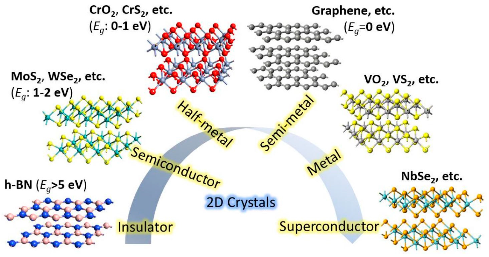
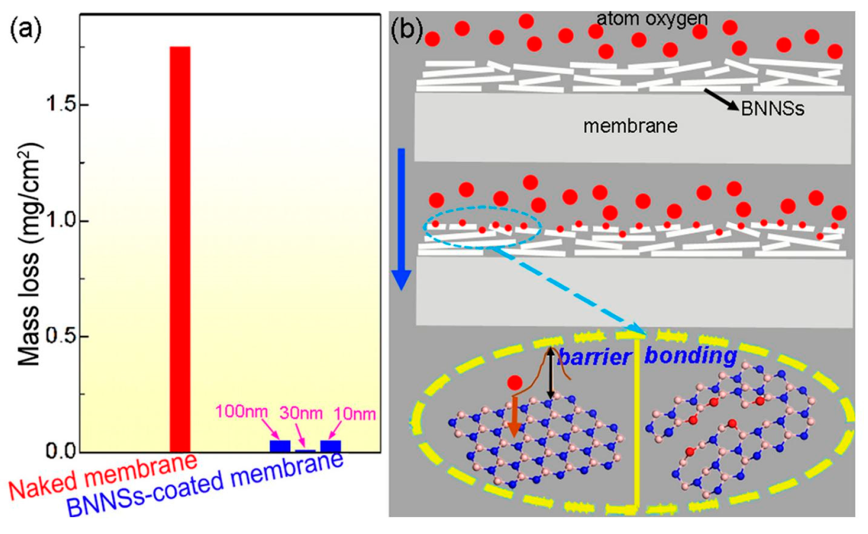
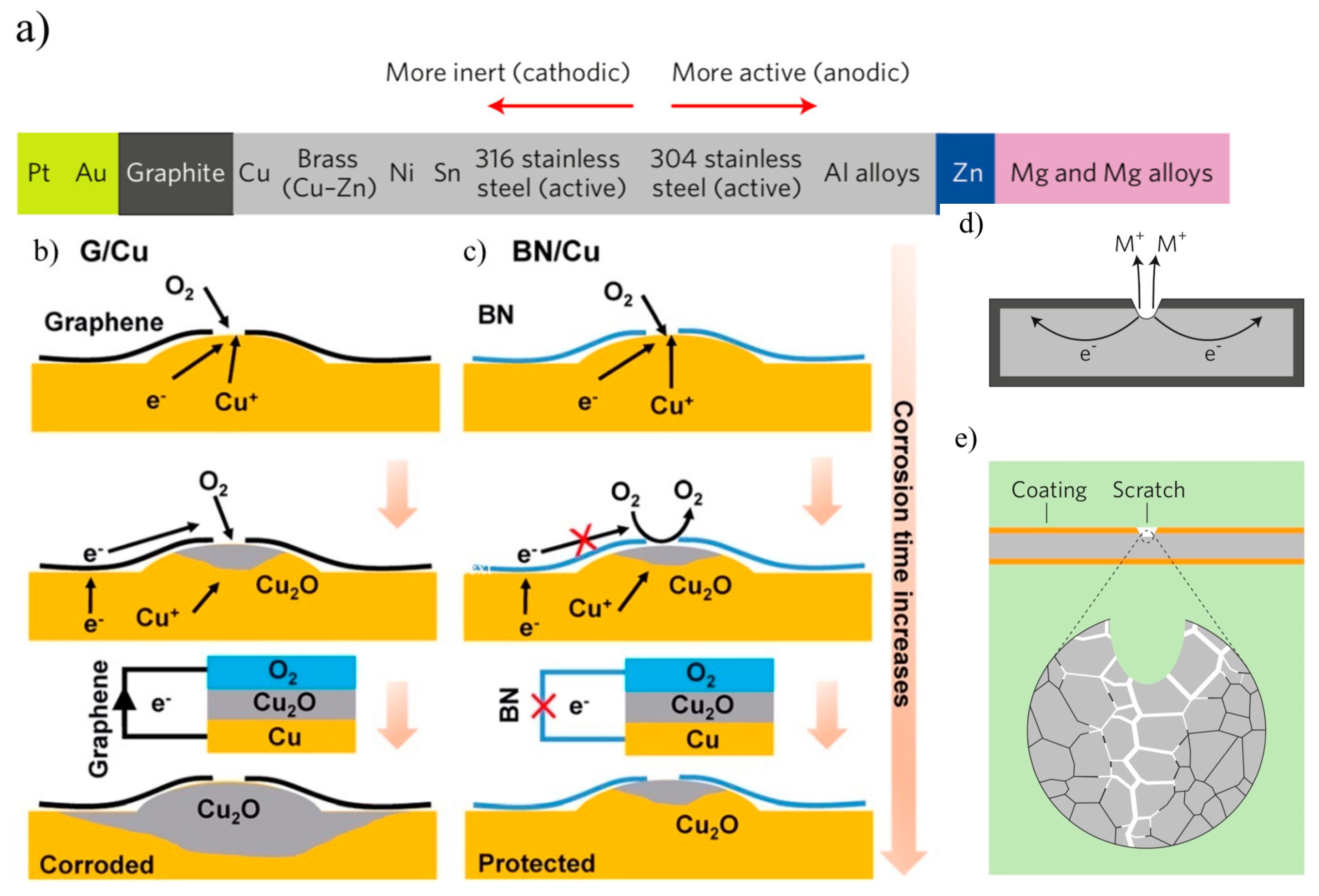
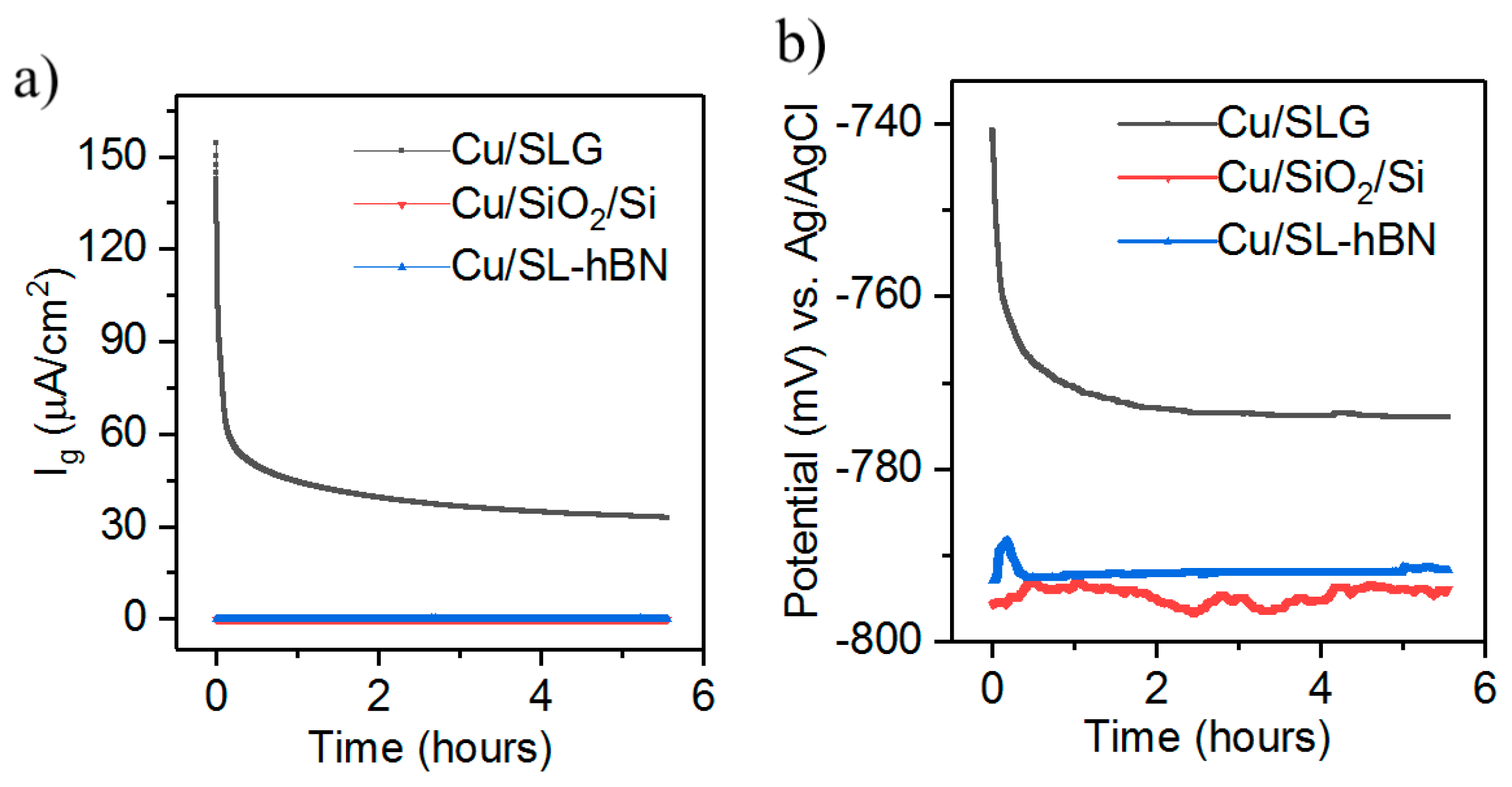
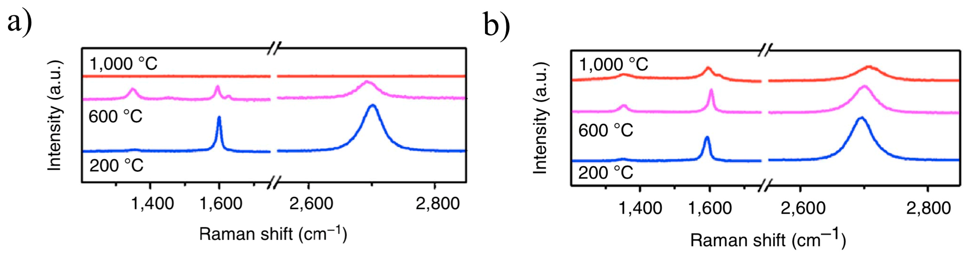
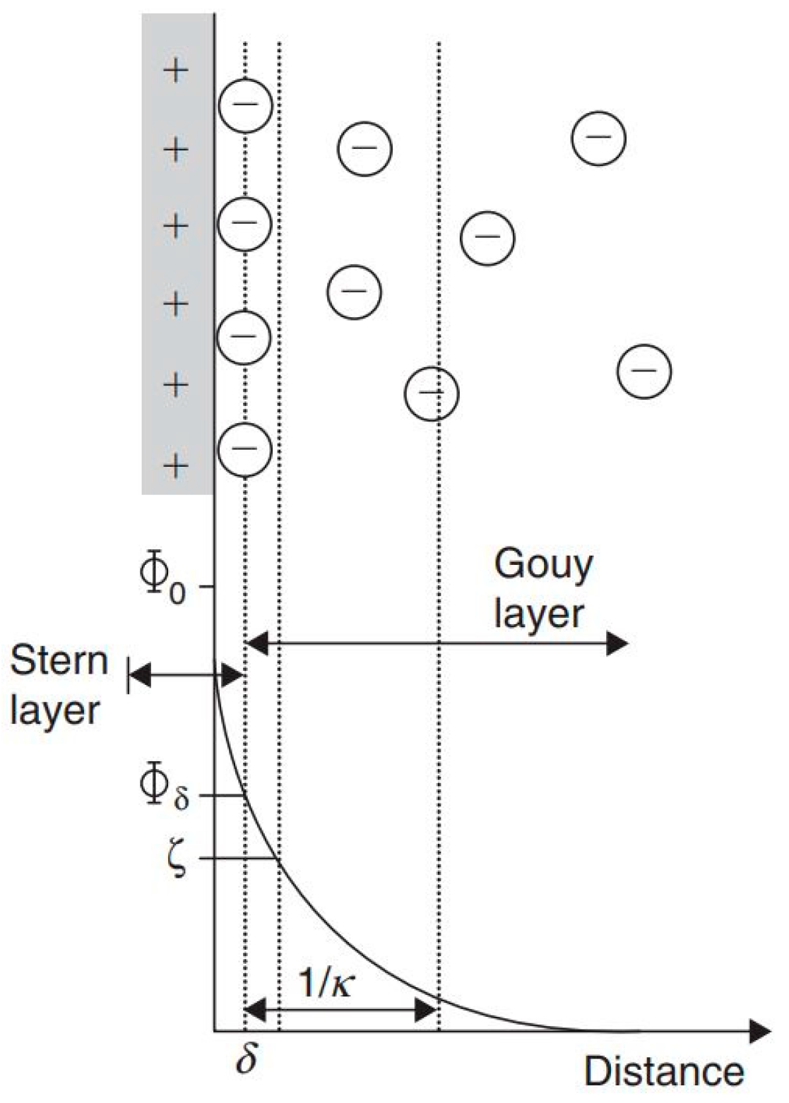
Table 1.
Application of different technique in corrosion characterization of metallic surfaces.
| Characterization Technique | Applications |
|---|---|
| Optical microscopy | Identifying oxide formation after corrosion [71,72,73]. |
| Raman spectroscopy | Identifying the grain boundaries (GB), defects in the 2D coating, and the presence of oxides after corrosion on the metallic surface [74]. |
| X-ray photoelectron spectroscopy (XPS) | Detecting the presence of oxides by quantifying the chemical composition of the substrate after corrosion [75]. |
| X-ray powder diffraction (XRD) | Determining the substrate crystal structure, identify oxide formation after corrosion [76,77]. |
| Scanning electron microscopy (SEM) | Identifying the presence of wrinkles, defects, and morphology of 2D coating [78]. |
| Energy-dispersive X-ray spectroscopy | Determining the elemental composition and quantitative value of each corrosion product (i.e., the oxides) [79,80]. |
| Atomic force microscopy (AFM) | 2D material coating continuity, GB, and the number of layers determination [81]. |
| Scanning tunneling spectroscopy (STS) | Detection of cracks and ruptures on 2D material though differential conductance spectrum (dI/dV) including the Local density of states (LDOS) mapping [82]. |
Table 2.
Galvanic corrosion current density and corrosion rate. Reprinted with permission from ref. [49]. Copyright 2018 American Chemical Society.
Table 2.
Galvanic corrosion current density and corrosion rate. Reprinted with permission from ref. [49]. Copyright 2018 American Chemical Society.
| Galvanic Couple | Galvanic Current Density (Ig) (μA/cm2) | Corrosion Rate (mpy) |
|---|---|---|
| Cu/SiO2/Si | 6.22 × 10⁻³ | 2.8 × 10⁻³ |
| Cu/SLG | 32.9 | 14.8 |
| Cu/SL-hBN | 8.4 × 10⁻² | 3.79 × 10⁻² |
Table 3.
Measurement of Cdl for 2D material coated Cu in 0.1 M NaCl solution. Adapted under Creative Commons Attribution-NonCommercial 3.0 Unported Licence from ref. [70]—Published by The Royal Society of Chemistry.
Table 3.
Measurement of Cdl for 2D material coated Cu in 0.1 M NaCl solution. Adapted under Creative Commons Attribution-NonCommercial 3.0 Unported Licence from ref. [70]—Published by The Royal Society of Chemistry.
| Sample | |
|---|---|
| Bare Cu | 53 |
| Graphene-coated Cu | 17 |
| hBN coated Cu | 3.3 |
Table 4.
Brief summary of different parameters of 2D material/metal system available in literature.
| 2D Material | Substrate | Fabrication Technique | Coating Thickness | Sample Size (cm2) | Surrounding Environment | Reference |
|---|---|---|---|---|---|---|
| Graphene | Ni, Cu | As grown (CVD) and transferred | 1–4 layers | 0.4 | 0.1 M NaSO4 | Prasai et al. [17] |
| Graphene | Ni, Cu | As grown (CVD) | ~1 layer | 0.071 | 0.1 M NaCl | Kirkland et al. [90] |
| Graphene | Cu | As grown (CVD) and transferred | 8–45 Å | 1–2 | 5 wt% NaCl | Zhu et al. [121] |
| Graphene | Low alloy steel | Dip coating | 1–6 layers | 06 | Water (pH 6), 3.5 wt% NaCl, 1.0 M NaOH, 0.1 M HCl | Pavan et al. [57] |
| Graphene | 2024 Al alloy | CVD and subsequently | ~1–2 layers | 01 | 3.5 wt% NaCl | Zheng et al. [181] |
| Graphene | Cu | As grown (CVD) | 4–5 layers | 0.785 | 0.1 M NaCl | Tiwari et al. [92] |
| Graphene | Cu, Al | CVD and subsequently transferred | 1–4 layers | 01 | 0.1 M NaCl | Mišković-Stankovic et al. [182] |
| APTES functionalized graphene | Cold tolled mild steel | Bar coating | 200,000 Å | 0.0636 | 3.5 wt% NaCl | Aneja et al. [160] |
| APTES functionalized GO | Cu | Electrophoretic deposition (EPD) | 15–25 Å | 01 | 3.5 wt% NaCl | Raza et al. [183] |
| Graphene/waterborne inorganics | Steel | Spray coating | 400,000–500,000 Å | 27.3 | 3.5 wt% NaCl | Cheng et al. [184] |
| graphene/Polymeric isocyanate crosslinked with hydroxy functional acrylic Adhesive (PIHA) | Cu | EPD | 400–450 Å | 01 | 0.1 M NaCl | Singh et al. [185] |
| GO/plasma electrolytic oxidation (PEO) | ZK60 magnesium alloy | Dip coating | 40,000–60,000 Å | 01 | 3.5 wt% NaCl | Qiu et al. [32] |
| hBN | Cu | As grown (CVD) | 1 layer | 01 | Sulfate-reducing bacteria Desulfovibrio alaskensis G20 | Chilkoor et al. [49] |
| hBN | Cu | As grown (CVD) | ~4.5 Å | 0.07 | 0.1 M NaOH | Mahvash et al. [186] |
| Graphene and hBN | Cu | CVD and subsequently transferred | 1 layer | 01 | Escherichia coli MG1655 bacterial cultures. | Parra et al. [48] |
| hBN/polyvinyl alcohol (PVA) | Steel | Spin coating | ~93,300 Å | 1.98 | Simulated Seawater | Husain et al. [79] |
| hBN/polydopamine/epoxy | Steel | Spray coating | 800,000 Å | 3.6 | 3.5 wt% NaCl | Zhang et al. [187] |
| hBN/epoxy | Steel | Bar coater | 200,000 Å | 01 | 3.5 wt% NaCl | Cui et al. [188] |
| hBN/Chitosan/titania | Steel | EPD | 120,000–150,000 Å | 0.78 | Dulbecco’s Modified Eagle Medium (cell culture medium) | Raddaha et al. [189] |
Table 5.
A brief overview of various fabrication techniques of 2D coating on a target substrate.
| Fabrication Technique | Brief Overview | Reference |
|---|---|---|
| CVD | CVD is a high-temperature deposition technique carried out with appropriate precursors in either vacuum or atmospheric condition. Extensive reports have been made on corrosion performance evaluation of metallic surfaces passivated by CVD-grown 2D materials. As grown or transferred 2D material can be used for anticorrosive coating of metal. An advantage of using as grown 2D material/metal is to avoid the transfer-induced defects. | Tulegenova et al. [87], Kirkland et al. [90], Tiwari et al. [92], Nilsson et al. [178] |
| Bar coating | Precision film coating formation can be performed using bar applicator, which is a technique analogous to painting. | Aneja et al. [160], Cui et al. [188] |
| Brushing | An ink-based coating can be brushed on target metallic surface using a brush to form anticorrosive thin film coating. | Krishnamoorthy et al. [190] |
| EPD | During EPD, the electrical attraction between two oppositely charged particles suspended in a solution is utilized to deposit an intrinsic or composite 2D coating. | Singh et al. [185], Raddaha et al. [189], Tozar et al. [191] |
| Spin coating | Solution based 2D material can be placed on a target substrate and coated using the centrifugal force generated due to substrate rotation. | Mayavan et al. [192] |
| Spray coating | 2D material (intrinsic or composite form) can be deposited by spraying onto the substrate in either powder or solution form. | Zhang et al. [187], Su et al. [193] |
| Rapid thermal annealing (RTA) | A rapid and facile heating process to pyrolysis organic compounds (e.g., naphthalene for graphene) to form 2D material on target substrates. | Huh et al. [29], Mogera et al. [194] |
| Vacuum filtration | Solution based 2D material can be deposited onto porous polymer target substrates using vacuum pressure to form a protective coating. | Yi et al. [60] |
| Dip coating | Substrates can be immersed in a 2D material dispersed solution to form an anticorrosive film coating with subsequent drying procedure. | Al-Saadi et al. [41], Sun et al. [71], Sun et al. [195] |
| Drop casting | 2D material dispersed solution can be poured onto the target substrate to form anticorrosive film coating with subsequent drying procedure. | Liu et al. [34] |
© 2019 by the authors. Licensee MDPI, Basel, Switzerland. This article is an open access article distributed under the terms and conditions of the Creative Commons Attribution (CC BY) license (http://creativecommons.org/licenses/by/4.0/).
Share and Cite
MDPI and ACS Style
Tanjil, M.R.-E.; Jeong, Y.; Yin, Z.; Panaccione, W.; Wang, M.C. Ångström-Scale, Atomically Thin 2D Materials for Corrosion Mitigation and Passivation. Coatings 2019, 9, 133. https://doi.org/10.3390/coatings9020133
AMA Style
Tanjil MR-E, Jeong Y, Yin Z, Panaccione W, Wang MC. Ångström-Scale, Atomically Thin 2D Materials for Corrosion Mitigation and Passivation. Coatings. 2019; 9(2):133. https://doi.org/10.3390/coatings9020133
Chicago/Turabian StyleTanjil, Md Rubayat-E, Yunjo Jeong, Zhewen Yin, Wyatt Panaccione, and Michael Cai Wang. 2019. "Ångström-Scale, Atomically Thin 2D Materials for Corrosion Mitigation and Passivation" Coatings 9, no. 2: 133. https://doi.org/10.3390/coatings9020133
Note that from the first issue of 2016, this journal uses article numbers instead of page numbers. See further details here.