Abstract
The present study offers mathematical calculations of the roll-coating procedure lubricated with an upper-convected Maxwell fluid. An incompressible isothermal viscoelastic fluid was considered, with both the roll and the porous web having uniform velocities. By using the lubrication approximation theory, the desired equations of motion for the fluid applied to the porous web were modelled and analyzed. The suction rate on the web and the injection rate at the roll surface were proportionately anticipated. Results for the velocity profile and pressure gradient were received analytically. Fluid parameters of industrial significance (i.e., detachment point, pressure, sheet/roll separating force, power contribution, and coating thickness) were also calculated numerically. A substantial and monotonic increase was witnessed in these quantities with the increase of flow parameters.
1. Introduction
In the said procedure, a fine uniform liquid layer was deposited onto a substrate. The fluids used for this purpose generally have non-Newtonian properties. The latter phenomenon earned a healthy reputation during the past few decades owing to its vast application. Thin, uniform liquid coatings are produced on surfaces in many industrial processes. This process includes paper coating, beatification and protection of fabrics or metal with coating materials, photographic films, coated products, and magnetic recording. Such operations depend on a large variety of equipment. Among these, roll coaters are common in use. Applied mathematicians, numerical analysts, and modelers must usually undergo serious difficulties when developing appropriate algorithms for calculating such flows; this is due to complex and higher-order leading flow equations of non-Newtonian fluids, as compared to Navier–Stokes equations. Many leading equations of non-Newtonian fluids have been proposed in the literature for such complicated flows. Some valuable research in this direction is mentioned in [1,2]. The use of pseudo-plastic fluids, these being non-Newtonian, is very common. The study of pseudo-plastic fluids has gained significance because of its maximum uses in the industry. Emulsion-coated sheets, such as photographic films or solutions and melts of high molecular weight polymers and polymer sheets extrusion, are some common examples of such types of flows. Some attention has been given to the model of upper-convected fluid model, which displays behavior consistent with pseudo-plastic fluids.
For a better understanding the process, many theoretic studies have been undertaken by scientists. Taylor and Zettlemoyer [3], employing the lubrication theory, studied the flow behavior of ink in a printing press process. Results of pressure distribution and force were derived by them. The flow of water between two rolls was deliberated upon by Hintermaier and White [4], who employed the lubrication theory and tested the results, which were consistent with their experimental outcomes. Greener and Middleman [5] further attempted to establish the theory of the forward roll coating flow of Newtonian fluids, performing the traditional lubrication approximations along with some simple physical concepts. A model of Greener and Middleman, where two rollers of equal or non-equalize rotate at equal or non-equal speeds and thereby develop a model which was applicable to a general case, was studied and improved by Benkreira et al. [6]. The findings of their model were consistent with experimental data. Lubrication approximation theory was performed by Souzanna Sofou and Evan Mitsoulis [7] for provision of numerical outcomes in roll coating development over a continuous flat web, by using Herschel–Bulkley model of viscoplasticity, which reduces to the Bingham, power-law, and Newtonian models with suitable modifications.
A fresh rolling contact solver was provided by Wang et al. [8] using a semi-analytical technique for analyzing three-dimensional stable rolling connections. They included creep effects and showed that the new solver includes both normal and tangential contact problems for the trancing of pressure and shear; comparing with current analytical and numerical alternatives demonstrates the precision and effectiveness of the method. Zahid et al. [9] discussed the roll-coating procedure of an incompressible viscoelastic fluid, with the roll and the substrate having uniform velocities. A lubrication approximation theory was used to simplify the conservation equations. A regular perturbation technique was then applied to obtain solutions of velocity profile, pressure gradient, flow rate per unit width, and shear stress at the roll surface. Recently, LAT lubrication approximation theory) was used by Zahid et al. [10] to provide numerical results of a material of second grade. Engineering quantities such as coating thickness, split location, pressure distribution, stresses, strengths, roll power input, and adiabatic temperature rise were obtained between the coating roll and the coated web. Sun et al. estimated the coating system between ether molecules and iron (Fe) nanoparticles [11]. Most recently, a three-dimensional transient finite element model was created by Li et al. [12] to study the evolution of the temperature domain during laser cladding of AlSiTiNi coatings on a 304 stainless steel substratum. In this model, the melting and solidification process as well as the geometric morphology of the laser cladding coatings were simulated using a planar Gauss heat source and a temperature selection judgment mechanism.
To the best of our knowledge, no contribution is available for the mathematical formulation of the coating process over a porous web with constitutive equations of upper-convected Maxwell fluid flow. The aim of this article was to develop the flow process of the coating over the porous web of a convected Maxwell fluid as well as to investigate the influence of fluid physical properties during this procedure. The article develops as follows: the following sections focus on conservation equations followed by modelling, the subsequent part covers the analytic expressions of the flow parameters, and finally, findings and discussion along with deductions are presented.
2. Mathematical Formulation
For depositing liquid onto a moving substrate, a laminar, steady flow of an incompressible isothermal upper convected Maxwell fluid is under consideration. The roll with radius R is rotating counter-clockwise with an angular velocity U = Rω. The plane and the roll are moving linearly with the same velocity, with H0 as the separation at the nip. During the procedure, the suction velocity v0 is assumed to remain constant. Moreover, the x-axis is taken along flow motion, whereas y-axis is assumed to be transversal to the flow direction, as depicted by Figure 1. The symmetry of the model is pursued for the analysis. The motion of the upper-convected Maxwell fluid model is discussed using the following equations:
where , , and are velocity, density, the material derivative, and pressure, respectively. represents the extra stress tensor for the upper-convected Maxwell fluid model, which is given by
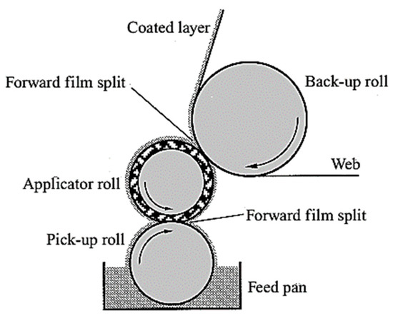
Figure 1.
Sketch of the physical model under study.
The length of the curved channel being established by the roll and the plane is too large when comparing with the separation at the nip, that is, , thus causing the flow two dimensional. The velocity field is assumed as
Because of Equation (4), Equations (1) and (2) in components form become:
where β and v0 represents viscoelastic parameter and suction velocity, respectively.
Based on the lubrication theory we get
where .
After rearranging Equation (9), we get
Equation (10) represents the final equation of motion under porous substrate geometry in dimensional form. For non-dimensional expressions, introduce variables defined by
with the help of Equation (11), Equation (10) becomes:
where .
The corresponding dimensionless boundary conditions are
where . Equations (11) and (12) are the final dimensionless modelled equations under the considered physical model.
To evaluate separation point which is unknown, there needs to be two more boundary conditions. At the axis of symmetry, the separation point becomes stagnation point:
The concluding boundary condition representing a force or pressure balance at the separation point associates the pressure P to the pressure related with surface tension γ
The parameter is a modified capillary number.
The free surface being semicircular, as indicative of Figure 2, leads to a good assumption
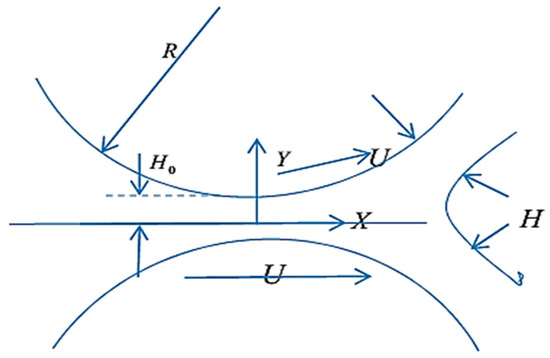
Figure 2.
Mathematical illustration of the region under study.
We know that ; from this we define
and
where λ is a non-dimensional coating thickness, which is the key parameter we pursue to calculate through the model.
3. Solution of the Problem
The result of Equation (12) with boundary conditions (Equation (13)) yields
, being part of the above equation, is still unknown and can be evaluated through introduction of the non-dimensional volumetric flow rate as
Insert Equation (19) into Equation (20), and subsequent integration yields:
Since h(x) is an algebraic function, one may integrate Equation (21) to get the pressure profile p(x)
By using Equation (15), the expression for λ is obtained, which becomes
Separation point is still unknown. For this, substituting Equation (21) into Equation (19), and using boundary conditions (Equation (14)), we get
It is evident from Figure 2 that the film splits uniformly, therefore the separation point is . Velocity and pressure tend to vanish at this position. The assumption can be agreed to, as both the roll and the sheet move with the equal velocity. From this explicit relation, the dimensionless coating thickness λ can be evaluated.
By using Equation (24) into Equation (23), one can use the trapezoidal rule to approximate the complex integral, by fixing , and .
4. Operating Variables
Having calculated the velocity, pressure gradient, and pressure distribution, the remaining desired quantities can now be easily obtained. The operating parameters used for industrial purposes are evaluated as shown below.
4.1. Separating Force
The roll separating force F is given as
where is the dimensional roll separating force per unit width .
4.2. Power Input
The power transferred to the fluid by roll is calculated by integral following, by setting , as
Here, and are the non-dimensional power and stress tensors, given by
4.3. Adiabatic Temperature
The temperature of the fluid is raised due to the power input by an amount which at most, is given by an adiabatic temperature rise
where ρ and is the melting density and heat capacity, respectively, at constant pressure.
5. Results and Discussion
This article analyzes the forward coating process over a porous web for an incompressible isothermal upper-convected Maxwell fluid. The flow equations were simplified by applying lubrication approximation theory. The numerical outcomes of the exiting coating thickness, the separation point xs, the separation force, and the power input are highlighted in Table 1, which is generated through a variation of B. The maximum coating thickness of up to four decimal places is observed which can be as high as 1.5590. Beyond this point by increasing the value of B, the coating thickness up to four decimal places remains the same. The highest separation point is detected at B = 10 which is 2.0630. It is observed that coating thickness increases by increasing B. Physically, it is quite evident that by increasing the viscoelastic parameter, the fluid becomes more viscous. The minimum thickness of coating was observed at B = 1.1, which is 1.1728. It was observed that by setting B → 0, no significant change in coating thickness is found, whereas by setting B → ∞, it is examined that λ → 1.3, as found in the literature by Greener [5] in 1979. It is worth mentioning that with the variation in B, one can really control the coating thickness. Similarly, Table 2 and Table 3 are generated for various values of Re and NCa₂, respectively. It is quite interesting that by increasing the Reynold’s number the coating thickness, both the separation point and separating force decrease as expected. However, with the increase of Reynolds number, the power transferred to fluid by roll also increases. This means that by increasing Reynolds number, the fluid penetration increases, which physically causes a reduction in the engineering quantities. As seen in Table 2, an increase in coating thickness and detachment point is experienced by increasing modified capillary number. Since the capillary number NCa₂ represents the relative effect of the viscous drag force versus the surface tension forces acting across an interface between a liquid and a gas, increasing capillary number viscous forces dominates over interfacial forces; this effect can be seen in Table 3, as by increasing the capillary number separation point, the coating thickness increases as well.

Table 1.
Influence of Maxwell parameter on separation point, coating thickness, separating force, and power input by fixing Re = 10, NCa₂ = 1.
Table 2.
Effect of Reynolds Number on separation point, coating thickness, separating force and power input fixing B = 10, NCa₂ = 1.
Table 3.
Effect of modified capillary number on separation point, coating thickness by fixing Re = 1 and B = 7.
The outcomes for the non-dimensional velocity profiles are shown in Figure 3, Figure 4, Figure 5, Figure 6, Figure 7, Figure 8, Figure 9, Figure 10, Figure 11 and Figure 12. The velocity profile is highlighted at various positions of the roll coating process through variation of B and Re. Figure 3 shows the variation in the velocities curves at the nip region, whereas Figure 4 and Figure 5 are sketched at x = 0.25 and 0.75, respectively, for the increasing values of B. It can be examined that velocity distribution increases by increasing the value of B. This is due to the porous web, otherwise it can have an opposite behavior, because by increasing the value of B, the viscosity of the fluid increases and it becomes more viscous, which can cause reduction in suction of the porous web. Figure 6 and Figure 7 are sketched near the separation point, and here again, the velocity increases by increasing the value of viscoelastic parameter. From Figure 3, Figure 4, Figure 5, Figure 6 and Figure 7, the maximum velocity is observed at the centerline at y = 0, then it starts decreasing and the minimum value of the velocity is 1, as the velocity of the roller. Furthermore, from Figure 3, the maximum velocity on the center line at the nip place is 1.9 and it starts to decrease when one moves towards the separation point; it eventually becomes zero at the separation point. Similarly, in Figure 8, Figure 9, Figure 10, Figure 11 and Figure 12, the effect of Reynolds number has been sketched. Figure 8 is drawn at the nip region, whereas Figure 9, Figure 10, Figure 11 and Figure 12 are respectively drawn at x = 0.25, 0.5, 0.75, and 1. It was portrayed from these graphs that by raising the amount of the Reynold’s number, the velocity reduces: by raising the amount of Re, the porosity of the web rises, which furthers slow down the motion of the fluid the x-direction.
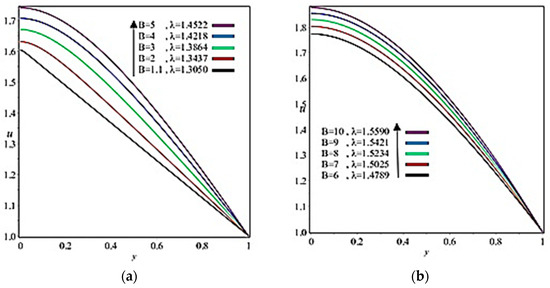
Figure 3.
Influence of B on velocity profile at x = 0. (a) , (b) .
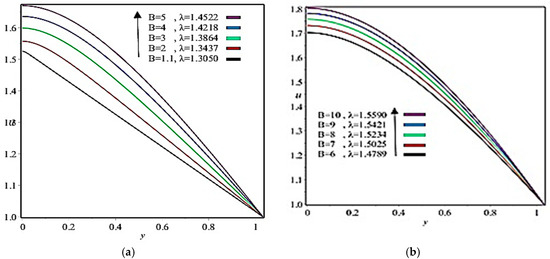
Figure 4.
Influence of B on velocity profile at x = 0.25. (a) , (b) .
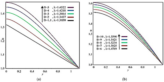
Figure 5.
Influence of B on velocity profile at x = 0.5. (a) , (b) .
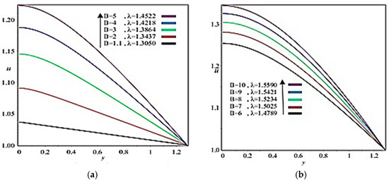
Figure 6.
Influence of B on velocity profile at x = 0.75. (a) , (b) .
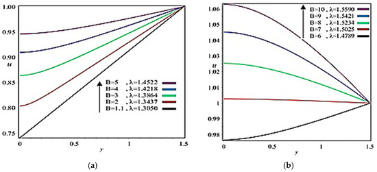
Figure 7.
Influence of B on velocity profile at x = 1. (a) , (b) .
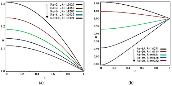
Figure 8.
Influence of Re on velocity profile at x = 0. (a) , (b) .
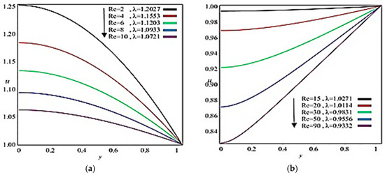
Figure 9.
Influence of Re on velocity profile at x = 0.25. (a) , (b) .
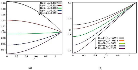
Figure 10.
Influence of Re on velocity profile at x = 0.5. (a) , (b) .
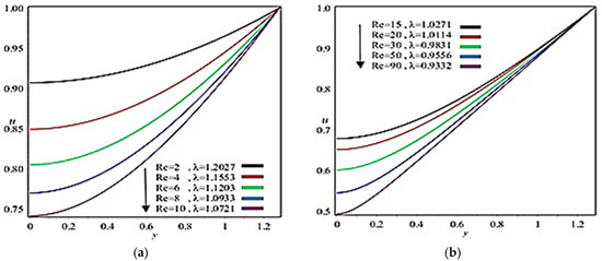
Figure 11.
Influence of Re on velocity profile at x = 0.75. (a) , (b) .
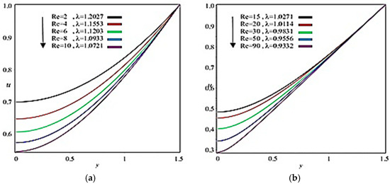
Figure 12.
Influence of Re on velocity profile at x = 1. (a) , (b) .
Figure 13 and Figure 14 show the dimensionless pressure gradient distribution for different values of Reynold’s number and viscoelastic parameter, respectively. Here, by increasing Reynold’s number and the viscoelastic parameter, we are lead to higher values for the maximum pressure, while Figure 15 and Figure 16 show the corresponding dimensionless pressure distribution. One can see that the curves for the pressure get steeper near the minimum gap both for Reynolds numbers as well as for viscoelastic parameter. By increasing the viscoelastic parameter, the material becomes more viscoelastic, the deformations in the flow domain become smaller, and the material behaves more solid-like; it thus requires higher pressures and a larger domain to flow and deform. In the case of porous web pressure, distribution increases as the viscoelastic parameter increases, although an opposite behavior is observed by increasing the Reynolds number.
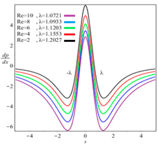
Figure 13.
Axial distribution of the pressure gradient by fixing B = 10.
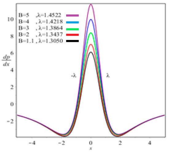
Figure 14.
Axial distribution of the pressure gradient by fixing Re = 10.

Figure 15.
Axial distribution of dimensional pressure fixing Re = 10.
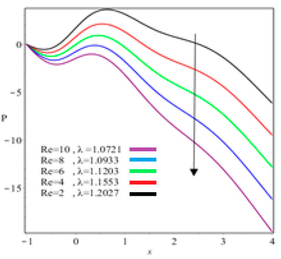
Figure 16.
Axial distribution of dimensional pressure by fixing B = 10.
6. Conclusions
To derive the numerical results of the roll-coating procedure over a moving flat porous web being fed from an infinite reservoir, a mathematical model was developed. A lubrication approximation theory was applied to simplify the equations of motion of the steady upper-convected Maxwell fluid. The main deductions of the current study are as follows:
- In the case of the upper-convected Maxwell fluid model, which is a class of viscoelastic material, a theoretical study was carried out, as most of the material in the coating industry is viscoelastic. Hence the theoretical results for these industries are presented in this study so that they can set their engineering quantities numerically according to the theoretical findings listed in Table 1, Table 2 and Table 3;
- Coating thickness, separation region/separation point, roll separation force, power input, and pressure can be controlled through Reynolds number and fluid parameter ;
- Separating point and coating thickness increases by increasing Capillary number;
- Viscous force has a dominant role on coating thickness, separation force, and power input;
- The outcomes of Middleman [5] are obtained when B → 0 and Re → 0;
- The nip region demonstrates the highest velocity and pressure gradient.
We conclude that film thickness increases as the viscoelastic number increases until a certain higher value; from this point, the tendency remains unchanged. The predictions obtained in this work in general agree with the available theoretical data. The results show that this theoretical prediction is accurate enough for most industrial applications.
Author Contributions
Methodology, M.Z. (Muhammad Zafar); Supervision, M.A.R.; Writing–original draft, B.A. and M.Z. (Muhammad Zafar); Writing–review & editing, M.Z. (Muhammad Zahid) & M.A.R; Results and Discussion, M.Z. (Muhammad Zafar), M.Z. (Muhammad Zahid) and M.A.R.
Funding
This research received no external funding.
Acknowledgments
The authors are thankful to referees for their excellent review.
Conflicts of Interest
The authors declare no conflict of interest.
Nomenclature
| τ | Extra stress tensor |
| ρ | Density |
| B | Viscoelastic parameter |
| μ | Viscosity |
| v | Kinematic viscosity |
| Re | Reynolds number |
| γ | Surface tension |
| λ | Coating thickness |
| NCa₂ | Modified capillary number |
References
- Rajagopal, K.R. A note on unsteady unidirectional flows of a non-Newtonian fluid. Int. J. Non-Linear Mech. 1982, 17, 369–373. [Google Scholar] [CrossRef]
- Benharbit, A.M.; Siddiqui, A.M. Certain solution of the equations of the planar motion of a second grade fluid for steady and unsteady cases. Acta Mech. 1992, 94, 85–96. [Google Scholar] [CrossRef]
- Taylor, J.H.; Zeltlemoyer, A.C. Hypothesis on the mechanism of ink splitting during printing. Tappi J. 1958, 41, 749–757. [Google Scholar]
- Hintermaier, J.C.; White, R.E. The splitting of a water film between rotating rolls. Tappi J. 1965, 48, 617–625. [Google Scholar]
- Greener, J.; Middleman, S. A theory of roll coating viscous and viscoelastic fluids. Polym. Eng. Sci. 1975, 15, 1–10. [Google Scholar] [CrossRef]
- Benkreira, H.; Edwards, M.F.; Wilkinson, W.L. A semi-empirical model of the forward roll coating flow of Newtonian fluids. Chem. Eng. Sci. 1981, 42, 423–437. [Google Scholar] [CrossRef]
- Souzanna, S.; Mitsoulis, E. Roll-over-web coating of pseudoplastic and viscoplastic sheets using the lubrication approximation. J. Plast. Film Sh. 2005, 21, 307–333. [Google Scholar]
- Wang, Z.; Jin, X.; Keer, L.M.; Wang, Q. A numerical approach for analyzing three-dimensional steady-state rolling contact including creep using a fast semianalytical method. Tribol. Trans. 2012, 55, 446–457. [Google Scholar] [CrossRef]
- Zahid, M.; Haroon, T.; Rana, M.A.; Siddiqui, A.M. Roll coating analysis of a third grade fluid. J. Plast. Film Sh. 2017, 33, 72–91. [Google Scholar] [CrossRef]
- Zahid, M.; Rana, M.A.; Siddiqui, A.M. Roll coating analysis of a second-grade material. J. Plast. Film Sh. 2018, 34, 141–164. [Google Scholar] [CrossRef]
- Sun, J.; Hui, S.; Liu, P.; Sun, R.; Wang, M. Investigations on forming ether coated iron nanoparticle materials by first-principle calculations and molecular dynamic simulations. Coatings 2019, 9, 395. [Google Scholar] [CrossRef]
- Liu, C.; Li, S.; Zhang, Z.; Zeng, M.; Wang, F.; Wang, J.; Guo, Y. Numerical simulation of thermal evolution and solidification behavior of laser cladding AlSiTiNi composite coatings. Coatings 2019, 9, 391. [Google Scholar] [CrossRef]
© 2019 by the authors. Licensee MDPI, Basel, Switzerland. This article is an open access article distributed under the terms and conditions of the Creative Commons Attribution (CC BY) license (http://creativecommons.org/licenses/by/4.0/).