
Electromagnetic Interference Shielding with Electrospun Nanofiber Mats—A Review of Production, Physical Properties and Performance


1
Institute of Physics—Center for Science and Education, Silesian University of Technology, 44-100 Gliwice, Poland
2
Thin Films & Physics of Nanostructures, Bielefeld University, 33615 Bielefeld, Germany
3
Faculty of Engineering Sciences and Mathematics, Bielefeld University of Applied Sciences, 33619 Bielefeld, Germany
*
Author to whom correspondence should be addressed.
Fibers 2022, 10(6), 47; https://doi.org/10.3390/fib10060047
Submission received: 28 April 2022
/
Revised: 16 May 2022
/
Accepted: 23 May 2022
/
Published: 24 May 2022
(This article belongs to the Collection Feature Papers in Fibers)
Abstract
:With a steadily increasing number of machines and devices producing electromagnetic radiation, especially, sensitive instruments as well as humans need to be shielded from electromagnetic interference (EMI). Since ideal shielding materials should be lightweight, flexible, drapable, thin and inexpensive, textile fabrics belong to the often-investigated candidates to meet these expectations. Especially, electrospun nanofiber mats are of significant interest since they can not only be produced relatively easily and cost efficiently, but they also enable the embedding of functional nanoparticles in addition to thermal or chemical post-treatments to reach the desired physical properties. This paper gives an overview of recent advances in nanofiber mats for EMI shielding, discussing their production, physical properties and typical characterization techniques.
1. Introduction
Reducing the electromagnetic radiation in a given area, e.g., to protect sensitive instruments and other electronics or also humans from radiation, is performed by electromagnetic interference (EMI) shielding materials. Such materials work by reflection as well as by absorption. Especially shielding of radio frequency radiation is often necessary due to the increasing number of sources emitting in the range of ~104–1012 Hz, such as computers, electric motors, power lines, etc. [1,2,3]. Below this frequency range, low-frequency (typically up to some kilohertz) or quasi-static (typically up to some hertz) as well as static electric and magnetic fields are sometimes also shielded, e.g., in earthbound experiments simulating space missions, where the Earth’s magnetic field is undesired, or in magnetic resonance tomography (MRT) where health personnel should not be exposed to large magnetic fields [4,5,6].
Generally, high-frequency electromagnetic fields are shielded by conductive materials, while low-frequency magnetic fields are shielded by magnetic materials with high permeability (µ > 104), and electrostatic fields are shielded by grounded-conductive shells [7,8].
Shielding effectiveness describes a reduction in the transmission of electromagnetic waves by the shielding material. The transmission coefficient T is defined as
with the electric (magnetic) field intensity without shielding E0 (H0) and with shielding Et (Ht), respectively [9]. The shielding effectiveness SE is defined as
with the power P0 (Pt) for the measurement without (with) shielding [9]. The SE is composed of shielding due to reflection (R), absorption (A), and multiple reflections (M) [10]:
This formula indicates which materials may be suitable for electromagnetic shielding. Reflection losses SER will occur for electrically/magnetically conducting materials and be greater for higher conductivity and lower permeability; absorption losses SEA occur upon interaction between electric or magnetic dipoles in the material with the electromagnetic field and are larger for high conductivity and high magnetic permeability; while multiple reflection losses SEM are usually small and often neglected if the distances between reflecting surfaces or interfaces are much larger than the skin depth [11]. It must be mentioned that mobile charge carriers, i.e., electrons or holes, can result in reflection losses even if no percolation/conduction paths are formed, so that even materials that are not conductive on a macroscopic scale can cause reflection losses for electromagnetic waves [11]. This is especially important in case of integrating conductive nanoparticles in coatings or nanofibers where the filling may be insufficient to form percolation paths, or where the nanoparticles may be coated with an isolating shell to prevent them from oxidation.
Sometimes, a deeper view into the shielding mechanisms is possible, especially in correlation with simulations. Wang et al., e.g., subdivided the polarization properties of graphene-based hetero-structures into defects (vacancy, point defect and large-scale defect), polar groups and interfaces and underlined their importance for the EM properties of a dielectric material, in addition to the conductive properties of the material [12,13]. These results were gained by measurements of the real and imaginary part of the complex dielectric permittivity at different temperature and frequencies as well as by first-principle calculations.
Another important point is the skin effect, meaning that high-frequency electromagnetic fields can only penetrate into the surface region of a material, not into the bulk, where these skin depths decrease with increasing frequency, conductivity and permeability [11]. For metals such as copper or nickel, electromagnetic fields of 1 GHz frequency are reduced to 1/e at penetration depths around 0.5–2 µm, showing that electromagnetic shielding can normally be performed by relatively thin shields. This is why many authors describe electromagnetic shields by textile fabrics, either woven, knitted or other macroscopic fabrics [14,15,16,17,18] or even nanofiber mats, as will be presented in this paper.
This review is organized as follows: In the next sections, different measurement methods are presented, followed by a short description of the electrospinning technique and the different fibers and mats that can be produced in this way. Different physical properties of nanofibers, such as conductive or magnetic properties, can be intrinsic to the nanofibers or added by a post-treatment, which will be described subsequently, followed by other factors influencing the shielding properties of a nanofiber mat, such as thickness or porosity.
2. Measuring Electromagnetic Shielding and Related Parameters
Electromagnetic shielding is mostly measured according to the ASTM D4935-18 standard [19]. It is based on using a vector network analyzer combined with a test fixture in which, alternatingly, reference and test specimens are embedded, as shown in Figure 1 [20].
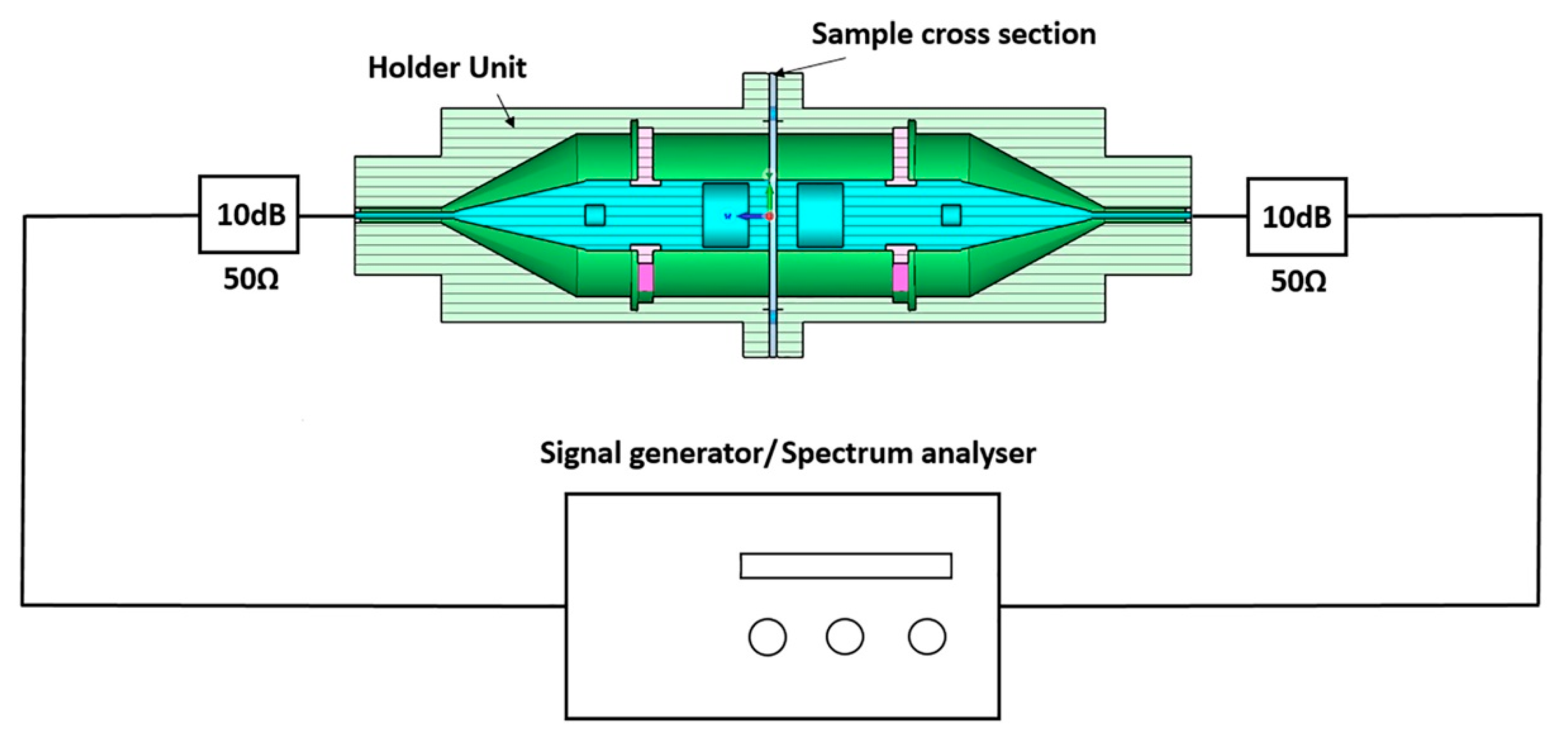
In this so-called waveguide method, these specimens are placed in a coaxial specimen holder unit, as defined in the standard, and investigated by a setup as depicted in Figure 2 [21]. Here, a network analyzer is coupled with the specimen holder where the outer conductor of the coaxial transmission line is extended throughout the whole holder unit (green parts), while the fabrics placed at the position of the sample cross section can shield the signal between the conductive parts. Measurements with the reference specimen are used to define the reference level with the space between the conductors being empty. This setup allows the reflected and the transmitted power, i.e., distinguishing between reflection and absorption losses [21]. Test frequencies are typically in the range of 30 MHz to 1.5 GHz [15,20,21,22], but can also be extended to higher frequencies using appropriate waveguides [23]. Higher frequencies of around 3–30 GHz are typically used in digital telecommunication, satellite communication and waveguide communication, so that especially testing these frequencies is highly in-demand.
Other existing standards are, e.g., related to durable relocatable shielded enclosures (ASTM E1851-15) [24], (IEEE 299-2006) enclosures and boxes [25], or EN 61000-4-21 (identical to IEC 61000-4-21) [26] which necessitates a special chamber, so that textile shielding fabrics are often investigated by the aforementioned ASTM D4935-18. Nevertheless, this standard is not unproblematic, due to the edge-contact requirements which may cause large measurement errors [27]. Marvin et al. thus suggested using a simple system in which the sample is placed between source antenna and receiving antenna, the latter of which is fully embedded in an absorber material to avoid diffracted waves reaching the receiving antenna [27]. They showed that a shielding effectiveness of up to 100 dB could be measured in a broad frequency range between 1 GHz and 8.5 GHz.
Besides these potential edge contact problems, Vasquez et al. mentioned the not fully defined specifications of the tester, such as unclear surface finish and end dimensions, while the ends, in addition, do not fit properly to standard connectors, in addition to the large mass of the tester around 18 kg [28]. They suggested a simplified design which could be attached to N-type standard connectors at the ends to the usual 50 Ω/10 dB attenuators (cf. Figure 2), with significantly smaller samples of diameters 30.48 mm to also enable testing materials that are difficult to produce in larger quantities. For their tester, they calculated a theoretical cutoff frequency of 18.2 GHz and tested it up to 13.5 GHz and found satisfactory results for various materials.
Valente et al. used mathematical characterizations of SE testers similar to the standard one by investigating impedance mismatch and lossless network conditions [29]. They suggested a larger cross-section to avoid strong discontinuities in smaller testers due to the sample thickness and underlined the importance of high dimensional accuracy and improved surface finishing to avoid impedance mismatches.
In contrast to these methods, Perumalraj et al. used an open-space method to investigate the electromagnetic shielding of conductive textile materials [30]. A general overview of possible measurement setups was given by Geetha et al., who differentiate them into open-field (free-space) methods, shielded-box methods, shielded-room methods and the coaxial transmission-line methods, to which the ASTM D4935-18 belongs [31]. Their evaluation of the different methods is given here in brief, showing that different methods may have their advantages and disadvantages for different samples and frequency ranges under investigation:
- -
- Open-field (free-space) method—distance of 30 m between device and receiving antenna; wide variations due to differences in product assembly.
- -
- Shielded-box method—metal box with sample port in one wall, receiving antenna inside, transmitting antenna outside; difficult electrical contact between test specimens and shielded box, limitation of the frequency range to about 500 MHz, poor correlation between tests in different laboratories.
- -
- Coaxial transmission line—e.g., ASTM D4935; standard method for planar specimens, time consuming (several minutes to hours per spectrum, depending on the measurement method), typically in the range from 10 kHz to 1 GHz.
- -
- Shielded-room method—similar to shielded box method, anechoic chamber of typical ground area 2.5 m², large test specimens needed between transmitting and receiving antenna [31].
As mentioned before, the conductive and magnetic properties of the samples play an important role for the shielding effectiveness of a material, although even insulating materials with embedded conductive particles will have a certain shielding effect. While the conductivity of a rigid material can unambiguously be measured, this is much more complicated for textile materials. For low conductivities, a teraohm-meter can be used, as described in DIN 54345-1, working with circular electrodes and exerting a defined pressure on the fabric with defined electrode distances. For higher conductive fabrics, different suggestions can be found in the literature. Knittel and Schollmeyer used contacting bars at a defined distance upon which they exerted a defined load to measure the in-plane resistance of a woven fabric [32]. In addition, solder lines were applied on the textile fabric along the positions of the contact bars to further increase the contact between measurement instrument and conductive coating on the fabric. The problem of high contact resistances was also mentioned by Kacprzyk, who found that, even in circular electrode systems such as a teraohm-meter, and in three-electrode systems used for volume or surface resistance measurements, high contact resistances can significantly influence the measured surface or volume resistance [33]. Even in four-probe measurements, normally used for measurements of small resistances or, more generally, resistances that are small in comparison to the contact resistance between sample and measurement, deviations from the real value occur if the contact resistance is too high, causing problems during bioimpedance measurements with textile electrodes and similar dry electrodes contacting the skin [34].
This is even more problematic regarding conductivity measurements on nanofiber mats on which no large pressure can be exerted without the danger of damage. While several papers reporting on the electric conductivity of electrospun nanofiber mats mention the four-probe method [35,36,37], only few of them explain the contacting process. Some papers describe measurements based on commercial four-point probes, e.g., the Jandel RM3 Test unit [38,39], which try to exert a standardized pressure onto textile and similarly soft samples. Some authors mention the use of a conductive silver paste to create a reliable contact [40,41,42], which is in our experience quite often carried out, but unfortunately not always mentioned in the resulting papers, although it is a good method to enlarge the contact area without squeezing the fibers.
Magnetic properties are usually measured contact free and nondestructively, so that the aforementioned contact problems do not occur here. Optical methods, such as measurements of the magneto-optic Kerr effect (MOKE), are generally highly complicated on rough surfaces [43] and thus usually not taken into account. Instead, instruments such as an alternating gradient magnetometer (AGM), vibrating sample magnetometer (VSM), or superconducting quantum interference device (SQUID) are used, which enable measuring even very small magnetic moments [44,45,46,47].
3. Electrospinning Techniques
Electrospinning is described in detail in many review papers and books, including the most recent developments [48,49,50]; thus, here, only a short overview of the principle is given and of different fiber and nonwoven structures that can be gained by it.
Generally, electrospinning works by introducing polymer droplets into a strong electric field, mostly by a syringe (needle-based electrospinning, Figure 3a [51]) or by constantly coating a wire with the solution (wire-based electrospinning, Figure 3b [52]). Many other possibilities exist to introduce the polymer solution or melt into the electric field, e.g., by rotating spinnerets, often aiming at an improved spinning efficiency [53]. A special form of needle-based electrospinning is coaxial electrospinning, applying a needle with an inner and an outer nozzle through which two different polymer solutions or other fluids can be pressed to create, e.g., core-shell fibers [54,55,56].
Inside the electric field, Taylor cones (Figure 3a) are formed at the tip of the needle, along the wire or at any other kind of spinneret, from which a jet of the polymer solution spirals towards the counter electrode, while the solvent evaporates until nanofibers are placed on the collector. The collector especially defines the orientation of the nanofibers to each other—while homogenous, static collectors (Figure 3b) create arbitrarily oriented nanofibers, rotating collectors (Figure 3a) and partly conductive or otherwise-modified substrates can be used to reach a certain alignment of the fibers [57].
4. Functionalization of Electrospun Nanofiber Mats for Electromagnetic Shielding
As mentioned before, the conductive, magnetic and also dielectric properties of nanofiber mats will influence the shielding effectiveness. Improving these properties is possible by adding corresponding blend materials or nanoparticles directly to the spinning solution, in this way creating intrinsic properties of the nanofibers, or by a post-treatment, e.g., by dip-coating, carbonization, etc. This section describes some exemplary possibilities of functionalization. Other factors are the thickness of the nanofiber mat, the fiber diameters and the porosity as well as the fiber orientation, which will also be discussed here in brief.
4.1. Conductive Nanofiber Mats
Conductive nanofiber mats can be prepared by electrospinning from conductive solutions or melts, by carbonization after electrospinning, or by applying a conductive coating [58]. Lee et al. prepared core-shell nanofiber mats with polyvinylidene fluoride (PVDF) as the core and poly (3,4-ethylenedioxythiophene) (PEDOT) as the shell, without additional conductive fillers, and found an increased absorption of electromagnetic waves and multi-reflections due to the porous nanostructure [59]. They reported an SE of approx. 40 dB in the X-band, i.e., in the range of 8–12 GHz.
Combining a conductive precursor and carbonization, Guo et al. used a PAN/TaCl5 solution for electrospinning [60]. After thermal stabilization and carbonization at 1200 °C, they received TaC/C composite nanofiber mats with conductivities around 5–10 × 102 S/m and a shielding effectiveness of 24–38 dB, depending on the nanofiber mat thickness and the production parameters.
A more complicated process of gaining conductive nanofibers was described by Zhang et al., who started with an electrospun poly(acrylonitrile) (PAN) nanofiber mat, which was treated with NaOH and dispersed [61]. This dispersion was mixed with graphene oxide (GO), resulting in a GO-PAN film by filtration, which was afterwards thermally stabilized and carbonized at 2000 °C to create a graphene/carbon fiber film. They found conductivities around 6 × 10⁴ S/m–1.7 × 105 S/m and a shielding effectiveness around 48–56 dB in the X-band for samples prepared with varying production parameters.
Ji et al. also started with a PAN nanofiber mat which was aminated and immersed in a silver–ammonia solution to obtain Ag seeds, before Ag, Cu or Ni coatings were added by electroless deposition of the respective metallic nanoparticles [62]. They found conductivities in the range of 1.3–57 × 105 S/m, depending on the coating material, and a shielding effectiveness of around 50–60 dB for Co and Ni, as well as around 75–90 dB for Ag coating in the range of 8–26 GHz (X-band, Ku-band and K-band), which they also attributed to the high absorption upon multi-reflection, as depicted in Figure 4 [62].
In a similar approach, Kim et al. used electron beam evaporation to coat electrospun nylon (PA66) nanofiber mats with 50 nm of silver [63]. These metallized nanofiber mats, containing oriented nanofibers, were stacked with varying nanofiber orientations and hot-pressed to prepare composites. Conductivities of 2 × 10⁶ S/m and 6 × 10⁶ S/m were reached perpendicular and parallel to the nanofiber orientation, respectively, resulting in a shielding effectiveness of up to 60 dB in the range of 8.2–18 GHz.
A dip-coating method was applied by Lai et al. to prepare a conductive nanofiber network [64]. Starting from glycerol-grafted PAN nanofiber mats, these membranes were immersed into PEDOT:PSS and dried in the air in a stretched state. The authors described that, in this way, the capillary effect during the evaporation of water upon drying resulted in collapsing of the larger pores and thus increased connections between adjacent nanofibers, in this way, increasing the conductivity. They reported conductivities around 102–103 S/m, depending on the preparation parameters, which were fully maintained during 1000 bending cycles. The shielding effectiveness in the range of 8–12.5 GHz was around 22–55 dB, again explained by multi-reflection inside the nanofiber mat.
4.2. Magnetic Nanofiber Mats
In many cases, magnetic nanoparticles are embedded in the spinning solution to prepare magnetic nanofiber mats. Darwish et al. prepared core/shell nanofibers from PA6 and Fe3O4 (magnetite) and found good electromagnetic shielding even for a low magnetite loading of only 1.7 wt% [67]. Im and Park used a higher magnetite content of 11 wt% in PVDF nanofibers and reported that more than 17 wt% magnetite resulted in aggregation of the nanoparticles on the nanofiber surfaces [68]. PAN nanofiber mats with even higher magnetite contents were produced by Mamun et al., e.g., 72 wt% magnetite in the final nanofiber mat with strong agglomerations [69], while smaller amounts or the limitation of the magnetite nanoparticles to the shell of coaxially electrospun nanofibers resulted in even nanofibers without many agglomerations [69,70,71].
Besides magnetite, many other magnetic nanoparticles have been embedded in polymeric nanofibers. Mohammadkhani et al. report on Ni nanoparticles in recycled poly(ethylene terephthalate) (PET) nanofiber mats for EMI shielding [72]. Guo et al. prepared TaC/Fe3C/C electrospun nanofiber mats by pyrolysis and found a high conductivity of approx. 1.5 kS/m, high magnetization at saturation of 13.3 emu/g and a shielding of up to 46 dB in the range of 8.2–12.4 GHz [73]. NiZn ferrite (Ni0.5Zn0.5Fe2O4) nanofibers were prepared by Na et al., resulting in a large magnetization of up to ~60 emu/g [74], while Fokin et al. discussed the influence of thermal stabilization and carbonization on the magnetic properties of magnetite- and nickel-ferrite (Fe2O3/NiO)-containing PAN nanofiber mats [75].
Magnetic coatings are another way to make a nanofiber mat magnetic. Huo et al. used magnetron sputtering with Ni on SiC/C nanofiber mats and found strongly frequency-dependent reflection losses with peaks at 7 GHz, 11.8 GHz and 14.5 GHz which they attributed to interface polarization, as depicted in Figure 5 [76]. They explained the importance of the conductive path in the network to allow transporting excited hopping electrons, in addition to the microwave dissipation due to the magnetic loss of the Ni particles. In addition, multiple interfaces between Ni, SiC and carbon were found to cause dielectric dipole interactions and related relaxations, so that more microwaves were attenuated.
Huang et al. also applied magnetron sputtering of FeCo coatings on carbon nanofibers to reach a magnetization at saturation of ~3 emu/g and a reflection loss of 17–24 dB at 5–15 GHz [77].
Zhang et al. used electroless plating of Ni-Co instead to prepare magnetically coated PAN-poly(urethane) (PU) nanofiber mats [78]. They found a magnetization at saturation of approx. 50 emu/g and an electric conductivity of 7 × 10³–11 × 105 S/m, resulting in a shielding effectiveness of ~30–90 dB for samples with different coatings and nanofiber-mat thicknesses in the frequency range of 8–26 GHz (X-band, Ku-band and K-band).
A simple dip-coating procedure was used by Miao et al. to receive magnetic nanofiber mats [79]. Starting with an electrospun thermoplastic polyurethane (TPU)/PAN/magnetite nanofiber mat, MXene was subsequently added by dip-coating, resulting in a strong adhesion of the MXene nano-sheets to PAN and magnetite. In this way, a magnetization at saturation around 20 emu/g was reached, combined with a conductivity of 6–20 S/m, resulting in a shielding effectiveness of 10–25 dB in the range of 8–12 GHz.
Finally, it must be mentioned that even pure metallic nanofibers can be produced by electrospinning, followed by calcination of the polymer that is necessary as a spinning agent. Yang et al. described electrospinning PAN with Ni(CH3COO)2·4H2O from an N,N-dimethylformamide (DMF) solution, followed by calcination at 550 °C in air and finally reduction under H2 flow at 400 °C to prepare porous Ni nanofibers [80]. They found high magnetization at saturation of 50–55 emu/g, depending on the porosity, and reflection losses of around 40 dB at 10 GHz.
Similarly, Na et al. prepared Ni0.5Zn0.5Fe2O4 nanofibers by electrospinning polyvinyl pyrrolidone (PVP) with Fe(NO3)2·9H2O from DMF, followed by calcination at 650 °C [81]. Depending on the frequency between 0 and 18 GHz, they found maximum losses of 42–60 dB for different absorber thicknesses.
4.3. Morphology of Nanofiber Mats
Besides the conductive and magnetic properties of electrospun nanofiber mats, their morphology also plays an important role for the shielding effectiveness, especially due to the multi-reflection inside the nanofibrous membranes (cf. Figure 4). Nevertheless, these properties are in most studies not varied, so that only few literature reports can be found quantifying these effects.
Yuan et al., reported on designing the morphology of electrospun MnO-nanograin-decorated vanadium nitride/carbon nanofibers, in which the nitriding time could be used to tailor the MnO nanograin shape covering the VN/C nanofibers [82]. They found a high reflection loss of 63 dB at 8.8 GHz and showed that, by adjusting the thickness, the nanofiber mats showed high absorption in the whole X-band and Ku-band.
Li et al., investigated graphene-filled PVA nanofiber mats and found a variation in the nanofiber diameter distribution with the graphene content [83]. However, the graphene content also significantly influenced the surface resistivity, so that a certain variation in the shielding effectiveness with graphene content can not only be attributed to the nanofiber diameter.
Ramlow et al., compared SiCN and SiCN/PAN nanofibers, having average diameters of approx. 1790 and 570 nm, respectively; only the latter showed sufficient return loss due to large-enough open pores between the nanofibers where multi-reflections were possible [84]. They underlined this idea by a comparison with the literature regarding electrospun ceramic nanofibers from Si-based precursors, as depicted in Figure 6, which indicates a relation between small fiber diameters and large return losses [84]. This correlation between morphology and EMI-shielding effectiveness could be expected based on the previously discussed shielding effect of increased multi-reflections inside a nanofiber mat.
After discussion of the different factors influencing the electromagnetic shielding effectiveness, the next sections will give an overview of the most recent research results in this area.
5. Electromagnetic Shielding by Nanofiber Mats in the X-Band and Ku-Band
As could already be expected from the previous sections, most studies working on electromagnetic shielding concentrate on the X-band. Here, some papers from the last years are discussed.
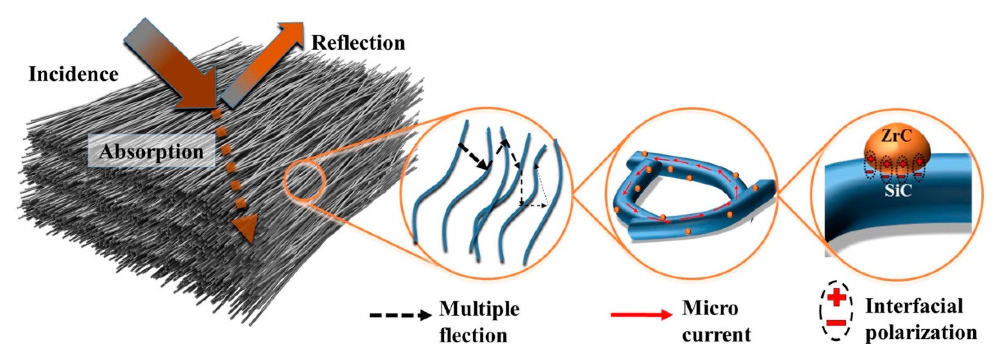
A special composite, suggested by Hou et al., is ZrC/SiC which was prepared by electrospinning a polycarbosilane (PCS) solution with zirconium acetylacetone (Zr(acac)3), followed by pyrolysis of the corresponding nanofiber mat [85]. In this way, the average nanofiber diameter was significantly reduced from 2.6 µm of SiC nanofibers to 330 nm, and the conductivity was increased by five orders of magnitude to 13 S/m, resulting in a shielding effectiveness of 19 dB in the X-band. Interestingly, in high-temperature measurements up to 600 °C, this value was even slightly increased to 20 dB, making this material suitable for high-temperature shielding applications. The shielding process is attributed to a combination of high incidence surface area, highly conductive ZrC nanoparticles resulting in micro-currents on the nanofiber network which lead to conductivity loss, and, finally, grain boundaries and material interfaces between ZrC and SiC which lead to interface polarization and dielectric loss (Figure 7) [85].
Combining conductive and magnetic properties, Nasouri and Shoushtari prepared PVP nanofiber mats with different numbers of embedded magnetite nanoparticles up to 5 wt%, with the last value resulting in undesired agglomerations [86]. They found an increase in the average nanofiber diameter with increasing numbers of nanoparticles and magnetizations at saturation of 4–10 emu/g, in comparison with the value for pure magnetite nanoparticles of approx. 70 emu/g. In addition, the electric conductivity was decreased by four orders of magnitude from the pure PVP go PVP with 4 wt% magnetite. Correspondingly, the shielding effectiveness in the X-band increased from approx. 5 dB of the pure PVP nanofiber mat to 20–24 dB of PVP with 4 wt% magnetite.
A shielding effectiveness between 30 dB and nearly 100 dB was reached by electrospun carbon nanofiber films, combined with silicone in alternating layers of a hot-pressed multilayer stack [87]. Li et al. tested different numbers of layers and showed that this alternating structure was superior to pure carbon nanofiber films, although a pure silicone film did not show any shielding effect.
With a composite of PAN/SiO2 nanofiber mats, coated by Ag nanoparticles in different amounts and dip-coated by 1H,1H,2H,2H-perfluorodecanethiol (PFDT), Li et al. reached conductivities around 2–18 kS/m and a shielding effectiveness of up to 80 dB, depending on AG and PFDT content [88]. Most of the shielding effectiveness was based on absorption, with only a small addition due to reflection.
Many other groups reported new approaches to reaching high electromagnetic-shielding effectiveness by nanofiber mats, e.g., by adding silver nanowires [89], using conductive polymers such as poly(aniline) (PAni) as a coating for cellulose nanofibers [90], coating poly(lactic acid) (PLA) nanofiber mats with MXene [91], multilayer structures with magnetic and conductive properties [92], or combining PVP with Ag nanoparticles to reach a shielding effectiveness of nearly 100 dB [93]. Too many papers are published per year, dealing with electromagnetic shielding in the X-band, to mention more than a small excerpt of them. This is, however, different for other frequency ranges; they will be discussed in the next sections.
Electromagnetic shielding in the Ku band, i.e., in the frequency range of 12–18 GHz, is usually performed together with the X-band, sometimes also combined with the K-band (18–27 GHz) [62]. Yang et al., e.g., prepared a superhydrophobic EMI-shielding material by chemical deposition of silver nanoclusters on an electrospun polymer nanofiber mat and modified it by stearic acid to reach the superhydrophobic effect, enabling using it outdoors [94]. They found a very high shielding effectiveness of 90 dB which they attributed to the high electrical conductivity of 5.7 × 10⁶ S/m, the porous structure and interfacial polarization.
Aiming at shielding in the X-band and the Ku-band, Kim et al. prepared a composite from electrospun PAN and a multiwall carbon nanotube buckypaper by electrospinning and roller coating [95]. They found a shielding effectiveness of approximately 9–23 dB for a very thin system of 0.1 mm thickness.
For the same frequency range, Huang et al. prepared membranes of core-shell nanofibers with Co@C nanoparticles in the shell and graphitic N-doped carbon nanofibers, derived from PAN/PVP electrospun nanofibers, in the core [96]. They reached a high shielding effectiveness of 56 dB and high values along the whole X- and Ku-bands for sample thickness of 4.0 mm and 3.0 mm which they attributed to a superposition of dipolar polarization, interfacial polarization, magnetic coupling and multiple reflections inside the nanofiber mats.
Concentrating on the Ku-band, Xia et al. developed buckypaper/PAN nanofiber composite films by electrospinning PAN, preparing single-walled CNTs which were self-assembled to a buckypaper by infiltration through a nylon filter membrane on a Büchner funnel, and finally forming the composite films by infiltrating the single-walled CNTs into the PAN nanofiber mat [97]. They found conductivities in the range of 9–53 kS/m for the composites, as compared to the pure buckypaper with 57 kS/m, and a total shielding effectiveness of max. 65 dB, which was significantly larger than that of the pure buckypaper due to interfacial polarization along the CNTs and multi-reflections.
As visible from these few examples, quite similar approaches are followed for EMI shielding in the Ku-band, as compared to the X-band.
6. Electromagnetic Shielding by Nanofiber Mats in Other Frequency Bands
Most of the investigations of EMI shielding in the K-band were combined with measurements in the Ku- and often also the X-band [62,78,91,94,98,99], while only few studies can be found concentrating on the K-band only [100,101,102]. Thus, no new approaches can be found in the literature which have not yet been reported for X- and Ku-band.
Few studies were published regarding EMI shielding by electrospun nanofiber mats in the Ka-band (27–40 GHz) [103] and in the C-band (4–8 GHz), typically applying carbon/metal nanofibers [104,105]. Generally, it is necessary to reach a good impedance matching in the desired frequency range to avoid direct reflection of the incident EM waves causing secondary pollution, which can often be tailored by modifying the conductivity and also the thickness of a composite [106].
The pore sizes of electrospun nanofiber mats, however, can only be tailored to a certain extent, in this way limiting the wavelengths of the electromagnetic radiation that can undergo multiple reflections inside the nanofiber mats. This is why lower frequencies, i.e., higher wavelengths, are less often shielded with electrospun nanofiber mats and then typically due to reflection losses [107,108,109]. In addition, lower frequencies are of less technological interest since the microwave range is largely used in communication technologies, with 5G mobile networks extending the earlier mobile communication bands to higher frequencies above 6 GHz for high-speed data transfer, and lower frequencies corresponding to lower energies resulting in reduced danger of health effects on humans [110].
7. Conclusions and Outlook
With increasing use of electromagnetic radiation for mobile communication, extensive research is being performed on EMI shielding. Electrospun nanofiber mats with conductive and/or magnetic properties were shown to be often suitable especially for shielding of radiation in the X-band, partly also in the Ku-band and other bands. A broad range of approaches exists to tailor the shielding effectiveness of nanofiber mats, such as embedding conductive and/or magnetic nanoparticles, carbonization, coating with different methods and materials, or preparing composites with other materials.
This review gives a brief overview of these possibilities, highlighting some of the most recent approaches, to stimulate further research combining and extending the most promising ideas of the state of research and technology.
The increasing number of devices producing electromagnetic radiation especially in increasing frequency ranges, mostly related to communication, will make this research more and more important to protect humans and equipment from unnecessary electromagnetic irradiation, while at the same time not disturbing mobile phones or other communication devices. It can be assumed that textile shielding materials, based on absorption instead of reflection, will become more and more important due to their flexibility and drapability. Especially for these fabrics, it is necessary to develop reliable alternatives to the recently most often used ASTM D4935 to enable the faster screening of soft, flexible, potentially even elastic materials in order to accelerate EMI shielding tests.
Author Contributions
Conceptualization, T.B., A.H. and A.E.; investigation, T.B., A.H. and A.E.; writing—original draft preparation, T.B. and A.E.; writing—review and editing, all authors. All authors have read and agreed to the published version of the manuscript.
Funding
This research was partly funded by the German Federal Ministry for Economic Affairs and Energy (grant no. KK5129710KT1).
Institutional Review Board Statement
Not applicable.
Informed Consent Statement
Not applicable.
Data Availability Statement
Not applicable.
Conflicts of Interest
The authors declare no conflict of interest. The funders had no role in the design of the study; in the collection, analyses, or interpretation of data; in the writing of the manuscript, or in the decision to publish the results.
References
- Wu, J.H.; Chung, D.D.L. Increasing the electromagnetic interference shielding effectiveness of carbon fiber polymer–matrix composite by using activated carbon fibers. Carbon 2002, 40, 445–467. [Google Scholar] [CrossRef]
- Roh, J.-S.; Chi, Y.-S.; Kang, T.J. Electromagnetic shielding effectiveness of multifunctional metal composite fabrics. Text. Res. J. 2008, 78, 825–835. [Google Scholar] [CrossRef]
- Barudov, E.; Ivanova, M. Study of the parameters of conductive textile fabrics for protection against high-frequency electromagnetic radiation. In Proceedings of the 2021 13th Electrical Engineering Faculty Conference (BulEF), Varna, Bulgaria, 8–11 September 2021; pp. 1–5. [Google Scholar]
- EP-European Parliament. Directive 2013/35/EU of the European Parliament and the Council of 26 June 2013 on the minimum health and safety requirements regarding the exposure of workers to the risks arising from physical agents (electromagnetic fields) (20th individual Directive within the meaning of Article 16(1) of Directive 89/391/EEC) and repealing Directive 2004/40/EC. Official Journal of the European Union, 29 June 2013. [Google Scholar]
- Ren, S.; Guo, S.; Liu, X.; Liu, Q. Shielding effectiveness of double-layer magnetic shield of current comparator under radial disturbing magnetic field. IEEE Trans. Magn. 2016, 52, 9401907. [Google Scholar] [CrossRef]
- Blachowicz, T.; Ehrmann, A.; Malczyk, M.; Stasiak, A.; Osadnik, R.; Paluch, R.; Koruszowic, M.; Pawlyta, J.; Lis, K.; Lehrich, K. Plant growth in microgravity and defined magnetic field. In Proceedings of the International Conference on Electrical, Computer, Communications and Mechatronics Engineering (ICECCME), Mauritius, Mauritius, 7–8 October 2021; pp. 1–8. [Google Scholar]
- Yao, Y.Y.; Jin, S.H.; Zou, H.M.; Li, L.J.; Ma, X.L.; Lv, G.; Gao, F.; Lv, X.J.; Shu, Q.H. Polymer-based lightweight materials for electromagnetic interference shielding: A review. J. Mater. Sci. 2021, 56, 6549–6580. [Google Scholar] [CrossRef]
- Weber, M.O.; Akter, F.; Ehrmann, A. Shielding of static magnetic fields by textiles. Ind. Text. 2013, 64, 184–187. [Google Scholar]
- Liang, R.R.; Cheng, W.J.; Xiao, H.; Shi, M.W.; Tang, Z.H.; Wang, N. A calculating method for the electromagnetic shielding effectiveness of metal fiber blended fabric. Text. Res. J. 2018, 88, 973–986. [Google Scholar] [CrossRef]
- Duan, Y.P.; Liu, S.H.; Guan, H.T. Investigation of electrical conductivity and electromagnetic shielding effectiveness of polyaniline composite. Sci. Technol. Adv. Mater. 2005, 6, 513–518. [Google Scholar]
- Chung, D.D.L. Electromagnetic interference shielding effectiveness of carbon materials. Carbon 2001, 39, 279–285. [Google Scholar] [CrossRef]
- Wang, X.-X.; Zhang, M.; Shu, J.-C.; Wen, B.; Cao, W.-Q.; Cao, M.-S. Thermally-tailoring dielectric “genes” in graphene-based heterostructure to manipulate electromagnetic response. Carbon 2021, 184, 136–145. [Google Scholar] [CrossRef]
- Cao, M.S.; Wang, X.X.; Cao, W.Q.; Fang, X.Y.; Wen, B.; Yuan, J. Thermally driven transport and relaxation switching self-powered electromagnetic energy conversion. Small 2018, 14, 1800987. [Google Scholar] [CrossRef] [Green Version]
- Neruda, M.; Vojtech, L. Electromagnetic Shielding Effectiveness of Woven Fabrics with High Electrical Conductivity: Complete Derivation and Verification of Analytical Model. Materials 2018, 11, 1657. [Google Scholar] [CrossRef] [PubMed] [Green Version]
- Ren, W.; Zhu, H.X.; Yang, Y.Q.; Chen, Y.H.; Duan, H.J.; Zhao, G.Z.; Liu, Y.Q. Flexible and robust silver coated non-woven fabric reinforced waterborne polyurethane films for ultra-efficient electromagnetic shielding. Compos. Part B Eng. 2020, 184, 107745. [Google Scholar] [CrossRef]
- Palanisamy, S.; Tunakova, V.; Militky, J.; Wiener, J. Effect of moisture content on the electromagnetic shielding ability of non-conductive textile structures. Sci. Rep. 2021, 11, 11032. [Google Scholar] [CrossRef]
- Pusic, T.; Saravanja, B.; Malaric, K. Electromagnetic Shielding Properties of Knitted Fabric Made from Polyamide Threads Coated with Silver. Materials 2021, 14, 1281. [Google Scholar] [CrossRef] [PubMed]
- Zhang, Y.; Gao, Q.; Zhang, S.; Fan, X.; Qin, J.B.; Shi, X.T.; Zhang, G.C. rGO/MXene sandwich-structured film at spunlace non-woven fabric substrate: Application to EMI shielding and electrical heating. J. Colloid Interface Sci. 2022, 614, 194–204. [Google Scholar] [CrossRef] [PubMed]
- ASTM Committee on Standards. ASTM D4935-18; Standard Test Method for Measuring the Electromagnetic Shielding Effectiveness of Planar Materials. ASTM International: Conshohocken, PA, USA, 2018; p. 11. [Google Scholar]
- Wanasinghe, D.; Aslani, F.; Ma, G.W. An experimental and simulation-based study on the effect of carbonyl iron, heavyweight aggregate powders, and carbon fibres on the electromagnetic shielding properties of cement-based composites. Constr. Build. Mater. 2021, 313, 125538. [Google Scholar] [CrossRef]
- Munalli, D.; Dimitrakis, G.; Chronopoulos, D.; Greedy, S.; Long, A. Electromagnetic shielding effectiveness of carbon fibre reinforced composites. Compos. Part B Eng. 2019, 173, 106906. [Google Scholar] [CrossRef]
- Jung, M.J.; Lee, Y.-s.; Hong, S.-G.; Moon, J.Y. Carbon nanotubes (CNTs) in ultra-high performance concrete (UHPC): Dispersion, mechanical properties, and electromagnetic interference (EMI) shielding effectiveness (SE). Cem. Concr. Res. 2020, 131, 106017. [Google Scholar] [CrossRef]
- Fan, C.; Wu, B.; Song, R.G.; Zhao, Y.T.; Zhang, Y.H.; He, D.P. Electromagnetic shielding and multi-beam radiation with high conductivity multilayer graphene film. Carbon 2019, 155, 506–513. [Google Scholar] [CrossRef]
- ASTM Committee on Standards. ASTM E1851-15; Standard Test Method for Electromagnetic Shielding Effectiveness of Durable Rigid Wall Relocatable Structures. ASTM International: Conshohocken, PA, USA, 2015; pp. 1–15. [Google Scholar]
- IEEE Standards Association. 299.1-2013; IEEE Standard Method for Measuring the Shielding Effectiveness of Enclosures and Boxes Having all Dimensions between 0.1 m and 2 m. The Institute of Electrical and Electronics Engineers Inc.: New York, NY, USA, 2014. [Google Scholar]
- Piette, M.; Tsigros, C. IEC 61000-4-21 testing: Selective source-mode tuning with two orthogonal antennas scanning system. In Proceedings of the 2008 International Symposium on electromagnetic Compatibility–EMC Europe, Hamburg, Germany, 8–12 September 2008; pp. 1–6. [Google Scholar]
- Marvin, A.C.; Dawson, L.; Flintoft, I.; Dawson, J. A Method for the Measurement of Shielding Effectiveness of Planar Samples Requiring no Sample Edge Preparation or Contact. IEEE Trans. Electromagn. Compat. 2009, 51, 255–262. [Google Scholar] [CrossRef] [Green Version]
- Vasquez, H.; Espinoza, L.; Lozano, K.; Foltz, H.; Yang, S.Y. Simple Device for Electromagnetic Interference Shielding Effectiveness Measurement. IEEE EMC Soc. Newslett. 2009, 220, 62–68. [Google Scholar]
- Valente, R.; de Ruijter, C.; Vlasveld, D.; van der Zwaag, S.; Groen, P. Setup for EMI shielding effectiveness tests of electrically conductive polymer composites at frequencies up to 3.0 GHz. IEEE Access 2017, 5, 16665–16675. [Google Scholar] [CrossRef]
- Perumalraj, R.; Nalankilli, G.; Balasaravanan, T.R.; Roshanraja, K.; Shyamsundar, G. Electromagnetic shielding tester for conductive textile materials. Indian J. Fibre Text. Res. 2010, 35, 361–365. [Google Scholar]
- Geetha, S.; Kumar, K.K.S.; Rao, C.R.K.; Vijayan, M.; Trivedi, D.C. EMI Shielding: Methods and Materials—A Review. J. Appl. Polym. Sci. 2009, 112, 2073–2086. [Google Scholar] [CrossRef]
- Knittel, D.; Schollmeyer, E. Electrically high-conductive textiles. Synth. Met. 2009, 159, 1433–1437. [Google Scholar] [CrossRef]
- Kacprzyk, R. Measurement of the volume and surface resistance of textile materials. Fibres Text. East. Eur. 2011, 19, 47–49. [Google Scholar]
- Meding, J.T.; Tuvshinbayar, K.; Döpke, C.; Tamoue, F. Textile electrodes for bioimpedance measuring. Commun. Dev. Assem. Text. Prod. 2021, 2, 49–60. [Google Scholar] [CrossRef]
- Munir, M.M.; Iskandar, F.; Yun, K.M.; Okuyama, K.; Abdullah, M. Optical and electrical properties of indium tin oxide nanofibers prepared by electrospinning. Nanotechnology 2008, 19, 145603. [Google Scholar] [CrossRef]
- Chinnappan, A.; Lee, J.K.Y.; Jayathilaka, W.A.D.M.; Ramakrishna, S. Fabrication of MWCNT/Cu nanofibers via electrospinning method and analysis of their electrical conductivity by four-probe method. Int. J. Hydrogen Energy 2018, 43, 721–729. [Google Scholar] [CrossRef]
- Ghandi, M.; Yang, H.J.; Shor, L.; Ko, F. Post-spinning modification of electrospun nanofiber nanocomposite from Bombyx mori silk and carbon nanotubes. Polymer 2009, 50, 1918–1924. [Google Scholar]
- Hasiah, S.; Ibrahim, K.; Senin, H.B.; Halim, K.B.K. Electrical Conductivity of Chlorophyll with Polythiophene Thin Film on Indium Tin Oxide as P-N Heterojunction Solar Cell. J. Phys. Sci. 2008, 19, 77–92. [Google Scholar]
- Hedin, N.; Sobolev, V.; Zhang, L.F.; Zhu, Z.T.; Fong, H. Electrical properties of electrospun carbon nanofibers. J. Mater. Sci. 2011, 46, 6453–6456. [Google Scholar] [CrossRef]
- Gao, J.F.; Wang, H.; Huang, X.W.; Hu, M.J.; Xue, H.G.; Li, R.K.Y. Electrically conductive polymer nanofiber composite with an ultralow percolation threshold for chemical vapour sensing. Compos. Sci. Technol. 2018, 161, 135–142. [Google Scholar] [CrossRef]
- Gao, J.F.; Li, B.; Huang, X.W.; Wang, L.; Lin, L.W.; Wang, H.; Xue, H.G. Electrically conductive and fluorine free superhydrophobic strain sensors based on SiO2/graphene-decorated electrospun nanofibers for human motion monitoring. Chem. Eng. J. 2019, 373, 298–306. [Google Scholar] [CrossRef]
- Wang, L.; Chen, Y.; Lin, L.W.; Wang, H.; Huang, X.W.; Xue, H.G.; Gao, J.F. Highly stretchable, anti-corrosive and wearable strain sensors based on the PDMS/CNTs decorated elastomer nanofiber composite. Chem. Eng. J. 2019, 362, 89–98. [Google Scholar] [CrossRef]
- Blachowicz, T.; Ehrmann, A.; Mahltig, B. Magneto-optic measurements on uneven magnetic layers on cardboard. AIP Adv. 2017, 7, 045306. [Google Scholar] [CrossRef]
- Regtmeier, A.; Meyer, J.; Mill, N.; Peter, M.; Weddemann, A.; Mattay, J.; Hütten, A. Influence of nanoparticular impurities on the magnetic anisotropy of self-assembled magnetic co-nanoparticles. J. Magn. Magn. Mater. 2013, 326, 112–115. [Google Scholar] [CrossRef]
- Wang, L.; Dong, X.; Gai, G.; Zhao, L.; Xu, S.; Xiao, X. One-pot facile electrospinning construct of flexible Janus nanofibers with tunable and enhanced magnetism-photoluminescence bifunctionality. J. Nanopart. Res. 2015, 17, 91. [Google Scholar] [CrossRef]
- Schneider, V.; Reinholdt, A.; Kreibig, U.; Weirich, T.; Güntherodt, G.; Beschoten, B.; Tillmanns, A.; Krenn, H.; Rumpf, K.; Granitzer, P. Structural and magnetic properties of Ni/NiOxide- and Co/CoOxide core/shell nanoparticles and their possible use for ferrofluids. Z. Phys. Chem. 2006, 220, 173–187. [Google Scholar] [CrossRef]
- Blachowicz, T.; Tillmanns, A.; Fraune, M.; Beschoten, B.; Güntherodt, G. Exchange-bias in (110)-oriented CoO/Co bilayers with different magnetocrystalline anisotropies. Phys. Rev. B 2007, 75, 054425. [Google Scholar] [CrossRef]
- Bhardwaj, N.; Kundu, S.C. Electrospinning: A fascinating fiber fabrication technique. Biotechnol. Adv. 2010, 28, 325–347. [Google Scholar] [CrossRef] [PubMed]
- Ray, S.S.; Chen, S.-S.; Li, C.-W.; Nguyen, N.C.; Nguyen, H.T. A comprehensive review: Electrospinning technique for fabrication and surface modification of membranes for water treatment application. RSC Adv. 2016, 6, 85495–85514. [Google Scholar] [CrossRef]
- Li, Y.; Zhu, J.D.; Cheng, H.; Li, G.Y.; Cho, H.J.; Jiang, M.J.; Gao, Q.; Zhang, X.W. Developments of Advanced Electrospinning Techniques: A Critical Review. Adv. Mater. Technol. 2021, 6, 2100410. [Google Scholar] [CrossRef]
- Wilk, S.; Benko, A. Advances in Fabricating the Electrospun Biopolymer-Based Biomaterials. J. Funct. Biomater. 2021, 12, 26. [Google Scholar] [CrossRef]
- Storck, J.L.; Wortmann, M.; Brockhagen, B.; Frese, N.; Diestelhorst, E.; Grothe, T.; Hellert, C.; Ehrmann, A. Comparative Study of Metal Substrates for Improved Carbonization of Electrospun PAN Nanofibers. Polymers 2022, 14, 721. [Google Scholar] [CrossRef]
- Peranidze, K.; Safronova, T.V.; Kildeeva, N.R. Fibrous Polymer-Based Composites Obtained by Electrospinning for Bone Tissue Engineering. Polymers 2022, 14, 96. [Google Scholar] [CrossRef]
- McClellan, P.; Landis, W.J. Recent Applications of Coaxial and Emulsion Electrospinning Methods in the Field of Tissue Engineering. BioRes. Open Access 2016, 5, 212–227. [Google Scholar] [CrossRef] [Green Version]
- Moulefera, I.; Trabelsi, M.; Mamun, A.; Sabantina, L. Electrospun carbon nanofibers from biomass and biomass blends—Current trends. Polymers 2021, 13, 1071. [Google Scholar] [CrossRef]
- Rathore, P.; Schiffman, J.D. Beyond the single-nozzle: Coaxial electrospinning enables innovative nanofiber chemistries, geometries, and applications. ACS Appl. Mater. Interfaces 2021, 13, 48–66. [Google Scholar] [CrossRef]
- Isaac, B.; Taylor, R.M.; Reifsnider, K. Mechanical and dielectric properties of aligned electrospun fibers. Fibers 2021, 9, 4. [Google Scholar] [CrossRef]
- Blachowicz, T.; Ehrmann, A. Conductive electrospun nanofiber mats. Materials 2020, 13, 152. [Google Scholar] [CrossRef] [PubMed] [Green Version]
- Lee, S.; Park, J.M.; Kim, M.C.; Kim, M.J.; Park, P.G.; Yon, I.-J.; Nah, J.H. Polyvinylidene Fluoride Core–Shell Nanofiber Membranes with Highly Conductive Shells for Electromagnetic Interference Shielding. ACS Appl. Mater. Interfaces 2021, 13, 25428–25437. [Google Scholar] [CrossRef] [PubMed]
- Guo, H.T.; Wang, F.; Luo, H.; Li, Y.; Lou, Z.C.; Ji, Y.; Liu, X.; Shen, B.; Peng, Y.; Liu, K.; et al. Flexible TaC/C electrospun non–woven fabrics with multiple spatial-scale conductive frameworks for efficient electromagnetic interference shielding. Compos. Part A Appl. Sci. Manuf. 2021, 151, 106662. [Google Scholar] [CrossRef]
- Zhang, L.-K.; Chen, Y.; Liu, Q.; Deng, W.T.; Yue, Y.Q.; Meng, F.B. Ultrathin flexible electrospun carbon nanofibers reinforced graphene microgasbags films with three-dimensional conductive network toward synergetic enhanced electromagnetic interference shielding. J. Mater. Sci. Technol. 2022, 111, 57–65. [Google Scholar] [CrossRef]
- Ji, H.; Zhao, R.; Zhang, N.; Jin, C.X.; Lu, X.F.; Wang, C. Lightweight and flexible electrospun polymer nanofiber/metal nanoparticle hybrid membrane for high-performance electromagnetic interference shielding. NPG Asia Mater. 2018, 10, 749–760. [Google Scholar] [CrossRef]
- Kim, J.Y.; Lee, S.Y.; Kim, C.H.; Park, Y.C.; Kim, M.-H.; Seol, J.H. Electromagnetic Interference Shield of Highly Thermal-Conducting, Light-Weight, and Flexible Electrospun Nylon 66 Nanofiber-Silver Multi-Layer Film. Polymers 2020, 12, 1805. [Google Scholar] [CrossRef]
- Lai, H.R.; Li, W.Y.; Xu, L.; Wang, X.M.; Jiao, H.; Fang, Z.Y.; Lei, Z.L.; Yuan, Y. Scalable fabrication of highly crosslinked conductive nanofibrous films and their applications in energy storage and electromagnetic interference shielding. Chem. Eng. J. 2020, 400, 125322. [Google Scholar] [CrossRef]
- Sharma, A.; Kumar, R.; Gupta, A.; Agrawal, P.R.; Dwivedi, N.; Mondal, D.P.; Srivastava, A.K.; Dhakate, S.R. Enhanced electromagnetic interference shielding properties of phenolic resin derived lightweight carbon foam decorated with electrospun zinc oxide nanofibers. Mater. Today Commun. 2022, 30, 103055. [Google Scholar] [CrossRef]
- Blachowicz, T.; Ehrmann, A. Most recent developments in electrospun magnetic nanofibers: A review. J. Eng. Fibers Fabr. 2020, 15, 1558925019900843. [Google Scholar] [CrossRef]
- Darwish, M.S.A.; Bakry, A.; Al-Harbi, L.M.; Khowdiary, M.M.; El-Henawy, A.A.; Yoon, J.W. Core/shell PA6 @ Fe3O4 nanofibers: Magnetic and shielding behavior. J. Dispers. Sci. Technol. 2020, 41, 1711–1719. [Google Scholar] [CrossRef]
- Im, J.-S.; Park, I.-K. Mechanically Robust Magnetic Fe3O4 Nanoparticle/Polyvinylidene Fluoride Composite Nanofiber and Its Application in a Triboelectric Nanogenerator. ACS Appl. Mater. Interfaces 2018, 10, 25660–25665. [Google Scholar] [CrossRef] [PubMed]
- Mamun, A.; Sabantina, L.; Klöcker, M.; Heide, A.; Blachowicz, T.; Ehrmann, A. Electrospinning Nanofiber Mats with Magnetite Nanoparticles Using Various Needle-Based Techniques. Polymers 2022, 14, 533. [Google Scholar] [CrossRef] [PubMed]
- Mamun, A.; Klöcker, M.; Blachowicz, T.; Sabantina, L. Investigation of the Morphological Structure of Needle-Free Electrospun Magnetic Nanofiber Mats. Magnetochemistry 2022, 8, 25. [Google Scholar] [CrossRef]
- Trabelsi, M.; Mamun, A.; Klöcker, M.; Moulefera, I.; Pljonkin, A.; Elleuch, K.; Sabantina, L. Magnetic Carbon Nanofiber Mats for Prospective Single Photon Avalanche Diode (SPAD) Sensing Applications. Sensors 2021, 21, 7873. [Google Scholar] [CrossRef] [PubMed]
- Mohammadkhani, F.; Montazer, M.; Latifi, M. Microwave absorption and photocatalytic properties of magnetic nickel nanoparticles/recycled PET nanofibers web. J. Text. Inst. 2019, 110, 1606–1614. [Google Scholar] [CrossRef]
- Guo, H.T.; Zheng, M.H.; Ma, X.F.; Cao, R.; Liu, K.; Yang, W.; Jian, S.; Jiang, S.; Duan, G.G. Electrospun TaC/Fe3C–Fe carbon composite fabrics for high efficiency of electromagnetic interference shielding. Compos. Commun. 2022, 31, 101130. [Google Scholar] [CrossRef]
- Na, K.-H.; Kim, W.-T.; Song, T.-H.; Choi, W.-Y. Magnetic Properties of NiZn Ferrite Nanofibers Prepared by Electrospinning. Appl. Sci. 2019, 9, 4297. [Google Scholar] [CrossRef] [Green Version]
- Fokin, N.; Grothe, T.; Mamun, A.; Trabelsi, M.; Klöcker, M.; Sabantina, L.; Döpke, C.; Blachowicz, T.; Hütten, A.; Ehrmann, A. Magnetic Properties of Electrospun Magnetic Nanofiber Mats after Stabilization and Carbonization. Materials 2020, 13, 1552. [Google Scholar] [CrossRef] [Green Version]
- Huo, Y.S.; Tan, Y.J.; Zhao, K.; Lu, Z.X.; Zhong, L.Y.; Tang, Y.F. Enhanced electromagnetic wave absorption properties of Ni magnetic coating-functionalized SiC/C nanofibers synthesized by electrospinning and magnetron sputtering technology. Chem. Phys. Lett. 2021, 763, 138230. [Google Scholar] [CrossRef]
- Huang, B.; Yue, J.L.; Wei, Y.S.; Huang, X.Z.; Tang, X.Z.; Du, Z.J. Enhanced microwave absorption properties of carbon nanofibers functionalized by FeCo coatings. Appl. Surf. Sci. 2019, 483, 98–105. [Google Scholar] [CrossRef]
- Zhang, N.; Zhao, R.; He, D.Y.; Ma, Y.Y.; Qiu, J.; Jin, C.X.; Wang, C. Lightweight and flexible Ni-Co alloy nanoparticle-coated electrospun polymer nanofiber hybrid membranes for high-performance electromagnetic interference shielding. J. Alloys Compd. 2019, 784, 244–255. [Google Scholar] [CrossRef]
- Miao, Z.; Chen, X.H.; Zhou, H.L.; Liu, P.; Fu, S.L.; Yang, J.J.; Gao, Y.H.; Ren, Y.P.; Rong, D. Interfacing MXene Flakes on a Magnetic Fiber Network as a Stretchable, Flexible, Electromagnetic Shielding Fabric. Nanomaterials 2022, 12, 20. [Google Scholar] [CrossRef] [PubMed]
- Yang, J.N.; Guan, G.G.; Xiang, J.; Yan, L.; Zhang, Y.M.; Xu, J.H.; Zhang, K.Y. Electrospinning fabrication and enhanced microwave absorption properties of nickel porous nanofibers. J. Alloys Comp. 2022, 891, 161997. [Google Scholar] [CrossRef]
- Na, K.-H.; Jang, K.-P.; Kim, S.-W.; Choi, W.-Y. Fabrication of Electrospun Ni0.5Zn0.5Fe2O4 Nanofibers Using Polyvinyl Pyrrolidone Precursors and Electromagnetic Wave Absorption Performance Improvement. Polymers 2021, 13, 4247. [Google Scholar] [CrossRef]
- Yuan, X.Y.; Wang, R.Q.; Huang, W.R.; Kong, L.; Guo, S.W.; Cheng, L.F. Morphology Design of Co-electrospinning MnO-VN/C Nanofibers for Enhancing the Microwave Absorption Performances. ACS Appl. Mater. Interfaces 2020, 12, 13208–13216. [Google Scholar] [CrossRef]
- Li, T.-T.; Yan, M.X.; Jiang, Q.; Peng, H.-K.; Lin, J.-H.; Lou, C.-W. Characterization and Microstructure of Linear Electrode-Electrospun Graphene-Filled Polyvinyl Alcohol Nanofiber Films. Materials 2018, 11, 1033. [Google Scholar] [CrossRef] [Green Version]
- Ramlow, H.; Marangoni, C.; Motz, G.; Machado, R.A.F. Statistical optimization of polysilazane-derived ceramic: Electrospinning with and without organic polymer as a spinning aid for manufacturing thinner fibers. Chem. Eng. J. Adv. 2022, 9, 100220. [Google Scholar] [CrossRef]
- Hou, Y.; Cheng, L.F.; Zhang, Y.N.; Du, X.Q.; Zhao, Y.J.; Yang, Z.H. High temperature electromagnetic interference shielding of lightweight and flexible ZrC/SiC nanofiber mats. Chem. Eng. J. 2021, 404, 126521. [Google Scholar] [CrossRef]
- Nasouri, K.; Shoushtari, A.M. Fabrication of magnetite nanoparticles/polyvinylpyrrolidone composite nanofibers and their application as electromagnetic interference shielding material. J. Thermoplast. Compos. Mater. 2017, 31, 431–446. [Google Scholar] [CrossRef]
- Li, Z.W.; Lin, Z.J.; Han, M.S.; Mu, Y.B.; Yu, P.P.; Zhang, Y.L.; Yu, J. Flexible electrospun carbon nanofibers/silicone composite films for electromagnetic interference shielding, electrothermal and photothermal applications. Chem. Eng. J. 2021, 420, 129826. [Google Scholar] [CrossRef]
- Li, T.-T.; Wang, Y.T.; Peng, H.-K.; Zhang, X.F.; Shiu, B.-C.; Lin, J.-H.; Lou, C.-W. Lightweight, flexible and superhydrophobic composite nanofiber films inspired by nacre for highly electromagnetic interference shielding. Compos. Part A Appl. Sci. Manuf. 2020, 128, 105685. [Google Scholar] [CrossRef]
- Yang, S.; Wang, Y.-Y.; Song, Y.-N.; Jia, L.-C.; Zhong, G.-J.; Xu, L.; Yan, D.-X.; Lei, J.; Li, Z.-M. Ultrathin, flexible and sandwich-structured PHBV/silver nanowire films for high-efficiency electromagnetic interference shielding. J. Mater. Chem. C 2021, 9, 3307–3315. [Google Scholar] [CrossRef]
- Zhang, Z.; Wang, G.H.; Gu, W.H.; Zhao, Y.; Tang, S.L.; Ji, G.B. A breathable and flexible fiber cloth based on cellulose/polyaniline cellular membrane for microwave shielding and absorbing applications. J. Colloid Interface Sci. 2022, 605, 193–203. [Google Scholar] [CrossRef] [PubMed]
- Du, Z.R.; Chen, K.; Zhang, Y.X.; Wang, Y.F.; He, P.; Mi, H.-Y.; Wang, Y.M.; Liu, C.T.; Shen, C.Y. Engineering multilayered MXene/electrospun poly(lactic acid) membrane with increscent electromagnetic interference (EMI) shielding for integrated Joule heating and energy generating. Compos. Commun. 2021, 26, 100770. [Google Scholar] [CrossRef]
- Zhang, Y.L.; Ruan, K.P.; Gu, J.W. Flexible Sandwich-Structured Electromagnetic Interference Shielding Nanocomposite Films with Excellent Thermal Conductivities. Small 2021, 17, 2101951. [Google Scholar] [CrossRef] [PubMed]
- Zhang, S.; Huang, X.W.; Xiao, W.; Zhang, L.L.; Yao, H.; Wang, L.; Luo, J.C.; Gao, J.F. Polyvinylpyrrolidone Assisted Preparation of Highly Conductive, Antioxidation, and Durable Nanofiber Composite with an Extremely High Electromagnetic Interference Shielding Effectiveness. ACS Appl. Mater. Interfaces 2021, 13, 21865–21875. [Google Scholar] [CrossRef] [PubMed]
- Yang, M.; Jia, X.T.; He, D.Y.; Ma, Y.Y.; Cheng, Y.; Wang, J.; Li, Y.X.; Wang, C. Superhydrophobic and Corrosion-Resistant Electrospun Hybrid Membrane for High-Efficiency Electromagnetic Interference Shielding. ACS Appl. Electron. Mater. 2021, 3, 2067–2078. [Google Scholar] [CrossRef]
- Kim, M.B.; Kim, S.Y.; Seong, Y.C.; Yang, K.-H.; Choi, H.C. Multiwalled Carbon Nanotube Buckypaper/Polyacrylonitrile Nanofiber Composite Membranes for Electromagnetic Interference Shielding. ACS Appl. Nano Mater. 2021, 4, 729–738. [Google Scholar] [CrossRef]
- Huang, W.H.; Wang, S.; Yang, X.F.; Zhang, X.X.; Zhang, Y.N.; Pei, K.; Che, R.C. Temperature induced transformation of Co@C nanoparticle in 3D hierarchical core-shell nanofiber network for enhanced electromagnetic wave adsorption. Carbon 2022, 195, 44–56. [Google Scholar] [CrossRef]
- Xia, Q.S.; Zhang, Z.C.; Chu, H.T.; Liu, Y.J.; Leng, J.S. Research on high electromagnetic interference shielding effectiveness of a foldable buckypaper/polyacrylonitrile composite film via interface reinforcing. Compos. Part A Appl. Sci. Manuf. 2018, 113, 132–140. [Google Scholar] [CrossRef]
- Yang, M.; Yang, Z.J.; Lv, C.; Wang, Z.; Lu, Z.; Lu, G.Y.; Jia, X.T.; Wang, C. Electrospun bifunctional MXene-based electronic skins with high performance electromagnetic shielding and pressure sensing. Compos. Sci. Technol. 2022, 221, 109313. [Google Scholar] [CrossRef]
- Wang, H.; He, D.Y.; Qiu, J.; Ma, Y.Y.; Wang, J.; Li, Y.X.; Chen, J.Y.; Wang, C. PAN/W18O49/Ag nanofibrous membrane for high-efficient and multi-band electromagnetic-interference shielding with broad temperature tolerance and good thermal isolating capacity. Compos. Part B Eng. 2022, 236, 109793. [Google Scholar] [CrossRef]
- Chen, Y.; Zhu, W.D.; Lu, X.F.; Wang, C. Lightweight and flexible MXene/carboxymethyl cellulose aerogel for electromagnetic shielding, energy harvest and self-powered sensing. Nano Energy 2022, 98, 107229. [Google Scholar] [CrossRef]
- Ryu, S.H.; Han, Y.K.; Kwon, S.J.; Kim, T.H.; Jung, B.M.; Lee, S.-B.; Park, B.J. Absorption-dominant, low reflection EMI shielding materials with integrated metal mesh/TPU/CIP composite. Chem. Eng. J. 2022, 428, 131167. [Google Scholar] [CrossRef]
- Kwon, S.J.; Rye, S.H.; Han, Y.K.; Lee, J.S.; Kim, T.H.; Lee, S.-B.; Park, B.J. Electromagnetic interference shielding films with enhanced absorption using double percolation of poly (methyl methacrylate) beads and CIP/MWCNT/TPU composite channel. Mater. Today Commun. 2022, 31, 103401. [Google Scholar] [CrossRef]
- Nguyen, V.-T.; Nguyen, Q.-D.; Min, B.K.; Yi, Y.S.; Choi, C.-G. Ti3C2Tx MXene/carbon nanotubes/waterborne polyurethane based composite ink for electromagnetic interference shielding and sheet heater applications. Chem. Eng. J. 2022, 430, 133171. [Google Scholar] [CrossRef]
- Li, D.R.; Guo, K.; Wang, F.Y.; Wu, Z.G.; Zhong, B.; Zuo, S.Y.; Tang, J.; Feng, J.J.; Zhuo, R.F.; Yan, D.; et al. Enhanced microwave absorption properties in C band of Ni/C porous nanofibers prepared by electrospinning. J. Alloys Compd. 2019, 800, 294–304. [Google Scholar] [CrossRef]
- Han, C.; Zhang, M.; Cao, W.-Q.; Cao, M.-S. Electrospinning and in-situ hierarchical thermal treatment to tailor C–NiCo2O4 nanofibers for tunable microwave absorption. Carbon 2021, 171, 953–962. [Google Scholar] [CrossRef]
- Yuan, X.Y.; Huang, S.Y.; Li, B.; Sha, A.M.; Zhao, H.; Chen, X.; Zhang, Y.; Guo, S.W. Tunable microwave absorption band via rational design of C@TiC nanospheres. Ceram. Int. 2022, 48, 15576–15581. [Google Scholar] [CrossRef]
- Li, J.; Liu, H.; Guo, J.; Hu, Z.; Wang, Z.J.; Wang, B.; Liu, L.; Huang, Y.D.; Guo, Z.H. Flexible, conductive, porous, fibrillar polymer–gold nanocomposites with enhanced electromagnetic interference shielding and mechanical properties. J. Mater. Chem. C 2017, 5, 1095–1105. [Google Scholar] [CrossRef]
- Im, J.S.; Kim, J.G.; Bae, T.-S.; Lee, Y.-S. Effect of heat treatment on ZrO2-embedded electrospun carbon fibers used for efficient electromagnetic interference shielding. J. Phys. Chem. Solids 2011, 72, 1175–1179. [Google Scholar] [CrossRef]
- Tiyek, I.; Yazici, M.; Alma, M.H.; Karatas, S. The investigation of the electromagnetic shielding effectiveness of multi-layered nanocomposite materials from reduced graphene oxide-doped P(AN-VAc) nanofiber mats/PP spunbond. J. Compos. Mater. 2018, 53, 1541–1553. [Google Scholar] [CrossRef]
- Simkó, M.; Mattson, M.-O. 5G Wireless Communication and Health Effects—A Pragmatic Review Based on Available Studies Regarding 6 to 100 GHz. Int. J. Environ. Res. Public Health 2019, 16, 3406. [Google Scholar] [CrossRef] [PubMed] [Green Version]
Figure 1.
(a) Reference and (b) load specimens used for EMI-shielding measurements, with dimensions given in millimetres. Reprinted from [20], copyright (2021), with permission from Elsevier.
Figure 1.
(a) Reference and (b) load specimens used for EMI-shielding measurements, with dimensions given in millimetres. Reprinted from [20], copyright (2021), with permission from Elsevier.

Figure 2.
Schematic of the measurement setup for electromagnetic shielding according to ASTM D4935-18. Reprinted from [21], copyright (2019), with permission from Elsevier.
Figure 2.
Schematic of the measurement setup for electromagnetic shielding according to ASTM D4935-18. Reprinted from [21], copyright (2019), with permission from Elsevier.

Figure 3.
Electrospinning techniques: (a) Needle-based electrospinning. From [51], originally published under a CC-BY license; (b) wire-based electrospinning. From [52], originally published under a CC-BY license.

Figure 4.
Schematic of the EMI shielding mechanism in the electroless plated PAN membranes. From [62], originally published under a CC-BY license.
Figure 4.
Schematic of the EMI shielding mechanism in the electroless plated PAN membranes. From [62], originally published under a CC-BY license.

Figure 5.
Schematic of the electromagnetic wave absorption in the Ni/SiC/C nanofibers. From [76], copyright (2021), with permission from Elsevier.
Figure 5.
Schematic of the electromagnetic wave absorption in the Ni/SiC/C nanofibers. From [76], copyright (2021), with permission from Elsevier.

Figure 6.
Relationship between diameter versus return loss of electrospun ceramic fibers from Si-based preceramic polymers. From [84], copyright (2022), with permission from Elsevier. “This work” refers to [84].

Figure 7.
Schematic of EM wave shielding for ZrC/SiC nanofiber mats. From [85], copyright (2021), with permission from Elsevier.
Figure 7.
Schematic of EM wave shielding for ZrC/SiC nanofiber mats. From [85], copyright (2021), with permission from Elsevier.

Publisher’s Note: MDPI stays neutral with regard to jurisdictional claims in published maps and institutional affiliations. |
© 2022 by the authors. Licensee MDPI, Basel, Switzerland. This article is an open access article distributed under the terms and conditions of the Creative Commons Attribution (CC BY) license (https://creativecommons.org/licenses/by/4.0/).
Share and Cite
MDPI and ACS Style
Blachowicz, T.; Hütten, A.; Ehrmann, A. Electromagnetic Interference Shielding with Electrospun Nanofiber Mats—A Review of Production, Physical Properties and Performance. Fibers 2022, 10, 47. https://doi.org/10.3390/fib10060047
AMA Style
Blachowicz T, Hütten A, Ehrmann A. Electromagnetic Interference Shielding with Electrospun Nanofiber Mats—A Review of Production, Physical Properties and Performance. Fibers. 2022; 10(6):47. https://doi.org/10.3390/fib10060047
Chicago/Turabian StyleBlachowicz, Tomasz, Andreas Hütten, and Andrea Ehrmann. 2022. "Electromagnetic Interference Shielding with Electrospun Nanofiber Mats—A Review of Production, Physical Properties and Performance" Fibers 10, no. 6: 47. https://doi.org/10.3390/fib10060047
Note that from the first issue of 2016, this journal uses article numbers instead of page numbers. See further details here.