Effect of Impregnated Inorganic Nanoparticles on the Properties of the Kenaf Bast Fibers


Abstract
:1. Introduction
2. Experimental Section
3. Results and Discussion
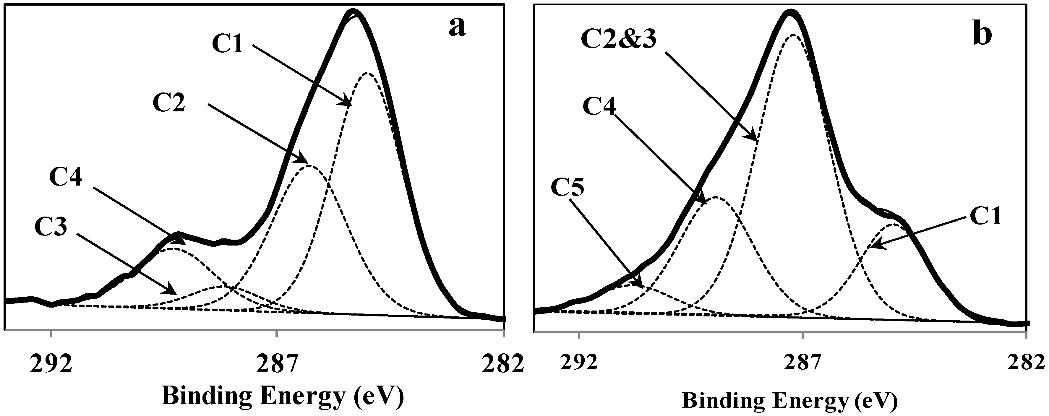
3.1. Surface Chemical Composition of the Fibers

| Sample | Surface composition (%) | ||||
|---|---|---|---|---|---|
| O | C | N | Ca | O/C | |
| Retted fiber | 27.72 | 64.79 | 7.47 | 0.22 | 0.43 |
| Impregnated fiber | 33.73 | 57.37 | 7.49 | 1.41 | 0.59 |

| Item | C1 (C–C, C–H) | C2 (C–O) | C3 (O–C–O) | C4 (O–C=O) | C5 CO32− |
|---|---|---|---|---|---|
| Bindingenergy (eV) | 285 | 286.5 | 288.1 | 289 | 290.8 |
| Retted fiber | 48.73% | 32.35% | 4.79% | 14.13% | 0 |
| Impregnated fiber | 16.69% | 54.58% | 23.25% | 5.47% | |
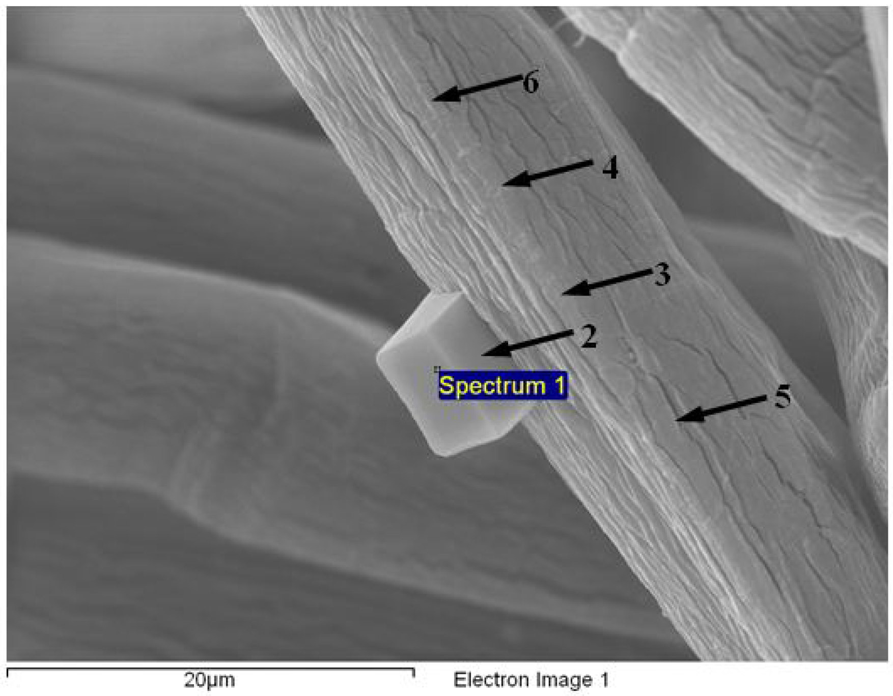
| Spectrum | Element | wt% | at% | CaCO3 wt% | ||||||
|---|---|---|---|---|---|---|---|---|---|---|
| 1 | O | 36.81 | 33.72 | NA | ||||||
| C | 42.50 | 51.86 | NA | |||||||
| N | 10.02 | 10.48 | NA | |||||||
| Ca | 10.52 | 3.85 | 26.27 | |||||||
| 2 | O | 56.57 | 62.48 | NA | ||||||
| C | 17.74 | 26.11 | NA | |||||||
| N | NA | NA | NA | |||||||
| Ca | 25.41 | 11.21 | 63.46 | |||||||
| 3 | O | 34.07 | 29.50 | NA | ||||||
| C | 51.33 | 59.22 | NA | |||||||
| N | 9.56 | 9.46 | NA | |||||||
| Ca | 4.65 | 1.61 | 11.61 | |||||||
| 4 | O | 25.46 | 20.95 | NA | ||||||
| C | 62.26 | 68.24 | NA | |||||||
| N | 11.09 | 10.42 | NA | |||||||
| Ca | 1.19 | 0.39 | 2.97 | |||||||
| 5 | O | 26.08 | 21.87 | NA | ||||||
| C | 58.58 | 65.42 | NA | |||||||
| N | 11.83 | 11.33 | NA | |||||||
| Ca | 2.28 | 0.76 | 5.69 | |||||||
| 6 | O | 26.39 | 22.18 | NA | ||||||
| C | 58.43 | 65.41 | NA | |||||||
| N | 11.61 | 11.15 | NA | |||||||
| Ca | 3.26 | 1.09 | 8.14 | |||||||
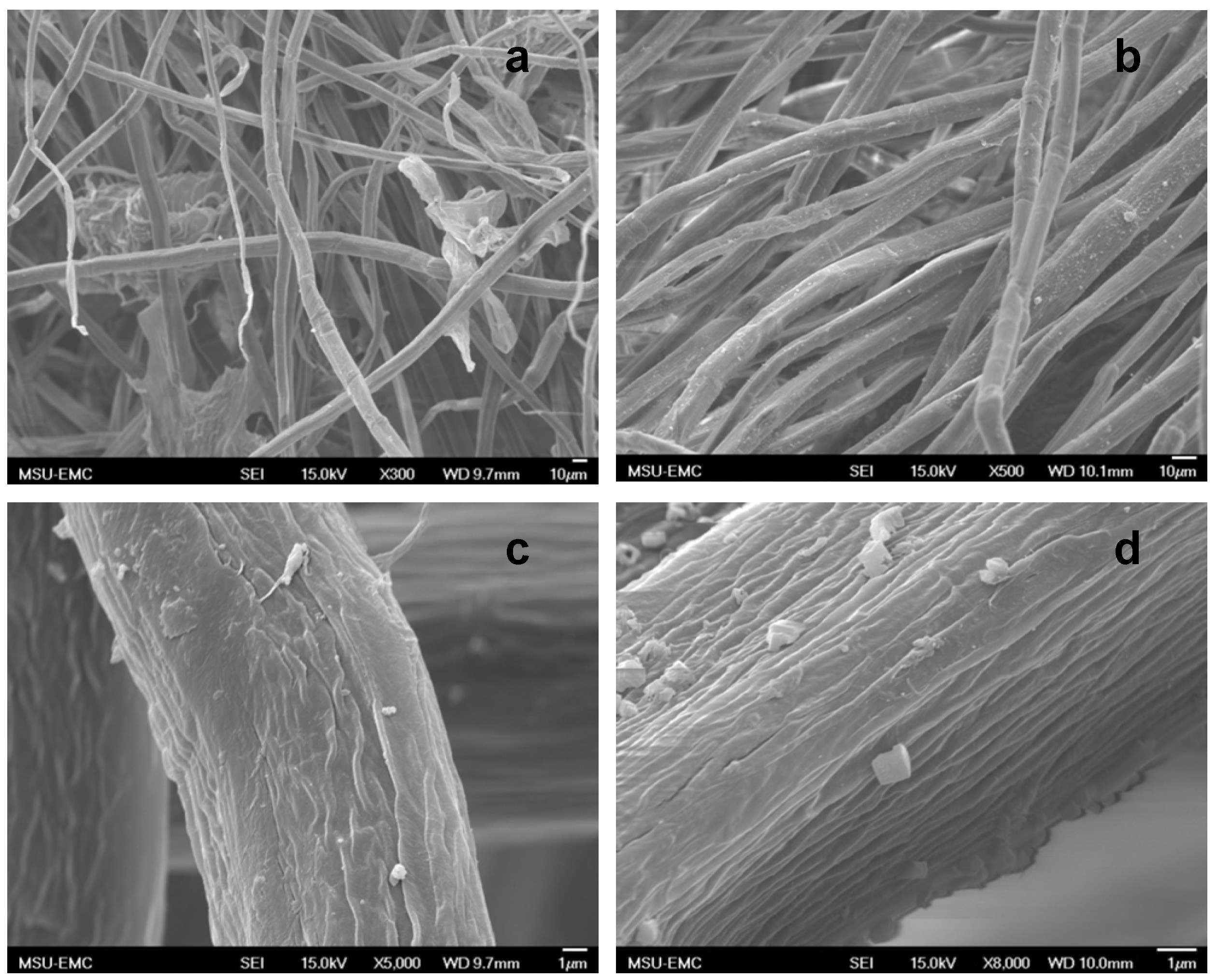
3.2. Scanning Electron Microscopy (SEM) of the Fibers


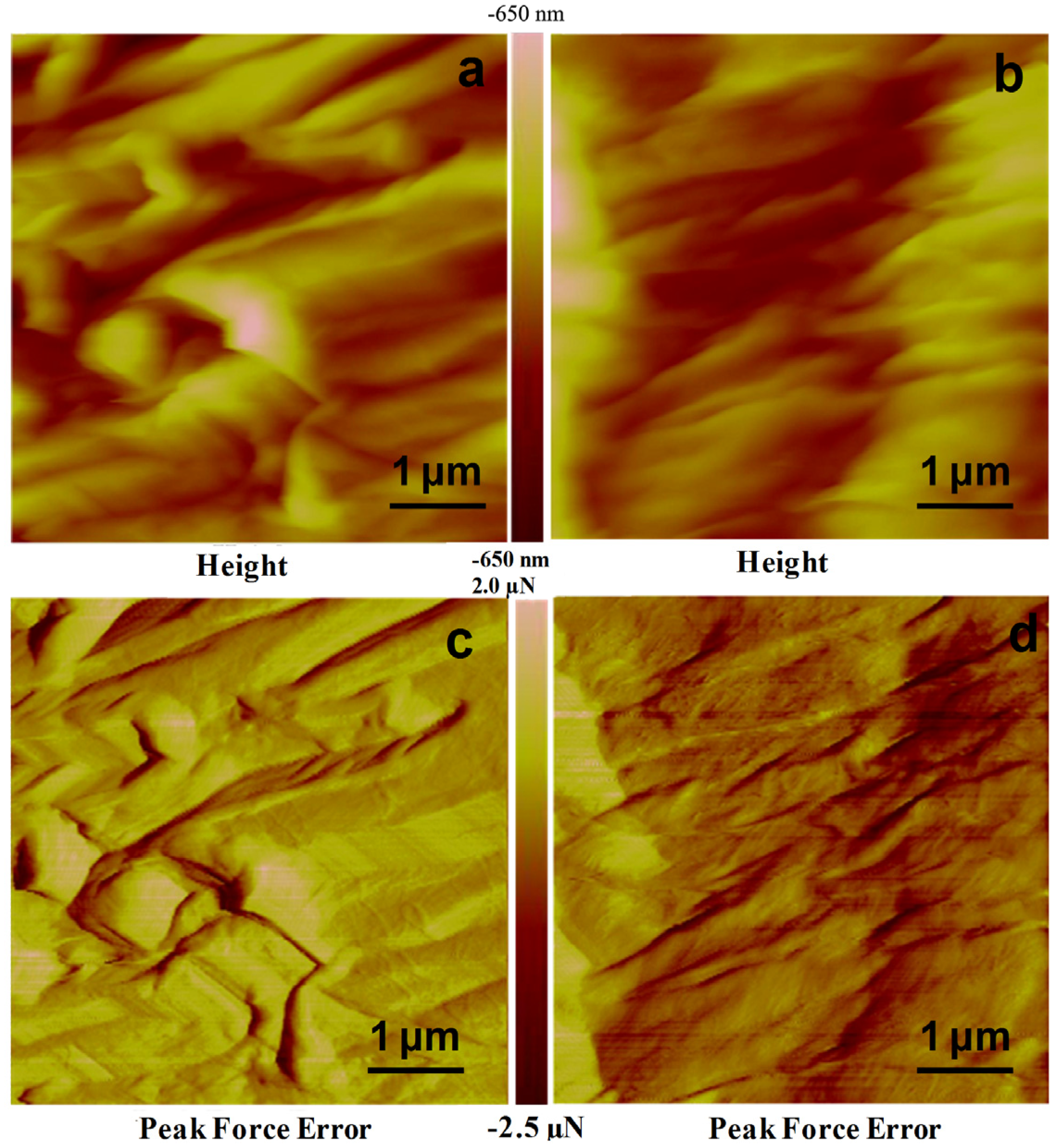
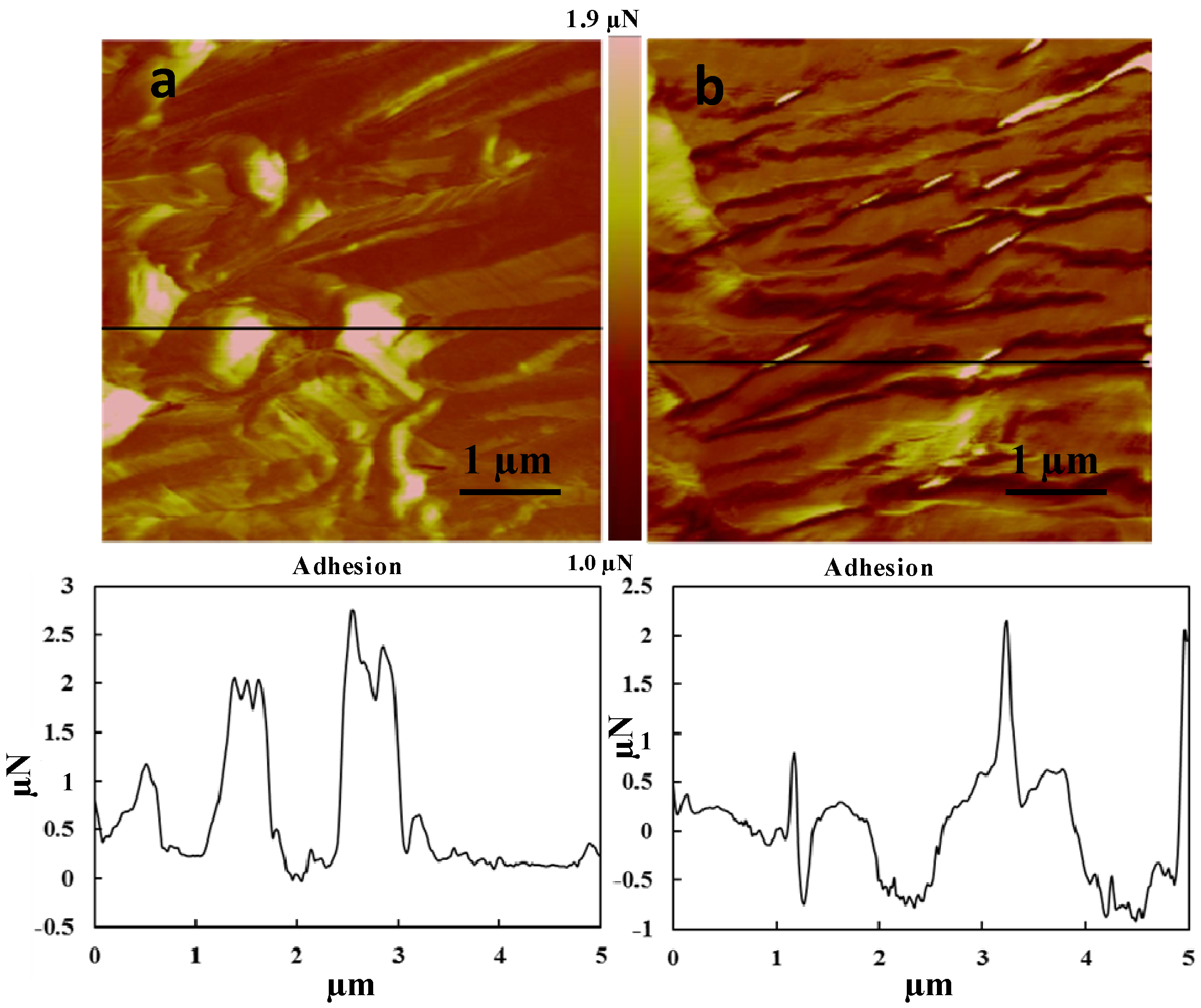
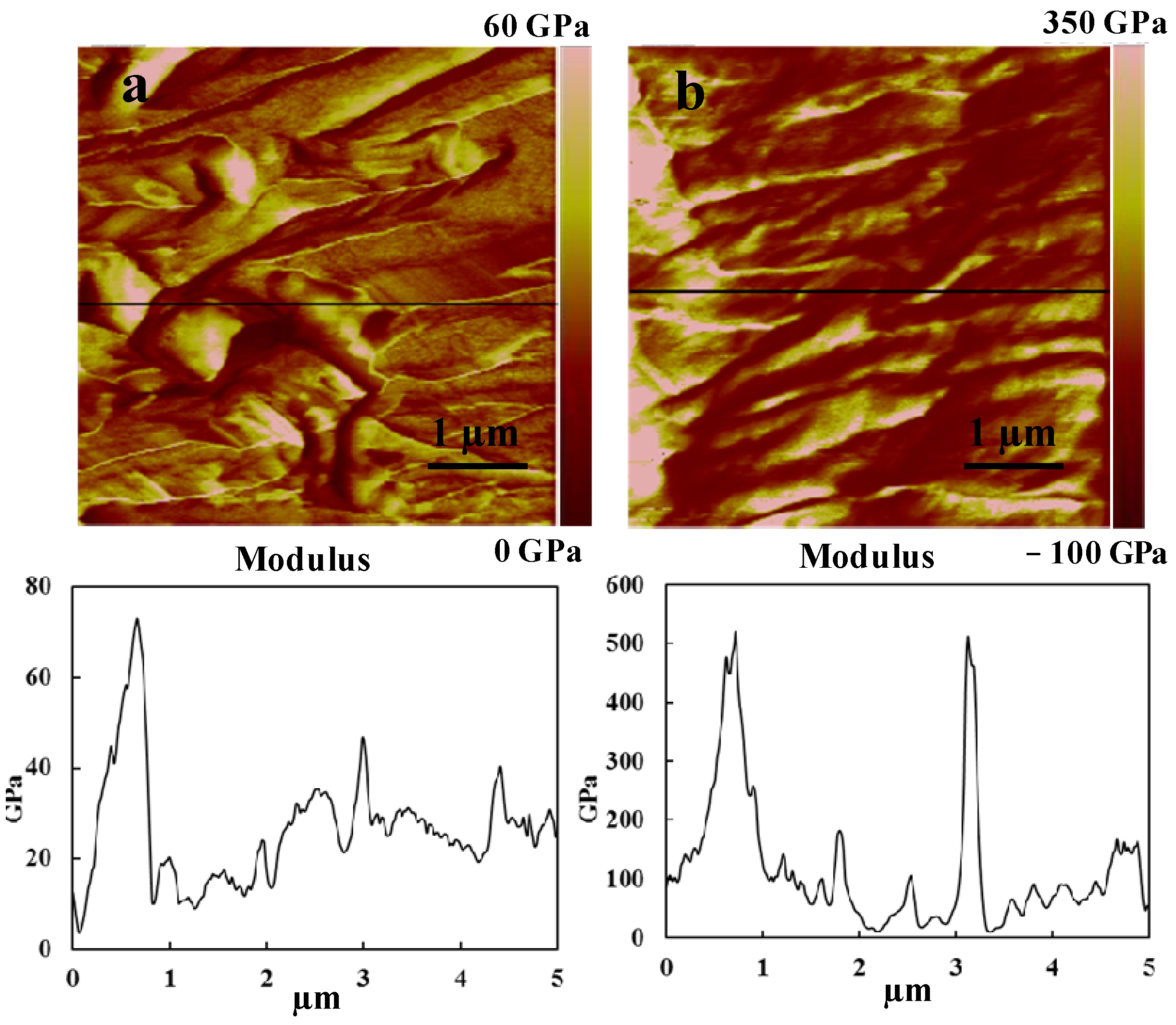
3.3. Atomic Force Microscopy (AFM) of the Fibers
| Sample | Root mean squaresurface roughness (Nm) | Image mean average | |
|---|---|---|---|
| Adhesionn (N) | DMT modulus (GPa) | ||
| Retted fiber | 155 | 387 | 27 |
| Impregnated fiber | 164 | 157 | 120 |


4. Conclusions
Acknowledgments
Author Contributions
Conflicts of Interest
References
- Clemons, C. Wood-plastic composites in the United States: The interfacing of two industries. For. Prod. J. 2002, 6, 10–18. [Google Scholar]
- Serizawa, S.; Inoue, K.; Iji, M. Kenaf-fiber-reinforced poly(lactic acid) used for electronic products. J. Appl. Polym. Sci. 2006, 100, 618–624. [Google Scholar]
- Rymsza, T. Advancements of kenaf in the USA kenaf paper and nonpaper developments. Available online: http://www.visionpaper.com/PDF_speeches_papers/007anwpp.pdf (accessed on 28 May 2012).
- Han, J.S. Properties of Nonwood Fibers. In Proceedings of the Korean Society of Wood Science and Technology Annual Meeting, Seoul, Korea, 24–25 April 1998; pp. 3–12.
- Bolton, A.J. Natural fibers for plastic reinforcement. Mater. Tech. 1994, 9, 12. [Google Scholar]
- Karnani, R.; Krishnan, M.; Narayan, R. Biofiber-reinforced polypropylene composites. Polym. Eng. Sci. 1997, 2, 476–483. [Google Scholar]
- Rana, A.K.; Mandal, A.; Mitra, B.C.; Jacobson, R.; Rowell, R.; Banerjee, A.N. Short jute fiber-reinforced polypropylene composites: Effect of compatibilizer. J. Appl. Polym. Sci. 1998, 69, 329–338. [Google Scholar]
- Eichhorn, S.J.; Baillie, C.A.; Zafeiropoulos, N.; Mwaikambo, L.Y.; Ansell, M.P.; Dufresne, A.; Entwistle, K.M.; Herrera-Franco, P.J.; Escamilla, G.C.; Groom, L.; et al. Review: Current international research into cellulosic fibres and composites. J. Mater. Sci. 2001, 36, 2107–2131. [Google Scholar]
- Sanadi, A.R.; Hunt, J.F.; Caulfield, D.F.; Kovacsvolgyi, G.; Destree, B. High Fiber-Low Matrix Composites: Kenaf Fiber/Polypropylene. In Proceedings of 6th International Conference on Woodfiber-Plastic Composites, Madison, WI, USA, 23–25 May 2002; pp. 121–124.
- Joseph, K.; Thomas, S.; Pavithran, C.; Brahmakumar, M. Tensile properties of short sisal fiber-reinforced polyethylene composites. J. Appl. Polym. Sci. 1993, 47, 1731–1739. [Google Scholar]
- Joseph, P.V.; Joseph, K.; Thomas, S.; Pillai, C.K.S.; Prasad, V.S.; Groeninckx, G.; Sarkissova, M. The thermal and crystallisation studies of short sisal fibre reinforced polypropylene composites. Compos. Part A Appl. Sci. Manuf. 2003, 34, 253–266. [Google Scholar] [CrossRef]
- Tajvidi, M.; Falk, R.H.; Hermanson, J.C. Time–temperature superposition principle applied to a kenaf-fiber/high-density polyethylene composite. J. Appl. Polym. Sci. 2005, 97, 1995–2004. [Google Scholar]
- Espert, A.; Camacho, W.; Karlson, S. Thermal and thermomechanical properties of biocomposites made from modified recycled cellulose and recycled polypropylene. J. Appl. Polym. Sci. 2003, 89, 2353–2360. [Google Scholar]
- Espert, A.; Vilaplana, F.; Karlsson, S. Comparison of water absorption in natural cellulosic fibres from wood and one-year crops in polypropylene composites and its influence on their mechanical properties. Compos. Part A Appl. Sci. Manuf. 2004, 35, 1267–1276. [Google Scholar] [CrossRef]
- Ma, C.G.; Rong, M.Z.; Zhang, M.Q.; Friedrich, K. Irradiation-induced surface graft polymerization onto calcium carbonate nanoparticles and its toughening effects on polypropylene composites. Polym. Eng. Sci. 2005, 45, 529–538. [Google Scholar]
- Rout, J.; Misra, M.; Tripathy, S.S.; Nayak, S.K.; Mohanty, A.K. The influence of fibre treatment on the performance of coir-polyester composites. Compos. Sci. Technol. 2001, 61, 1303–1310. [Google Scholar]
- Yuan, X.; Jayaraman, K.; Bhattacharyya, D. Effects of plasma treatment in enhancing the performance of woodfibre-polypropylene composites. Compos. Part A Appl. Sci. Manuf. 2004, 35, 1363–1374. [Google Scholar] [CrossRef]
- Kalia, S.; Kaith, B.S.; Kaur, I. Pretreatments of natural fibers and their application as reinforcing material in polymer composites—A review. Polym. Eng. Sci. 2009, 49, 1253–1272. [Google Scholar]
- Allan, G.G.; Carroll, J.P.; Negri, A.R.; Raghuraman, M.; Ritzenthaler, P.; Yahiaoui, A. The microporosity of pulp: the precipitation of inorganic fillers within the micropores of the cell wall. Tappi. J. 1992, 75, 175–178. [Google Scholar]
- Shi, J.; Shi, S.Q.; Barnes, H.M.; Horstemeyer, M.; Wang, G. Kenaf bast fibers—Part II: Inorganic nanoparticle impregnation for polymer composites. Int. J. Polym. Sci. 2011, 2011, 736474. [Google Scholar] [CrossRef]
- Shi, S.Q.; Lee, S.; Horstemeyer, M. Natural Fiber Retting and Inorganic Nanoparticle Impregnation Treatment for Natural Fiber/Polymer Composites. In Proceedings of the American Society for Composites, University of Washington, Seattle, WA, USA, 19 September 2007.
- Lee, S.; Shi, S.Q.; Barnes, M.H. Multifunctional Nanoparticles at the Hydrophilic and Hydrophobic Interface. In Proceedings of Advanced Biomass Science and Technology for Bio-Based Products, Chinese Academy of Forestry, Beijing, China, 23–25 May 2009; pp. 173–181.
- Cranston, E.D.; Eita, M.; Johansson, E.; Netrval, J.; Salajková, M.; Arwin, H.; Wågberg, L. Determination of Young’s modulus for nanofibrillated cellulose multilayer thin films using buckling mechanics. Biomacromolecules 2011, 12, 961–969. [Google Scholar]
- John, M.J.; Thomas, S. Biofibres and biocomposites. Carbohydr. Polym. 2008, 71, 343–364. [Google Scholar]
- Pommet, M.; Juntaro, J.; Heng, J.Y.Y.; Mantalaris, A.; Lee, A.F.; Wilson, K.; Kalinka, G.; Shaffer, M.S.P.; Bismarck, A. Surface modification of natural fibers using bacteria: Depositing bacterial cellulose onto natural fibers to create hierarchical fiber reinforced nanocomposites. Biomacromolecules 2008, 9, 1643–1651. [Google Scholar]
- Sgriccia, N.; Hawley, M.C.; Misra, M. Characterization of natural fiber surfaces and natural fiber composites. Compos. Part A Appl. Sci. Manuf. 2008, 39, 1632–1637. [Google Scholar] [CrossRef]
- Csiszár, E.; Fekete, E. Microstructure and surface properties of fibrous and ground cellulosic substrates. Langmuir 2011, 27, 8444–8450. [Google Scholar]
- Pothan, L.A.; Simon, S.S.; Thomas, S. XPS studies of chemically modified banana fibers. Biomacromolecules 2006, 7, 892–898. [Google Scholar]
- Koinkar, V.N.; Bhushan, B. Effect of scan size and surface roughness on microscale friction measurements. J. Appl. Phys. 1997, 81, 2472–2479. [Google Scholar]
- Butt, H.J.; Cappella, B.; Kappl, M. Force measurements with the atomic force microscope: Technique, interpretation and applications. Surf. Sci. Rep. 2005, 59, 1–152. [Google Scholar]
- Bhushan, B.; Sundararajan, S. Micro/nanoscale friction and wear mechanisms of thin films using atomic force and friction force microscopy. Acta Mater. 1998, 46, 3793–3804. [Google Scholar]
- Sedin, D.L.; Rowlen, K.L. Adhesion forces measured by atomic force microscopy in humid air. Anal. Chem. 2000, 72, 2183–2189. [Google Scholar] [CrossRef]
- Shi, J.; Shi, S.Q.; Barnes, H.M.; Pittman, C.U. A chemical process for preparing cellulosic fibers hierarchically from kenaf bast fibers. BioResources 2011, 6, 879–890. [Google Scholar]
- Materials data from Crystan Ltd. Poole. UK. Calcite (CaCO3) Data Sheet. Available online: http://www.crystran.co.uk/uploads/files/106.pdf (accessed on 18 August 2011).
© 2014 by the authors; licensee MDPI, Basel, Switzerland. This article is an open access article distributed under the terms and conditions of the Creative Commons Attribution license (http://creativecommons.org/licenses/by/3.0/).
Share and Cite
Liang, K.; Shi, S.Q.; Wang, G. Effect of Impregnated Inorganic Nanoparticles on the Properties of the Kenaf Bast Fibers. Fibers 2014, 2, 242-254. https://doi.org/10.3390/fib2030242
Liang K, Shi SQ, Wang G. Effect of Impregnated Inorganic Nanoparticles on the Properties of the Kenaf Bast Fibers. Fibers. 2014; 2(3):242-254. https://doi.org/10.3390/fib2030242
Chicago/Turabian StyleLiang, Kaiwen, Sheldon Q. Shi, and Ge Wang. 2014. "Effect of Impregnated Inorganic Nanoparticles on the Properties of the Kenaf Bast Fibers" Fibers 2, no. 3: 242-254. https://doi.org/10.3390/fib2030242
APA StyleLiang, K., Shi, S. Q., & Wang, G. (2014). Effect of Impregnated Inorganic Nanoparticles on the Properties of the Kenaf Bast Fibers. Fibers, 2(3), 242-254. https://doi.org/10.3390/fib2030242