
3D FE Analysis of RC Beams Externally Strengthened with SRG/SRP Systems


Department of Civil Engineering, University of Calabria, Via P. Bucci, Cubo 39B, Rende, Cosenza 87036, Italy
*
Author to whom correspondence should be addressed.
Fibers 2016, 4(2), 19; https://doi.org/10.3390/fib4020019
Submission received: 18 December 2015
/
Accepted: 11 May 2016
/
Published: 26 May 2016
(This article belongs to the Special Issue Fiber Reinforced Cementitious Matrix (FRCM) as Strengthening Systems of Existing Masonry and Concrete Structures)
Abstract
:The purpose of this study is to evaluate, through a nonlinear Finite Element (FE) analysis, the structural behavior of Reinforced Concrete (RC) beams externally strengthened by using Steel Reinforced Grout (SRG) and Steel Reinforced Polymer (SRP) systems. The parameters taken into account were the external strengthening configuration, with or without U-wrap end anchorages, as well as the strengthening materials. The numerical simulations were carried out by using a three-dimensional (3D) FE model. The linear and nonlinear behavior of all materials was modeled by appropriate constitutive laws and the connection between concrete substrate and external reinforcing layer was simulated by means of cohesive surfaces with appropriate bond-slip laws. In order to overcome convergence difficulties, to simulate the quasi-static response of the strengthened RC beams, a dynamic approach was adopted. The numerical results in terms of load-displacement curves, failure modes, and load and strain values at critical stages were validated against some experimental data. As a result, the proposed 3D FE model can be used to predict the structural behavior up to ultimate stage of similar strengthened beams without carrying out experimental tests.
1. Introduction
In the last three decades the need to repair and rehabilitate existing reinforced concrete (RC) has become an increasingly important challenge for civil engineering. Amongst various methods developed for the strengthening and retrofitting of RC beams, the external bonding of Fiber Reinforced Polymer (FRP) composite materials has been widely accepted as an effective and convenient method [1,2,3]. Recent developments in the use of these strengthening systems have heightened the need to carry out reliable numerical analyses based on the Finite Element (FE) method capable of predicting the behavior of strengthened structural elements at all stages of loading up to failure. There are numerous studies available in the literature regarding the numerical modeling of RC beams strengthened to shear and/or to flexure with FRP systems [4,5,6,7,8].
Recently, a new composite class of materials has been developed and proposed in the market. This new composite material consists of an unidirectional Ultra High Tensile Steel Strength (UHTSS) fabric/strip which can be embedded in an inorganic matrix (SRG: Steel Reinforced Grout) or in an organic matrix (SRP: Steel Reinforced Polymer). These systems are capable of ensuring the same advantages of FRP strengthening systems, in terms of easiness of application, low invasiveness, and reduced intervention time, but with a lower cost, better fire resistance, and a higher compatibility with existing structures, compared to FRP materials [9,10]. The properties and potential applications of these new materials have been analyzed in some experimental investigations [11,12,13,14,15,16,17,18,19,20,21,22], but few of the studies are concerning the numerical modeling of structural elements strengthened with them [23].
In order to carry out analytical and numerical (FE) analyses of SRG/SRP strengthened RC members specific analytical tools [24] and bond-slip models [23], should be used, respectively. Until today, standards and guidelines addressed to SRG/SRP systems were not yet available and should be defined.
In this work, the structural behavior of SRG/SRP strengthened RC beams under monotonic loads, with or without U-wrap end anchorages, was simulated by using a 3D Finite Element (FE) model. To model concrete-external reinforcement interface some FRP-concrete bond-slip laws, calibrated and validated by Bencardino and Condello [23] for SRG/SRP systems, were adopted. The purpose was to also assess the adaptability of these bond-slip laws to SRG/SRP strengthened RC beams with U-wrap end anchorages. Furthermore, to overcome convergence difficulties due to crack propagation and/or strain softening, such as concrete cracking and debonding phenomena, a dynamic analysis approach was used. Comparisons between numerical results and some experimental data highlighted the reliability and accuracy of the proposed 3D FE model.
2. Experimental Program
The 3D FE model has been defined and used to analyze the behavior of five prototypes tested at the “Laboratory of Materials and Structural Testing” of the University of Calabria [12,13].
Details about the geometry and mechanical properties of the tested specimens, the strengthening layouts, and the test setup are given in the following sections.
2.1. Beam Prototypes
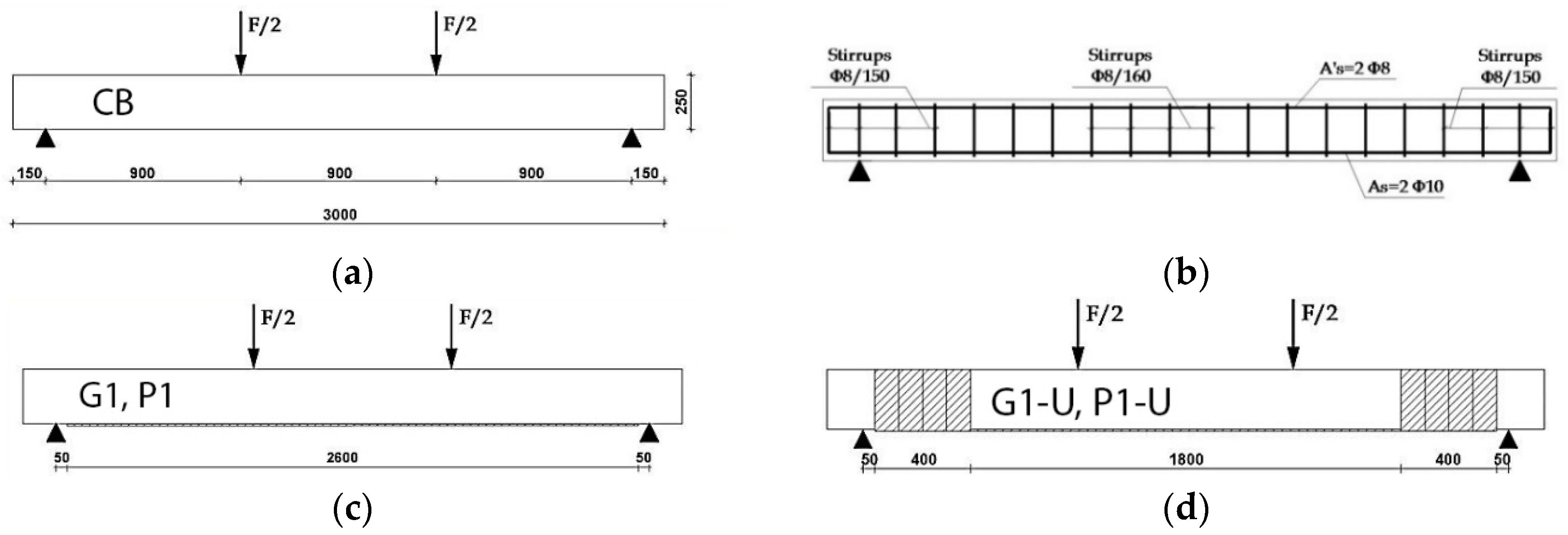
The experimental investigation was carried out on two groups of RC beams externally strengthened in flexure with a layer of unidirectional steel strip. The variable parameters were the type of strengthening system and the use or not of external U-wrap end anchorages. Specifically, two beams of the first group were externally strengthened with a SRG system, one beam with additional external U-wrap end anchorages (G1-U) and one beam simply plated (G1); two beams of the second group were externally strengthened by using a SRP system, one beam with U-wrap end anchorages (P1-U) and another one without additional U-wrap end anchorages (P1). One un-strengthened RC beam was tested as a control beam (CB). Each U-wrap end anchorage was made of four strips side by side, U shaped, each one of 100 mm width applied on a total length of 400 mm. The material used was SRG or SRP according to the system used to strengthen the beam.
All the beams had a rectangular cross-section of 150 mm × 250 mm and were 3000 mm long. They had identical longitudinal and transversal internal steel reinforcements. In fact, they were internally strengthened with 2–10 mm and 2–8 mm diameter longitudinal steel bars at the tension face and at the compression face, respectively, with a clear cover concrete of 20 mm and an effective depth of 217 mm. All the beams were provided with 8 mm diameter vertical stirrups spaced at 150 mm center-to-center. The details of the beams with reference to their geometry and internal/external reinforcements are shown in Figure 1.
2.2. Test Setup and Instrumentation
The beams were internally and externally instrumented and tested under four points bending. Two vertical loads were applied symmetrically to the mid-span of the beams with a constant bending moment region and a constant shear span of 900 mm (Figure 1a). All the beams were simply supported with an effective span of 2700 mm and tested with a shear span to depth ratio of 4.15.
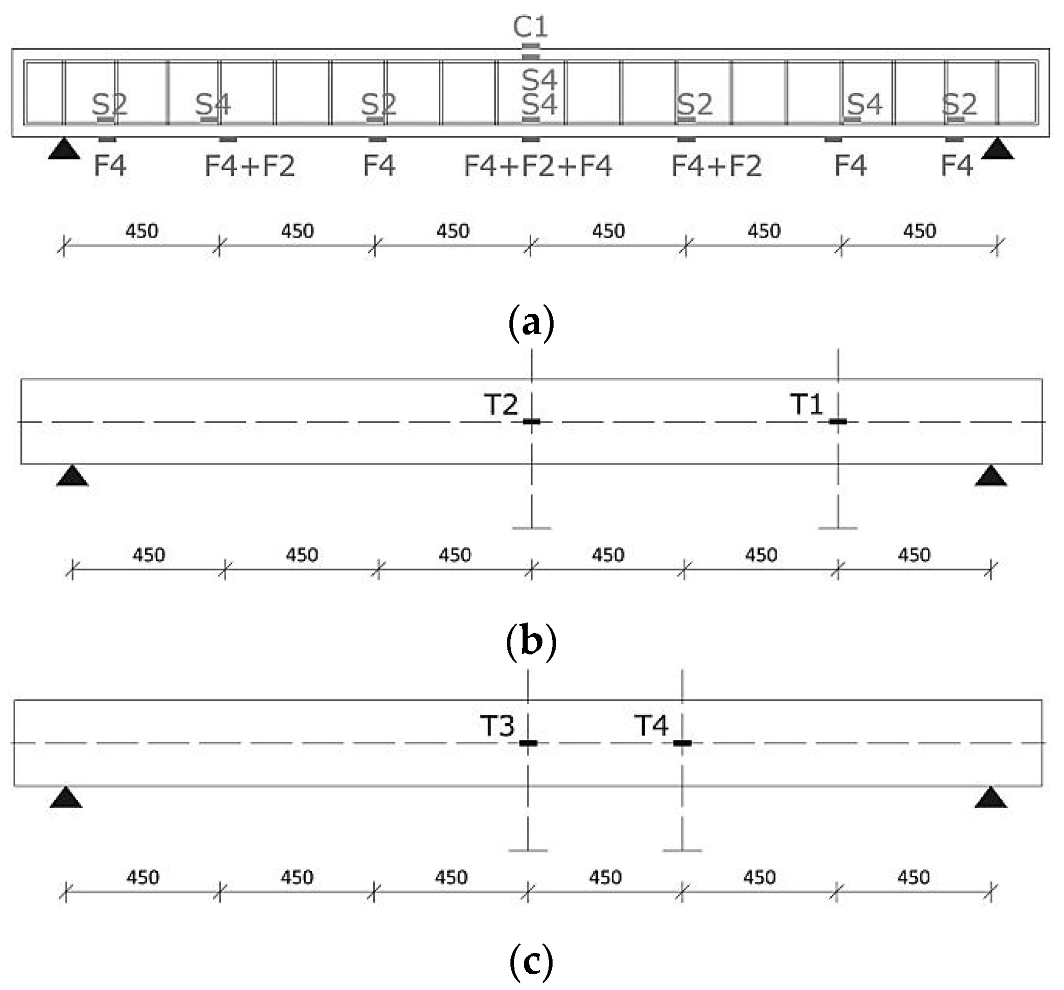
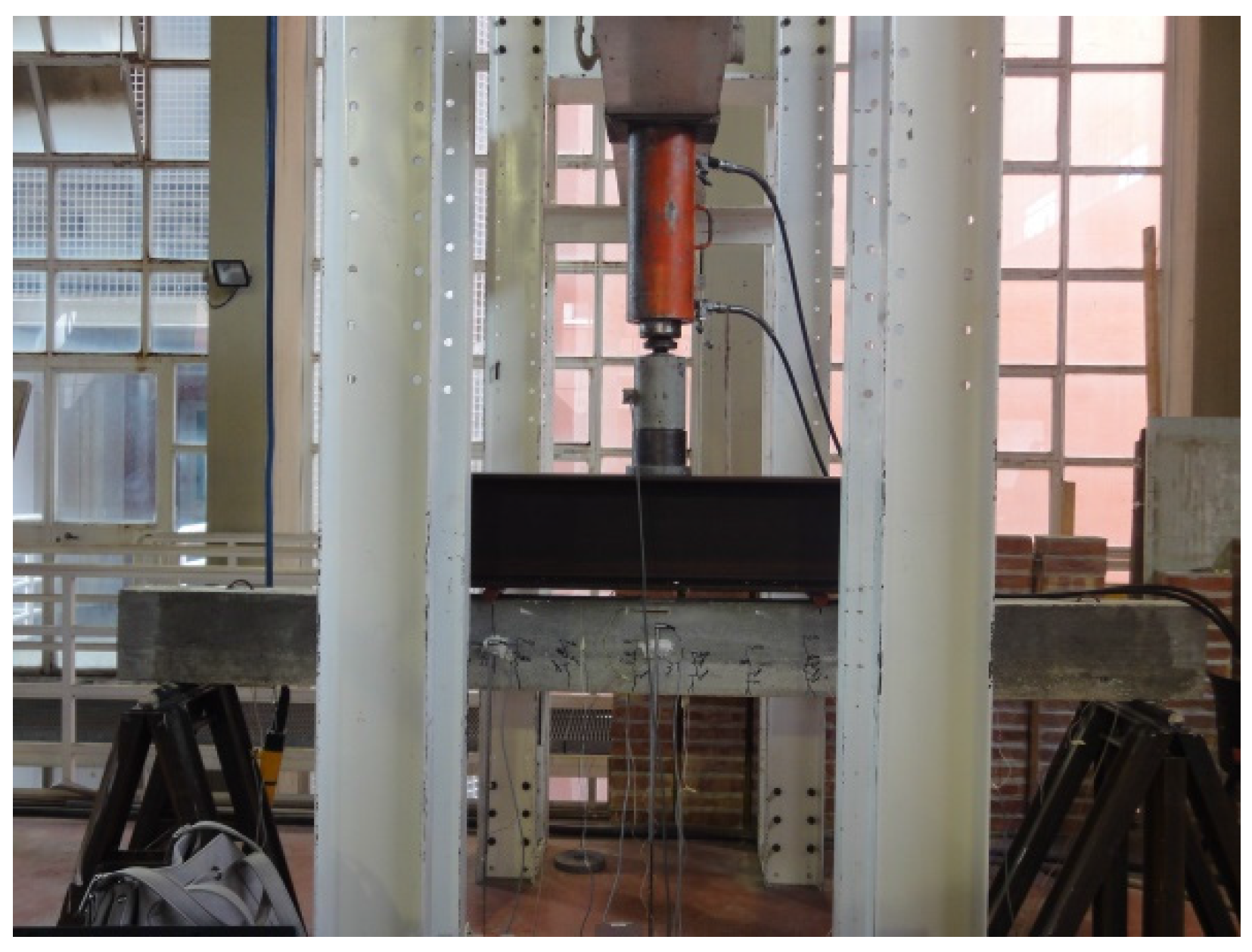
Applied load, vertical displacements, and strains of all the materials were monitored throughout the tests (Figure 2). Displacements were measured at mid-span (T2 and T3), under the applied loads (T4), and at half of the shear spans (T1) by using Linear Variable Displacement Transducers (LVDTs). In order to measure the strain of the materials, ten strain gauges were attached to the internal reinforcing bars (S2 and S4) whereas two strain gauges were placed onto the compression zone of the top concrete surface (C1). Also, the strains on the strengthening systems were monitored and recorded using eleven strain gauges. They were distributed along the length of the strip, some applied on the strip (F2) and others embedded into the matrix (F4). The load was applied monotonically to the beams by means of a hydraulic actuator and recorded using a 300 kN load cell. All the data obtained from the load cell, strain gauges, and LVDTs were recorded through a data acquisition system. During the tests, the load was periodically paused in order to identify and mark crack formations and growth. Figure 2a–c show the instrumentation details used during the tests. The test setup is shown in Figure 3.
2.3. Material Properties
The concrete compression cylinder strength was evaluated with testing over 28 days carried out on six cylindrical samples (150 mm × 300 mm). The average concrete cylinder strength (fcm) was 34.0 MPa. Splitting tensile tests were also carried out over 28 days on six cylindrical samples (150 mm × 300 mm) and the average tensile split strength (fctm) was 3.5 MPa.
The mechanical properties of the internal longitudinal and transversal ribbed steel reinforcing bars were experimentally evaluated. The results, obtained as the average value on three samples, are given in Table 1. The properties of the steel strengthening strip, provided by the manufacturer and/or trading company [25] are given in Table 2.
2.4. Surface Preparation, Matrix, and Bonding Procedure
After the concrete was cast in the mold the RC beams were kept under saturated sand for 28 days. Before bonding of the external reinforcement system to the beams, the bottom surface of each beam was carefully cleaned in order to remove dust, loose parts, oil stains, and other parts that could affect the bonding. The concrete surface was subjected to moist sandblasting and hydraulic scouring. To obtain a good adhesion, the primer, a bi-component epoxy resin, was applied. Once the reinforcing strip was lying on concrete surface, with reference to the specific strengthening system, the selected matrix was poured. For the SRG system the mortar mixed to 30% by weight with a synthetic resin that was used. The binder (a ready-to-use fine granulometry mortar made from selected hydraulic binders) was mixed for two minutes with ¾ synthetic resin, using a drill and whip, and then the binder and the remaining liquid were continuously poured and mixed until the desired consistency was obtained. For the SRP system the mortar with two component epoxy resin was used. In this case, the two components were thoroughly mixed with a drill at low speed (200–300 turns/min) until a perfect blend was obtained, then the binder was added with a ratio of 15 kg for every 6 kg of epoxy resin. The matrix was applied to the substrate using a smooth metal trowel in order to obtain a layer that was about 2–3 mm thick. The fabric strip was placed on it and pressed lightly using a metal spreader to ensure the fabric sank completely into the matrix. A second layer of matrix that was about 2–3 mm thick was applied to cover the reinforcing mesh completely. The main properties of the matrix, for the SRG and SRP systems provided by the manufacturer and/or trading company [25], are given in Table 3.
3. FE Modeling
3.1. Geometry
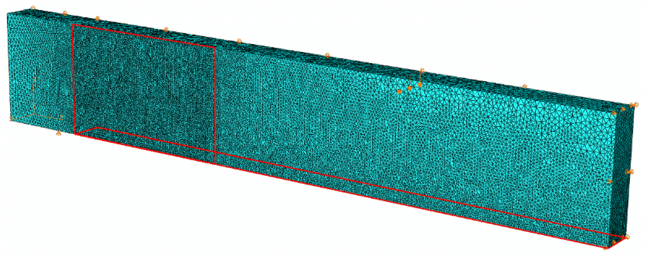
The numerical analysis was carried out by using the FE software package ABAQUS/Explicit [26]. For the geometrical, mechanical, and loading symmetry of the beams (Figure 1) a quarter of the system was modeled. Kinematically, at the symmetry planes of the model each node was not allowed horizontal translation, whereas at the nodes corresponding to the lateral support the vertical displacement was locked. A view of the FE mesh is given in Figure 4.
The concrete, internal steel bars, and external reinforcement were modeled by using the C3D4 linear tetrahedron FE, T3D2 linear truss FE, and S4 shell FE, respectively. Cohesive surfaces, defined through a general contact, were used for modeling of the concrete-external reinforcement interface.
The nonlinear FE analysis was carried out with the displacement control method, so that the softening branch of the load-midspan deflection curve and the debonding process could be followed.
3.2. Material Models
3.2.1. Concrete, Steel, SRG, and SRP Systems
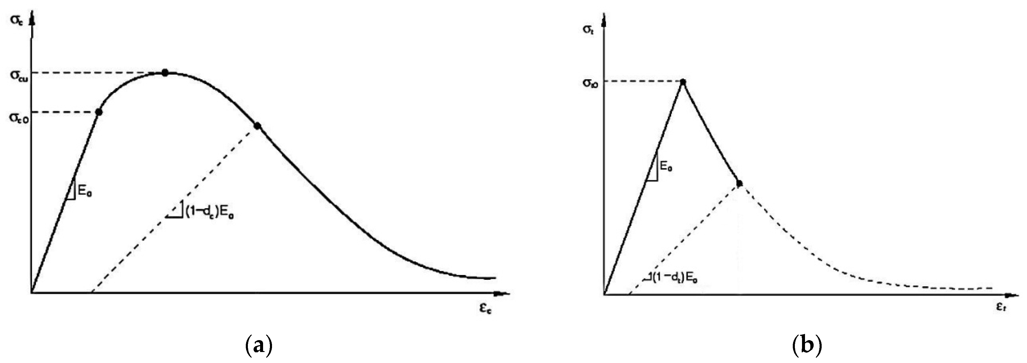
In order to model the behavior of the concrete the “concrete damage plasticity” was used [27,28]. It assumes that the main two failure mechanisms are tensile cracking and compressive crushing of the concrete material. In the linear elastic range the behavior was defined by the elastic modulus (E0 = 31758 MPa) calculated according to Eurocode 2 [29], and the Poisson’s ratio (0.2). In the plastic range damage parameters, a description of tensile/compressive behavior were requested. The five plastic damage parameters were: the dilation angle (38°), the flow potential eccentricity (0.1), the ratio of initial biaxial compressive yield stress to initial uniaxial compressive yield stress (1.16), the ratio of the second stress invariant on the tensile meridian to that on the compressive meridian (0.667), and the viscosity parameter (0.0) [26,27,28]. The concrete compressive behavior was modeled with the well-known stress-strain relationship proposed by Hognestad [30], with the ultimate compressive strain equal to 0.0035. The concrete tensile behavior was modeled by using a linear elastic branch until tensile strength (3.5 MPa). After crack initiation the linear softening was started. The post-failure behavior for direct straining was modeled with tension stiffening, which granted to ability to define the post-failure stress-strain relationship for cracked concrete. The ultimate tensile strain at the end softening was set to 0.001. The responses of the concrete to compression and tension uniaxial loading are shown in Figure 5a,b, respectively; where σc0 is the maximum compressive elastic stress (assumed 0.3fcm), σcu is the compressive strength (σcu = fcm), σt0 is the tensile strength (σt0 = fctm), and dc and dt are the compressive and tensile damage parameters (dc = 1 − σc/fcm, dt = 1 − σt/fctm), respectively.
The longitudinal and transversal steel bars were modeled with a bilinear elastic-perfectly plastic model. In the linear elastic range the behavior was defined by the Young modulus (210,000 MPa) and the Poisson’s ratio (0.3); whereas in the plastic range it was modeled according to the Von Mises criterion defined through the yielding strength (Table 1) and the ultimate plastic strain (0.2).
The external strengthening system, consisting of multi-filament yarns embedded in organic (SRP) or inorganic (SRG) matrix, was modeled as homogeneous material. In fact, the mechanical behavior of the SRG (or SRP) system is orthotropic, but for the geometrical, mechanical, and loading symmetry of the beams, the strain in the external reinforcement was relevant only in the longitudinal direction. In this particular case a brittle elastic isotropic model can be used. The input parameters were: elastic modulus (206,000 MPa), Poisson’s ratio (0.3), and ultimate tensile strength (2950 MPa).
In order to carry out a dynamic analysis, the density parameters of the materials were required. Specifically, they were assumed equal to 2.5 × 10⁻⁹ t/mm3 and 7.85 × 10⁻⁹ t/mm3 for concrete and internal steel bars/external strengthening system, respectively.
3.2.2. Interface Model and Bond-Slip Laws
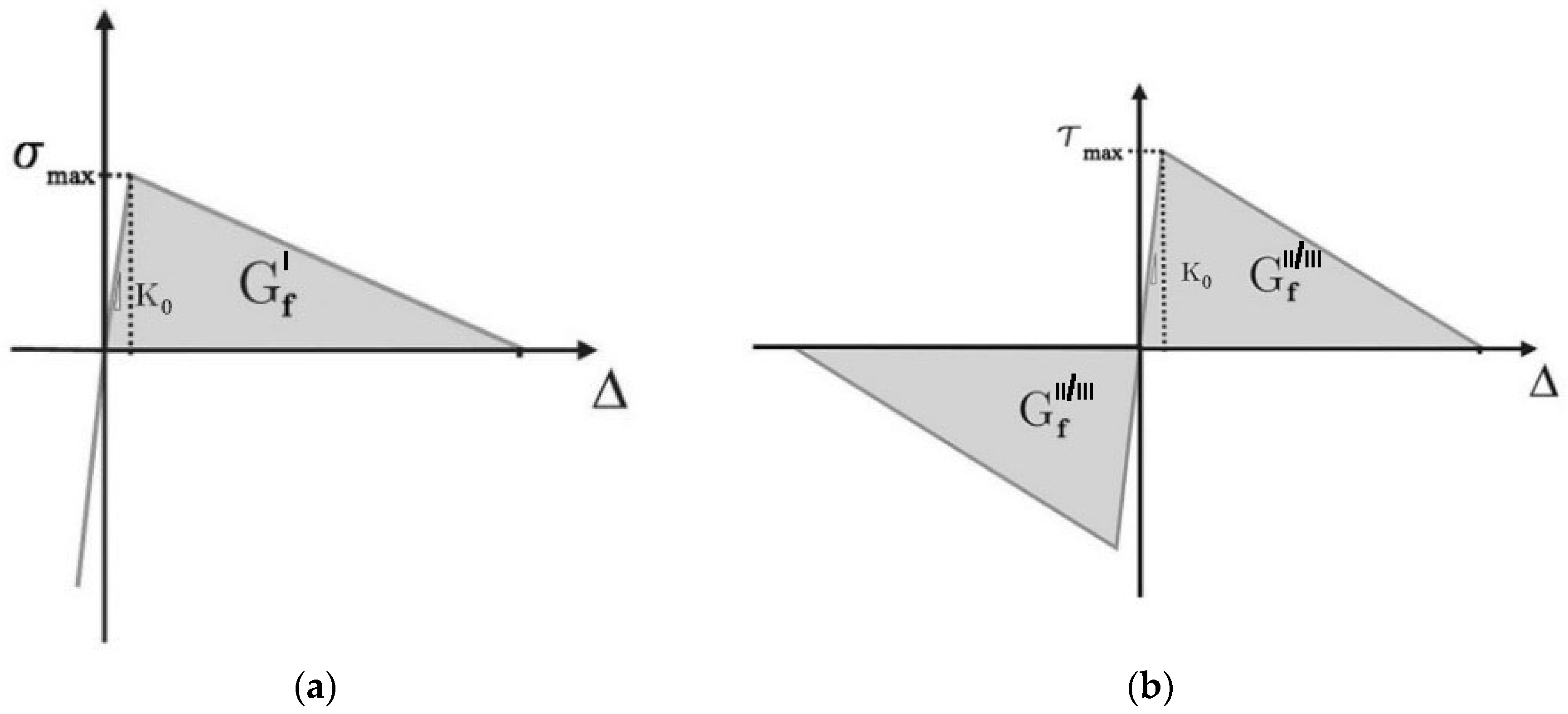
In order to simulate the SRG/SRP-concrete interface cohesive surfaces were defined. The model determines the potential surfaces of separation and describes their interaction by defining a relative displacement at each contact point (traction-separation approach) [31,32]. The traction-separation model was assumed to be bi-linear with initially linear elastic behavior followed by the initiation of damage, modeled by a linear softening branch. It is characterized by three failure modes: opening (mode I), sliding I (mode II), and sliding II (mode III); the first is due to normal stresses, whereas the other two depend on the shear stresses. The cohesive surfaces were defined as the interface connections between the SRG/SRP layer and concrete substrate, at the bottom face and in the U-wrap end anchorage regions.
The damage initiation was assumed to occur when a quadratic function involving the normal and shear stress ratios becomes equal to the unitary value:
Here σ, τs , and τt are the normal (mode I) and shear (modes II, III) stresses at the interface. The σmax and τmax are the maximum stresses in normal and shear directions, respectively. The symbol “
” represents the Macaulay bracket (a pure compressive stress state does not initiate damage). A linear softening model expressed in terms of energy release was used to describe the damage evolution. The dependence of the fracture energy on the mixed mode was based on the power law fracture criterion. It states that failure under mixed-mode conditions is governed by a power law interaction of the energy required to cause failure in the individual (opening, sliding I, and sliding II) modes, given by:
In the expression above the quantities Gn, Gs, and Gt refer to the work done by the traction and its conjugate relative displacement in the normal (mode I) and shear (modes II, III) directions. The quantities GfI, GfII, and GfIII are the critical fracture energies required to cause failure in the normal (mode I) and shear (modes II, III) directions (in this study GfII = GfIII = Gf). The value of the power parameter α was set to 2.0. Figure 6a,b show the traction-separation responses for mode I and modes II/III, respectively.
The numerical simulations should be carried out by using specific SRG/SRP-concrete bond-slip laws. However, appropriate bond-slip laws capable to predict the structural behavior of strengthened RC elements are not yet available in the literature for inorganic based strengthening systems. Nevertheless, the reliability and adaptability of some bond-slip laws [33,34,35,36] proposed for the FRP systems to predict the behavior of RC beams externally simple plated with SRG and SRP systems was recently analyzed by Bencardino and Condello [23]. The study concludes that among a set of bi-linear FRP-concrete bond-slip laws, the Lu et al. [35] bond-slip model was also suitable to simulate the behavior of a SRG-concrete interface. For the SRP-concrete interface a modification of the same bond–slip law was proposed, calibrated, and validated against the available experimental data [23]. The input parameters for SRG/SRP-concrete interface, used in this study, are given in Table 4 (K0 is the initial stiffness, τmax is the shear bond strength, and Gf is the fracture energy). They were assigned to both sliding I and sliding II fracture modes. With reference to the mode I, for both the SRG-concrete and SRP-concrete interfaces, the maximum stress σmax was set to the concrete tensile strength (3.5 MPa) and the fracture energy was assumed to be 10% of Gf [33]. Further details regarding the relationships used to calculate and calibrate the interface parameters are given in [23].
3.3. Solution Technique
In the modeling of structures made of brittle materials, such as concrete and masonry, unstable structural responses due to crack propagation and/or strain softening can often occur, making it difficult for common static solution strategies, such as the Newton–Raphson or arc-length methods, to obtain a converged solution. These numerical difficulties develop due to localized damage. In these cases, the displacements of the nodes around the damage zones dominate the norm of the displacement increment and the failure process cannot be sensitively reflected by the global norm of displacement. Therefore, to solve quasi-static problems with strong strain localization phenomena, such as concrete cracking and debonding processes, some researchers have used dynamic methods [23,37].
In this study a special purpose FE procedure, that employs an explicit integration scheme to solve highly nonlinear systems, was used. As a result of the central difference method being used to integrate the equilibrium equations in the time domain, the discrete mass matrix plays a crucial role in both computational efficiency and accuracy. To improve the computational efficiency the variable mass scaling was used at the beginning of each step with a fixed time increment equal to 0.00005 in all regions of the model. For this time increment the kinetic energy was a small fraction of the internal energy of the model (less than 5%) and hence the simulations were quasi-static.
Preliminary results obtained with a rather coarse mesh showed inaccuracy due to excessive distortions of the finite element C3D4 in the tensile concrete region, whereas the results obtained from a fine mesh were more accurate. Further refinements have shown the same result as the previous mesh but more time was needed for computations. Therefore, a mapped fine mesh was finally chosen. The minimum and maximum sizes of the FE were equal to 5.0 mm and 15.0 mm, respectively, for the concrete and 5.0 mm for the internal and external reinforcements. The solution time with this mesh was approximately 10–12 h, using processor Intel(R) Xeon(R) W3565 (3.20 GHz) (SiComputer, Lugo, Italy).
4. Numerical/Experimental Comparisons
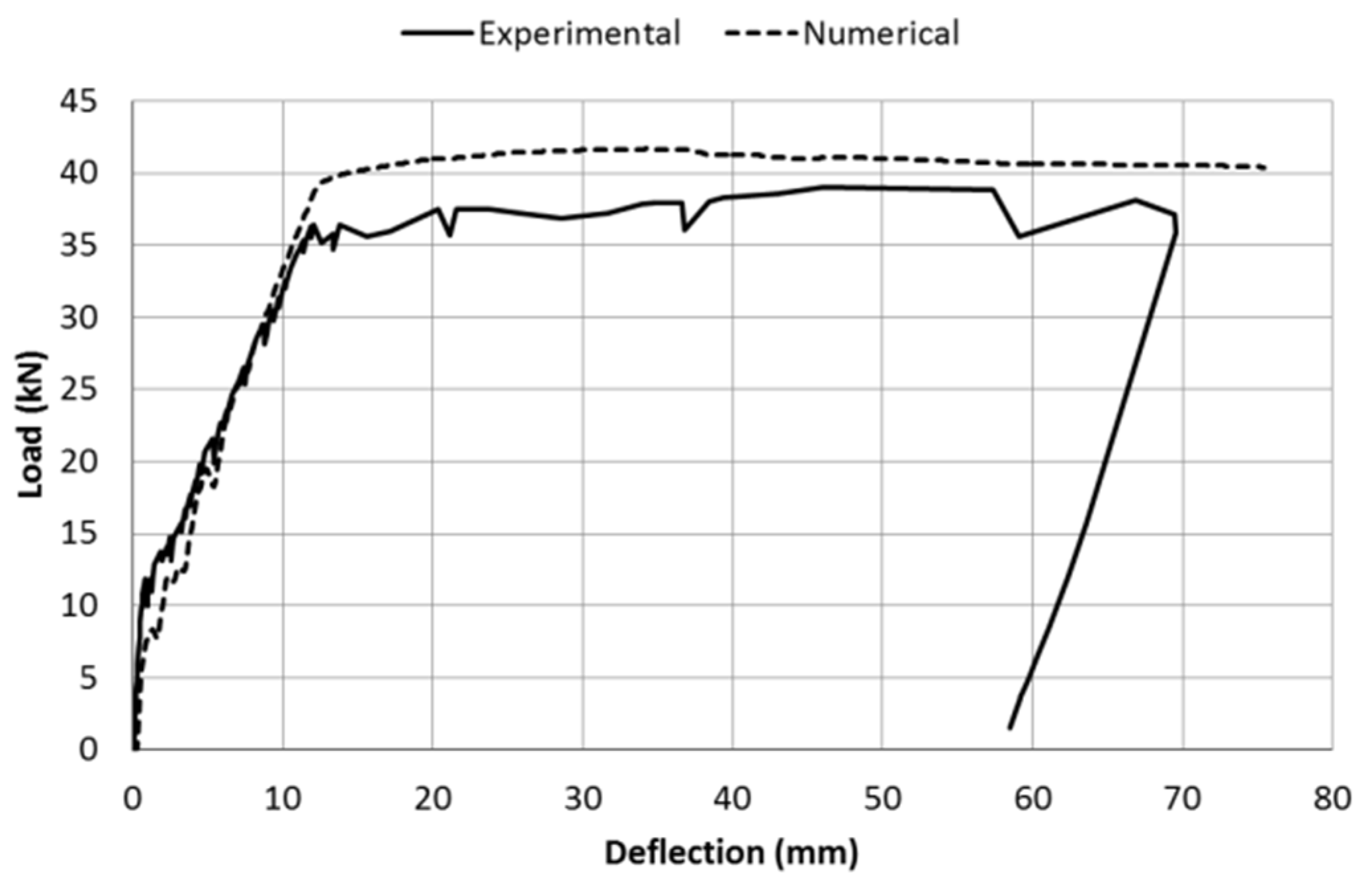
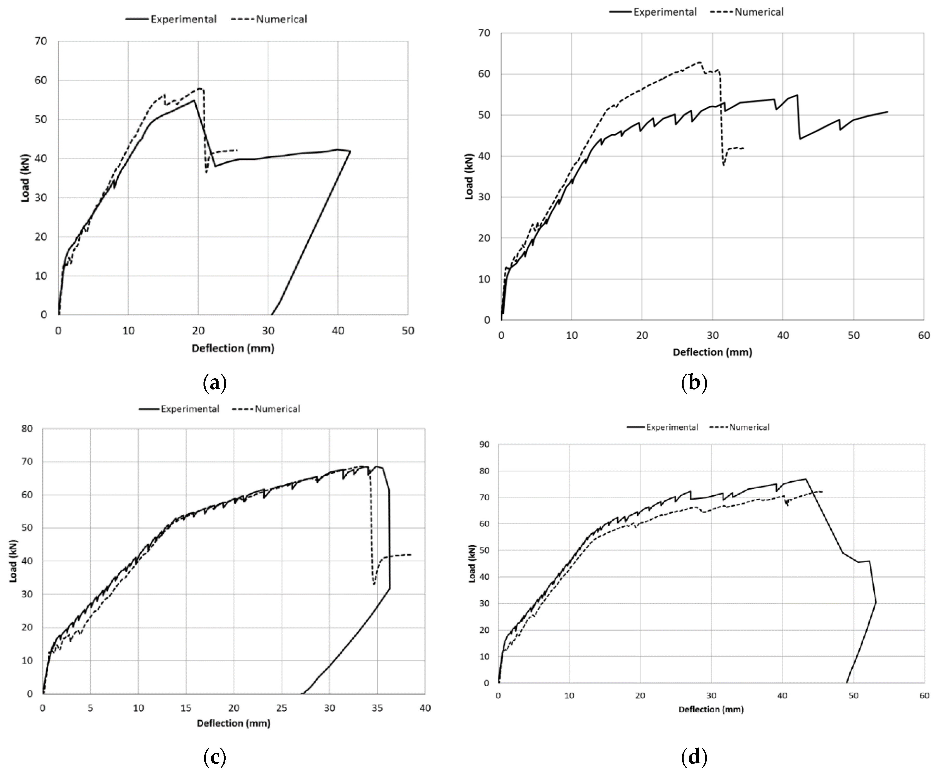
Figure 7 shows the numerical and experimental comparison of the load-midspan deflection curve for the unstrengthened beam CB. Same comparisons, for the strengthened beams, are given in Figure 8a–d.
Table 5 gives the numerical and experimental comparisons in terms of failure modes, load values at first crack (Fcr), tension steel yield (Fy), ultimate (Fu), and the material strains at failure in the midspan section (εc is the compression concrete strain, εs is the tensile steel strain, εf is the tensile UHTSS strain). Furthermore, in order to check the accuracy of the FE model, the absolute percentage errors on the ultimate load were calculated. The values range from 0.04% to 13.95% and are also given in Table 5.
In general, the numerical load-midspan deflection curves fit very well with the experimental ones (Figure 7 and Figure 8) and the comparisons between numerical and experimental results (Table 5) are satisfactory, except for the beam G1-U. With reference to this beam, although both the numerical and experimental failure modes were U-wrap end debonding, the absolute percentage error is high (13.95%). This is probably due to the value of the numerical yielding strength of the internal tensile steel (assumed as the average of the experimental tensile tests, 604.2 MPa) being higher than the actual experimental value. As a result, the numerical yielding load (52.39 kN) is considerably higher that the corresponding experimental value (44.16 kN). Consequently, the numerical ultimate load (62.59 kN) is also greater compared to the experimental one (54.93 kN).
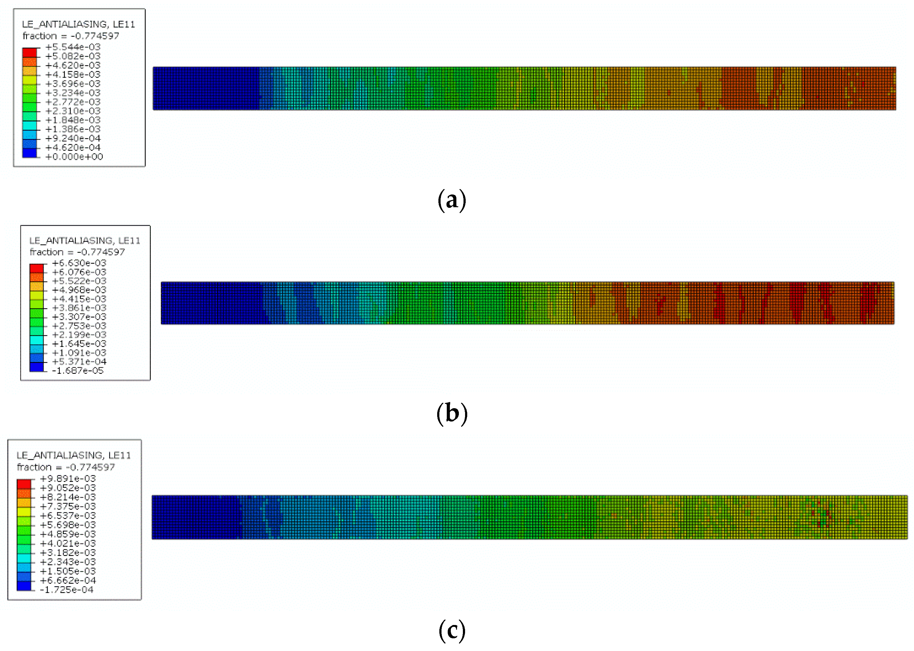
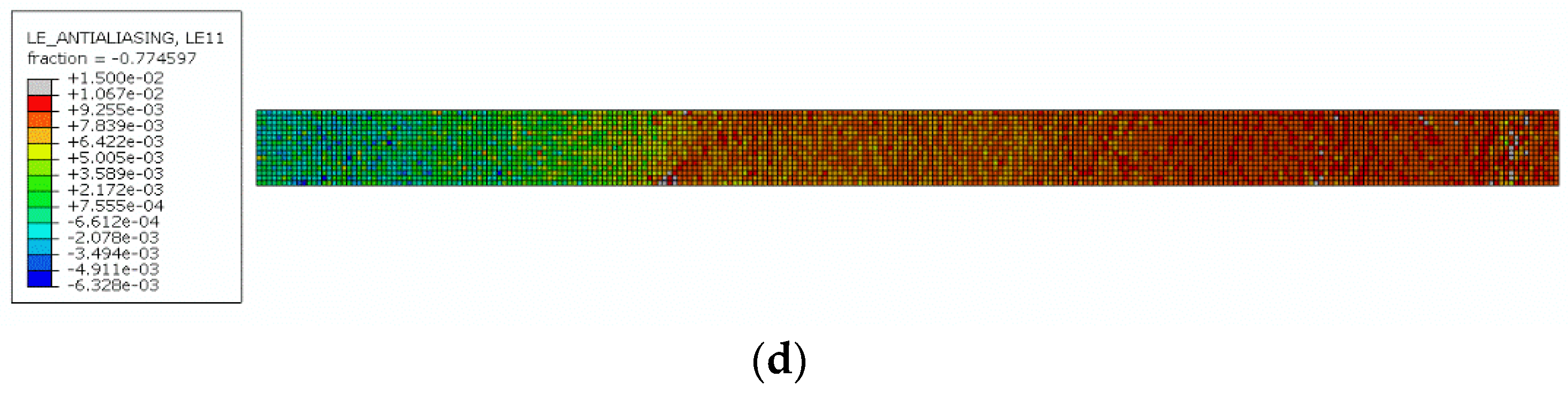
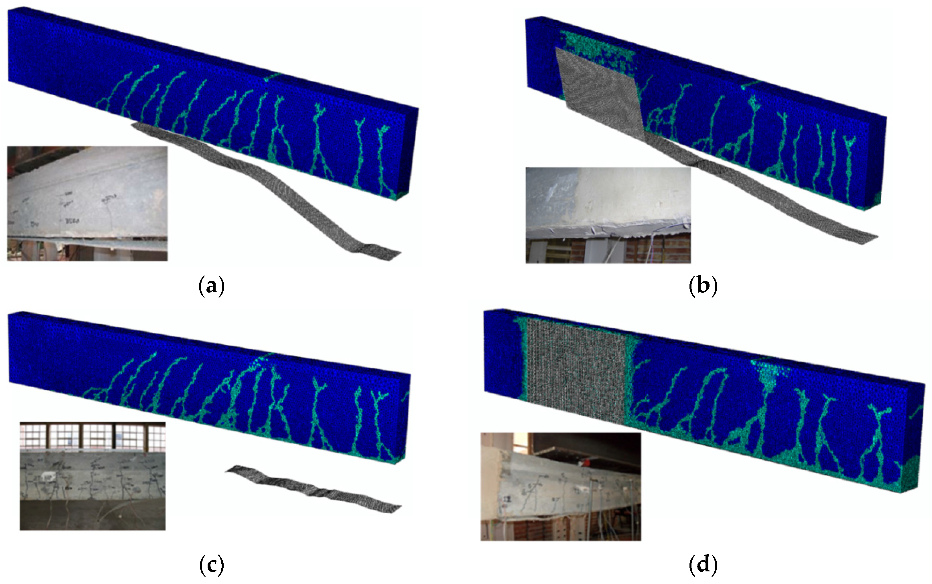
Figure 9a–d show the numerical normal strains along the UHTSS strip, it was modeled as a shell with brittle elastic isotropic material, at failure. The numerical and experimental comparisons of the failure mode for the four strengthened beams are shown in Figure 10a–d. In these Figures the numerical cracking patterns at failure are also given.
5. Conclusions
The work developed shows that the proposed 3D FE model, with an appropriate concrete-external reinforcement bond-slip law, is able to predict the structural behavior of the RC beams strengthened by means of SRG and SRP systems, with or without U-wrap end anchorages. In fact, the comparisons between the experimental and numerical results are satisfactory. On the basis of the results that were obtained some concluding remarks can be drawn:
- The SRG/SRP-concrete bond-slip laws calibrated and validated by Bencardino and Condello [23] provide a good prediction of the structural behavior of SRG/SRP strengthened RC beams with U-wrap end anchorages as well.
- Numerical failure modes are, in general, coherent with the experimental ones.
- The average percentage error on the ultimate load value is about 6.5% and it is 4.6% excluding the beam G1-U. This highlights the accuracy of the FE model.
- The explicit dynamic method, used for the nonlinear analysis, can efficiently overcome convergence difficulties due to strain softening. It can be a good alternative to various static solution methods to solve quasi-static structural problems which involve concrete cracking and debonding phenomena.
- Engineers and researchers can use the proposed FE model as a numerical tool to investigate the performance of similar beams without carrying out experimental tests.
Acknowledgments
Part of the analyses were developed within the activities of Rete dei Laboratori Universitari di Ingegneria Sismica (ReLUIS) for the research program funded by the Dipartimento di Protezione Civile (DPC), Progetto DPC/ReLUIS 2015—AQ DPC/ReLUIS 2014–2018.
Author Contributions
Francesco Bencardino designed and carried out the experimental tests. Antonio Condello performed the numerical analysis. Both the authors developed the topic, and discussed and analyzed the results.
Conflicts of Interest
The authors declare no conflict of interest.
References
- Bakis, C.E.; Bank, L.C.; Brown, V.L.; Cosenza, E.; Davalos, J.F.; Lesko, J.J.; Machida, A.; Rizkalla, S.H.; Triantafillou, T.C. Fiber-reinforced polymer composites for construction-state-of-the-art review. J. Compos. Constr. 2002, 6, 73–87. [Google Scholar] [CrossRef]
- Bencardino, F.; Colotti, V.; Spadea, G.; Swamy, R.N. Holistic design of RC beams and slabs strengthened with externally bonded FRP laminates. Cem. Concr. Compos. 2006, 28, 832–844. [Google Scholar] [CrossRef]
- Demakos, C.B.; Repapis, C.C.; Drivas, D. Investigation of structural response of reinforced concrete beams strengthened with anchored FRPs. Open Constr. Build. Technol. J. 2013, 7, 146–157. [Google Scholar] [CrossRef]
- Jumaat, M.Z.; Ashraful Alam, M.D. Experimental and numerical analysis of end anchored steel plate and CFRP laminate flexurally strengthened reinforced concrete (r.c.) beams. Int. J. Phys. Sci. 2010, 5, 132–144. [Google Scholar]
- Lu, X.Z.; Ye, L.P.; Teng, J.G.; Jiang, J.J. Meso-scale finite element model for FRP sheets/plates bonded to concrete. Eng. Struct. 2005, 27, 564–575. [Google Scholar] [CrossRef]
- Obaidat, Y.T.; Heyden, S.; Dahlblom, O. The Effect of CFRP and CFRP/Concrete Interface Models when modelling Retrofitted RC Beams with FEM. Compos. Struct. 2010, 92, 1391–1398. [Google Scholar] [CrossRef]
- Camata, G.; Spacone, E.; Zarnic, R. Experimental and nonlinear finite element studies of RC beams strengthened with FRP plates. Compos. B Eng. 2007, 38, 277–288. [Google Scholar] [CrossRef]
- Zhang, L.; Teng, J.G. Finite element prediction of interfacial stresses in structural members bonded with a thin plate. Eng. Struct. 2010, 32, 459–471. [Google Scholar] [CrossRef]
- Figeys, W.; Schueremans, L.; van Gemert, D.; Brosens, K. A new composite for external reinforcement: Steel cord reinforced polymer. Constr. Build. Mater. 2008, 22, 1929–1938. [Google Scholar] [CrossRef]
- Huang, X.; Birman, V.; Nanni, A.; Tunis, G. Properties and potential for application of steel reinforced polymer and steel reinforced grout composites. Compos. B Eng. 2004, 36, 73–82. [Google Scholar] [CrossRef]
- Abdelrahman, K.; El-Hacha, R. Behavior of large-scale concrete columns wrapped with CFRP and SFRP sheets. J. Compos. Constr. 2012, 16, 430–439. [Google Scholar] [CrossRef]
- Bencardino, F.; Condello, A. Structural behaviour of RC beams externally strengthened in flexure with SRG and SRP systems. Int. J. Struct. Eng. 2014, 5, 346–368. [Google Scholar] [CrossRef]
- Bencardino, F.; Ombres, L. Structural performance of RC beams strengthened by SRG and FRCM system. In Large Structures Infrastructures Environmentally Constrained and Urbanised Areas; ISBSE: Zurich, Switzerland, 2010; pp. 488–489. [Google Scholar]
- Barton, B.; Wobbe, E.; Dharani, L.R.; Silva, P.; Birman, V.; Nanni, A.; Alkhrdaji, T.; Thomas, J.; Tunis, G. Characterization of reinforced concrete beams strengthened by steel reinforced polymer and grout (SRP and SRG) composites. Mater. Sci. Eng. 2005, 412, 129–136. [Google Scholar] [CrossRef]
- Balsamo, A.; Nardone, F.; Iovinella, I.; Ceroni, F.; Pecce, M. Flexural strengthening of concrete beams with EB-FRP, SRP and SRCM: Experimental investigation. Compos. B Eng. 2013, 46, 91–101. [Google Scholar] [CrossRef]
- El-Hacha, R.; Mashrik, M.A. Effect of SFRP confinement on circular and square concrete columns. Eng. Struct. 2012, 36, 379–393. [Google Scholar] [CrossRef]
- Napoli, A.; Realfonzo, R. Compressive behavior of concrete confined by SRP wraps. Constr. Build. Mater. 2015. [Google Scholar] [CrossRef]
- Ombres, L. Flexural analysis of reinforced concrete beams strengthened with a cement based high strength composite material. Compos. Struct. 2011, 94, 143–155. [Google Scholar] [CrossRef]
- Pecce, M.; Ceroni, F.; Prota, A.; Manfredi, G. Response prediction of RC beams externally bonded with steel-reinforced polymers. J. Compos. Constr. 2006, 10, 195–203. [Google Scholar] [CrossRef]
- Thermou, G.E.; Katakalos, K.; Manos, G. Influence of the cross section shape on the behaviour of SRG-confined prismatic concrete specimens. Mater. Struct. 2016, 49, 869–887. [Google Scholar] [CrossRef]
- Thermou, G.E.; Katakalos, K.; Manos, G. Concrete confinement with steel-reinforced grout jackets. Mater. Struct. 2015, 48, 1355–1376. [Google Scholar] [CrossRef]
- Thermou, G.E.; Pantazopoulou, S.J. Metallic fabric jackets: An innovative method for seismic retrofitting of substandard RC prismatic members. Struct. Concr. 2007, 8, 35–46. [Google Scholar] [CrossRef]
- Bencardino, F.; Condello, A. SRG/SRP–concrete bond–slip laws for externally strengthened RC beams. Compos. Struct. 2015, 132, 804–815. [Google Scholar] [CrossRef]
- Bencardino, F.; Condello, A. Reliability and adaptability of the analytical models proposed for the FRP systems to the Steel Reinforced Polymer and Steel Reinforced Grout strengthening systems. Compos. B Eng. 2015, 76, 249–259. [Google Scholar] [CrossRef]
- Technical data sheets Kimia S.p.A. Unidirectional high-strength carbon steel fibre reinforcing mesh, Kimisteel 1500, ST2-0610; Ready-to-use fine granulometry mortar for SRG and SRP systems, Kimisteel LM, ST2-0610; Synthetic resin used to improve the chemical and physical properties of single-component mortars (SRG), Kimitech B2, ST9-0607; Bicomponent epoxy resin used to improve the chemical and physical properties of single-component mortars (SRP), Kimicover FIX, ST3-0503, 2009. Available online: http://www.kimia.it/en/prodotti/categorie-merceologiche/83 (accessed on 22 September 2009).
- Hibbitt, Karlsson and Sorensen, Inc. ABAQUS Finite Element Code (2011); Hibbitt, Karlsson & Sorensen: Pawtucket, RI, USA, 2011. [Google Scholar]
- Lee, J.; Fenves, G. Plastic-Damage Model for Cyclic Loading of Concrete Structures. J. Eng. Mech. 1998, 124, 892–900. [Google Scholar] [CrossRef]
- Lubliner, J.; Oliver, J.; Oller, S.; Oñate, E. A Plastic-Damage Model for Concrete. Int. J. Solids Struct. 1989, 25, 299–329. [Google Scholar] [CrossRef]
- European Committee for Standardization. Design of Concrete Structures—Part 1-1: General Rules and Rules for Buildings EN 1992-1-1; Eurocode 2; European Committee for Standardization: Brussels, Belgium, 2004. [Google Scholar]
- Hognestad, E. A Study of Combined Bending and Axial Load in Reinforced Concrete Members. In Bulletin Series No. 399, Engineering Experiment Station; University of Illinois: Champaign, IL, USA, 1951; Volume 49. [Google Scholar]
- Alfano, G.; Crisfield, M.A. Finite element interface models for the delamination analysis of laminated composites: Mechanical and computational issues. Int. J. Numer. Methods Eng. 2001, 50, 1701–1736. [Google Scholar] [CrossRef]
- Turon, A.; Davila, C.G.; Camanho, P.P.; Costa, J. An engineering solution for mesh size effects in the simulation of delamination using cohesive zone models. Eng. Fract. Mech. 2007, 74, 1665–1682. [Google Scholar] [CrossRef]
- Obaidat, Y.T.; Heyden, S.; Dahlblom, O. Evaluation of parameters of bond action between FRP and concrete. J. Compos. Constr. 2013, 17, 626–635. [Google Scholar] [CrossRef]
- Monti, M.; Renzelli, M.; Luciani, P. FRP adhesion in uncracked and cracked concrete zones. In Proceedings of the 6th International Symposium on FRP Reinforcement for Concrete Structures, Singapore, 8–10 July 2003.
- Lu, X.Z.; Teng, J.G.; Yea, L.P.; Jiang, J.J. Bond–slip models for FRP sheets/plates bonded to concrete. Eng. Struct. 2005, 27, 920–937. [Google Scholar] [CrossRef]
- Guide for the Design and Construction of Externally Bonded FRP Systems for Strengthening Existing Structures—Materials, RC and PC Structures, Masonry Structures; CNR-DT 200 R1/2013; Italian National Research Council: Rome, Italy, 2013.
- Chen, G.M.; Teng, J.G.; Chen, J.F.; Xiao, Q.G. Finite element modeling of debonding failures in FRP-strengthened RC beams: A dynamic approach. Comput. Struct. 2015, 158, 167–183. [Google Scholar] [CrossRef]
Figure 1.
Prototypes: (a) Geometry of the control beam (CB); (b) Internal steel reinforcement; (c) Beams G1, P1; (d) Beams G1-U, P1-U.
Figure 1.
Prototypes: (a) Geometry of the control beam (CB); (b) Internal steel reinforcement; (c) Beams G1, P1; (d) Beams G1-U, P1-U.

Figure 2.
Instrumentation: (a) Internal and external strain gauges position along the strengthened beams; (b) Position of the Linear Variable Displacement Transducers (LVDTs) on the front face of the beams; (c) Position of the LVDTs on the back face of the beams.
Figure 2.
Instrumentation: (a) Internal and external strain gauges position along the strengthened beams; (b) Position of the Linear Variable Displacement Transducers (LVDTs) on the front face of the beams; (c) Position of the LVDTs on the back face of the beams.

Figure 3.
Experimental test setup.

Figure 4.
Three-dimensional (3D) Finite Element (FE) mesh.

Figure 5.
Behavior of the concrete to uniaxial loading: (a) compression; (b) tension.

Figure 6.
Traction-separation response: (a) mode I; (b) modes II and III.

Figure 7.
Beam CB: Experimental/Numerical load-midspan deflection curve.

Figure 8.
Experimental/Numerical load-midspan deflection curve: (a) Beam G1; (b) Beam G1-U; (c) Beam P1; (d) Beam P1-U.
Figure 8.
Experimental/Numerical load-midspan deflection curve: (a) Beam G1; (b) Beam G1-U; (c) Beam P1; (d) Beam P1-U.

Figure 9.
Numerical UHTSS strains at failure: (a) Beam G1; (b) Beam G1-U; (c) Beam P1; (d) Beam P1-U.
Figure 9.
Numerical UHTSS strains at failure: (a) Beam G1; (b) Beam G1-U; (c) Beam P1; (d) Beam P1-U.


Figure 10.
Numerical/Experimental failure mode: (a) Beam G1; (b) Beam G1-U; (c) Beam P1; (d) Beam P1-U.
Figure 10.
Numerical/Experimental failure mode: (a) Beam G1; (b) Beam G1-U; (c) Beam P1; (d) Beam P1-U.


| Diameter of the Steel Bars | Yield Strength (MPa) | Tensile Strength (MPa) |
|---|---|---|
| Longitudinal 10 mm | 604.2 | 717.3 |
| Longitudinal 8 mm | 380.1 | 517.5 |
| Transversal 8 mm | 496.0 | 644.9 |
| Properties | Value |
|---|---|
| Total weight of fabric | 1528 g/m2 |
| Fiber direction (Warp–Steel) | 99% |
| Fiber direction (weft) | 1% |
| Diameter steel chord (plait/braid) | 1.07 mm |
| Equivalent dry fabric thickness (steel only) | 0.19 mm |
| Fiber tensile breaking stress | 2950 MPa |
| Unitary tensile strength (of the fabric) | 570 N/mm |
| Elastic tensile stress modulus (tangent modulus) | 206 GPa |
| Maximum tensile strain of the steel (εfu) | 2.3% |
Table 3.
Properties of the matrix used for the Steel Reinforced Grout (SRG) and Steel Reinforced Polymer (SRP) systems.
| Properties | SRG | SRP |
|---|---|---|
| Appearance | powder | |
| Color | grey | |
| Apparent volumetric mass of wet mortar | 1750 kg/m3 | 1700 kg/m3 |
| Consistency | 170% | 180% |
| Setting time (start), EN 196-3 | 72 min | 135 min |
| Setting time (end), EN 196-3 | 95 min | 186 min |
| Compression strength at 28 days, EN 1015-12 | >45 MPa | |
| Flexural strength at 28 days, EN 1015-11 | >8 MPa | |
| Concrete adhesion, EN 1542 | >2 MPa | |
| System | Bond-Slip Law | K0 (N/mm3) | τmax (N/mm2) | Gf (N/mm) |
|---|---|---|---|---|
| SRG | Lu et al. [35] | 76.92 | 3.91 | 0.32 |
| SRP | Proposed [23] | 76.92 | 5.00 | 0.70 |
Table 5.
Experimental/Numerical load and strain values. UHTSS refers to Ultra High Tensile Steel Strength.
| Beam | Value | Failure Mode | Load (kN) | Ultimate Strain (‰) | Err (%) | ||||
|---|---|---|---|---|---|---|---|---|---|
| Fcr | Fy | Fu | εc | εs | εf | ||||
| CB | Exp. | Concrete crushing | 9.89 | 35.30 | 38.98 | 3.53 | 25.29 | - | 6.90 |
| FEA | Concrete crushing | 11.01 | 39.06 | 41.67 | 3.50 | 21.76 | |||
| G1 | Exp. | End debonding | 13.71 | 48.07 | 54.93 | 2.17 | 3.04 | 4.95 | 5.39 |
| FEA | Intermediate debonding | 12.68 | 50.74 | 57.89 | 1.61 | 2.87 | 5.54 | ||
| G1-U | Exp. | U-wrap debonding | 11.92 | 44.16 | 54.93 | 2.83 | 3.23 | 7.36 | 13.95 |
| FEA | U-wrap debonding | 12.85 | 52.39 | 62.59 | 1.92 | 2.98 | 6.63 | ||
| P1 | Exp. | Intermediate debonding | 12.80 | 51.04 | 68.64 | 2.76 | 21.62 | 10.42 | 0.04 |
| FEA | Intermediate debonding | 12.63 | 50.89 | 68.67 | 2.37 | 6.35 | 9.89 | ||
| P1-U | Exp. | UHTSS rupture | 14.65 | 55.93 | 76.88 | 3.07 | 23.75 | 11.48 | 6.13 |
| FEA | UHTSS rupture | 12.86 | 52.74 | 72.17 | 2.72 | 7.02 | 10.67 | ||
© 2016 by the authors; licensee MDPI, Basel, Switzerland. This article is an open access article distributed under the terms and conditions of the Creative Commons Attribution (CC-BY) license (http://creativecommons.org/licenses/by/4.0/).
Share and Cite
MDPI and ACS Style
Bencardino, F.; Condello, A. 3D FE Analysis of RC Beams Externally Strengthened with SRG/SRP Systems. Fibers 2016, 4, 19. https://doi.org/10.3390/fib4020019
AMA Style
Bencardino F, Condello A. 3D FE Analysis of RC Beams Externally Strengthened with SRG/SRP Systems. Fibers. 2016; 4(2):19. https://doi.org/10.3390/fib4020019
Chicago/Turabian StyleBencardino, Francesco, and Antonio Condello. 2016. "3D FE Analysis of RC Beams Externally Strengthened with SRG/SRP Systems" Fibers 4, no. 2: 19. https://doi.org/10.3390/fib4020019
Note that from the first issue of 2016, this journal uses article numbers instead of page numbers. See further details here.