
Effect of Polymer Concentration, Rotational Speed, and Solvent Mixture on Fiber Formation Using Forcespinning®

 ,
,
Abstract
:1. Introduction
2. Materials and Methods
2.1. Materials
2.2. PCL Solution Preparation
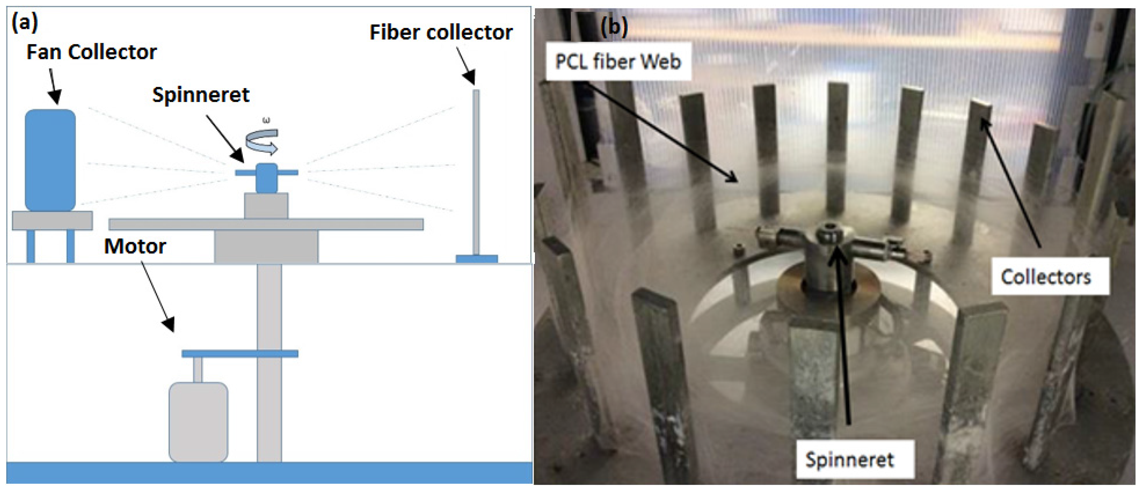
2.3. Forcespinning® of PCL Fibers
2.4. Fiber Characterization
2.4.1. Scanning Electron Microscopy
2.4.2. X-Ray Diffraction
2.4.3. Differential Scanning Calorimetry (DSC)
3. Results and Discussion
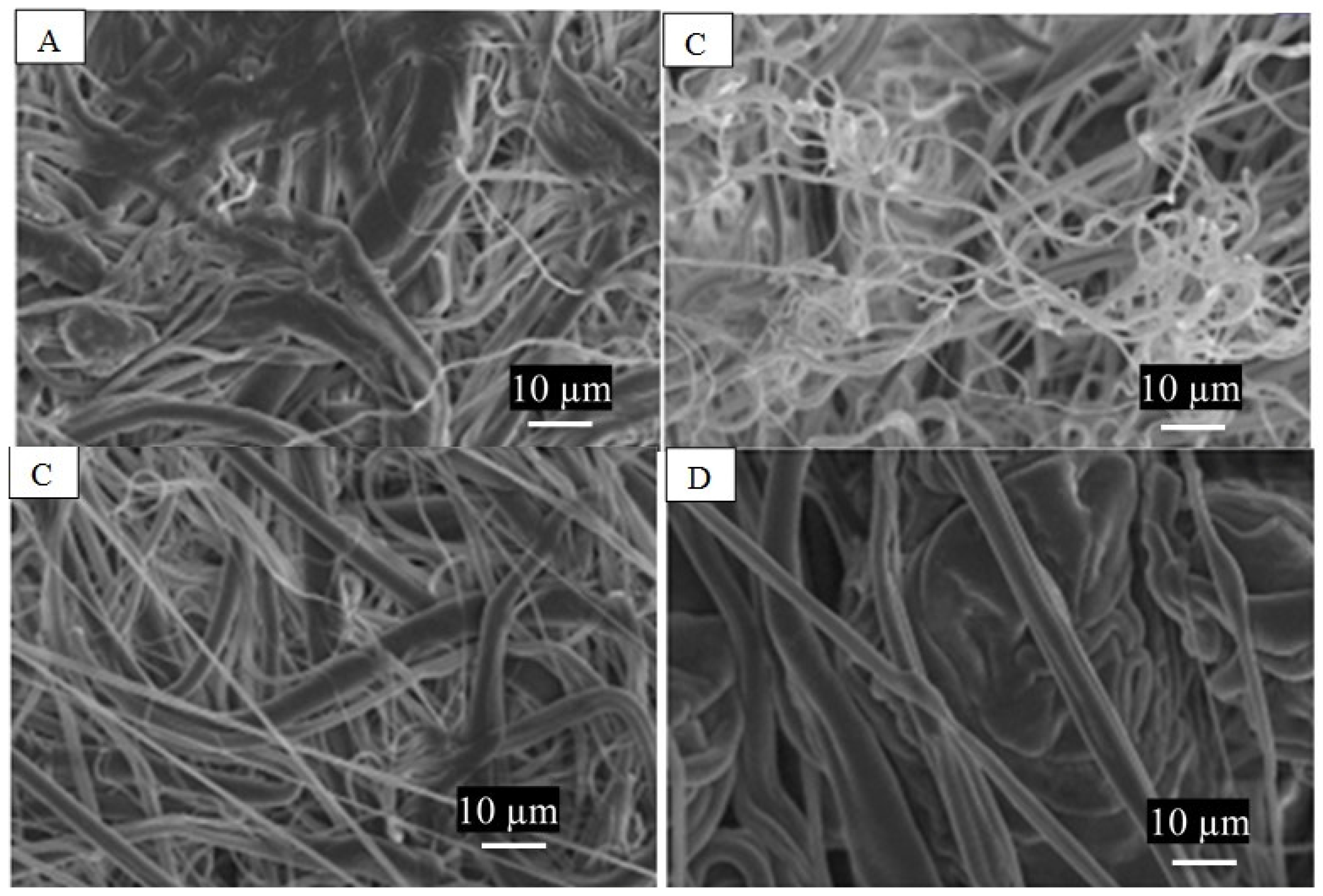
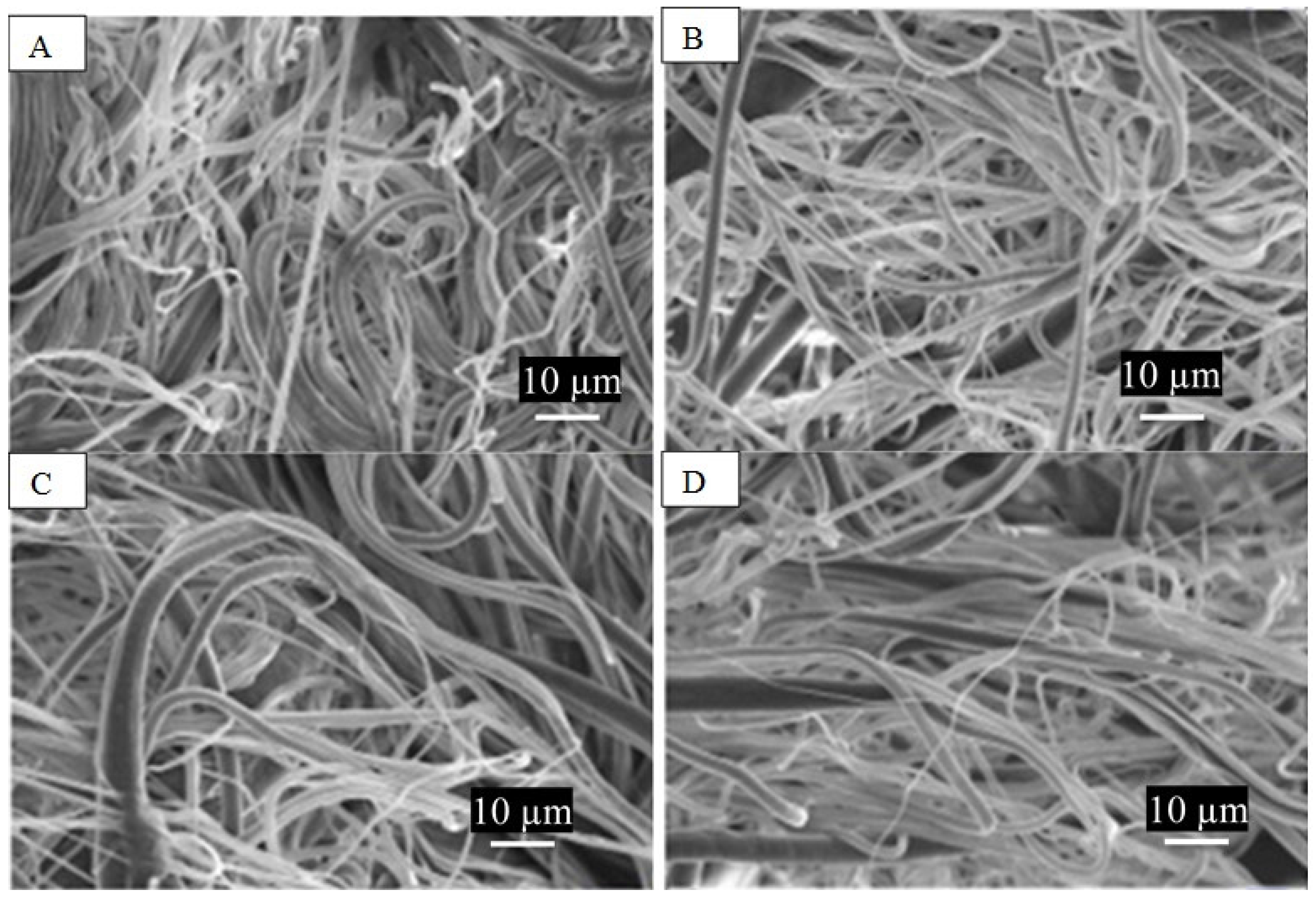
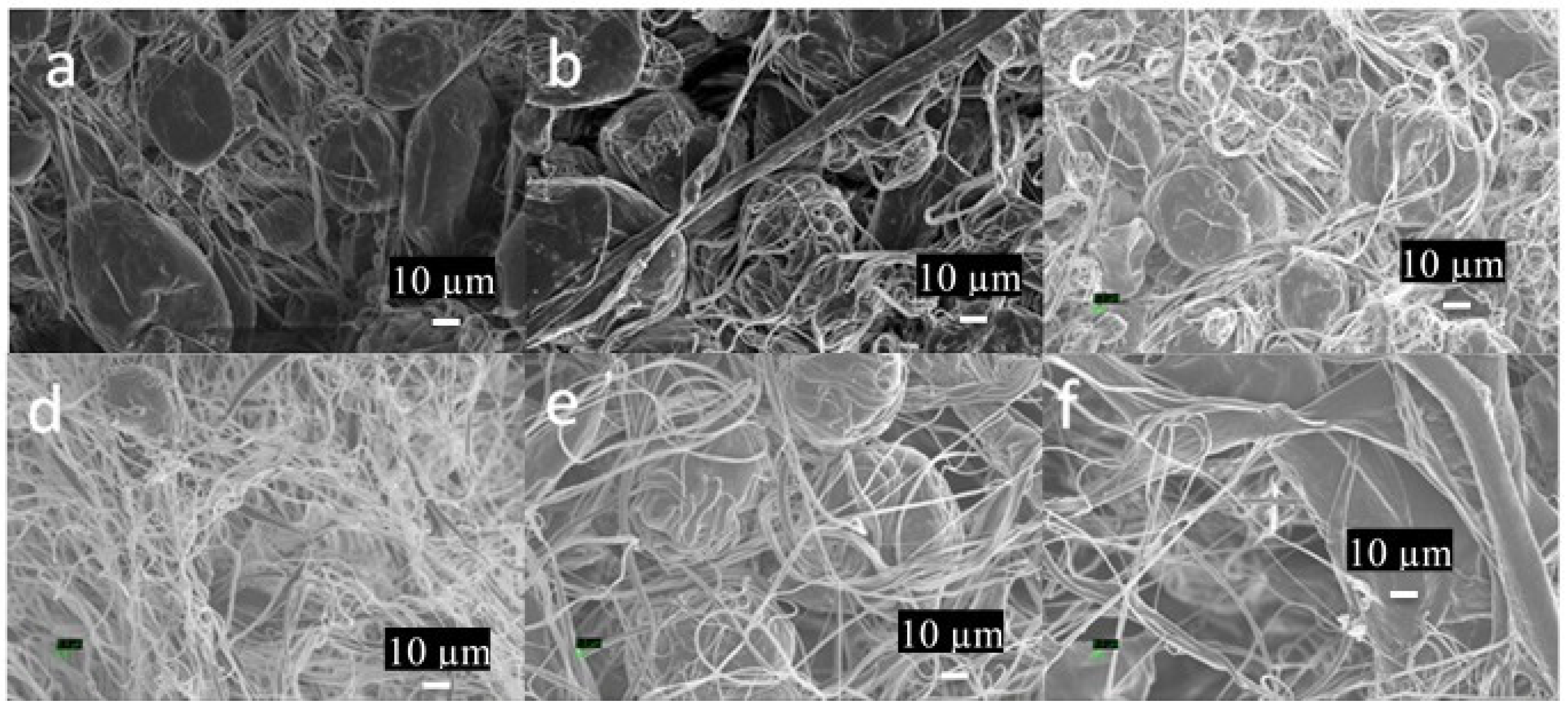
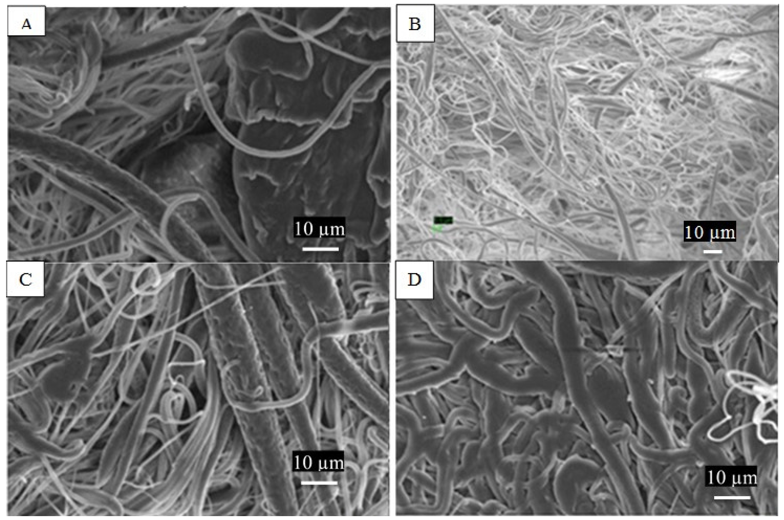
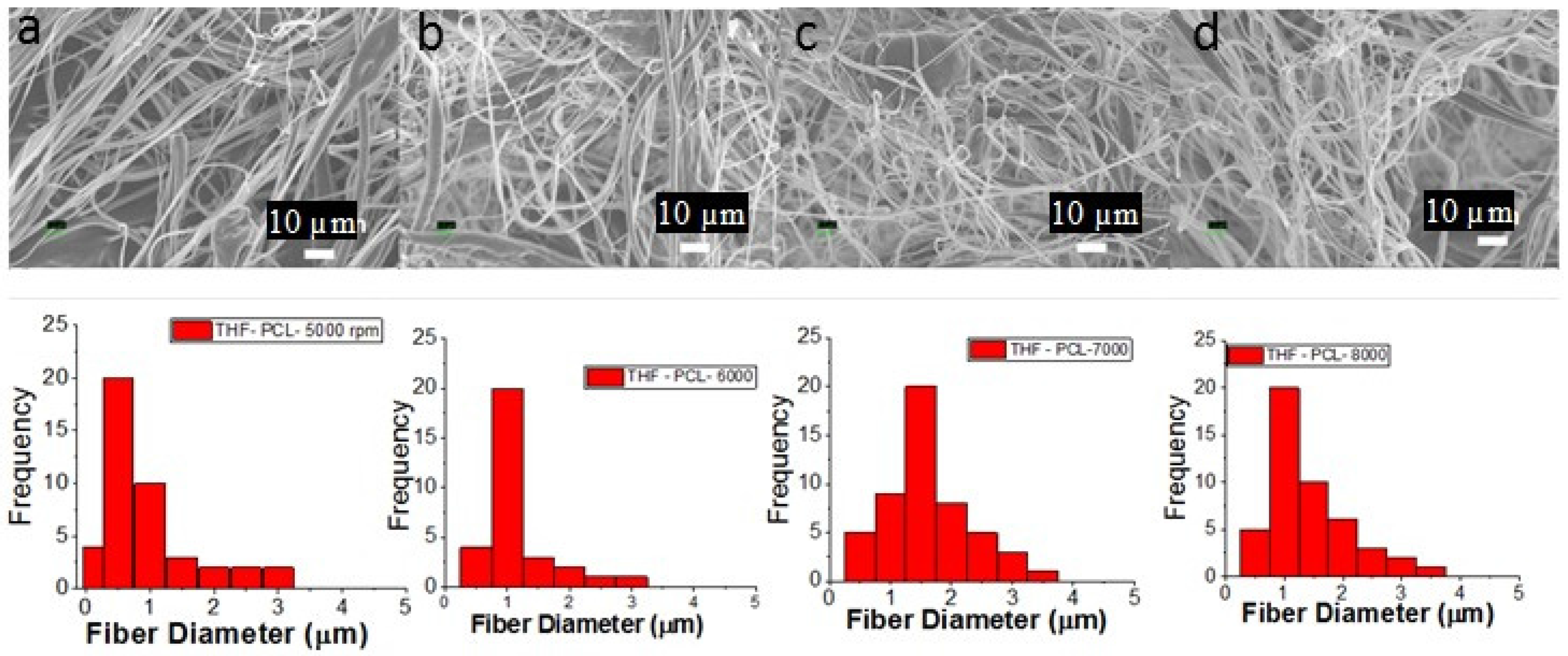
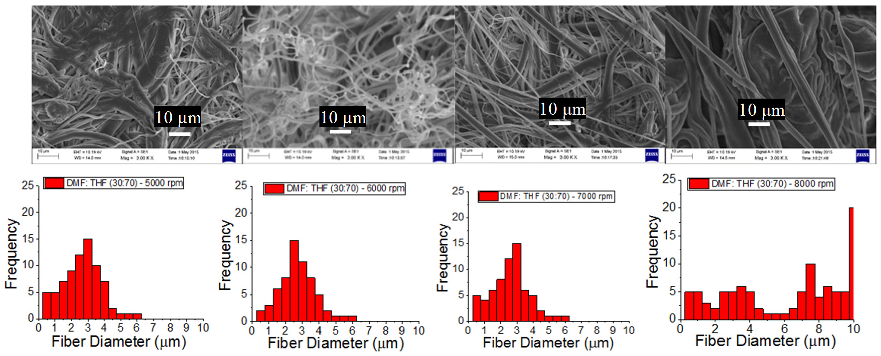
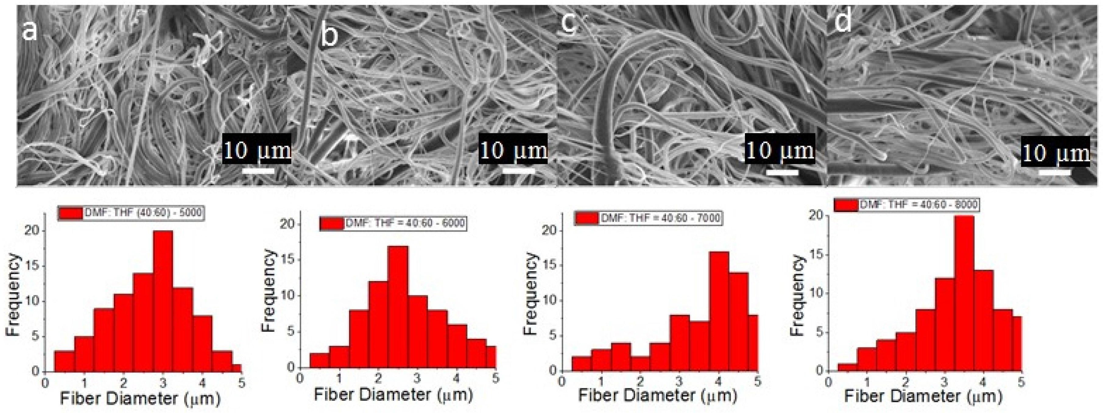
3.1. PCL Fiber Surface Characterization: SEM Analysis
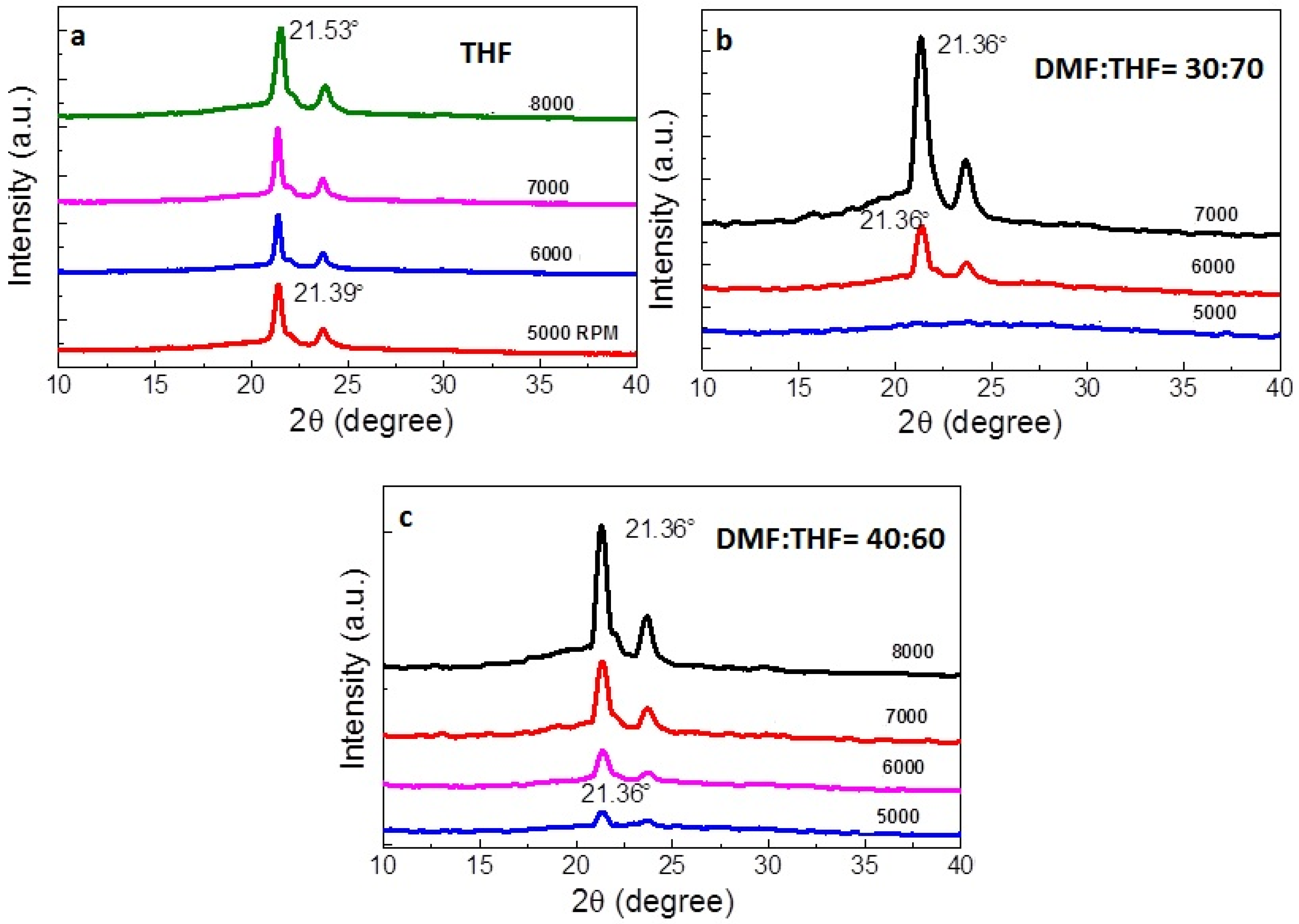
3.2. XRD Analysis
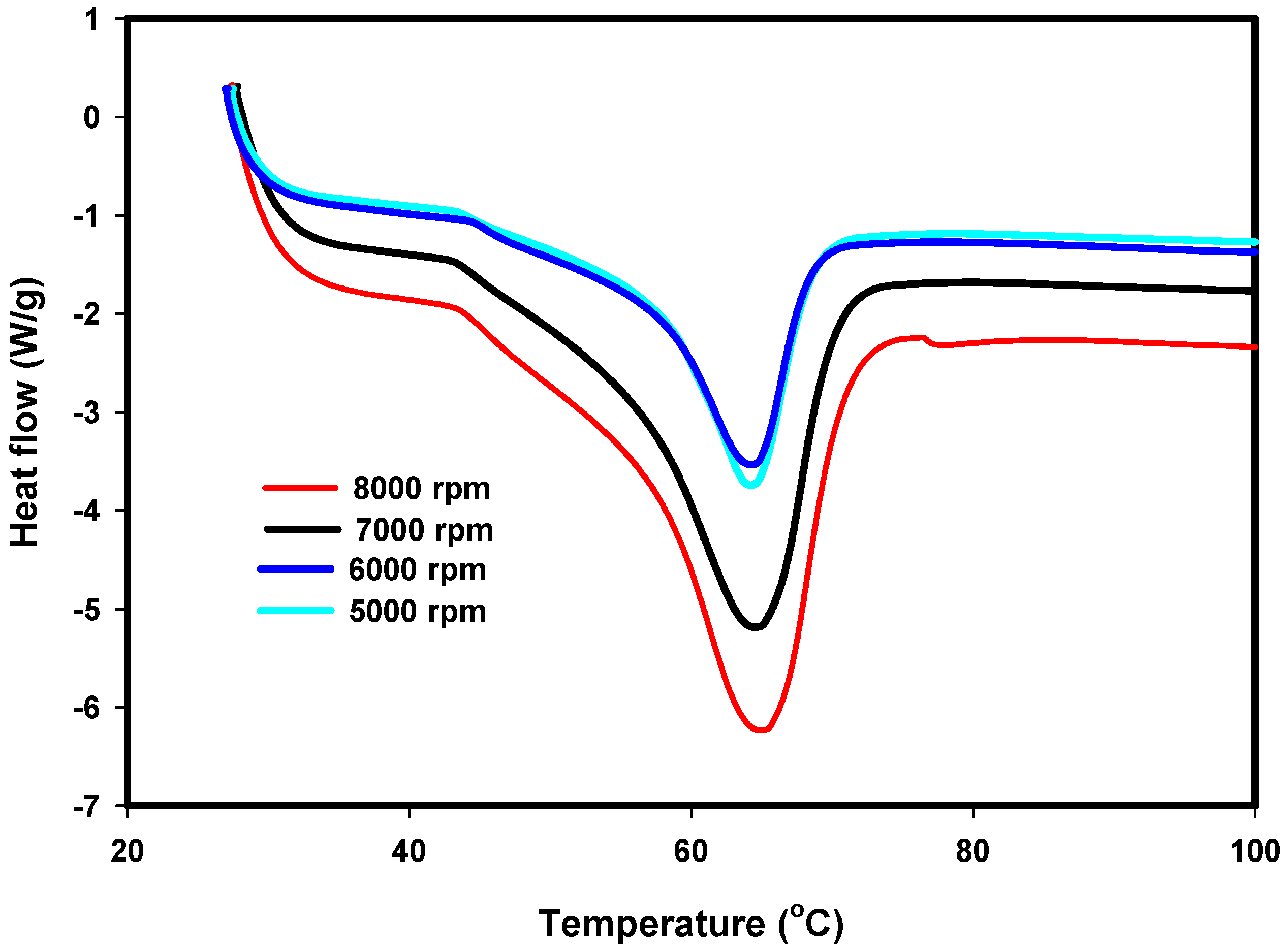
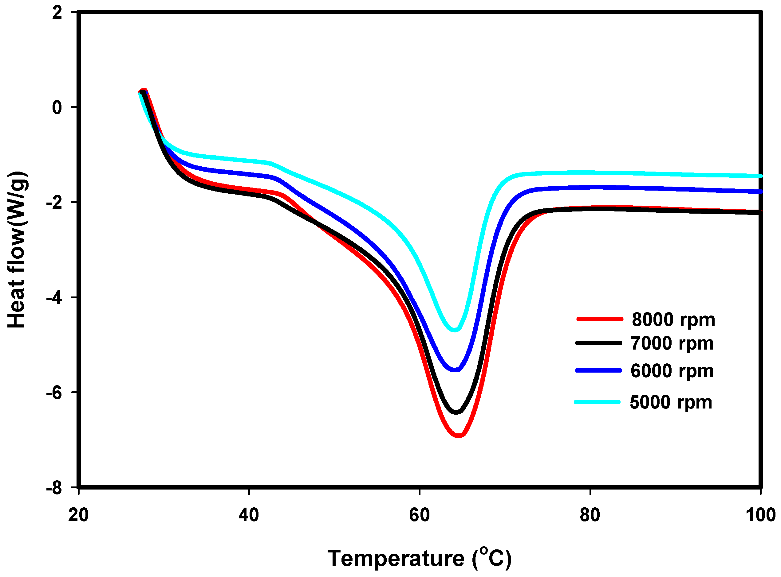
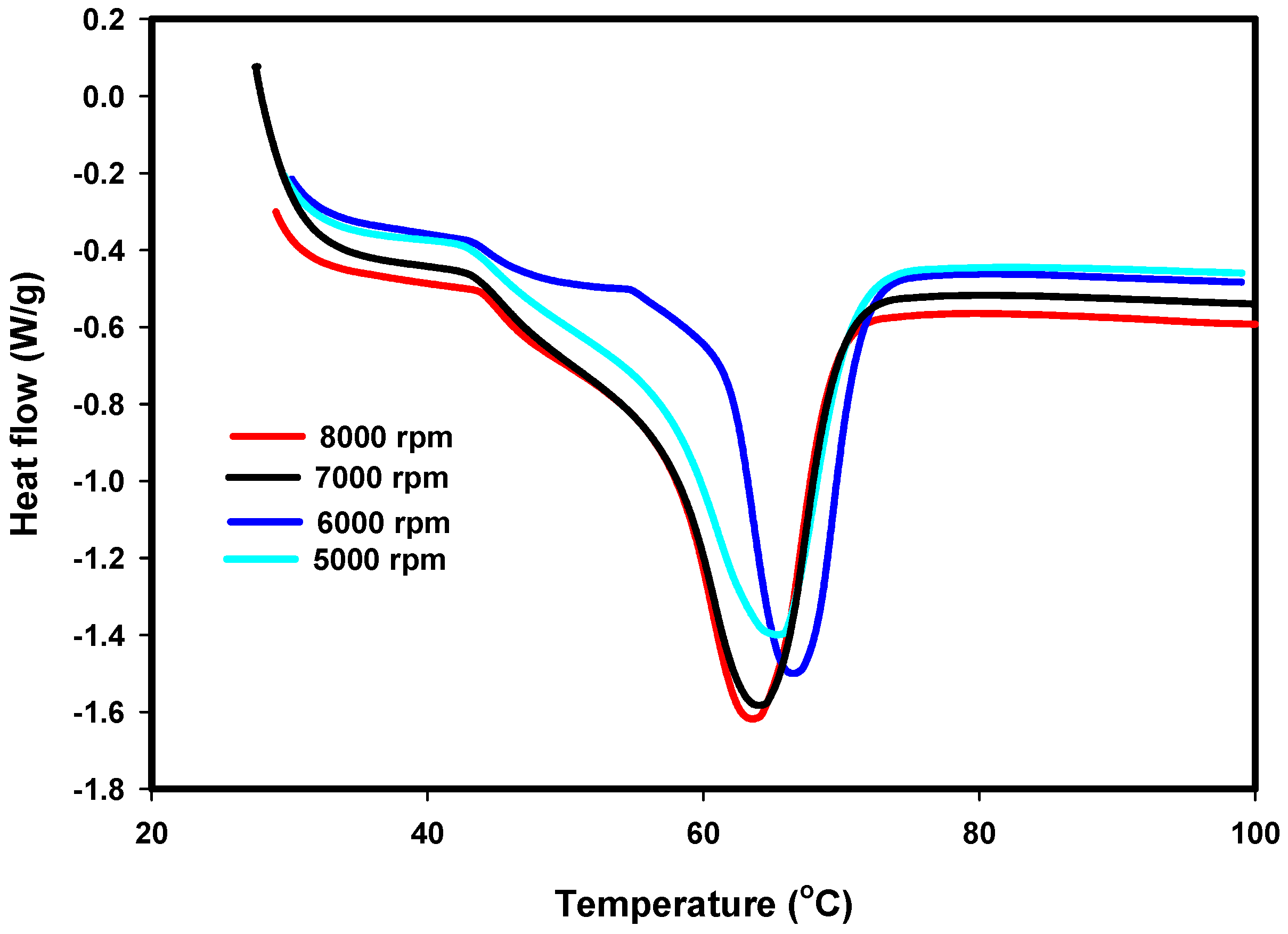
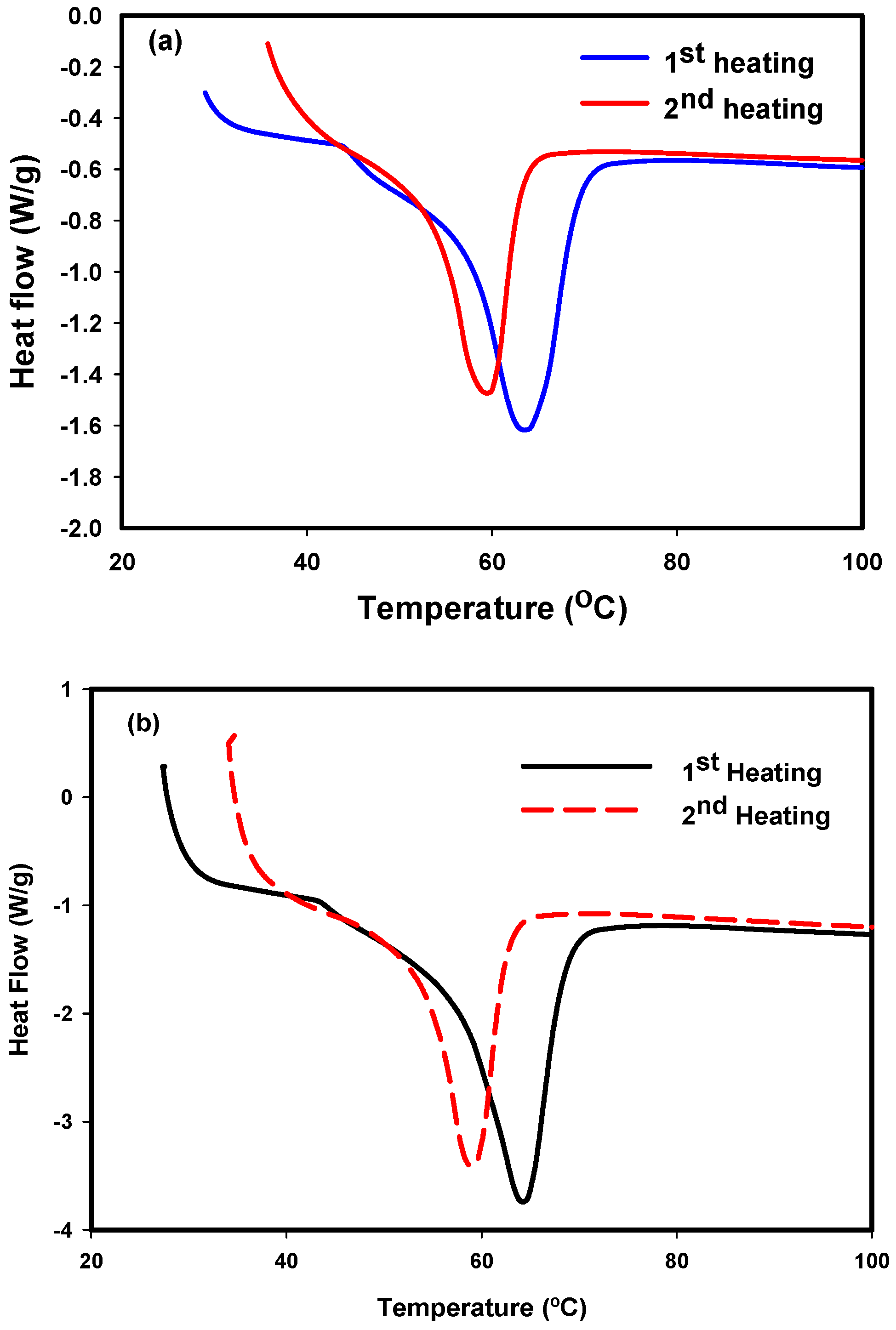
3.3. DSC Results
4. Conclusions
Supplementary Materials
Acknowledgments
Author Contributions
Conflicts of Interest
References
- Mohammed, L.; Ansari, M.N.M.; Pua, G.; Jawaid, M.; Islam, M.S. A review on natural fiber reinforced polymer composite and its applications. Int. J. Polym. Sci. 2015, 2015, 243947:1–243947:15. [Google Scholar] [CrossRef]
- Xu, X.; Jayaraman, K.; Morin, C.; Pecqueux, N. Life cycle assessment of wood-fibre-reinforced polypropylene composites. J. Mater. Process. Technol. 2008, 198, 168–177. [Google Scholar] [CrossRef]
- Zhou, L.; Zhao, G.; Feng, Y.; Yin, J.; Jiang, W. Toughening polylactide with polyether-block-amide and thermoplastic starch acetate: Influence of starch esterification degree. Carbohydr. Polym. 2015, 127, 79–85. [Google Scholar] [CrossRef] [PubMed]
- Tallawi, M.; Rosellini, E.; Barbani, N.; Cascone, M.G.; Rai, R.; Saint-Pierre, G.; Boccaccini, A.R. Strategies for the chemical and biological functionalization of scaffolds for cardiac tissue engineering: A review. J. R. Soc. Interface 2015, 12. [Google Scholar] [CrossRef] [PubMed]
- Becker, J.; Lu, L.; Runge, M.B.; Zeng, H.; Yaszemski, M.J.; Dadsetan, M. Nanocomposite bone scaffolds based on biodegradable polymers and hydroxyapatite. J. Biomed. Mater. Res. Part A 2015, 103, 2549–2557. [Google Scholar] [CrossRef] [PubMed]
- Cho, D.I.D.; Yoo, H.J. Microfabrication methods for biodegradable polymeric carriers for drug delivery system applications: A review. J. Microelectromech. Syst. 2015, 24, 10–18. [Google Scholar] [CrossRef]
- Colwell, J.M.; Wentrup-Byrne, E.; George, G.A.; Schue, F. A pragmatic calcium-based initiator for the synthesis of polycaprolactone copolymers. Polym. Int. 2015, 64, 654–660. [Google Scholar] [CrossRef]
- Woodruff, M.A.; Hutmacher, D.W. The return of a forgotten polymer—Polycaprolactone in the 21st century. Progr. Polym. Sci. 2010, 35, 1217–1256. [Google Scholar] [CrossRef] [Green Version]
- Yazdimamaghani, M.; Razavi, M.; Vashaee, D.; Pothineni, V.R.; Rajadas, J.; Tayebi, L. Significant degradability enhancement in multilayer coating of polycaprolactone-bioactive glass/gelatin-bioactive glass on magnesium scaffold for tissue engineering applications. Appl. Surf. Sci. 2015, 338, 137–145. [Google Scholar] [CrossRef]
- Makhijani, K.; Kumar, R.; Sharma, S.K. Biodegradability of blended polymers: A comparison of various properties. Crit. Rev. Environ. Sci. Technol. 2015, 45, 1801–1825. [Google Scholar] [CrossRef]
- Belkhir, K.; Shen, H.; Chen, J.; Jegat, C.; Taha, M. Synthesis of multi-thiol functionalized polylactic acid, polyhydroxybutyrate and polycaprolactone. Eur. Polym. J. 2015, 66, 290–300. [Google Scholar] [CrossRef]
- Oh, H.-K.; Lee, H.S.; Lee, J.H.; Oh, S.H.; Lim, J.-Y.; Ahn, S.; Hwang, J.-Y.; Kang, S.-B. Functional and histological evidence for the targeted therapy using biocompatible polycaprolactone beads and autologous myoblasts in a dog model of fecal incontinence. Dis. Colon Rectum 2015, 58, 517–525. [Google Scholar] [CrossRef] [PubMed]
- Li, D.; Xia, Y.N. Electrospinning of nanofibers: Reinventing the wheel? Adv. Mater. 2004, 16, 1151–1170. [Google Scholar] [CrossRef]
- Hassan, M.A.; Yeom, B.Y.; Wilkie, A.; Pourdeyhimi, B.; Khan, S.A. Fabrication of nanofiber meltblown membranes and their filtration properties. J. Membr. Sci. 2013, 427, 336–344. [Google Scholar] [CrossRef]
- Agubra, V.A.; De la Garza, D.; Gallegos, L.; Alcoutlabi, M. Forcespinning of polyacrylonitrile for mass production of lithium-ion battery separators. J. Appl. Polym. Sci. 2016, 133. [Google Scholar] [CrossRef]
- Smoukov, S.K.; Tian, T.; Vitchuli, N.; Gangwal, S.; Geisen, P.; Wright, M.; Shim, E.; Marquez, M.; Fowler, J.; Velev, O.D. Scalable liquid shear-driven fabrication of polymer nanofibers. Adv. Mater. 2015, 27, 2642–2647. [Google Scholar] [CrossRef] [PubMed]
- Tokarev, A.; Asheghali, D.; Ian, M.; Griffiths, I.M.; Trotsenko, O.; Gruzd, A.; Lin, X.; Stone, H.A.; Minko, S. Touch- and brush-spinning of nanofibers. Adv. Mater. 2015, 27, 6526–6532. [Google Scholar] [CrossRef] [PubMed]
- Tokarev, A.; Trotsenko, O.; Griffiths, I.M.; Stone, H.A.; Minko, S. Magnetospinning of nano- and microfibers. Adv. Mater. 2015, 27, 3560–3565. [Google Scholar] [CrossRef] [PubMed]
- Tokarev, A.T.; Asheghali, D.; Griffiths, I.M.; Stone, H.A.; Minko, S. Reactive magnetospinning of nano- and microfibers. In Angewandte Chemie (International ed. in English); WILEY-V C H VERLAG GMB: Weinheim, Germany, 2015; Volume 54, pp. 13613–13616. [Google Scholar]
- McEachin, Z.; Lozano, K. Production and characterization of polycaprolactone nanofibers via forcespinning (TM) technology. J. Appl. Polym. Sci. 2012, 126, 473–479. [Google Scholar] [CrossRef]
- He, M.; Xue, J.; Geng, H.; Gu, H.; Chen, D.; Shi, R.; Zhang, L. Fibrous guided tissue regeneration membrane loaded with anti-inflammatory agent prepared by coaxial electrospinning for the purpose of controlled release. Appl. Surf. Sci. 2015, 335, 121–129. [Google Scholar] [CrossRef]
- Zhang, Q.; Lv, S.; Lu, J.; Jiang, S.; Lin, L. Characterization of polycaprolactone/collagen fibrous scaffolds by electrospinning and their bioactivity. Int. J. Biol. Macromol. 2015, 76, 94–101. [Google Scholar] [CrossRef] [PubMed]
- Doustgani, A. Effect of electrospinning process parameters of polycaprolactone and nanohydroxyapatite nanocomposite nanofibers. Text Res. J. 2015, 85, 1445–1454. [Google Scholar] [CrossRef]
- Weng, B.C.; Xu, F.H.; Garza, G.; Alcoutlabi, M.; Salinas, A.; Lozano, K. The production of carbon nanotube reinforced poly(vinyl) butyral nanofibers by the forcespinning (R) method. Polym. Eng. Sci. 2015, 55, 81–87. [Google Scholar] [CrossRef]
- Sarkar, K.; Gomez, C.; Zambrano, S.; Ramirez, M.; de Hoyos, E.; Vasquez, H.; Lozano, K. Electrospinning to forcespinning™. Mater. Today 2010, 13, 12–14. [Google Scholar] [CrossRef]
- Weng, B.C.; Xu, F.H.; Alcoutlabi, M.; Mao, Y.B.; Lozano, K. Fibrous cellulose membrane mass produced via forcespinning® for lithium-ion battery separators. Cellulose 2015, 22, 1311–1320. [Google Scholar] [CrossRef]
- Hooper, J.P. Centrifugal Spinneret. US 1500931 A, 8 July 1924. [Google Scholar]
- Weitz, R.T.; Harnau, L.; Rauschenbach, S.; Burghard, M.; Kern, K. Polymer nanofibers via nozzle-free centrifugal spinning. Nano Lett. 2008, 8, 1187–1191. [Google Scholar] [CrossRef] [PubMed]
- Fong, H.; Chun, I.; Reneker, D.H. Beaded nanofibers formed during electrospinning. Polymer 1999, 40, 4585–4592. [Google Scholar] [CrossRef]
- Golecki, H.M.; Yuan, H.Y.; Glavin, C.; Potter, B.; Badrossamay, M.R.; Goss, J.A.; Phillips, M.D.; Parker, K.K. Effect of solvent evaporation on fiber morphology in rotary jet spinning. Langmuir 2014, 30, 13369–13374. [Google Scholar] [CrossRef] [PubMed]
- Ruder, W.C.; Pratt, E.D.; Bakhru, S.; Sitti, M.; Zappe, S.; Cheng, C.M.; Antaki, J.F.; LeDuc, P.R. Three-dimensional microfiber devices that mimic physiological environments to probe cell mechanics and signaling. Lab Chip 2012, 12, 1775–1779. [Google Scholar] [CrossRef] [PubMed]
- Ali Akbari Ghavimi, S.; Ebrahimzadeh, M.H.; Solati-Hashjin, M.; Abu Osman, N.A. Polycaprolactone/starch composite: Fabrication, structure, properties, and applications. J. Biomed. Mater. Res. Part A 2015, 103, 2482–2498. [Google Scholar] [CrossRef] [PubMed]
- Gonen, S.O.; Taygun, M.E.; Kucukbayrak, S. Effects of electrospinning parameters on gelatin/poly(epsilon-caprolactone) nanofiber diameter. Chem. Eng. Technol. 2015, 38, 844–850. [Google Scholar] [CrossRef]
- Mo, G.-Z.; Wu, Y.-C.; Hao, Z.-F.; Luo, Q.-F.; Liang, X.-Y.; Guan, L.-T.; Wang, Z.-Y. Synthesis and characterization of a novel drug-loaded polymer, poly(lactic acid-co-aminomethyl benzimidazole). Des. Monomers Polym. 2015, 18, 536–544. [Google Scholar] [CrossRef]
- Wei, K.; Kim, H.K.; Kimura, N.; Suzuki, H.; Satou, H.; Lee, K.H.; Park, Y.H.; Kim, I.S. Effects of organic solvent and solution temperature on electrospun polyvinylidene fluoride nanofibers. J. Nanosci. Nanotechnol. 2013, 13, 2708–2713. [Google Scholar] [CrossRef] [PubMed]
- Kanani, A.G.; Bahrami, S.H. Effect of changing solvents on poly(epsilon-caprolactone) nanofibrous webs morphology. J. Nanomater. 2011, 2011, 724153:1–724153:10. [Google Scholar]
- Yu, Y.S.; White, J.L. Comparison of structure development in quiescent crystallization, die extrusion and melt spinning of isotactic polypropylene and its compounds containing fillers and nucleating agents. Polym. Eng. Sci. 2001, 41, 1292–1298. [Google Scholar] [CrossRef]
- Wang, C.; Jheng, J.H.; Chiu, F.C. Electrospun nylon-4,6 nanofibers: Solution rheology and brill transition. Colloid Polym. Sci. 2013, 291, 2337–2344. [Google Scholar] [CrossRef]


| DMF:THF | Spinneret Speed | First Heating | Second Heating | Cooling | ||||
|---|---|---|---|---|---|---|---|---|
| ΔHm (J/g) | ΔTm (°C) | ΔHm (J/g) | ΔTm (°C) | ΔHc (J/g) | ΔTc (°C) | Crystallinity | ||
| PCL (Bulk) | – | 60.4 | 65.9 | 48.6 | 58.4 | 30.1 | 31.7 | 0.22 |
| 00:100 | 5000 | 56.9 | 63.3 | 49.2 | 58.4 | 43.9 | 34.5 | 0.1 |
| 6000 | 52.5 | 66.2 | 42.8 | 59.9 | 35.6 | 34.4 | 0.12 | |
| 7000 | 51.9 | 62.5 | 45 | 58.1 | 43.3 | 36 | 0.1 | |
| 8000 | 62.4 | 63.3 | 45.5 | 61.5 | 45.5 | 35.8 | 0.12 | |
| 30:70 | 5000 | 66.9 | 64.3 | 56 | 59.4 | 50.9 | 35.4 | 0.12 |
| 6000 | 73.3 | 64.2 | 52.6 | 58.8 | 46.9 | 35.8 | 0.19 | |
| 7000 | 52.1 | 65 | 51.9 | 59.6 | 48.5 | 34.5 | 0.1 | |
| 8000 | 71 | 64.6 | 51.7 | 57.3 | 46.7 | 35.3 | 0.2 | |
| 40:60 | 5000 | 49.8 | 64.3 | 48.2 | 58.6 | 44 | 35.2 | 0.04 |
| 6000 | 64.4 | 64.1 | 49.2 | 59.4 | 49 | 35.9 | 0.11 | |
| 7000 | 53.2 | 64.2 | 41.4 | 60.1 | 40.6 | 36.1 | 0.1 | |
| 8000 | 46.7 | 64.6 | 43.6 | 60.2 | 43.5 | 35.5 | 0.02 | |
© 2016 by the authors; licensee MDPI, Basel, Switzerland. This article is an open access article distributed under the terms and conditions of the Creative Commons Attribution (CC-BY) license (http://creativecommons.org/licenses/by/4.0/).
Share and Cite
Obregon, N.; Agubra, V.; Pokhrel, M.; Campos, H.; Flores, D.; De la Garza, D.; Mao, Y.; Macossay, J.; Alcoutlabi, M. Effect of Polymer Concentration, Rotational Speed, and Solvent Mixture on Fiber Formation Using Forcespinning®. Fibers 2016, 4, 20. https://doi.org/10.3390/fib4020020
Obregon N, Agubra V, Pokhrel M, Campos H, Flores D, De la Garza D, Mao Y, Macossay J, Alcoutlabi M. Effect of Polymer Concentration, Rotational Speed, and Solvent Mixture on Fiber Formation Using Forcespinning®. Fibers. 2016; 4(2):20. https://doi.org/10.3390/fib4020020
Chicago/Turabian StyleObregon, Nancy, Victor Agubra, Madhab Pokhrel, Howard Campos, David Flores, David De la Garza, Yuanbing Mao, Javier Macossay, and Mataz Alcoutlabi. 2016. "Effect of Polymer Concentration, Rotational Speed, and Solvent Mixture on Fiber Formation Using Forcespinning®" Fibers 4, no. 2: 20. https://doi.org/10.3390/fib4020020