Article

Role of Inelastic Transverse Compressive Behavior and Multiaxial Loading on the Transverse Impact of Kevlar KM2 Single Fiber

1
SmartState Center for Multifunctional Materials and Structures, University of South Carolina, Columbia, SC 29201, USA
2
Department of Mechanical Engineering, University of South Carolina, Columbia, SC 29201, USA
3
Center for Composite Materials, University of Delaware, Newark, DE 19716, USA
4
Department of Mechanical Engineering, University of Delaware, Newark, DE 19716, USA
5
Department of Materials Science and Engineering, University of Delaware, Newark, DE 19716, USA
6
Department of Civil and Environmental Engineering, University of Delaware, Newark, DE 19716, USA
*
Author to whom correspondence should be addressed.
Fibers 2017, 5(1), 9; https://doi.org/10.3390/fib5010009
Submission received: 13 January 2017 / Revised: 12 February 2017 / Accepted: 13 February 2017 / Published: 22 February 2017
(This article belongs to the Special Issue Polymer Fibers)

Abstract

:
High-velocity transverse impact of ballistic fabrics and yarns by projectiles subject individual fibers to multi-axial dynamic loading. Single-fiber transverse impact experiments with the current state-of-the-art experimental capabilities are challenging due to the associated micron length-scale. Kevlar® KM2 fibers exhibit a nonlinear inelastic behavior in transverse compression with an elastic limit less than 1.5% strain. The effect of this transverse behavior on a single KM2 fiber subjected to a cylindrical and a fragment-simulating projectile (FSP) transverse impact is studied with a 3D finite element model. The inelastic behavior results in a significant reduction of fiber bounce velocity and projectile-fiber contact forces up to 38% compared to an elastic impact response. The multiaxial stress states during impact including transverse compression, axial tension, axial compression and interlaminar shear are presented at the location of failure. In addition, the models show a strain concentration over a small length in the fiber under the projectile-fiber contact. A failure criterion, based on maximum axial tensile strain accounting for the gage length, strain rate and multiaxial loading degradation effects are applied to predict the single-fiber breaking speed. Results are compared to the elastic response to assess the importance of inelastic material behavior on failure during a transverse impact.

1. Introduction

High-performance polymer fibers such as Kevlar® KM2, Spectra®, and Dyneema® are widely used in ballistic impact personnel protection applications [1,2] in the form of flexible textile woven fabrics and laminates. Ballistic impact onto these materials is a complicated multiscale problem due to the hierarchical material structure, projectile geometry, anisotropic material behavior, as well as other factors. The simplest way of understanding the impact response of these materials is through the impact onto a single fiber. However, the current state-of-the-art experimental capabilities in transverse impact testing do not have the spatial resolution to monitor individual single fiber (Kevlar KM2 fiber 12.0 µm in diameter) deformations in real-time. The impact experiments are typically conducted at the yarn and fabric length scales. The yarn transverse impact experiments are, in general, focused on measuring the transverse wave velocity and the transverse wave ‘V’ angle. The transverse wave velocity from the Smith theory [3] is reported to correlate approximately with the experimental measurements [4]. However, experimentally-measured yarn breaking speeds are reported to be significantly lower (up to 40%) than the theoretical predictions [3], as shown in Table 1. The theoretical 1D solution (Equation (1)) assumes that the yarns are homogeneous (i.e., the theory does not differentiate between a single fiber and a yarn) and loaded only in uniaxial tension (i.e., the theory does not consider gradients of stresses within the fiber/yarn and does not consider projectile-fiber contact interactions that induce multi-axial loading and progressive failure). The theoretical (Equation (1)) breaking speed for the transverse impact of a 0.30 caliber fragment simulating projectile (FSP) onto an 850 denier KM2 yarn with a 4% failure strain is 926 m/s while the experimental breaking speed falls between 621 and 634 m/s [5], respectively.
V = c 2 ε ε ( 1 + ε ) ε 2
where c = E ρ is the longitudinal wave speed, E is longitudinal modulus, ρ is the density and ε is the strain in the fiber corresponding to velocity V. Walker and Chocron [5] attributed this observation to the waves from the edges of the flat faced projectile interacting at the center of the yarn and bounce of the yarn as possible mechanisms. Huspeth et al. [6] report the critical velocity in the range of 480 m/s to 645 m/s for an impact of 0.30 cal FSP onto a KM2 600 denier yarn indicating progressive failure of individual fibers within the yarn. For an elastic collision of a massive rigid projectile onto a fiber, the velocity of the fiber after collision, referred to as bounce velocity V f , is about twice that of the projectile’s impact velocity (V) and the velocity of the projectile after collision remain approximately unchanged, as shown in Figure 1a, due to conservation of momentum [7]. However, post-failure investigation of impacted fabrics indicate significant transverse permanent deformation in the form of flattening of yarns and individual fibers [8,9]. Furthermore, fiber-level models predict transverse compressive deformation [10,11,12] experienced by the fibers during impact is sufficient to cause permanent deformation and fibrillation in the fiber. In the case of a perfectly inelastic collision the projectile and the fiber ‘stick’ together after impact as shown in Figure 1b.
Kevlar (p-phenylene terephthalamide, PPTA) is an aromatic polyamide (i.e., aramid)-type polymeric material. In the aromatic structure of Kevlar chain, adjacent phenylene rings are connected through amide groups (see Figure 2c) while the phenylene rings stay preferably in trans-stereo-isomeric conformation. These fibers have a fibrillar structure, where the axially-oriented fibrils are connected through hydrogen bonds and van der Waals type non-bonded interactions [13]. Kevlar KM2 fibers exhibit nonlinear inelastic behavior in transverse compression, with a small transverse elastic limit [14] of 1.25% strain. However, most of the finite element (FE) modeling reported in the literature [15,16] at different length scales (fiber, yarn, and fabric) assume a transversely isotropic linear elastic behavior for the material. In addition, they do not consider the effect of multiaxial loading on failure. The role of inelastic transverse compression fiber behavior during impact is not well understood. The goal of this paper is to gain insights into the role of inelastic fiber behavior during single fiber transverse impact. As mentioned before, it is not yet feasible to conduct single fiber transverse impact experiments. Therefore, a 3D FE model of a single fiber subjected to transverse impact is studied under various impact conditions using an inelastic constitutive model. The role of projectile geometry in inducing multiaxial stress states are also discussed using a cylindrical projectile and a 0.30 caliber FSP. A failure criterion [17] based on the analyses and validation using quasi-static single fiber multiaxial loading experiments [18] is extended to include strain rate effects on axial tensile strain to failure to predict the single fiber breaking speeds during impact. The failure criterion assumes that the degradation of fiber tensile strength due to multiaxial loading is independent of the strain rate due to the lack of experimental results. The results are compared to an elastic constitutive behavior of the fiber to understand the role of inelastic behavior during impact. The main contributions of this work are the new insights into the role of inelastic fiber transverse compressive behavior and multiaxial loading failure on the transverse impact onto a single Kevlar KM2 fiber.

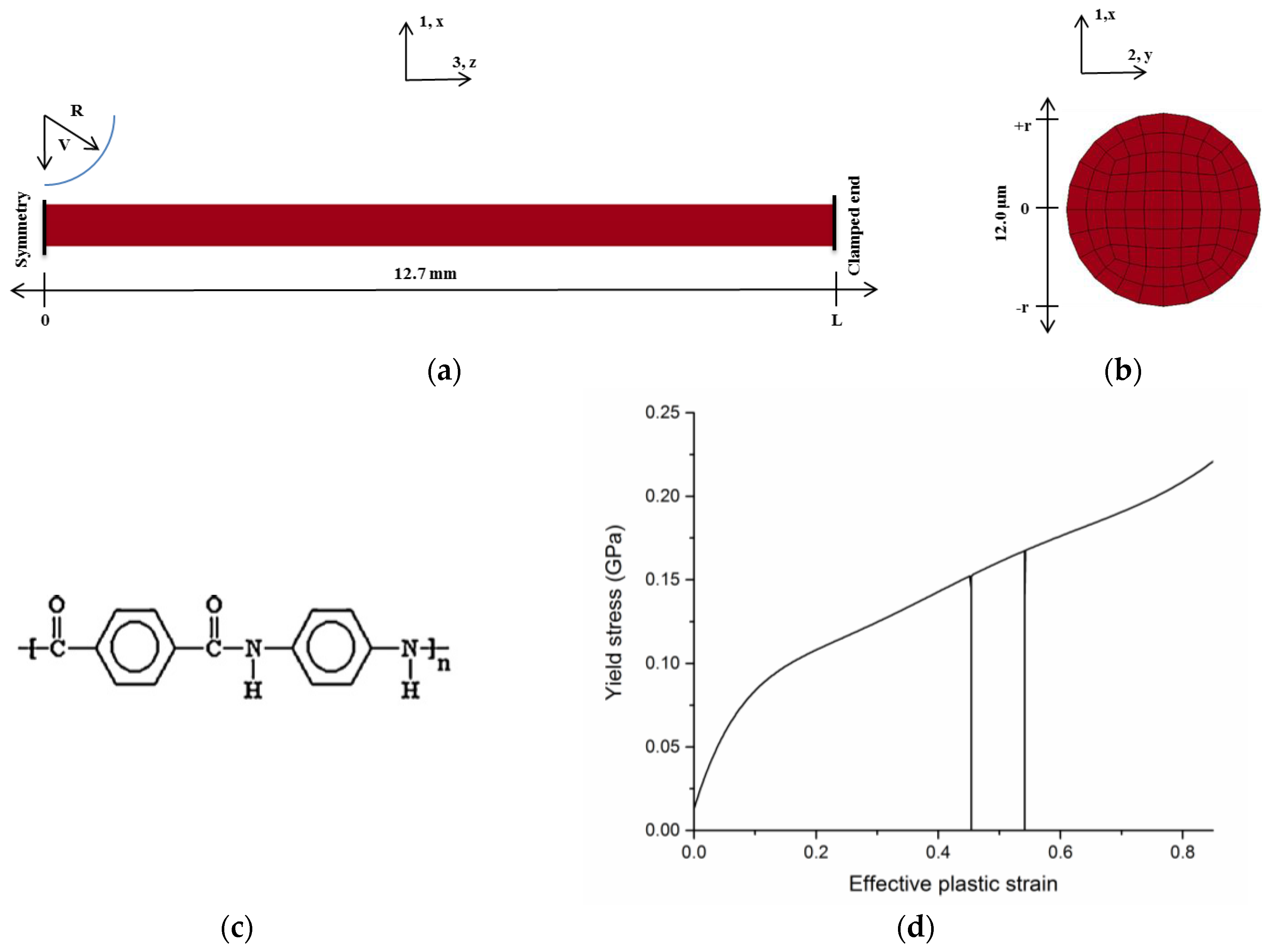
2. Single-Fiber Transverse Impact

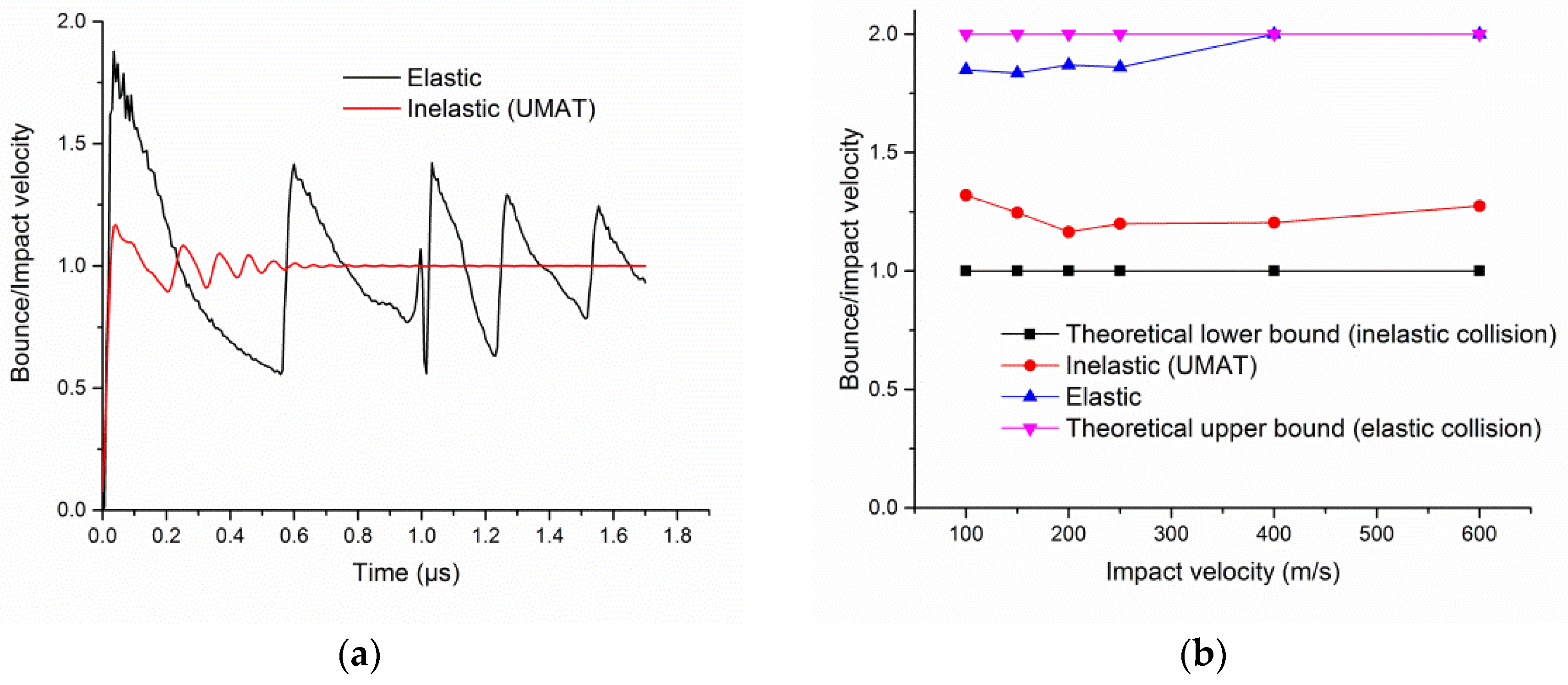
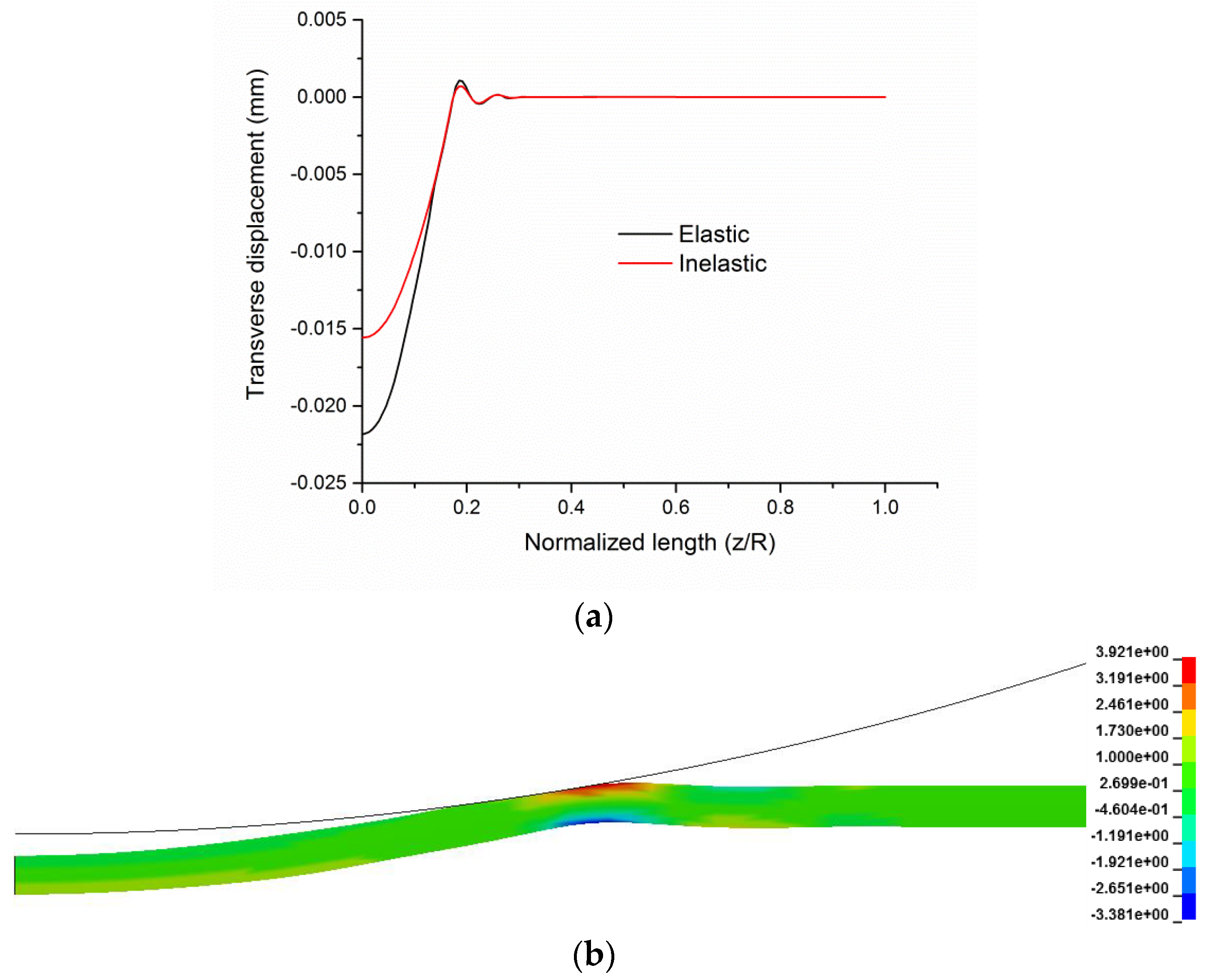
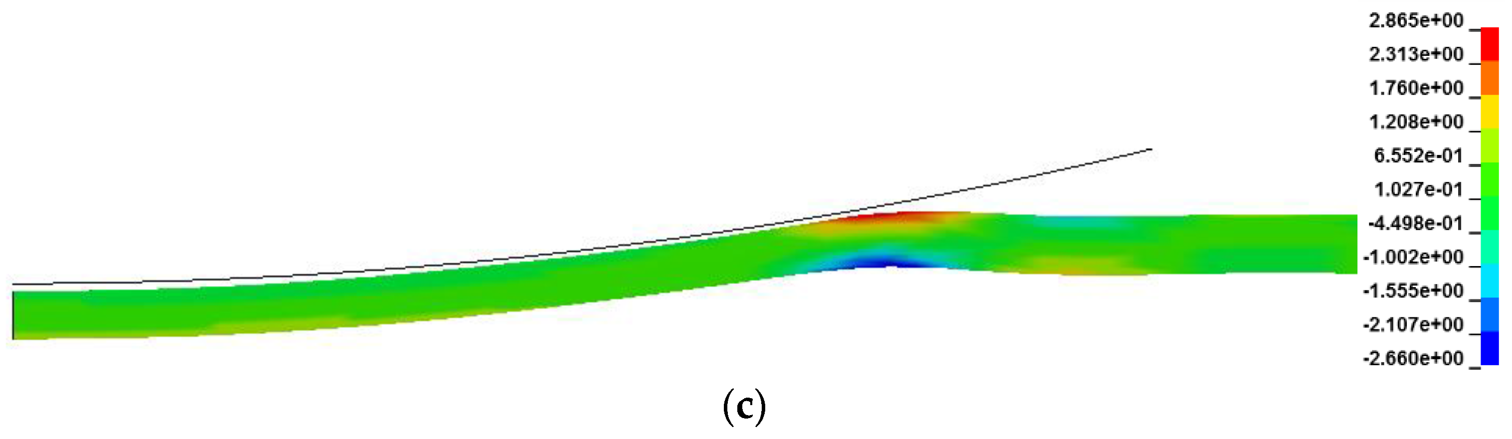
2.1. Cylindrical Projectile Impact
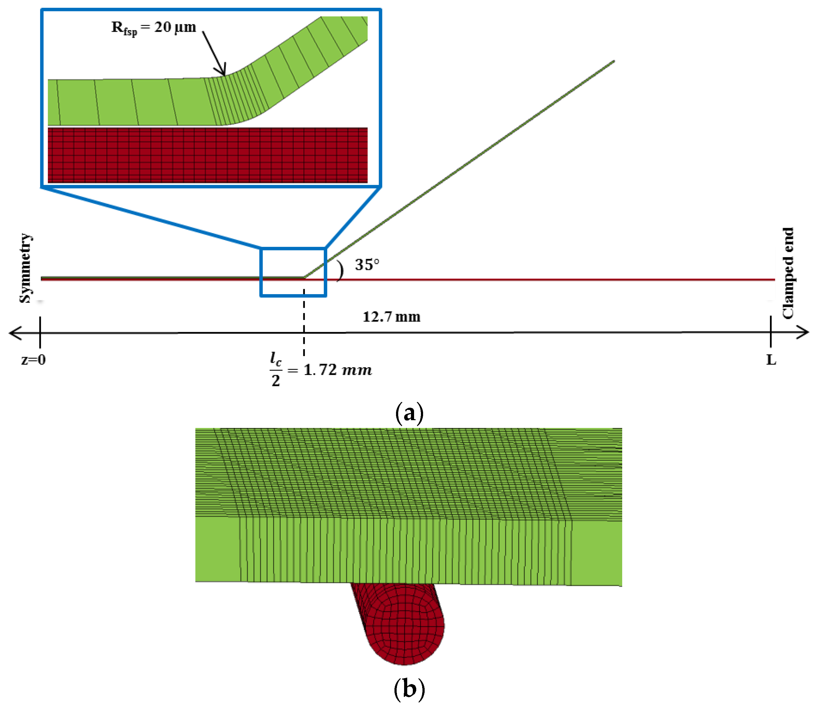
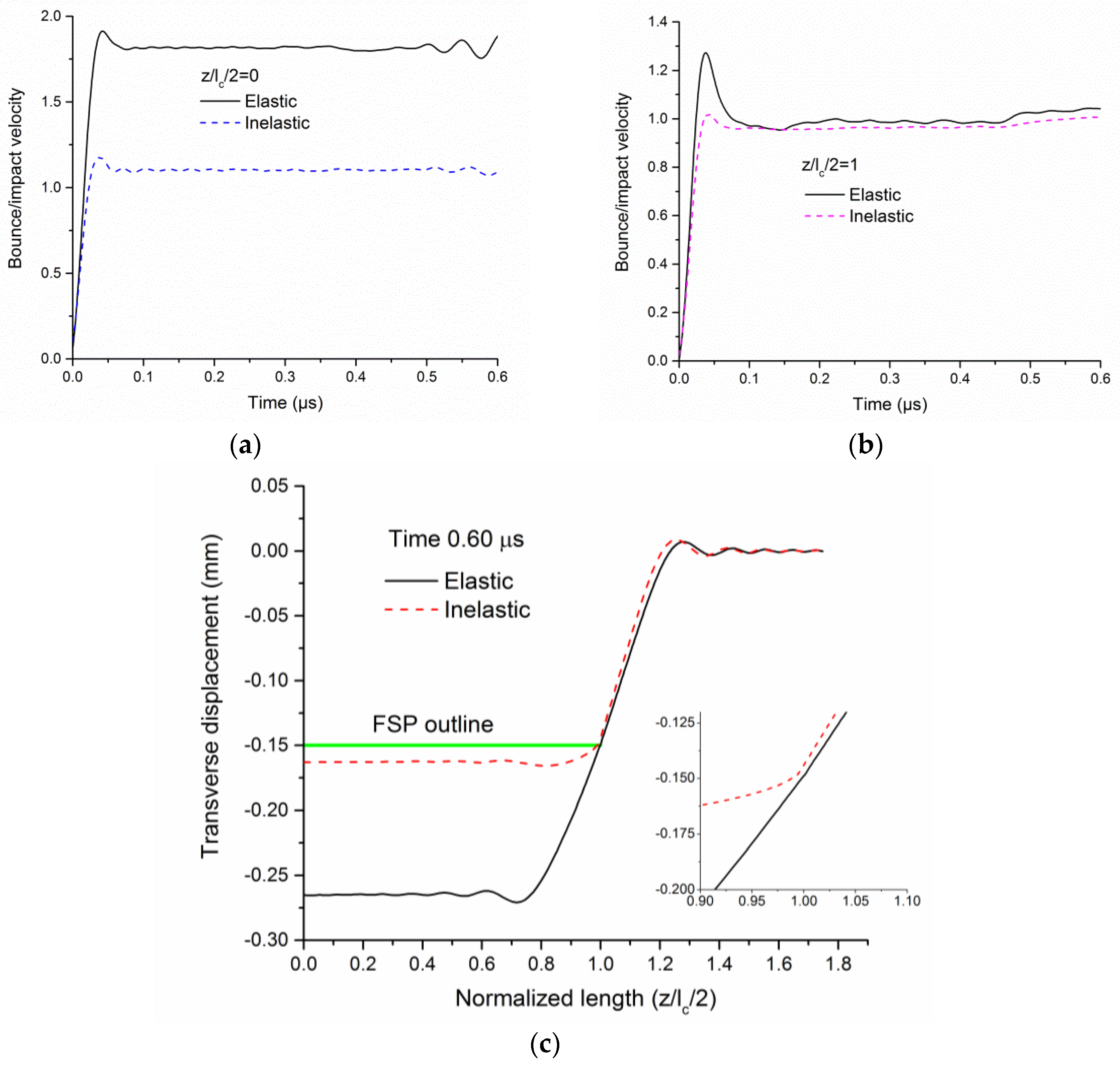
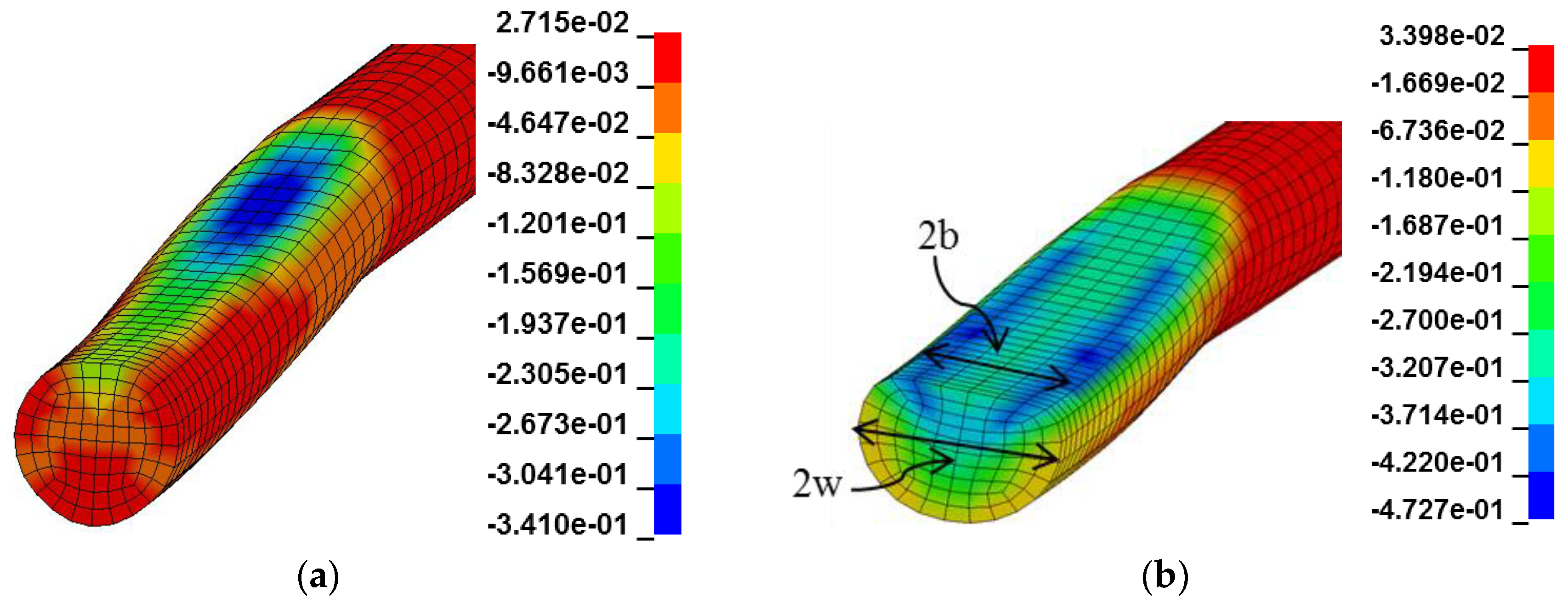
The response of a single fiber subjected to impact of a rigid cylindrical projectile of radius (R) 1.0 mm at mid-span, as shown in Figure 2, is first studied. The mass of the projectile is much higher than the mass of the fiber. The projectile is modeled as a rigid material. The contact between the projectile and the fiber is modeled using a penalty contact formulation in the commercial FE code LS-DYNA [20]. While material coordinate directions 1 and 2 represent the fiber cross-section, direction 3 is along the fiber axis. The global coordinate system is represented as x, y, and z in Figure 1. The single-fiber model is constructed using 84 reduced-integration 3D solid elements in the cross-section. This mesh discretization is determined through a mesh convergence study to accurately capture the single fiber transverse compression response under large compressive strains [11]. The mesh size along the length of the fiber is similarly determined through a mesh convergence study. Convergence in terms of axial stresses under the impact is obtained, with the maximum difference in results between the various mesh sizes being less than 2% [10]. More details on the modeling and boundary conditions can be found in [10]. The fiber is modeled as a transversely isotropic material (experimentally determined properties in Table 2) with an inelastic transverse compressive behavior using the validated user defined material (UMAT) reported in [14]. The material nonlinearity in the transverse 12-plane is modeled using a plasticity approach with Hill’s yield criterion with an initial yield stress of 13 MPa at 1.25% strain [14]. The yield stress-effective plastic strain required as input to the UMAT is shown in Figure 2c (compression shown positive). The fiber also exhibits negligible strain recovery (large residual strains) upon unloading which is modeled using a pseudo-elastic behavior [14].
The critical mass damping constant for the lowest frequency mode is 2 ω min [20] or 4 π f , where f is the lowest frequency calculated using an eigen value analysis in LS-DYNA. A typical value of 10% of critical mass damping and a damping coefficient of 0.1 for stiffness damping are used. It should be noted that bounce of the fiber (with linear elastic behavior) is predicted with damping. The ratio of bounce velocity to impact velocity for a 200 m/s impact is shown in Figure 3a. The maximum value of this ratio is 1.88 (theoretical maximum is 2.0) for the elastic fiber behavior, it is significantly reduced to 1.18 for the inelastic behavior. For the elastic case, the projectile interacts repeatedly with the fiber resulting in a series of bounces, whereas for the inelastic case, the intensity of fiber bounce during repeated projectile-fiber interactions are greatly diminished because of the dissipation due to inelastic deformation.
Figure 3b shows the ratio of bounce velocity to impact velocity for different impact velocities. In general, inelastic behavior results in a ~36% reduction in both the fiber bounce velocity and the projectile-fiber contact force. The lower contact forces are attributed to the yielding and softening response of the fiber in transverse compression. The comparison of transverse displacement between elastic and inelastic fiber behavior is shown in Figure 4a. With reduced bounce, the maximum axial strains and stresses are much lower in the inelastic fiber compared to the elastic behavior at a given impact velocity. The maximum axial tensile and axial compressive stresses for the inelastic case are 27% and 21%, respectively, lower than the elastic case for V = 200 m/s (Figure 4b,c). Flexural wave propagation in the fiber induces flexural deformation, which is sufficient to cause axial compressive kinking [10] and reduction in axial tensile strength [17]. Regardless of the fiber constitutive behavior, the models indicate a strain (stress) concentration over a small length under the projectile-fiber contact area.
Consequently, fiber breaking velocity due to axial tensile failure is sensitive to the inelastic transverse response that determines the strain concentration within the contact area, the magnitude of the average axial tensile strain within the transverse V-wave related to fiber bounce and the multi-axial loading within the projectile fiber contact area that can induce reductions in axial tensile strain to failure (e.g., axial kinking and transverse compression) [17]. To predict the breaking velocity, a failure criterion (presented later in Section 3.3) is developed and applied at each time step of the impact simulation to identify the location and time of failure, the degree of multi-axial loading and overall dynamic deformation of the fiber. These results should be extremely valuable to experimentalists.
Figure 5 shows the short time scale transverse compressive strain contours at times corresponding to maximum strain for elastic and inelastic cases. It is seen that the maximum compressive strain experienced by the fiber with inelastic behavior (~48%) is about 40% higher than the strain for fiber with elastic behavior (~34%). Permanent deformation along with multiaxial stress state is predicted by the inelastic model at these strain levels, whereas the elastic model shows elastic recovery. The contact width (2b) and compressed width (2w) indicated in Figure 5b is, in general, higher for the inelastic fiber. At the mid-span, the ratio of 2b/d = 0.91 for inelastic, and 0.48 for elastic, fiber, whereas the ratio of 2w/d = 1.16 for inelastic, and 1.0 for elastic fiber.

2.2. FSP Impact

The response of a single fiber subjected to the impact of a 0.30 caliber FSP specified by MIL-DTL-46593B is studied in this section. This impactor geometry is commonly used in experimental studies. The effect of inelastic behavior on bounce and axial waves within the contact zone will be compared to the elastic results. The FSP is modeled as a rigid material with a corner radius of 20 µm [23] as shown in Figure 6a. The projectile’s presented characteristic length (lc) is 3.45 mm. A finer mesh along the length of the fiber is used under the impact as shown in Figure 6.
The ratio of bounce velocity to impact velocity at the mid-span (z/lc/2 = 0) and at the location where the FSP corner radius contacts the fiber (z/lc/2 = 1) for a 250 m/s impact are shown in Figure 7a,b. While the inelastic behavior results in a 38% reduction in the maximum bounce velocity at the mid-span, this reduction is reduced to 20% at z/lc/2 = 1. The fiber separation from the flat face of the FSP occurs upon reaching the maximum bounce velocity. With the increase in time, the difference in the bounce velocity ratio remains constant at z/lc/2 = 0, whereas the ratio reaches one at z/lc/2 = 1 in both elastic and inelastic cases.
A higher bounce results in a bigger separation of the fiber from the projectile in the region z/lc/2 = 0 to 1 in the elastic case compared to inelastic behavior as shown in Figure 7c. The abscissa in Figure 7c is normalized using the half width of the flat face of the FSP as the characteristic length lc/2 = 1.72 mm. Once the fiber separates, the corner of the FSP is in contact with the fiber for both elastic and inelastic behavior. The lower bounce results in bending and a higher axial stress (tensile and compressive) concentration in the inelastic fiber compared to the elastic, apparent from the deformation mode shown in Figure 7c. For an FSP impact, irrespective of the fiber behavior, the models indicate there is no repeated projectile-fiber interaction. The inelastic fiber experiences significant axial tensile and axial compressive stress concentration over a small length of ~20 µm as shown in Figure 8a. Additionally, the fiber is also subjected to significant transverse compressive strains at the failure location sufficient to cause permanent deformation. While the maximum transverse compressive strain at the failure location for V = 300 m/s is 75% as shown in Figure 8b, the average strain in the fiber cross-section is 42%. The interlaminar shear deformation with a maximum engineering shear strain of 1.5% occurs at the failure location. Consequently, the fiber is subjected to multiaxial stress states (axial compression (AC), transverse compression (TC), and interlaminar shear (ILS)) during impact.
Walker and Chocron [5] report yarn breaking speed as a function of the ratio V ¯ / V and indicated the experimental KM2 yarn breaking speed is in the range corresponding to the ratio 1.68 V f / V 1.72 . That is, the bounce velocity of the yarn is at least 68% greater than the impact velocity to explain the reduction in experimental breaking speed. However, this study considering the physically-observed inelastic fiber behavior show significantly reduced bounce velocity as a consequence of the inelastic collision. Therefore, the reduction in experimental breaking speed compared to theoretical Smith theory [3] may be attributed to strain (stress) concentration and property degradation mechanisms due to the multiaxial stress states at the location of fiber failure.

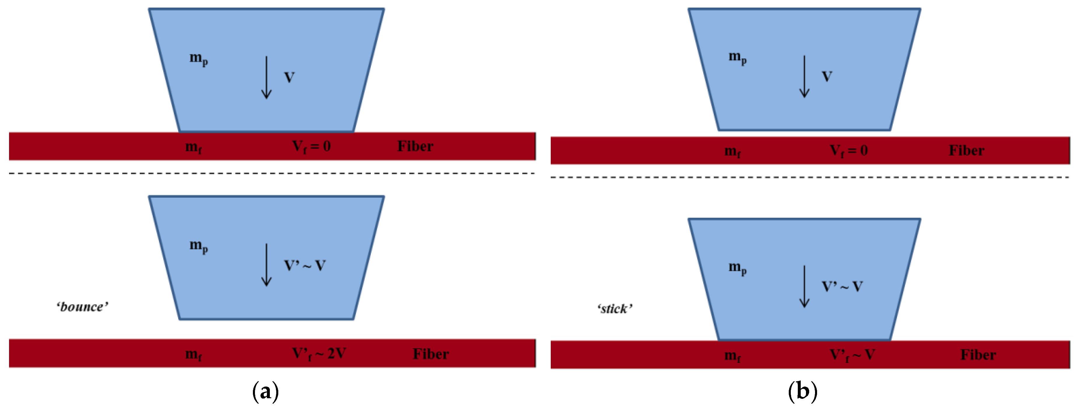
3. Multiaxial Loading and Failure

The multiaxial loading induced by impact is first quantified in order to predict the failure and, hence, the breaking speed of the fiber.

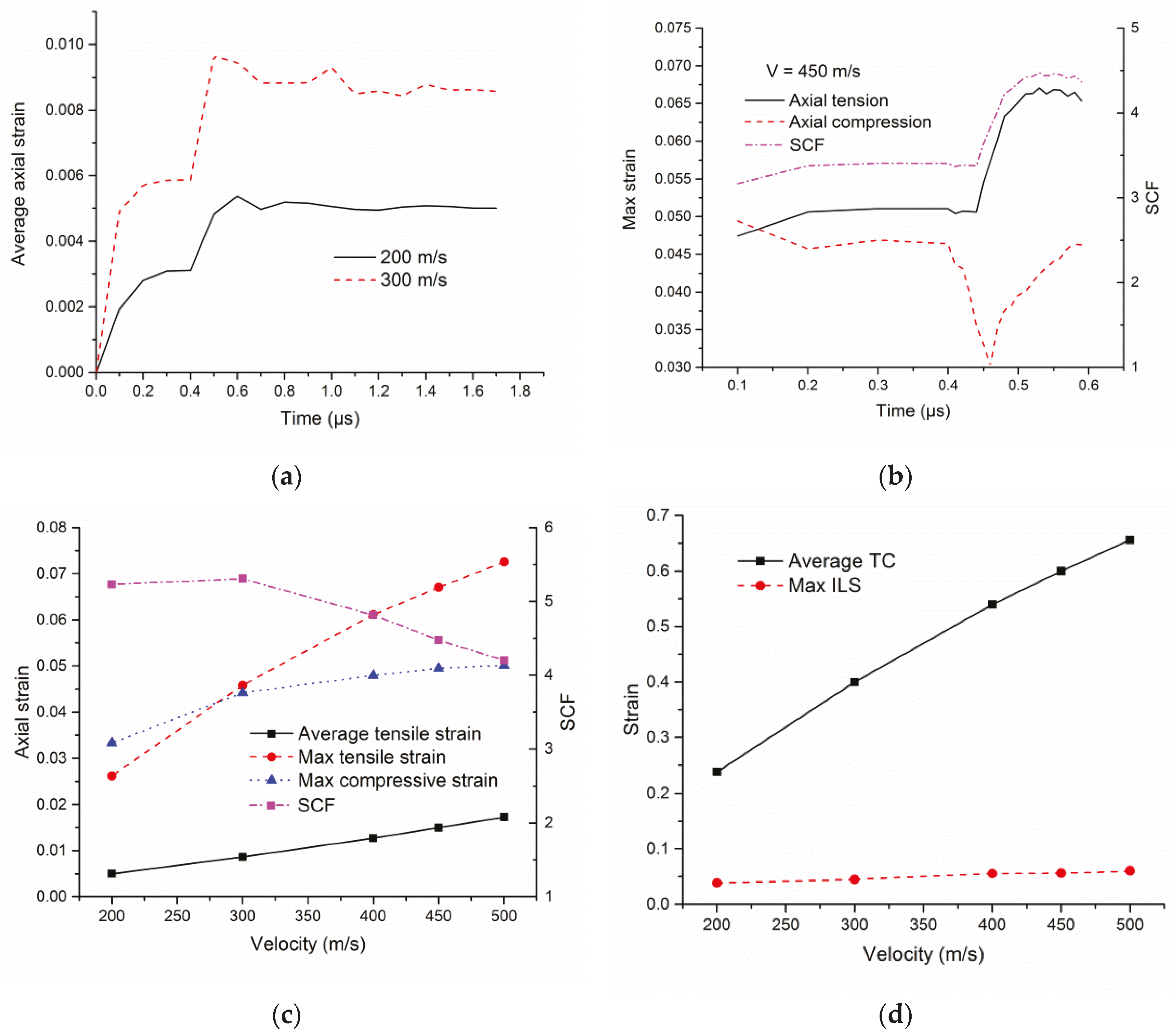
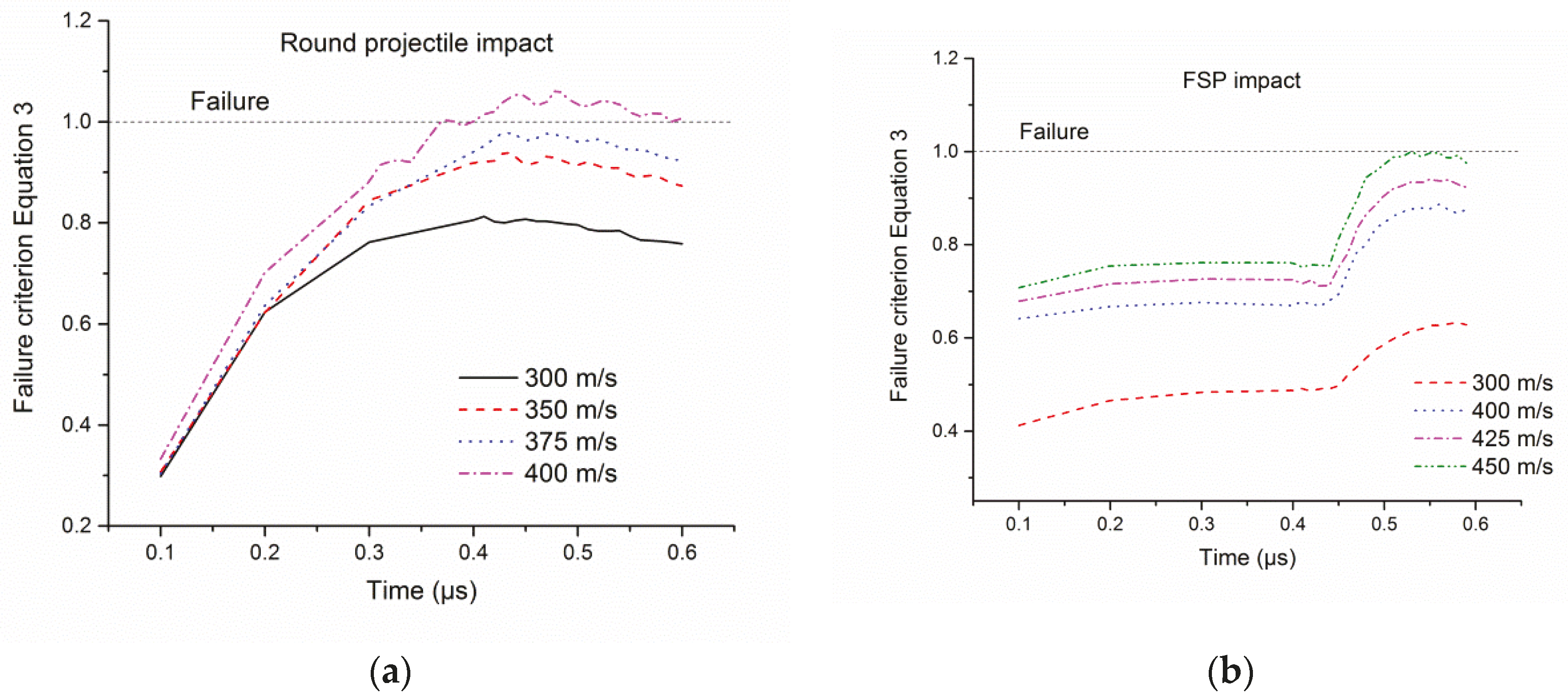
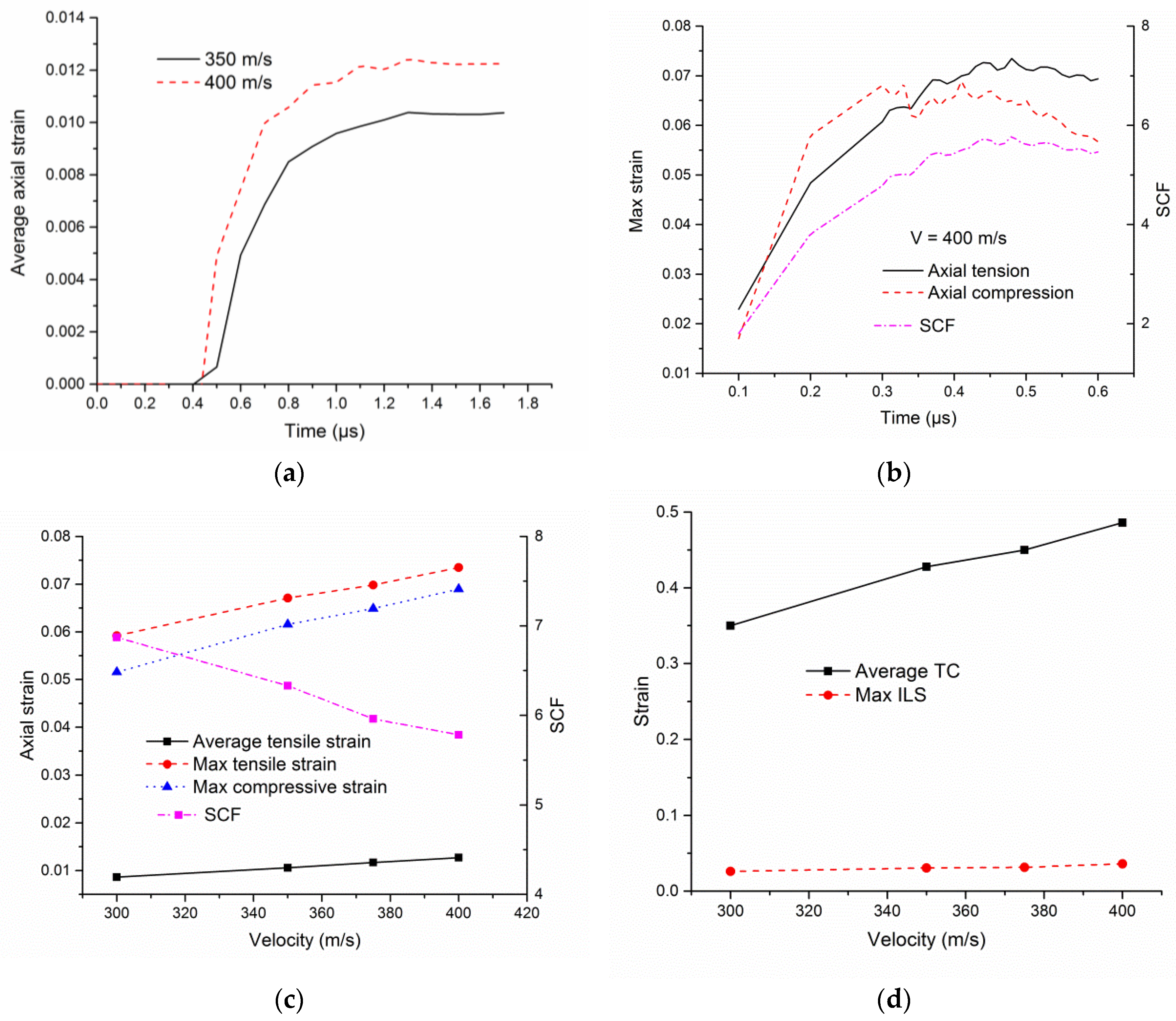
3.1. Cylindrical Projectile Impact

The time taken for the longitudinal wave to reach the boundary from the impact location is 1.66 µs. The average axial strain plotted at a location z/R = 0.91 for two different impact velocities is shown in Figure 9a. The average axial tensile strain correlates well with the Smith solution Equation (1). Figure 9b shows the time history of maximum axial tensile, axial compressive (compressive strains shown positive) and strain concentration factor (SCF) during the short time scale during which failure is predicted (failure prediction is discussed in Section 3.3). It should be noted that these maximum values occur at different locations in the fiber (within the projectile radius) at each time. SCF is defined as the maximum axial tensile strain divided by the plateau level of the average axial tensile strain in Figure 9a. In the quasi-static round projectile (radius R = 3.8 mm) loading [18], there is no axial strain concentration in the fiber engaging the entire 550 mm gage length [17] whereas, in the dynamic impact loading, the cylindrical projectile (radius R = 3.8 mm) repeatedly interacts with the fiber as the contact evolves dynamically along the projectile geometry. Therefore, the projectile-fiber contact location moves along the projectile surface and the location of maximum axial strain moves along the length of the fiber. An axial strain concentration occurs due to the dynamic evolution of contact zone along the projectile geometry. This might explain the experimental observation [24] of yarn failure in multiple locations when subjected to a round projectile impact.
The maximum axial tensile strains are much higher than their average counterparts as shown in Figure 9c. The maximum axial tensile strain occurs over a length (Lc) of approximately 20 µm. The axial compressive strains are high enough to induce compressive kinking and reduction in tensile strain to failure of the fiber [17]. While axial tensile and compressive strains increase with an increase in impact velocity, SCF decreases due to a higher increase in the average axial tensile strain. The maximum value of the average TC strains (compressive strains shown positive) in the fiber cross-section during impact is plotted as a function of impact velocity in Figure 9d. The magnitudes of these transverse compressive strains are sufficient to induce fibrillation and reduction in tensile strain to failure of the fiber within the projectile-fiber contact [17]. The maximum engineering ILS strains are relatively small for all impact velocities, as shown in Figure 9d. It should be noted that, in the quasi-static case using the same impactor, the model predicted [17] all other deformation modes including AC, TC, and ILS to be negligible for all loading angles. This comparison clearly proves that dynamic loading effects on multi-axial loading of the fiber at the failure location are important to include in the failure theory.

3.2. FSP Impact

In the quasi-static FSP loading [18], there is a maximum axial strain concentration of 4.0 at a 47° failure angle in the fiber over a length of approximately 23 µm [17]. The average axial strain plotted at a location 100 µm away (z = 1.82 mm see Figure 6a) from the corner radius of the FSP for two different impact velocities is shown in Figure 10a. Upon impact, the fiber immediately separates from the flat face of the FSP and, effectively, impact is under the corner radius of the projectile. Thus, longitudinal waves travel in both fiber directions (outward away from the mid-span and inward towards the mid span) from the corner radius. The time taken for the inward-traveling longitudinal wave to travel from the corner radius to mid-span is 0.224 µs. This wave reflects at the mid-span with an increase in the strain. After this, the average axial tensile strains stabilize to the Smith solution (Equation (1)). Figure 10b shows the time history of maximum axial tensile, axial compressive (compressive strains shown positive) and SCF during the short time scale during which failure is predicted (failure prediction discussed in Section 3.3). Unlike a round projectile impact, the maximum values occur under the corner radius of the projectile at all times.
Similar to quasi-static loading, the maximum axial tensile strains are much higher than their average counterparts as shown in Figure 10c. The strain concentration occurs over a contact length of approximately 20 µm under the projectile-fiber contact. The axial compressive strains are high enough to induce compressive kinking and reduction in tensile strain to failure of the fiber [17]. While axial tensile and compressive strains increase with increase in impact velocity, SCF decreases due to a higher increase in the average axial tensile strain. In the quasi-static FSP loading [18], an SCF of 2.19 is predicted at a 28° failure angle in the fiber [17]. However, in the dynamic case, at a 27.5° angle (corresponding to a velocity of 400 m/s), the SCF (4.8) exceeds the quasi-static value by two-fold. The maximum value of the average TC strains (compressive strains shown positive) in the fiber cross-section during impact is plotted as a function of impact velocity in Figure 10d. The magnitudes of these transverse compressive strains are sufficient to induce fibrillation and reduction in tensile strain to failure of the fiber within the projectile-fiber contact [17]. The maximum engineering ILS strains are relatively small for all impact velocities, as shown in Figure 10d.
The time evolution of strains due to multi-axial loading presented in Figure 9 and Figure 10 for the cylindrical and FSP are used as inputs to the failure criterion presented next.

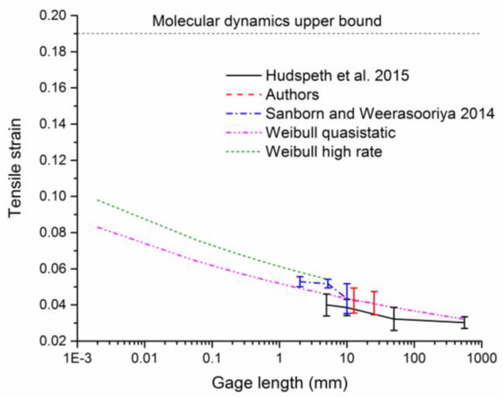
3.3. Failure Criterion

The breaking speed predictions are complicated by the fact that Kevlar KM2 single fibers [23] and yarns [25] exhibit a gage length dependent statistical distribution of axial tensile strain to failure. Figure 11 shows the gage length-dependent quasi-static axial tensile failure strain of KM2 single-fiber [26]. Figure 11 also shows the average failure strain predicted as a function of gage length, to smaller gage lengths, using the Weibull model in Equation (2):
P ( ε , L ) = 1 exp [ L L 0 ( ε ε 0 ) m ]
where L0 is the reference gage length (12.7 mm) at which the scale ε 0 = 0.044 and shape parameters m = 13.25 are determined, and P ( ε , L ) is the cumulative probability of failure of a gage length L at a strain level ε . In general, failure strains exhibit an increasing trend with decreasing gage length and plateau at higher gage lengths. The tensile failure strain of a perfect Kevlar crystal chain calculated from molecular dynamics is about 19% [27] which may be considered as the intrinsic strength of the material. Strain rate effects may play a role in predicting the fiber failure. Sanborn and Weerasooriya [26] showed a constant 18% increase in the failure strength of single fibers at high strain rate (1200 1/s) compared to quasi-static strain rates for 2 and 5 mm gage lengths. The predicted local maximum axial strain rates in the fiber are of the order of 106 1/s. A constant 18% increase in the average failure strain due to strain rate effect is assumed for all gage lengths, as shown in Figure 11 (Weibull high rate curve). While the strain rate effects increase the tensile strength [26], multiaxial loading effects degrade the strength [28,29,30].
The failure criterion developed [17] based on the analyses and validation of multiaxial quasi-static loading experiments is extended for the dynamic loading and given in Equation (3):
ε 3 , max ( t ) ε 3 , fail ( t ) = 1
where:
ε 3 , max ( t ) = SCF ( t ) × ε 3 , avg ( t )
ε 3 , fail ( t ) = ε 3 ( L c ,   ACr ,   TCr ,   ILSr , t )
ε 3 , fail ( t ) = ε 3 ( L c ) × ( 1 + SR ) × ( 1 ACr ) × ( 1 TCr ) × ( 1 ILSr )
where ε3,max is the maximum axial tensile strain predicted by the model, ε3,fail is the axial tensile failure strain, which is a function of the failure strain based on the Weibull model at a gage length equal to contact length (Lc), (1 − ACr), (1 − TCr), and (1 − ILSr) are the reduction factors in the respective individual deformation modes based on the maximum levels of loading in the time history. ACr, TCr, and ILSr are the degradation percentages in the respective individual deformation modes. SR is the strain rate factor to account for increase in the failure strain at high strain rates, SR = 0.18.
The tensile strain to failure, ε3(Lc) used in the criterion is based on the Weibull model, where the length (Lc) of the fiber subjected to the strain concentration due to projectile-fiber contact. The strain to failure at a 50% probability of failure increases from 4.24% at 12.7 mm (gage length used in the experiment) to 6.98% at a 20 µm gage length calculated for both cylindrical projectile and FSP.
Based on the predicted strains in different deformation modes, the total reduction factor is calculated over time. The AC strains (Figure 9c and Figure 10c) are high enough to cause axial compressive kinking and a reduction in tensile failure strain. Based on the experimental results and discussion in [17], a reduction by a factor of (1 − ACr = 1 − 7% = 0.93) is assumed for all times in Equation (3). The maximum level of average TC strains predicted by the models (Figure 9d and Figure 10d) during the time history are used to identify the reduction factors. For example, at 50% average TC strain, 1 − TCr = 0.90 [17]. The maximum ILS strains (Figure 9d and Figure 10d) experienced by the fiber are negligible (1 − ILSr = 1.0) during both round and FSP impact. To predict the location of failure and the breaking speed for each projectile type, the failure criterion is applied incrementally due to the inherent nonlinearity associated with the inelastic material response, evolving contact area and reduction factors. The failure criterion versus time is plotted in Figure 12, where failure occurs when the failure criterion equals unity. The inelastic model predicts a breaking speed of 400 m/s and 450 m/s for cylindrical and FSP, and failure under projectile-fiber contact, respectively. The time of failure falls in the range of 0.4 to 0.55 µs.
The fiber bounce and axial stresses for an elastic fiber behavior is much higher than the inelastic case as discussed in Section 2. A breaking speed of 300 m/s is predicted by applying the failure criterion (Equation (3)) for elastic fiber behavior for the cylindrical projectile. The corresponding inelastic breaking speed (400 m/s) is 33% higher than the elastic case due to the reduced bounce. Similarly for FSP, a breaking speed of 400 m/s is predicted for elastic behavior. The inelastic FSP breaking speed (450 m/s) is 12% higher than the elastic case.
For both cylindrical projectile and FSP impact, an axial tensile strain (stress) concentration (5.8 and 4.5, respectively, at failure velocity) occurs over a small length of the order of microns, in addition to multiaxial loading and axial strain (stress) gradients in the fiber cross-section under the projectile-fiber contact. The results are strikingly similar to the quasi-static multiaxial loading analyses [17] in that the maximum axial tensile strains are much higher than the experimentally-measured average failure strain. It should be noted that the Smith equation (Equation (1)) does not account for these projectile-fiber contact-induced strain concentration and multiaxial loading effects. These results suggests that fiber failure is initiated based on a gage length dependent maximum axial tensile strain during impact.

4. Conclusions

The role of inelastic transverse compressive behavior and multiaxial loading of Kevlar KM2 single fiber during transverse impact onto a single fiber is studied using a 3D fiber length-scale FE model. The fiber is subjected to transverse impact using a rigid cylindrical projectile and a 0.30 caliber FSP. The bounce (assuming elastic collision) of the material due to projectile-fiber contact interactions is reported as one of the mechanisms responsible for experimentally observed lower yarn breaking speed compared to the Smith theory. It should be noted that Smith theory does not consider the effect of projectile geometry, inelastic material behavior, and multiaxial stress states. This study shows that, in general, the fiber bounce velocity is significantly reduced (by 36%) for both cylindrical and FSP, considering the nonlinear inelastic behavior compared to an elastic behavior assumed in the literature. With reduced bounce, the maximum axial tensile strains are, in general, lower in the inelastic fiber compared to an elastic behavior for a given impact velocity. Thus, the evolution of axial strains and, hence, the fiber failure is found to be sensitive to the inelastic fiber behavior. Inelastic behavior results in a significantly higher permanent transverse compressive deformation in the fiber sufficient to cause permanent deformation and reduction in tensile strain to failure.
This study also shows the presence of multiaxial stress states in the fiber during impact. The fiber experiences transverse compression, axial compression, axial tension, and transverse shear deformations. In addition to multiaxial loading, projectile-fiber contact induces an axial strain (stress) concentration over a small length under the projectile-fiber contact. Single-fiber breaking speeds are predicted by applying a failure criterion based on the maximum axial tensile strain incorporating the gage length, strain rate, and multiaxial loading degradation effects. It is worth noting that the failure criterion is based on the quasi-static multiaxial loading of fibers. The only strain rate effect considered is the effect of strain rate on the fiber tensile strength. Furthermore, the failure criterion assumes that the degradation of tensile strength due to multiaxial loading is independent of the strain rate which is a topic for future investigation. For quasi-static round projectile loading, with a projectile radius much higher than the fiber diameter, no axial strain concentration was predicted [17]. However, in the case of a cylindrical projectile impact, an axial strain concentration occurs due to the dynamic evolution of the contact zone along the projectile geometry. The effect of multiaxial loading on the fiber failure strain is important to fully understand failure modes during transverse impact. Considering the inelastic collision (lack of bounce), the experimentally-observed lower breaking speed for yarns than Smith theory may be attributed to the strain concentration and multiaxial stress states that reduce strain to failure in the fiber. It should be noted that the approach presented in this paper may also be applicable for other fibers, including gel-spun ultra-high molecular weight polyethylene (UHMWPE) [31] and carbon nanotube (CNT) [32] fibers. The failure of fibers within a yarn during impact is complicated due to the fiber-fiber interactions, geometric and material property variations among the fibers, and needs further investigation. Additionally, strain rate effects and multiaxial loading may play a role in the fiber failure during yarn impact. The effect of strain rate on the tensile strain degradation factors is also a topic for future studies.

Acknowledgments

Research was sponsored by the Army Research Laboratory and was accomplished under Cooperative Agreement Number W911NF-12-2-0022. The views and conclusions contained in this document are those of the authors and should not be interpreted as representing the official policies, either expressed or implied, of the Army Research Laboratory or the U.S. Government. The U.S. Government is authorized to reproduce and distribute reprints for Government purposes notwithstanding any copyright notation herein.

Author Contributions

J.W.G.J. and S.S. conceived and designed the simulations. S.S. conducted the simulations. S.S., J.W.G.J. and M.K. contributed to analysis and manuscript writing.

Conflicts of Interest

The authors declare no conflicts of interest.

References

  1. Krishnan, K.; Sockalingam, S.; Bansal, S.; Rajan, S. Numerical simulation of ceramic composite armor subjected to ballistic impact. Compos. B 2010, 41, 583–593. [Google Scholar] [CrossRef]
  2. Sockalingam, S.; Chowdhury, S.C.; Gillespie, J.W.; Keefe, M. Recent advances in modeling and experiments of Kevlar ballistic fibrils, fibers, yarns and flexible woven textile fabrics—A review. Text. Res. J. 2016. [Google Scholar] [CrossRef]
  3. Smith, J.C.; McCrackin, F.L.; Schiefer, H.F. Stress-Strain Relationships in Yarns Subjected to Rapid Impact Loading: Part V: Wave Propagation in Long Textile Yarns Impacted Transversely. Text. Res. J. 1958, 28, 288–302. [Google Scholar] [CrossRef]
  4. Chocron, S.; Kirchdoerfer, T.; King, N.; Freitas, C.J. Modeling of fabric impact with high speed imaging and nickel-chromium wires validation. J. Appl. Mech. 2011, 78, 051007. [Google Scholar] [CrossRef]
  5. Walker, J.D.; Chocron, S. Why impacted yarns break at lower speed than classical theory predicts. J. Appl. Mech. 2011, 78, 051021. [Google Scholar] [CrossRef]
  6. Hudspeth, M.; Chu, J.; Jewell, E.; Lim, B.; Ytuarte, E.; Tsutsui, W.; Horner, S.; Zheng, J.; Chen, W. Effect of projectile nose geometry on the critical velocity and failure of yarn subjected to transverse impact. Text. Res. J. 2016. [Google Scholar] [CrossRef]
  7. Meyers, M.A. Dynamic Behavior of Materials; John Wiley & Sons: New York, NY, USA, 1994. [Google Scholar]
  8. Prosser, R.A.; Cohen, S.H.; Segars, R.A. Heat as a factor in the penetration of cloth ballistic panels by 0.22 caliber projectiles. Text. Res. J. 2000, 70, 709–722. [Google Scholar] [CrossRef]
  9. Tan, V.; Lim, C.; Cheong, C. Perforation of high-strength fabric by projectiles of different geometry. Int. J. Impact Eng. 2003, 28, 207–222. [Google Scholar] [CrossRef]
  10. Sockalingam, S.; Gillespie, J.W., Jr.; Keefe, M. Dynamic modeling of Kevlar KM2 single fiber subjected to transverse impact. Int. J. Solids Struct. 2015, 67–68, 297–310. [Google Scholar] [CrossRef]
  11. Sockalingam, S.; Gillespie, J.W., Jr.; Keefe, M. On the transverse compression response of Kevlar KM2 using fiber-level finite element model. Int. J. Solids Struct. 2014, 51, 2504–2517. [Google Scholar] [CrossRef]
  12. Sockalingam, S.; Gillespie, J.W.; Keefe, M. Modeling the fiber length-scale response of Kevlar KM2 yarn during transverse impact. Text. Res. J. 2016. [Google Scholar] [CrossRef]
  13. McAllister, Q.P.; Gillespie, J.W.; VanLandingham, M.R. Evaluation of the three-dimensional properties of Kevlar across length scales. J. Mater. Res. 2012, 27, 1824–1837. [Google Scholar] [CrossRef]
  14. Sockalingam, S.; Bremble, R.; Gillespie, J.W.; Keefe, M. Transverse compression behavior of Kevlar KM2 single fiber. Compos. A 2016, 81, 271–281. [Google Scholar] [CrossRef]
  15. Rao, M.P.; Nilakantan, G.; Keefe, M.; Powers, B.M.; Bogetti, T.A. Global/Local Modeling of Ballistic Impact onto Woven Fabrics. J. Compos. Mater. 2009, 43, 445–467. [Google Scholar] [CrossRef]
  16. Nilakantan, G.; Keefe, M.; Bogetti, T.A.; Adkinson, R.; Gillespie, J.W., Jr. On the finite element analysis of woven fabric impact using multiscale modeling techniques. Int. J. Solids Struct. 2010, 47, 2300–2315. [Google Scholar] [CrossRef]
  17. Sockalingam, S.; Gillespie, J.W., Jr.; Keefe, M. Influence of multiaxial loading on the failure of Kevlar KM2 single fiber. Text. Res. J. 2016. [Google Scholar] [CrossRef]
  18. Hudspeth, M.; Li, D.; Spatola, J.; Chen, W.; Zheng, J. The effects of off-axis transverse deflection loading on the failure strain of various high-performance fibers. Text. Res. J. 2015. [Google Scholar] [CrossRef]
  19. Heru Utomo, B.; Broos, J. Dynamic material behavior determination using single fiber impact. In Proceedings of the 25th Conference and Exposition on Structural Dynamics 2007, IMAC-XXV, Orlando, FL, USA, 19–22 February 2007; p. 7.
  20. Hallquist, J.O. LS-DYNA Theory Manual; Livermore Software Technology Corporation: Livermore, CA, USA, 2006. [Google Scholar]
  21. Cheng, M.; Chen, W.; Weerasooriya, T. Mechanical Properties of Kevlar® KM2 Single Fiber. J. Eng. Mater. Technol. 2005, 127, 197–203. [Google Scholar] [CrossRef]
  22. Leal, A.A.; Deitzel, J.M.; Gillespie, J.W. Compressive strength analysis for high performance fibers with different modulus in tension and compression. J. Compos. Mater. 2009, 43, 661–674. [Google Scholar] [CrossRef]
  23. Hudspeth, M.; Chen, W.; Zheng, J. Why the Smith theory over-predicts instant rupture velocities during fiber transverse impact. Text. Res. J. 2015. [Google Scholar] [CrossRef]
  24. Hudspeth, M.C. Multi-Axial Failure of High-Performance Fiber during Transverse Impact. Ph.D. Thesis, Purdue University, West Lafayette, IN, USA, 2016. [Google Scholar]
  25. Nilakantan, G.; Obaid, A.A.; Keefe, M.; Gillespie, J.W. Experimental evaluation and statistical characterization of the strength and strain energy density distribution of Kevlar KM2 yarns: Exploring length-scale and weaving effects. J. Compos. Mater. 2011, 45, 1749–1769. [Google Scholar] [CrossRef]
  26. Sanborn, B.; Weerasooriya, T. Quantifying damage at multiple loading rates to Kevlar KM2 fibers due to weaving, finishing, and pre-twist. Int. J. Impact Eng. 2014, 71, 50–59. [Google Scholar] [CrossRef]
  27. Chowdhury, S.C.; Haque, B.Z.; van Duin, A.C.T.; Bogetti, T.A.; Gillespie, J.W., Jr. Study of the Mechanical Properties of Kevlar Fibril using Molecular Dynamics Simulations. In Proceedings of the SAMPE Conference, Baltimore, MD, USA, 18–21 May 2015.
  28. Cheng, M.; Chen, W.; Weerasooriya, T. Experimental investigation of the transverse mechanical properties of a single Kevlar® KM2 fiber. Int. J. Solids Struct. 2004, 41, 6215–6232. [Google Scholar] [CrossRef]
  29. Obaid, A.A.; Yarlagadda, S.; Gillespie, J. Combined effects of kink bands and hygrothermal conditioning on tensile strength of polyarylate liquid crystal co-polymer and aramid fibers. J. Compos. Mater. 2015, 50, 339–350. [Google Scholar] [CrossRef]
  30. Bazhenov, S.; Goncharuk, G.; Bobrov, A. Effect of transverse compression on the tensile strength of aramid yarns. Dokl. Phys. Chem. 2015, 462, 115–117. [Google Scholar] [CrossRef]
  31. McDaniel, P.B.; Sockalingam, S.; Deitzel, J.; Gillespie, J.W., Jr.; Keefe, M.; Bogetti, T.A.; Casem, D.T.; Weerasooriya, T. The effect of fiber meso/nanostructure on the transverse compression response of ballistic fibers. Compos. A 2017, 94, 133–145. [Google Scholar] [CrossRef]
  32. Li, Y.; Lu, W.; Sockalingam, S.; Gu, B.; Sun, B.; Gillespie, J.W., Jr.; Chou, T. Electromechanical behavior of carbon nanotube fibers under transverse compression. J. Phys. D 2017, 50, 085303. [Google Scholar] [CrossRef]
Figure 1. Perfectly (a) elastic collision and (b) inelastic collision.
Fibers 05 00009 g001
Figure 2. Half-symmetric 3D single-fiber model (not to scale); (a) cylindrical impact at the mid-span; (b) fiber cross-section; (c) structure of Kevlar; and (d) yield stress-effective plastic strain in transverse compression.
Fibers 05 00009 g002
Figure 3. Ratio of bounce velocity to impact velocity for a rigid 1.0 mm radius cylindrical projectile (a) at 200 m/s; and (b) function of impact velocity.
Fibers 05 00009 g003
Figure 4. Cylindrical projectile impact at V = 200 m/s at 0.0784 µs: (a) transverse displacement, axial stress contours in GPa; (b) elastic; and (c) inelastic.
Fibers 05 00009 g004aFibers 05 00009 g004b
Figure 5. Contours of transverse compressive strains at a 200 m/s impact at 0.03 µs; (a) elastic; and (b) inelastic.
Fibers 05 00009 g005
Figure 6. Half-symmetric 3D single-fiber model: (a) FSP impact at the mid-span; and (b) fiber cross-section.
Fibers 05 00009 g006
Figure 7. FSP impact at 250 m/s: (a) bounce/impact velocity at z/lc/2 = 0; (b) bounce/impact velocity at z/lc/2 = 1; and (c) transverse displacement at 0.60 µs.
Fibers 05 00009 g007
Figure 8. FSP impact at 300 m/s, inelastic fiber behavior: (a) contours of axial stresses in GPa at 0.50 µs; and (b) transverse compressive strains at 0.05 µs.
Fibers 05 00009 g008
Figure 9. Cylindrical impact inelastic fiber behavior: (a) evolution of average axial strains; (b) evolution of axial tensile and compressive strains; (c) axial strain and SCF as a function of velocity; and (d) TC strain as a function of velocity.
Fibers 05 00009 g009
Figure 10. FSP impact inelastic fiber behavior: (a) evolution of average axial strains; (b) evolution of axial tensile and compressive strains; (c) axial strain and SCF as a function of velocity; and (d) TC strain as a function of velocity.
Fibers 05 00009 g010
Figure 11. Single Kevlar KM2 fiber tensile failure strain as a function of gage length.
Fibers 05 00009 g011
Figure 12. Failure prediction: (a) failure criterion for a cylindrical projectile; and (b) failure criterion for FSP.
Fibers 05 00009 g012
Table 1. Yarn breaking speed [5,6,19]. PBO: polybenzoxazole.
Yarn–ProjectileExperimental (m/s)Theoretical (m/s)
Kevlar KM2 800 denier–FSP621–634926
Kevlar KM2 600 denier–FSP480–645926
Kevlar KM2 600 denier–0.30 cal round540–700926
Aramid–Saddle400926
Dyneema–FSP5501100
PBO–FSP5661105
Table 2. Transversely isotropic properties of a Kevlar KM2 single-fiber [21,22].
ρ(g/cm3)d (µm)E1 (GPa)E3 (GPa)G13 (GPa)ν31ν12σtf (GPa)σcf (GPa)
1.4512.01.3084.6224.400.600.403.880.68

