
Ultra-Low-Power Circuits for Intermittent Communication

1
Department of Industrial Engineering, University of Trento, 38123 Trento, Italy
2
INSTM National Interuniversity Consortium of Materials Science and Technology, 50121 Firenze, Italy
3
Department of Information Engineering and Computer Science, University of Trento, 38123 Trento, Italy
*
Author to whom correspondence should be addressed.
J. Low Power Electron. Appl. 2022, 12(4), 60; https://doi.org/10.3390/jlpea12040060
Submission received: 13 September 2022
/
Revised: 21 October 2022
/
Accepted: 8 November 2022
/
Published: 13 November 2022
(This article belongs to the Special Issue Energy-Harvesting and Self-Powered Devices)
Abstract
:Self-sustainable energy harvesting for Internet of Things devices is challenging since ambient energy may be sporadic and unpredictable. This situation leads to frequent power failures that lead to intermittent operations, which prevent the reliability of data communications. This article presents fundamental hardware circuitry that enables reliable intermittent communications over wireless batteryless node networks. We emphasize two main mechanisms that ensure energy awareness and reliability: energy status-sharing and synchronized operation. We introduce novel low-power and self-sustainable plug-and-play circuits to support these mechanisms.
1. Introduction
For decades, designers and researchers have proposed many devices and applications that deal with ambient sensing and send data over the Internet, i.e., the so-called ubiquitous sensing or the Internet of Things (IoT). The IoT’s market-growth trend involves billions of devices that are sold each year as well as massive hype for industry and research, bringing several challenges and new opportunities.
A significant challenge arises from the energy supply of IoT devices since the majority include batteries that provide energy to electronic circuits. On the one hand, batteries have several advantages, such as making IoT devices wireless and portable. Furthermore, battery-equipped devices can rely on specific and well-known stored energy types. Generally speaking, designers select the battery size that supports the whole application life cycle. Thus, power failure never occurs during an operation unless reaching the end of the battery’s life cycle. Despite the benefits mentioned above, battery-powered devices face significant limitations. Raw materials, production, maintenance, and disposal costs are mainly related to the presence of batteries that “break” the natural evolution of these IoT devices.
Moreover, batteries are bulky (regarding the current electronic sensing platforms) and, thus, take up space in hardware. Finally, batteries have high environmental impacts during their life cycles and after use. Considering the massive number of battery-powered devices, we can also guess the potentially negative environmental impacts. Thus, removing battery dependency will bring IoT devices into a new era [1]. Indeed, IoT devices will survive by collecting small quantities of energy from their surroundings and being self-sustainable with marginal environmental impacts.
To summarize the pros and cons of using batteries concerning a batteryless approach, we present Table 1, which presents the most significant aspects of device operations and life cycles.
1.1. The world of Batteryless Devices
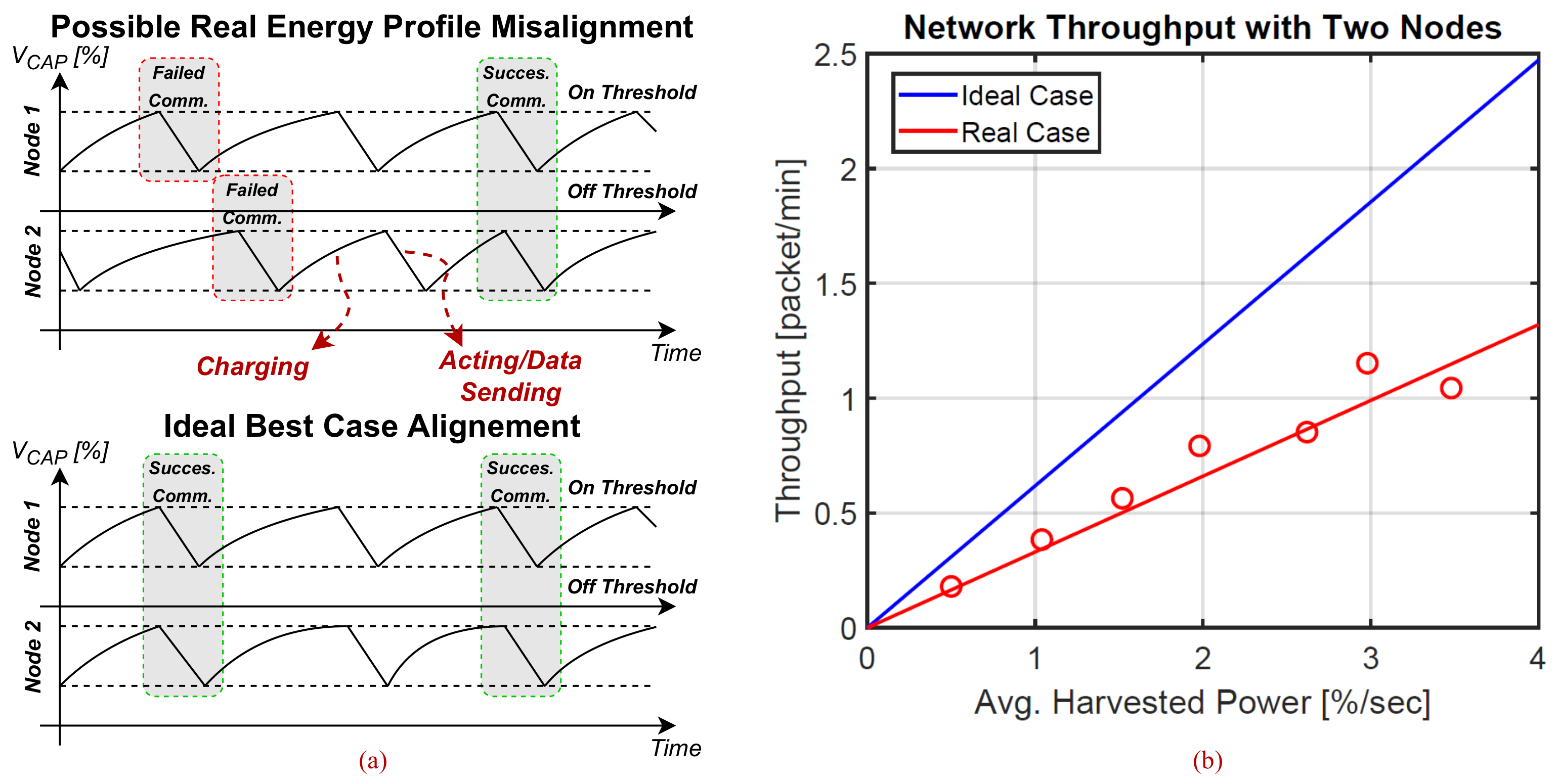
Self-sustainable energy harvesting from the surrounding ambient is challenging since the ambient energy may be random, not constant, and scarce. Ambient energy sources such as solar [2,3], radiofrequency (RF) [4,5], bacteria species [6], vibrations [7,8], turbulent air flows [9], and thermal gradients [10] can provide time-varying–low powered features. Energy-harvesting devices feature small temporary energy storage abilities in capacitors and super-capacitors. The stored limited energy serves relatively energy-demanding operations in combination with low power input from the environment. When the stored energy reaches a certain upper threshold, operations (e.g., sensing, processing, and sending data) can start and proceed until the energy is consumed below a lower threshold. Figure 1a depicts this cyclic operation mechanism by assuming the capacitor voltage VCAP (i.e., a percentage of the maxim capacitor voltage) as a good indicator of the stored energy. When the capacitor drains out, the operation and electronics stop due to a power failure. Therefore, the ordinary life cycle of a batteryless device is composed of charge, action, and die intervals that repeat indefinitely. Therefore, batteryless devices operate intermittently, and only when energy is available can they perform the assigned tasks. The frequency and timing of the power failures depend on the energy availability and application energy requirements. For example, when a node uses a larger photovoltaic cell for energy harvesting [2,3], data collection occurs more frequently. Thus, the more frequently that charge/discharge cycles repeat, the more frequently the nodes can communicate the collected data. In Figure 1b, we also give evidence of a throughput increment related to the average harvested power. As an example of a concrete application, we summarize what Nardello et al. [2] reported to emphasize that the data communication process is one of the most energy-consuming tasks for an IoT batteryless node. Indeed, the capturing, computing, and compressing of a QQVGA image consumes an average of about 5.2 mW for several seconds of MCU intervention, requiring up to 45.9 mJ. The inference processing (i.e., to discern the relevant content of the image before data transmission) takes 4.85 mW for a total of 57.7 mJ. Finally, data communication using LoRa packets with a transmission power of 17 dBm consumes 363.8 mW, requiring up to 78.8 mJ.
Frequent power failures during intermittent operations affect the computation forward progress due to intermittent computing [11] and the reliability of data communication due to intermittent communication [12]. During intermittent computing, devices lose their computational state (e.g., register and memory content) due to frequent power failures. Upon power failures, devices reboot from scratch and need to recover computations from a safe and consistent state. As the harvested energy is very scarce and can even go down to zero, researchers [11,13,14,15] discarded electronics and MCU idle or sleep modes. Indeed, the energy consumed by the electronics in these modalities may be larger than the harvested energy from the ambient, and the node’s supercapacitor may never complete charging. On the other hand, prior works proposed several software-driven techniques (task-based models [11,16] and checkpoints [13,14,17]) for computational state recovery and forward progress of computations. Despite the recent progress in intermittent computing, communication under discontinuous energy (i.e., intermittent communication) is still challenging and mostly overlooked since, in many studies (e.g., [2]), nodes are continuously powered during communication.
1.2. Challenges of Intermittent Communication
Ultra-low-power data exchange is mandatory to achieve communication under strict and limited energy constraints. However, lowering the power consumption per exchanged data packet is not enough to prevent packet losses and related energy waste. While transmitting or receiving, both, the sender and receiver nodes can experience power failures, leading to incomplete and failed communications. We can consider a successful communication attempt only if both sides of the communication channel have sufficient energy to complete the entire process (see Figure 1a). Thus, the sender can engage in energy-reliable communication only if the receiver has enough energy to collect the corresponding packet without power failure. A failed communication attempt leads to energy waste and the need for further communication attempts, having a significant impact on the network performance and lowering the network throughput.
In Figure 1b, we show the network throughput of two generic nodes communicating whenever energy is sufficient to start the data packet transmission. Hence, the energy consumed in the action phase refers only to data packet communication. The Figure reveals how the throughput is affected when the nodes’ energy profiles do not match and power failures occur during data transmission. The red trace represents a possible real case retrieved by experimental results, where the nodes’ energy profiles are random and not perfectly aligned. Thus, data packets are sometimes lost. On the other hand, the blue trace represents a hypothetical scenario where communication happens if nodes have sufficient energy to pursue a transmission–reception task and, in turn, energy profiles are mostly aligned. We report the result as a function of the average harvested power from the ambient, being one of the most significant parameters involved in the process. As seen in Figure 1a, we expressed the incoming power as a percentage of the storage capacitor’s maximum voltage per second. Further parameters, such as the energy required for transmission and reception per data packet, influence the communication success rate. In the particular case study of Figure 1b (“real case”), the energy required for reception is fixed at about 50–60%, strongly penalizing the throughput.
1.3. Contributions
Intermittent communication introduces a challenging scenario where intermittently-operating batteryless devices should not attempt communication when data packets could be lost due to power failure, which would lead to wasted energy. This article addresses this challenge and presents the fundamental hardware circuitry to enable reliable intermittent communication over wireless batteryless node networks. We emphasize two main mechanisms that ensure energy awareness and reliability: energy status-sharing and synchronized operation. We introduce novel low-power and self-sustainable plug-and-play circuits to support these mechanisms.
The rest of this article is organized as follows. We present prior art on low-power communication technologies, issues on node-to-node communication under intermittent operations, and already-existing solutions in the “Related Works” Section 2. We present our novel design to overcome packet loss and energy waste due to power failures during communications in the “Circuits Supporting Reliable Intermittent Communication” Section 3. Then, we present our results in the “Results” Section 4 before concluding the article with final remarks in the “Conclusion” Section 5.
2. Related Works
IoT devices sense physical changes, such as temperature, humidity [2], pressure, and light, or physical representations, such as images [2] or sound waves, and transmit the collected information to the internet. Many of these devices are tiny and portable platforms; thus, a wireless link provides network access. Different communication standards can be used depending on the application, ranging from Bluetooth, Wi-Fi, or ultra-wideband (UWB) for indoor and short-range communications to long-range (LoRa) for outdoor and long-distance applications. These active radio transceivers usually feature analog RF circuitry: a power amplifier (PA) to boost the RF output power and properly drive the antenna, a low noise amplifier (LNA) to boost the received signal, and an RF mixer composing the modulation stage embedding the information upon the RF carrier. All of these elements significantly increase the power requirements to strengthen the RF signal-to-noise ratio (SNR). In contrast, researchers force IoT devices to operate with lower energy budgets, bringing to the limit batteryless devices that rely on marginal amounts of energy and aim to be self-sustainable sensors. In practical terms, communication plays a major role in the power consumption profile. An example reported by M. Nardello et al. in [2] reveals that the power required to transmit the information using LoRa is two times higher than the average power required by the application to sense and compute the information. Although several active radio protocols achieved excellent results in terms of throughput, energy per packet, and coverage, they still require significant energy budgets to operate [18].
2.1. Ultra Low-Power Communication Techniques
As a challenging aspect, the new RF design attempts to boost the performance of the active radio link by lowering the power requirement. As an orthogonal approach, several applications benefit from passive radio links such, as the radio frequency (RF) backscatter [3,19]. Indeed, new emerging RF technologies allow transmission with quasi-zero energy costs for both the transmitter and receiver. RF backscatter, as an example, provides tag-to-tag communication [20,21] by lowering the power consumption by one order of magnitude.
2.1.1. Radio Frequency Backscatter
Backscatter exploits already-present ambient carrier signals and encodes the information by modulating the carrier reflection. Reflecting the impinging signal also requires several orders of magnitude less power than active radio approaches. There is no need for power-hungry components; signal reflection is achieved in a completely passive manner, bringing quasi-zero-power wireless communication capabilities to batteryless nodes. The radio frequency (RF) backscatter, as an example, benefits from externally provided ambient RF signals (e.g., an RF carrier Wi-Fi or TV signals).
As a passive receiver, RF backscatter bases its working principle on passive component demodulation and a low-frequency analog stage to boost the demodulated signal. The key idea is achieving demodulation without involving active RF power-hungry circuits. For example, the RF backscatter receiver presented in [21] is based on an envelope detector made with a Schottky diode, a capacitor, and a resistor. A low-power analog amplifier boosts the envelope detector voltage before digitization. Finally, an analog comparator with an average threshold or an analog-to-digital converter (ADC) provides the digital output. This signal processing requires several orders of magnitude less energy than an active radio receiver.
The backscatter transmission requires an illuminator providing the RF carrier. As the RF carrier provides energy, this energy can be absorbed or reflected. Electromagnetic field propagates can be modeled as transmission lines through air and power can be absorbed or reflected by the line termination (i.e., the antenna and its load). If the termination line impedance matches the line impedance, the energy is captured by the antenna and converted into a voltage by the antenna load-matching impedance. On the contrary, if the termination impedance is not matched, the line termination reflects the impinging energy. As an example, by short-circuiting the antenna, the reflection is at the maximum.
RF switches can provide matching or mismatching of the line termination. Exploiting the metal-oxide field effect transmissions (MOSFETs) allows for on–off keying (OOK) modulation by switching between the on state (i.e., short circuit) and the off state (matched load). Exploiting a specific integrated circuit, such as a multiplexer, can provide a set of different load impedances and, in the end, different matching levels achieving amplitude shift keying (ASK) modulation. Both active circuits can obtain data reception in the so-called monostatic and bistatic network topology [22], or by a passive receiver enabling ambient backscatter tag-to-tag communication [20,21].
2.1.2. Visible Light Communication (VLC)
VLC is another technology that implements passive receivers [25]. VLC encodes the information into a light carrier, which is still an electromagnetic field carrier with a specific frequency in the visible light range. VLC is more likely suitable for indoor applications where the most used illuminator is a specially designed light bulb. Light bulbs can be made of light-emitting diodes (LEDs). Driving the diode with a modulated signal enables the encoding of the information. The LED’s optical output power is related to the supply current. Indeed, the driving circuit operates by modulating the LED’s current between different levels.
Several passive demodulator components exist for visible light, such as photodiodes or photovoltaic cells. Passive receivers are relatively easy to build and achieve excellent energy harvesting capabilities. However, visible light is everywhere. Especially in the outdoor scenario, the sunlight intensity is not easy to surpass. Thus, VLC applications are mostly oriented toward indoor systems. Some standards already exist, such as Li-Fi, although it is not oriented for batteryless devices. Finally, VLC backscatter exists [26,27]; VLC “backscatters” low power by modifying the reflection property of the specially-designed reflecting surfaces.
2.2. Protocols for Reliable Batteryless Communication
The current state-of-the-art in communication and application beyond batteryless devices overlooked intermittent operation during data transmission with active and passive radios [2,3,19]. For example, by exploiting a star network topology, the central receiver hub can be supported by a continuous energy source that will never experience a power failure. With the recent development of point-to-point ultra-low-power communication, IoT batteryless devices are enabled to transfer information between each other [20,21,28]. Thus, the task schedule must include the onboard energy level and the attempted receiver energy status.
Recent studies presented reliable communication protocols for intermittently operating batteryless devices. Torrisi et al. [12] emphasized the need for the nodes to be aware of the energy status of possible receivers to achieve successful data communication. By exploiting the ultra-low-power communication technologies, a node can inform the neighbor about its energy status with the quasi-zero-energy cost. An energy-aware communication protocol named TRAP [29] takes advantage of the energy status-sharing mechanism and synchronization to provide reliable and secure communication over batteryless devices.
The protocol policy based on this information allows for decision and data packet communication scheduling. A node that wants to transmit data to a neighbor node starts collecting the neighboring energy status information. Upon knowledge of the network node’s energy level, the transmitting node is aware of possible available receivers and can decide to either engage in secure communication with another active node or postpone data sending until the desired neighbor become active.
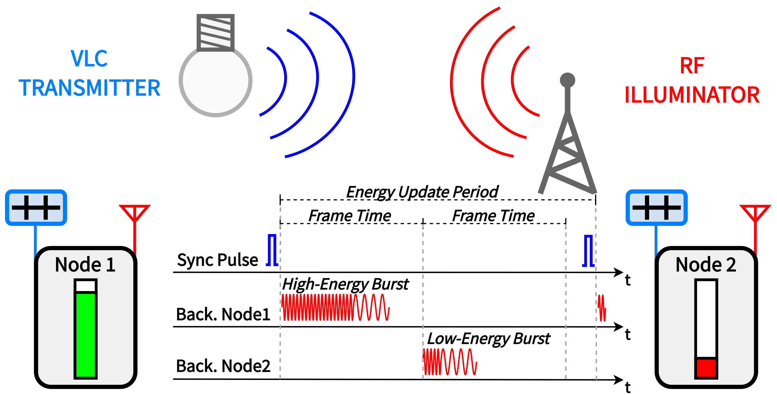
The energy status information is transmitted over the RF backscatter channel as depicted in Figure 2. The modulation scheme comprises different lengths of OOK modulated bursts (i.e., a sequence of on–off pulses). Each length corresponds to a different energy level. In particular, the longer the burst, the higher the energy level. A 32-pulse burst encodes the lowest energy level and the node is completely out of energy. While a 256-pulse burst encodes the highest energy level, and the node is fully charged. The burst duration in the middle indicates that the node is in a charging transient with limited energy availability but can still perform some minor tasks. For example, a 128-pulse burst can encode the availability to engage in a reception task if the energy required for the task is less than the maximum. Furthermore, nodes can identify each other by using different burst modulation frequencies in a range of about 30 kHz. Finally, the burst repetition period determines the update rate of the node’s energy status in the network. A dedicated circuit called the automodulator carries out the encoding energy level encoding process and grants a continuous energy status update over the network.
Moreover, to cover all possible scenarios, the energy status mechanism requires a notion of coordination and synchronization. Indeed, without synchronization, the backscatter channel access is random and determined only by the node’s local time. Due to frequent power failure and low energy constraints, only low-power timekeepers can be used, having relatively low accuracy and potentially high drifts from node to node [30]. To guarantee channel access for all nodes, the energy update period must be much larger than the on-air time of all the nodes. Otherwise, bursts may overlap and collide with each other, causing the energy status update efforts to vanish.
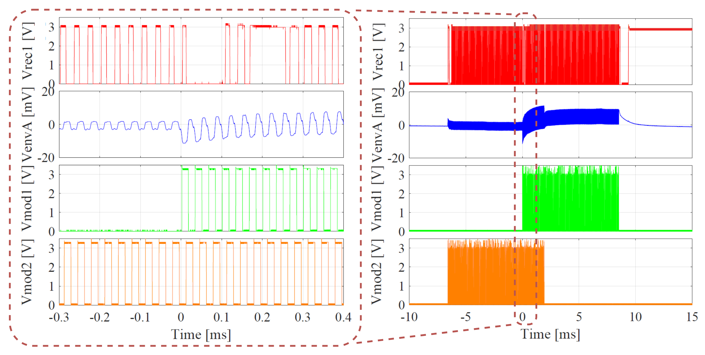
Figure 3 shows a sporadic energy status collision that we captured during a test bed experiment. Two bursts represented by the respective modulation signals VMOD1 on node 1 and VMOD2 on node 2 partially overlap. The overlap interferes with the demodulation process, compromising the envelope detector voltage of the receiver (VENVA). Consequently, the passive backscatter receiver cannot reconstruct the transmitted signal and provide a corrupted digital output (VREC1). Even though this phenomenon is marginal and limited in slow-evolving networks, it can compromise the performance in large or fast-updating networks. Indeed, the collision probability increases when the energy status update period decreases concerning the backscatter on-air time. The protocol covers these events, and when a burst faces interference or becomes corrupt, the node simply skips and waits for the next energy status update.
Other studies have targeted intermittent communication problems. FLYNC [31] proposes maximizing the probability that both sides of the communication channel have sufficient energy to perform a transmission–reception action successfully. FLYNC considers nodes in the same environment and with the same harvesting capability. Thus, energy profiles would be similar. The probability of having both the transmitter and receiver with sufficient energy is augmented by exploiting the synchronization aided by the light flicker of the fluorescent light bulbs. However, data communication is not guaranteed, and a significant amount of packet losses or attempted communications are still present, leading to remarkable energy waste and possible data loss.
Bonito protocol [15] is based on a priori knowledge of the energy harvesting rate distribution and, in turn, the knowledge of the node’s charging time used to synchronize communication actions. Even though Bonito achieved a great success rate (up to 99%) and remarkable throughput enhancement, the data packet exchange is not guaranteed. Furthermore, unlike TRAP, Bonito suffers from a significant overhead of energy and computations required to share the charging time knowledge information over a BLE radio. Significantly, the energy consumption overhead is critical for batteryless applications, which attempt to minimize energy consumption. On the other hand, the latency is clearly minimized in contrast to what we propose and discuss hereinafter.
3. Circuits Supporting Reliable Intermittent Communications
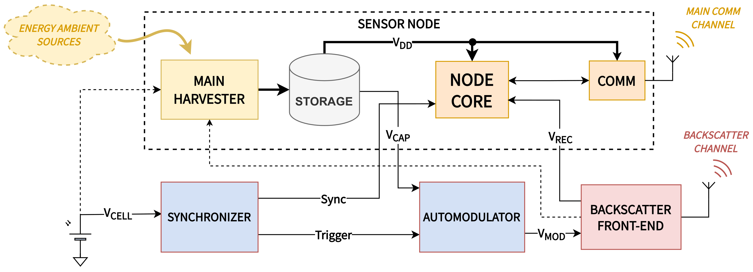
The main challenge is to sense and send the energy status information without impacting the batteryless device’s energy budget. To this end, we designed the “automodulator” circuit to be able to periodically convert the capacitor voltage (a good indicator of the stored energy) into the RF backscatter modulation signal. The key insight is to consume very limited power; thus, we avoided using power-hungry components, such as ADCs and MCUs, and we preferred a digital logic combination circuit. Moreover, the automodulator must provide the energy status signal even in the case of a power failure or low energy availability on the node, providing self-sustainable operations and potentially becoming a plug-and-play solution for all batteryless devices. Finally, to synchronize nodes, we selected VLC, and we designed the “synchronizer” circuit, which triggers the automodulator at a specific time, avoiding the aforementioned issues of burst collision pushing the system to the upper-efficiency limit. These two additional blocks externally surround a possible generic batteryless sensor node as reported by Figure 4.
3.1. Automodulator
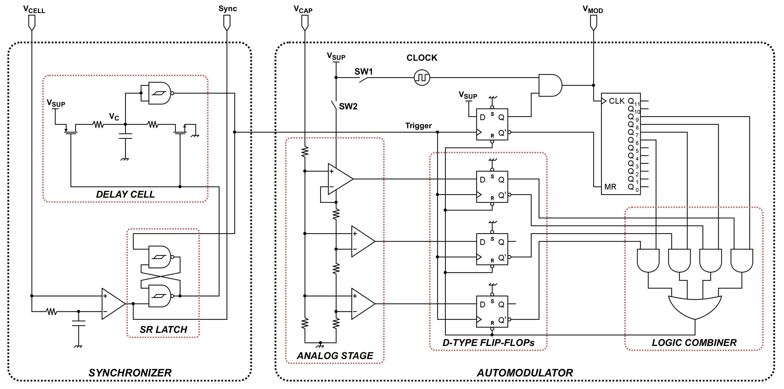
The automodulator is the fundamental building block enabling energy status-sharing. It is directly connected to the storage capacitor to sense the voltage and the RF circuitry to communicate the energy status information over the backscatter channel. Furthermore, it features RF harvesting capabilities on the same RF channel. It mainly consists of three sub-circuits, as reported in Figure 5:
- An analog stage that samples the capacitor voltage through the VCAP signal and discretizes it into four different levels represented by three digital signals;
- A logic combination circuit that uses the information provided by the analog stage and, when triggered, starts producing the modulation signal VMOD for the energy status RF backscatter communication;
- An ultra-low-power and low-frequency oscillator (CLOCK) that provides the modulation frequency upon which the logic combiner constructs the modulation signal.
- Externally, the backscatter front end (visible in Figure 4), which provides access to the RF backscatter channel for the modulation signal and retrieves the neighboring node’s energy status information, providing a digital output VREC used by the node system to enable the protocol operations.
First, the analog stage senses the capacitor voltage using three low-powered analog comparators, one that includes a 1.18 V voltage reference. The capacitor voltage is sensed through a resistive voltage divider with a large value resistor to reduce the current drawn from the capacitor. It is possible to select the proper voltage divider resistor’s value, to tune different voltage thresholds for a specific application. In particular, the threshold design is strongly related to the application, for example, the maximum voltage of the supercapacitor or the threshold related to a specific task energy requirement. Indeed, to design the activation threshold voltage Vth that guarantees a specific task energy requirement Eper-threshold, we must consider the initial storage capacitor voltage, which also coincides with the deactivation threshold Vmin and the storage capacitance, as in the following: . Due to the large value resistor, the comparator input leakage current is also a parameter to consider. Finally, the analog stage output is composed of three digital signals indicating the voltage level as reported in Table 2 divided into three voltage thresholds. More comparators can be used to fine-grain the levels; however, the energy consumption will increase. We built the circuit with COTS analog comparators LTC1540 (with voltage reference) and TLV3691.
Secondly, the automodulator logic combinator mainly works on D-type flip-flops, logic gates, and binary counters. The first set of the three flip-flops samples the digital signals from the analog input side; thus, the energy level is fixed and maintained for all energy status transmission/modulation processes. When the trigger signal sets, the digitized energy level moves from the d-type flip-flop input side to the output side. At the same time, a fourth flip-flop sets and enables the gate to activate the modulation signal VMOD given the modulation clock (CLOCK). The same modulation signal returns to the binary counter, which counts the pulses and activates the outputs accordingly to Table 2. A set of four gates compares the counter outputs with the energy level d-type flip-flop output. As soon as the first logic combination is true, all of the flip-flops reset, the modulation process stops, and the counter clears. The automodulator is ready for a new trigger event.
We built the logic combiner using standard CMOS technology with the CD4040BM96 binary counter, CD4013BE d-type flip-flops, CD4072BE OR gate, and CD4081BE AND gate. We used standard CMOS technology to validate the functionalities of our modules. Thanks to this first implementation, we verified the power requirements and self-sustainable operations, meaning that further circuit refinement, such as a low voltage CMOS (LVCMOS) technology, will be able to sustain autonomous operations. Given the successful results, we will directly move to a VLSI implementation.
We propose providing a modulation clock with a low-frequency, low-power oscillator. A commercial ultra-low power SiT1533AI-H4-DCC-32.768E oscillator was used, providing a frequency of 32.768 kHz for the only modulation. In our original design [29], we benefited from a second ultra-low-power timer, the TPL5111, as a timekeeper to fire a burst transmission every 100 ms. Further improvements can be made by using a zero-power persistent timekeeper [32].
The circuit supply (presented in the circuit diagram of Figure 5 as a signal VSUP) derived by the harvesters takes advantage of the RF ambient [4,24,29] and the ambient light [3,33]. If an energy surplus is available, the harvesters can feed the main storage capacitor. Finally, as one of the main actors in the energy budget (as visible in Table 3), the analog input stage can switch off and turn on by acting on the switch SW1 when a new energy status update is triggered, further saving precious energy. The switch operation requires an additional D-type flip-flop, which sets with the synchronization signal (Sync) to ensure sufficient time for the analog stage to settle and provide the correct output for the logic core. The reset signal is the same as the other four flip-flops in the circuit. Alternatively, the SW1 flip-flop can be reset by considering the output Q of the first flip-flop in the row presented in the circuit diagram, or by acting on the switch SW2, the low-frequency oscillator can switch off if the burst repetition period is extended more than 600 ms. Indeed, the settling time for the selected SiT oscillator is 300 ms.
3.2. Synchronizer
To boost the system communication performance, we introduced a synchronization and time-framing mechanism based on VLC. As previously mentioned, the synchronization avoids the bursts collision and grants time-slotted access to the backscatter for the energy status communication. Even though the synchronizer circuit introduces more complexity, it avoids one of the two local oscillators in the automodulator circuit presented in [29]. Indeed, the synchronizer provides the trigger signal, which fires the automodulator replacing the local timekeeper TPL5111. The benefit of the synchronizer is also evident given the timekeeper’s high startup current (i.e., up to 400 µA).
The synchronizer circuit embeds the hardware to achieve a time-slotted operation for each node given the synchronization signal. Moreover, it can produce more trigger events between two consecutive synchronization events, enabling multiple energy status update cycles.
A dedicated illuminator broadcasts the synchronization light pulse invisible to human eyes. As a VLC receiver, we selected a small-sized photovoltaic cell (46 mm × 15 mm), converting the received light pulse into a voltage pulse Sync. Moreover, the PV can be used as an energy harvester for the whole node, especially for the automodulator circuit.
The VLC passive receiver is based on a low-power average threshold comparator with hysteresis that distinguishes the light pulse from the floor level. The generated sync from the comparator feeds a delay cell, which then provides a fixed time delay according to the node time slot. The time slot duration for each energy status transmission is given by the longest energy status burst plus a 20% guard.
Figure 5 shows details of the delay cell based on an SR latch and an RC network. The two resistors and corresponding MOSFETs provide a charge–discharge path for capacitor C. The charging path involves R1 gives a delay time of . Figure 6 shows how the delay capacitor voltage VC starts increasing after the synchronization pulse until it reaches the upper threshold Vth+ and, consequently, a trigger event is generated. Moreover, as energy is precious, we can exploit the stored capacitor energy and charge to produce a second delay, discharging the capacitor through a second resistor R2. We select the second delay to be equal to the energy status update period given by: . As well, Figure 6 shows that when the decreasing capacitor voltage VC reaches the lower threshold Vth−, a second trigger event is produced.
The selection of the resistor, capacitor, and threshold values follows some design criteria: the larger the capacitance, the higher the delay time and the energy required to charge it. Moreover, an analog comparator is required to accomplish a fine-tuned threshold voltage, which increases the overall power consumption. In our implementation, we used a cheap Schmitt-triggered logic gate CD4093. Assuming the longest burst encoding a high energy status with 256 pulses and a modulation frequency of about 30 kHz, we fixed the frame time to 10 ms. We selected a 10 nF capacitor and multiples of the 1 MΩ resistor to provide the first delay step. Multiple steps were taken by multiplying the resistor value. The energy status update period is given by the frame time multiplied by the number of nodes in the network. We selected a 10 MΩ resistor to achieve an update period of roughly 100 ms.
To conclude, even though we focus on VLC synchronization in this study, the synchronizer can exploit other forms of periodic events or signals, such as signals from wake-up radios. We selected VLC as a feasible indoor already present technology that can also provide a possible massive down-link for large packet updates from the central network hub (such as a secure firmware update for the node MCU).
3.3. Digital Decoding
A passive backscatter receiver [21] grants the backscatter channel access. The receiver front-end demodulates the backscatter signals and generates the bits representing the energy status burst (on the VREC signal).
Decoding of the energy status information shared on the backscatter channel belongs to the data sender node and, in particular, to the node core or MCU. Indeed, a sender node is prone to send data after collecting and computing the surrounding node’s energy status information. The backscatter channel is populated with the energy status, and in the case of synchronization, the VLC provides the start signal for the energy status communication slots. The sender node MCU decodes the energy status-received bursts; in the case of energy availability of the selected sender, it can engage a secure and reliable data transmission. In the case of low energy of the sender or non-necessity of the sender to transmit data, the whole energy status reception process is disabled. Thus, both the backscatter receiver and the MCU interrupts stop further, saving precious energy (i.e., the power consumption of the backscatter receiver front-end is 36 µW).
Thus, the MCU embeds a specific algorithm that runs only in the case of need and includes the following steps:
- First, in the case of VLC synchronization, the trigger signal prompts the MCU to synchronize with the new incoming energy status update cycle;
- The backscatter front-end digital output VREC interrupts the microcontroller and represents the demodulated energy status burst received from a neighbor in the specific time slot;
- The microcontroller accumulates the bits and forms the transmitted energy status burst;
- Considering the duration of the burst, the microcontroller decodes the energy status and, if needed, decides to transmit data to the selected neighbor, avoiding packet losses due to power failures.
Implementing the bare algorithm on an STM32 MCU takes just an additional 76 lines of code and 80 bytes of memory overhead. On the contrary, the implementation of an MSP430 MCU, including a more sophisticated communication stack with the data packet control and FRAM access, takes a total of 759 lines when the application runs with 353 lines. Thus, the protocol and the communication stack require 406 additional lines of code. The memory overhead with the protocol and the communication stack involves extra 2800 bytes when the application requires 2400 bytes. The difference between the two MCU implementations is mostly associated with the communication stack and the library required to have packet control and FRAM access.
4. Results
We built the circuit upon COTS components available on the market and in our laboratory. We measured the power consumption of all the sub-circuits of the automodulator and the synchronizer by using a Keithley 2450 source meter. Table 3 summarizes the values, reporting an overall power requirement of 12.0 µW. The low-frequency oscillator contributes to the major power consumption; thus, in the circuit diagram, we provided control on the supply of this element and the possibility to switch it off (through the SW2 switch) for long energy status update periods. Furthermore, the marginal power required for the system operation of the automodulator and synchronizer is a “third” concerning the power needed to operate the only backscatter passive receiver presented in [21]. We also have the margin to lower the power consumption, for example, by adopting low-voltage CMOS standards or moving to a VLSI implementation [34]. Thus, the energy can be easily harvested by both the RF already present ambient signals [4] or by exploiting the photovoltaic cell [31] depending on the application layer’s convenience.
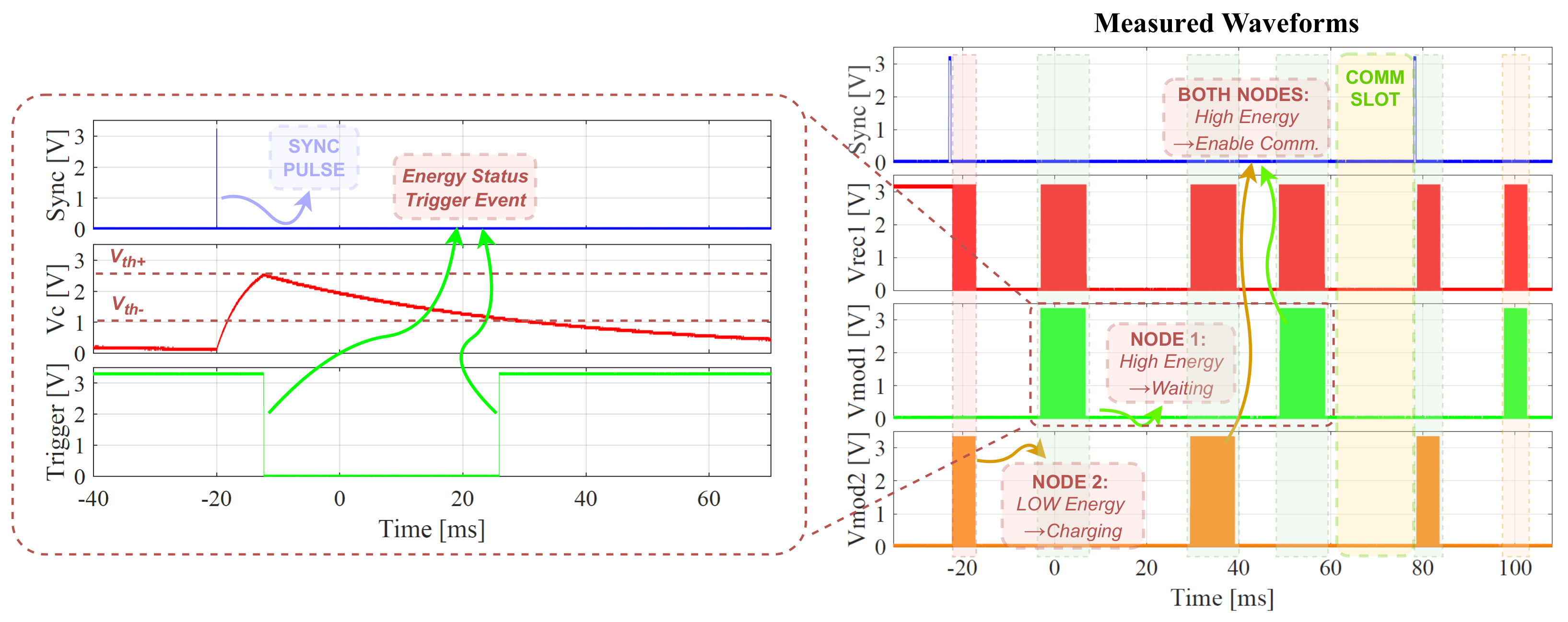
We provided a two-node test bed setup with the same configuration presented in Figure 2; in Figure 7, we measure and highlight the behavior of the hardware layer. We built a “dummy” application using two nodes composed of a charge/discharge cycle where energy is consumed for node-to-node data communication. By exploiting a PicoScope 5442D oscilloscope, we measured the most significant waveforms on the proposed hardware to show a possible real operation scenario. Figure 6 shows the time evolution of the signals on the system:
- The sync signal represents the synchronization pulse given by the analog comparator of node 1. In the specific presented scenario, a synchronization event appears every 100 ms;
- VREC1 represents the received and demodulated bursts shared on the backscatter on the first node;
- VMOD1 represents the modulation signal on node 1. The updated energy status period is set to 50 ms (i.e., two bursts per each synchronization period);
- VMOD2 represents the modulation signal on node 2, the same for node 1;
- VC represents the node 1 synchronizer capacitor voltage responsible for the delay generation after the synchronization event;
- Trigger represents the node 1 trigger signal that fires the automodulator operation with two edges.
The waveforms highlight a possible operation scenario, with the following steps:
- First, a synchronization event is received (Sync pulse) by both nodes and starts the energy status update process.
- On node 1, the synchronizer timing capacitor starts charging (voltage VC increases), and the SR latch produces the first trigger event delayed by roughly 10 ms. Node 1 is fully charged and transmits over the backscatter channel, with a long burst encoding its high energy level, which is visible on the VMOD1.
- The same process takes place for node 2, which is in a charging phase and transmits a medium energy level burst visible on the VMOD2. Thus, no data communication can start between the two nodes.
- The timing capacitor voltage VC decreases, and after roughly 50 ms, a second energy status update is triggered on node 1.
- At that energy update interval, both nodes are at high energy levels and transmit long bursts. Both nodes receive the bursts. This is visible on the VREC1 for node 1.
- After decoding the received energy status, secure data communication can start between the two nodes using the communication slot (which, in a typical application, can be even larger and cover different energy status updates as it uses a different radio).
- After the communication completes, energy is consumed, and both nodes return to low-energy statuses.
To show the benefit of the proposed energy status-sharing mechanism on the sensor network, we ran the same setup with and without using the proposed energy status-sharing mechanism. We compared the network throughput in the two conditions as it is one of the most relevant performance indicators. One great result was the enhanced data packet throughput (more than twice) intended as the number of packets per unit at the time exchanged by the two nodes in the network. Indeed, by using the protocol, no packet is lost due to power failure, and the success rate of the communication attempts is 100%. On the other hand, without the proposed protocol, the throughput is lower, and the communication success rate is 31%, leading to conspicuous energy and data packet losses.
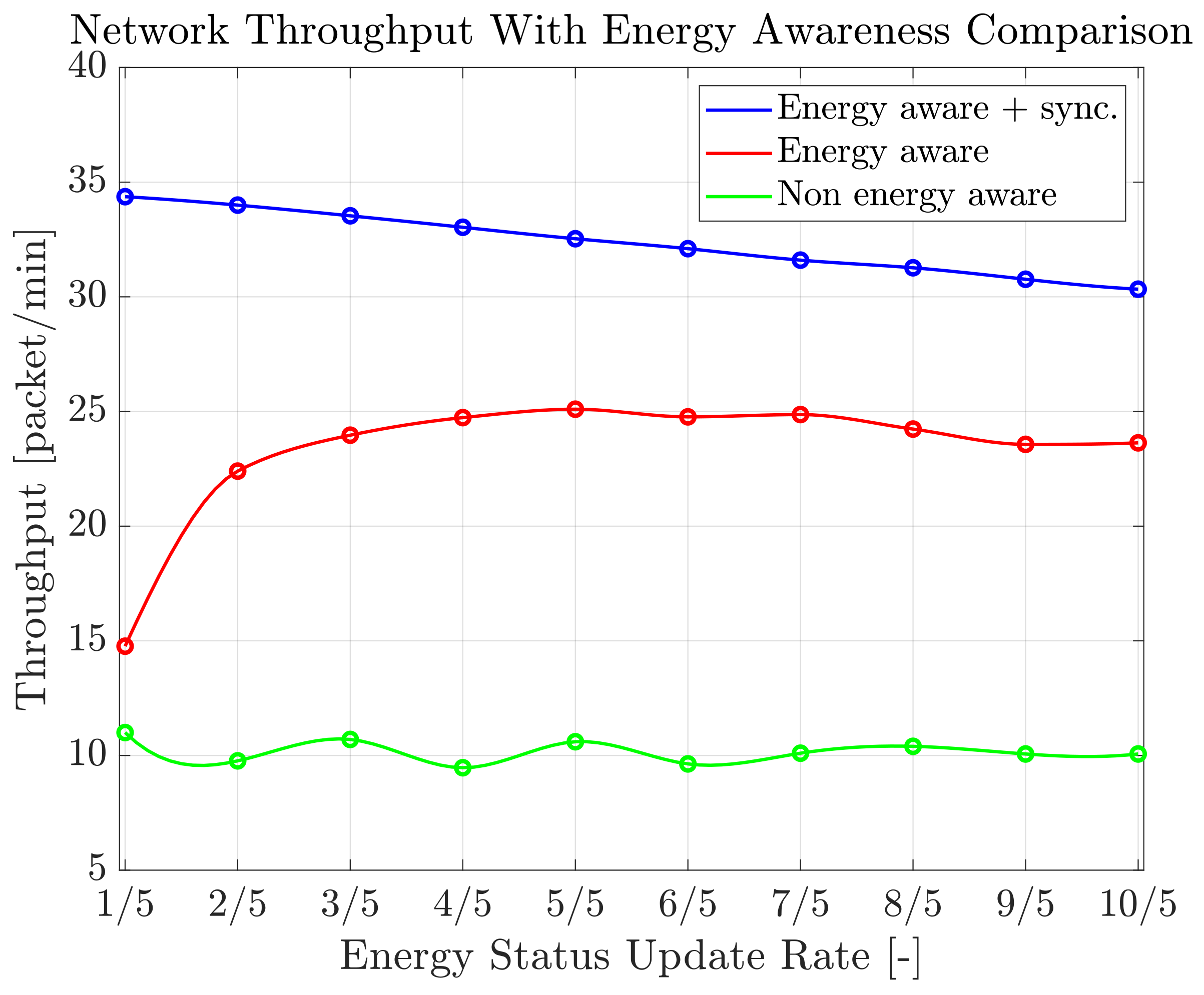
The success rate strongly depends on the test bed and the scenario conditions. Thus, we built a simulator representing the hardware energy status-sharing mechanism to understand the system performance under different scenario conditions. We developed the simulator on Matlab™. It behaves as an event-driven timeline and includes all the hardware aspects, such as backscatter channel occupancy. More details on the simulator can be found in our previous submission [35]. The simulated scenario involves 20 batteryless nodes under various test parameters throughout a 30 min experiment. The test application comprises a charging phase and a single action that repeats indefinitely. During the cycles, the nodes only collect energy from the ambient and consume energy by sending data packets. Thus, all the possible packet losses refer to power failures due to receiving data packets when the node is in a low energy status. Finally, we fixed the average ambient energy harvested by the nodes, and we changed the energy status update period. Figure 8 depicts the network throughput as the number of the overall packets exchanged per unit of time as a function of the relative energy status update rate. The figure compares three different conditions: the system running without an energy-aware protocol, the system running with an energy-aware protocol without synchronization, and the system running with an energy-aware protocol and synchronization. One of the most significant pieces of evidence is that by adopting the proposed hardware-based protocol, the throughput increases, making communications more effective by avoiding data packet loss. Indeed, the throughput in the simulated scenario is more than two times higher than the baseline throughput. For a very high energy status update rate, the throughput decreases due to the increased collision rate of the energy status messages on the backscatter channel, thus reducing the energy update process speed and enlarging the data packet transmission delay. To push the system to the limit, synchronization is mandatory, especially when the update period is very short, and the energy status bursts can collide more frequently. Indeed, by adopting the synchronization mechanism, the throughput increases more than three times concerning the baseline. In particular, with a high energy status update rate, where the lack of synchronization causes the energy status messages to collide with each other, the network performance is higher by more than two times concerning the bare energy aware protocol.
5. Conclusions
In this article, we presented the necessary hardware support for sending the energy status information of batteryless nodes without impacting the energy budget of the devices. We introduced the automodulator circuit that periodically converts the capacitor voltage (i.e., a good indicator of the stored energy) into the RF backscatter modulation signal, which contains information on the energy status. We also presented a VLC-based circuit that synchronizes nodes and triggers the automodulator at a specific time to avoid burst collisions. We built a time-slotted energy status-sharing mechanism where nodes know their neighbor transmission time intervals in advance. We implemented the circuit in a standard CMOS logic and achieved the lowest power consumption of 12 µW. On a test bed setup, we validated the circuit capability. We showed the behavior by reporting the most significant system electric signals. Finally, we showed how the proposed hardware, in combination with a communication protocol, avoids packet loss and achieves superior results in terms of network performance with an almost three times higher throughput. In future work, the natural evolution of the proposed and presented circuit design, which can take part in a VLSI implementation, can be analyzed. Circuit refinement is mandatory to optimize the system functionality. For example, the synchronizer VLC passive receiver can be further optimized for outdoor applications or replaced with a passive wake-up radio that achieves node identification. Furthermore, a dedicated and specially designed two-bit analog-to-digital converter can replace the analog stage that senses the storage capacitor voltage. Finally, additional evaluations of the design will bring improved performance.
Author Contributions
A.T. provided the main contribution on the system design, implementation, and testing together with the manuscript writing. K.S.Y. provided the main contribution to the protocol design together with the manuscript writing. D.B. conceived the concept of Intermittent Communication and related circuits together with K.S.Y., supervised the work and contributed to the manuscript finalization. All authors have read and agreed to the published version of the manuscript.
Funding
This research received no external funding.
Acknowledgments
Authors would like to thank INSTM, National Interuniversity Consortium of Materials Science and Technology for the Ph.D. grant of the first author.
Conflicts of Interest
The authors declare no conflict of interest.
References
- Hester, J.; Sorber, J. The future of sensing is batteryless, intermittent, and awesome. In Proceedings of the 15th ACM Conference on Embedded Network Sensor Systems, Delft, The Netherlands, 6–8 November 2017; pp. 1–6. [Google Scholar]
- Nardello, M.; Desai, H.; Brunelli, D.; Lucia, B. Camaroptera: A batteryless long-range remote visual sensing system. In Proceedings of the 7th International Workshop on Energy Harvesting & Energy-Neutral Sensing Systems, New York, NY, USA, 10 November 2019; pp. 8–14. [Google Scholar]
- Daskalakis, S.N.; Goussetis, G.; Assimonis, S.D.; Tentzeris, M.M.; Georgiadis, A. A uW Backscatter-Morse-Leaf Sensor for Low-Power Agricultural Wireless Sensor Networks. IEEE Sens. J. 2018, 18, 7889–7898. [Google Scholar] [CrossRef] [Green Version]
- Assimonis, S.D.; Daskalakis, S.; Bletsas, A. Sensitive and Efficient RF Harvesting Supply for Batteryless Backscatter Sensor Networks. IEEE Trans. Microw. Theory Tech. 2016, 64, 1327–1338. [Google Scholar] [CrossRef] [Green Version]
- Kwan, J.C.; Fapojuwo, A.O. Sum-Throughput Maximization in Wireless Sensor Networks With Radio Frequency Energy Harvesting and Backscatter Communication. IEEE Sens. J. 2018, 18, 7325–7339. [Google Scholar] [CrossRef]
- Sartori, D.; Brunelli, D. A smart sensor for precision agriculture powered by microbial fuel cells. In Proceedings of the 2016 IEEE Sensors Applications Symposium (SAS), Catania, Italy, 20–22 April 2016; pp. 1–6. [Google Scholar] [CrossRef]
- Muscat, A.; Bhattacharya, S.; Zhu, Y. Electromagnetic Vibrational Energy Harvesters: A Review. Sensors 2022, 22, 5555. [Google Scholar] [CrossRef] [PubMed]
- Covaci, C.; Gontean, A. Piezoelectric Energy Harvesting Solutions: A Review. Sensors 2020, 20, 3512. [Google Scholar] [CrossRef] [PubMed]
- Demori, M.; Ferrari, M.; Bonzanini, A.; Poesio, P.; Ferrari, V. Autonomous Sensors Powered by Energy Harvesting from von Karman Vortices in Airflow. Sensors 2017, 17, 2100. [Google Scholar] [CrossRef] [PubMed] [Green Version]
- Kishore, R.A.; Priya, S. A Review on Low-Grade Thermal Energy Harvesting: Materials, Methods and Devices. Materials 2018, 11, 1433. [Google Scholar] [CrossRef] [PubMed] [Green Version]
- Colin, A.; Lucia, B. Chain: Tasks and channels for reliable intermittent programs. In Proceedings of the 2016 ACM SIGPLAN International Conference on Object-Oriented Programming, Systems, Languages, and Applications, Amsterdam, The Netherlands, 2–4 November 2016; pp. 514–530. [Google Scholar]
- Torrisi, A.; Brunelli, D.; Yildirim, K.S. Zero Power Energy-Aware Communication for Transiently-Powered Sensing Systems. In Proceedings of the 8th International Workshop on Energy Harvesting and Energy-Neutral Sensing Systems, Virtual Event, 16–19 November 2020; pp. 43–49. [Google Scholar]
- Rodriguez Arreola, A.; Balsamo, D.; Merrett, G.V.; Weddell, A.S. RESTOP: Retaining External Peripheral State in Intermittently-Powered Sensor Systems. Sensors 2018, 18, 172. [Google Scholar] [CrossRef] [PubMed] [Green Version]
- Yıldız, E.; Chen, L.; Yıldırım, K.S. Immortal Threads: Multithreaded Event-driven Intermittent Computing on Ultra-Low-Power Microcontrollers. In Proceedings of the 16th USENIX Symposium on Operating Systems Design and Implementation (OSDI 22), Carlsbad, CA, USA, 11–13 July 2022; pp. 339–355. [Google Scholar]
- Geissdoerfer, K.; Zimmerling, M. Learning to Communicate Effectively Between Battery-free Devices. In Proceedings of the 19th USENIX Symposium on Networked Systems Design and Implementation (NSDI 22), Renton, WA, USA, 4–6 April 2022; pp. 419–435. [Google Scholar]
- Yıldırım, K.S.; Majid, A.Y.; Patoukas, D.; Schaper, K.; Pawelczak, P.; Hester, J. Ink: Reactive kernel for tiny batteryless sensors. In Proceedings of the 16th ACM Conference on Embedded Networked Sensor Systems, Shenzhen, China, 4–7 November 2018; pp. 41–53. [Google Scholar]
- Balsamo, D.; Weddell, A.S.; Das, A.; Arreola, A.R.; Brunelli, D.; Al-Hashimi, B.M.; Merrett, G.V.; Benini, L. Hibernus++: A self-calibrating and adaptive system for transiently-powered embedded devices. IEEE Trans. Comput.-Aided Des. Integr. Circuits Syst. 2016, 35, 1968–1980. [Google Scholar] [CrossRef]
- Ryoo, J.; Karimi, Y.; Athalye, A.; Stanaćević, M.; Das, S.R.; Djurić, P. Barnet: Towards activity recognition using passive backscattering tag-to-tag network. In Proceedings of the 16th Annual International Conference on Mobile Systems, Applications, and Services, Munich Germany, 10–15 June 2018; pp. 414–427. [Google Scholar]
- Kantareddy, S.N.R.; Mathews, I.; Sun, S.; Layurova, M.; Thapa, J.; Correa-Baena, J.P.; Bhattacharyya, R.; Buonassisi, T.; Sarma, S.E.; Peters, I.M. Perovskite PV-Powered RFID: Enabling Low-Cost Self-Powered IoT Sensors. IEEE Sens. J. 2020, 20, 471–478. [Google Scholar] [CrossRef] [Green Version]
- Ryoo, J.; Jian, J.; Athalye, A.; Das, S.R.; Stanaćević, M. Design and Evaluation of “BTTN”: A Backscattering Tag-to-Tag Network. IEEE Internet Things J. 2018, 5, 2844–2855. [Google Scholar] [CrossRef]
- Majid, A.Y.; Jansen, M.; Delgado, G.O.; Yildirim, K.S.; Pawełłzak, P. Multi-hop backscatter tag-to-tag networks. In Proceedings of the IEEE INFOCOM 2019-IEEE Conference on Computer Communications, Paris, France, 29 April–2 May 2019; pp. 721–729. [Google Scholar]
- Talla, V.; Smith, J.; Gollakota, S. Advances and Open Problems in Backscatter Networking. Getmobile Mob. Comput. Commun. 2021, 24, 32–38. [Google Scholar] [CrossRef]
- Colaiuda, D.; Ulisse, I.; Ferri, G. Rectifiers’ Design and Optimization for a Dual-Channel RF Energy Harvester. J. Low Power Electron. Appl. 2020, 10, 11. [Google Scholar] [CrossRef] [Green Version]
- Li, D. Backscatter Communication via Harvest-Then-Transmit Relaying. IEEE Trans. Veh. Technol. 2020, 69, 6843–6847. [Google Scholar] [CrossRef]
- Rehman, S.U.; Ullah, S.; Chong, P.H.J.; Yongchareon, S.; Komosny, D. Visible light communication: A system perspective—Overview and challenges. Sensors 2019, 19, 1153. [Google Scholar] [CrossRef] [PubMed] [Green Version]
- Xu, X.; Shen, Y.; Yang, J.; Xu, C.; Shen, G.; Chen, G.; Ni, Y. PassiveVLC: Enabling Practical Visible Light Backscatter Communication for Battery-Free IoT Applications. In Proceedings of the 23rd Annual International Conference on Mobile Computing and Networking, MobiCom ’17, Snowbird, UT, USA, 16–17 October 2017; Association for Computing Machinery: New York, NY, USA, 2017; pp. 180–192. [Google Scholar] [CrossRef]
- Shao, S.; Khreishah, A.; Elgala, H. Pixelated VLC-Backscattering for Self-Charging Indoor IoT Devices. IEEE Photonics Technol. Lett. 2017, 29, 177–180. [Google Scholar] [CrossRef] [Green Version]
- Duan, R.; Wang, X.; Yigitler, H.; Sheikh, M.U.; Jantti, R.; Han, Z. Ambient Backscatter Communications for Future Ultra-Low-Power Machine Type Communications: Challenges, Solutions, Opportunities, and Future Research Trends. IEEE Commun. Mag. 2020, 58, 42–47. [Google Scholar] [CrossRef]
- Torrisi, A.; Yıldırım, K.S.; Brunelli, D. Reliable Transiently-Powered Communication. IEEE Sens. J. 2022, 22, 9124–9134. [Google Scholar] [CrossRef]
- Hester, J.; Tobias, N.; Rahmati, A.; Sitanayah, L.; Holcomb, D.; Fu, K.; Burleson, W.P.; Sorber, J. Persistent Clocks for Batteryless Sensing Devices. ACM Trans. Embed. Comput. Syst. 2016, 15, 77. [Google Scholar] [CrossRef]
- Geissdoerfer, K.; Zimmerling, M. Bootstrapping Battery-free Wireless Networks: Efficient Neighbor Discovery and Synchronization in the Face of Intermittency. In Proceedings of the 18th USENIX Symposium on Networked Systems Design and Implementation (NSDI 2021), Virtual Event, 12–14 April 2021; pp. 439–455. [Google Scholar]
- De Winkel, J.; Delle Donne, C.; Yildirim, K.S.; Pawełczak, P.; Hester, J. Reliable Timekeeping for Intermittent Computing. In Proceedings of the Twenty-Fifth International Conference on Architectural Support for Programming Languages and Operating Systems, Lausanne, Switzerland, 16–20 March 2020; pp. 53–67. [Google Scholar]
- Mir, M.S.; Guzman, B.G.; Varshney, A.; Giustiniano, D. PassiveLiFi: Rethinking LiFi for Low-Power and Long Range RF Backscatter. In Proceedings of the 27th Annual International Conference on Mobile Computing and Networking, MobiCom ’21, New Orleans, LA, USA, 25–29 October 2021; Association for Computing Machinery: New York, NY, USA, 2021; pp. 697–709. [Google Scholar] [CrossRef]
- Kim, G.; Lee, Y.; Bang, S.; Lee, I.; Kim, Y.; Sylvester, D.; Blaauw, D. A 695 pW standby power optical wake-up receiver for wireless sensor nodes. In Proceedings of the IEEE 2012 Custom Integrated Circuits Conference, San Jose, CA, USA, 9–12 September 2012; pp. 1–4. [Google Scholar]
- Torrisi, A.; Yıldırım, K.S.; Brunelli, D. Visible Light Synchronization for Time-Slotted Energy-Aware Transiently-Powered Communication. In Proceedings of the 2022 IEEE/ACM International Symposium on Low Power Electronics and Design (ISLPED), Boston, MA, USA, 1–3 August 2022. [Google Scholar]
Figure 1.
Common energy profile for an IoT batteryless node application (a). Evidence of the cyclic repetition of the charge/discharge phases. Two energy profiles can include sense–compute–send actions. When nodes enter the data-sending mode, transmission can fail due to the energy unavailability of the receiver affecting the network performance. The graph in figure (b) shows the ideal limit case, where the nodes consume all the energy for successful data transmission, with respect to a real experimental case study, where packet loss due to power failure reduces the throughput.

Figure 2.
Representation of the two-node communication scenario. In particular, two nodes equipped with the proposed hardware exchange the energy status information over the RF backscatter channel in a synchronized time-slotted approach. The RF backscatter and VLC synchronization are supported by an external infrastructure composed of an RF illuminator and a VLC transmitter (i.e., a light bulb).

Figure 3.
Burst collision representation from a real test bed experiment. Two transmitted bursts represented by the modulation signals VMOD1 and VMOD2 collide with each other. As a consequence, the receiver envelope detector voltage VENVA is corrupted, and the digital output signal VREC1 glitches.
Figure 3.
Burst collision representation from a real test bed experiment. Two transmitted bursts represented by the modulation signals VMOD1 and VMOD2 collide with each other. As a consequence, the receiver envelope detector voltage VENVA is corrupted, and the digital output signal VREC1 glitches.

Figure 4.
System block diagram comprising the general elements of a batteryless sensor node and the additional synchronizer, automodulator, and backscatter front-end required for the energy status-sharing mechanism.
Figure 4.
System block diagram comprising the general elements of a batteryless sensor node and the additional synchronizer, automodulator, and backscatter front-end required for the energy status-sharing mechanism.

Figure 5.
Circuit diagram, including the automodulator and the synchronizer. The circuit takes as input the photovoltaic cell voltage VCELL as a synchronization signal, the node’s supercapacitor voltage VCAP, and produces the modulation signal VMOD for the backscatter front-end.
Figure 5.
Circuit diagram, including the automodulator and the synchronizer. The circuit takes as input the photovoltaic cell voltage VCELL as a synchronization signal, the node’s supercapacitor voltage VCAP, and produces the modulation signal VMOD for the backscatter front-end.

Figure 6.
System signals measured during a real two-node communication scenario. The VMOD1 and VMOD2 represent the energy status modulation signals provided by the automodulator of the two nodes. VREC1 and Sync represent, respectively, the received energy status and the synchronization signal on node 1.

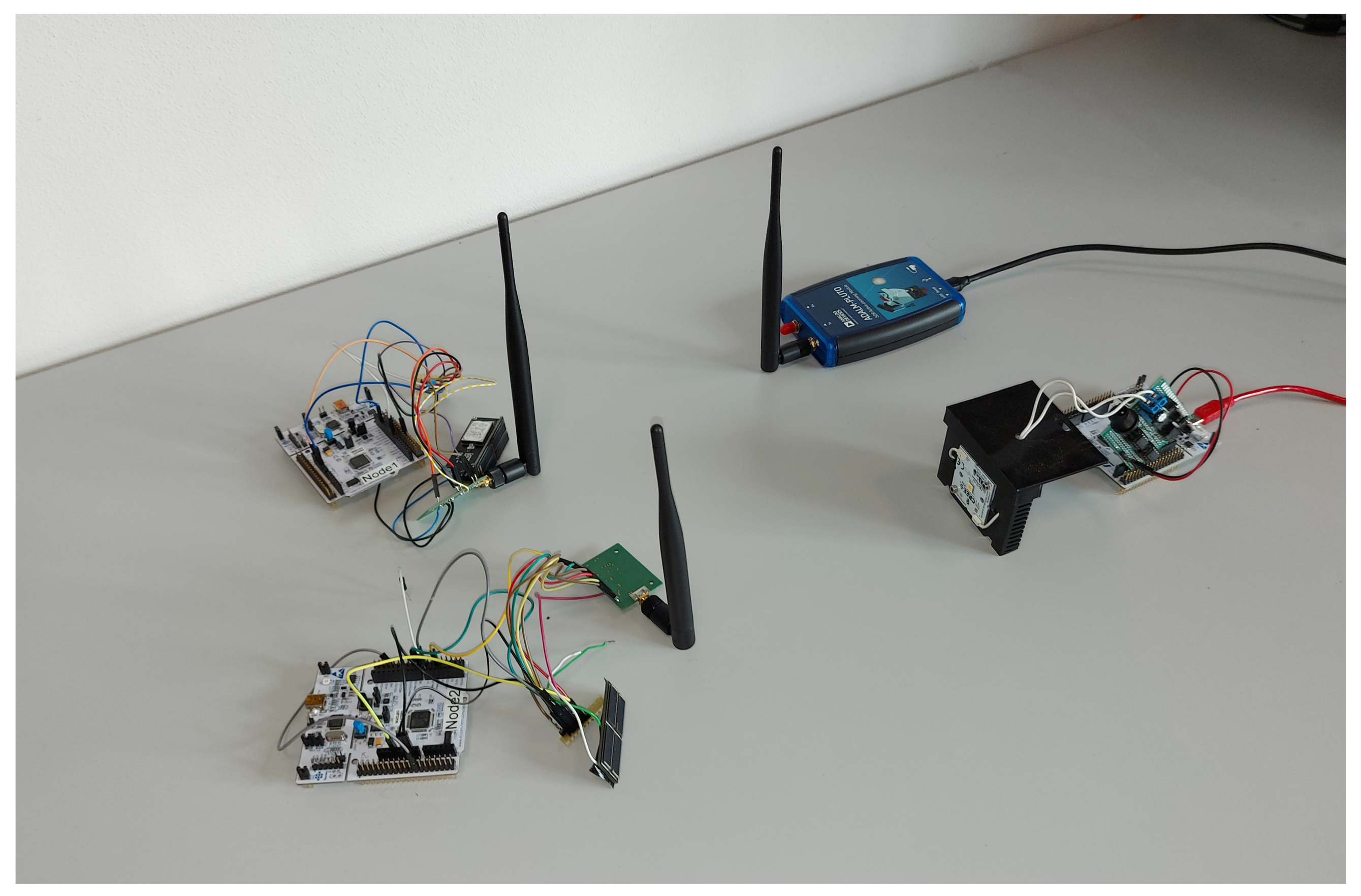
Figure 7.
Photo of the two-node test bed setup. Evidence of the RF illuminator (ADALM-PLUTO), the VLC transmitter (STM32 Nucleo plus an LED driver), the two nodes with the respective antenna and PV cell, and the MCU board.
Figure 7.
Photo of the two-node test bed setup. Evidence of the RF illuminator (ADALM-PLUTO), the VLC transmitter (STM32 Nucleo plus an LED driver), the two nodes with the respective antenna and PV cell, and the MCU board.

Figure 8.
Network throughput as a function of the relative energy status update rate. A comparison of three different conditions: network without any energy-aware protocol (green trace), network with the proposed hardware-based energy-aware protocol without synchronization (red trace), and with synchronization (blue trace).


Table 1.
Battery-powered versus batteryless: a comparison of the pros and cons.
| Battery-Powered | Batteryless |
|---|---|
| Relatively high maintenance costs | Quasi-zero maintenance costs |
| High disposal costs | Low disposal costs |
| Relatively large weight and dimensions | Drastically reduced weight and dimensions |
| Well-known energy budget | Limited and not constant energy budget |
| Continuous operations | Intermittent operations |
Table 2.
Threshold and energy levels.
| Energy Level | Burst Pulses Length | Th 1 -2 -3 | Counter Outputs |
|---|---|---|---|
| Lowest | 32 | 0-0-0 | Q6 |
| Mid-low | 64 | 1-0-0 | Q6-Q7 |
| Mid-high | 128 | 1-1-0 | Q6-Q7-Q8 |
| Highest | 256 | 1-1-1 | Q6-Q7-Q8-Q9 |
Table 3.
Power consumption profile with a 3.3 V supply, including the synchronizer and automodulator.
Table 3.
Power consumption profile with a 3.3 V supply, including the synchronizer and automodulator.
| Block | Current [µA] | Power [µW] | |
|---|---|---|---|
| Automodulator | Logic core | 0.39 | 1.29 |
| Low-frequency oscillator | 2.06 | 6.80 | |
| Analog stage | 0.48 | 1.58 | |
| Capacitor sense current | 0.25 | 0.83 | |
| Synchronizer | Delay cell | 0.45 | 1.5 |
| Overall | 3.63 | 12.0 |
Publisher’s Note: MDPI stays neutral with regard to jurisdictional claims in published maps and institutional affiliations. |
© 2022 by the authors. Licensee MDPI, Basel, Switzerland. This article is an open access article distributed under the terms and conditions of the Creative Commons Attribution (CC BY) license (https://creativecommons.org/licenses/by/4.0/).
Share and Cite
MDPI and ACS Style
Torrisi, A.; Yıldırım, K.S.; Brunelli, D. Ultra-Low-Power Circuits for Intermittent Communication. J. Low Power Electron. Appl. 2022, 12, 60. https://doi.org/10.3390/jlpea12040060
AMA Style
Torrisi A, Yıldırım KS, Brunelli D. Ultra-Low-Power Circuits for Intermittent Communication. Journal of Low Power Electronics and Applications. 2022; 12(4):60. https://doi.org/10.3390/jlpea12040060
Chicago/Turabian StyleTorrisi, Alessandro, Kasım Sinan Yıldırım, and Davide Brunelli. 2022. "Ultra-Low-Power Circuits for Intermittent Communication" Journal of Low Power Electronics and Applications 12, no. 4: 60. https://doi.org/10.3390/jlpea12040060
Note that from the first issue of 2016, this journal uses article numbers instead of page numbers. See further details here.