1. Introduction
Ground source heat pump (GSHP) systems have been proven to have higher efficiency compared to conventional air source heat pump (ASHP) systems for space heating and cooling applications. This is due to the relatively stable subterranean temperature in which GSHP systems exploit to extract and reject heat, whereas ASHP systems are exposed to large fluctuation in ambient temperature and climate conditions. GSHP installations do not require large cooling towers, or can be coupled with one for greater efficiency. Hence, their running costs are lower than ASHP systems. Garber
et al. [
1] suggest that potential savings from a GSHP system largely depend on projected HVAC system efficiencies and gas and electricity prices. The risk analysis performed shows that a full-size GSHP with auxiliary back up is potentially the most economical system configuration.
The thermal performance of GSHP depends on many parameters such as short-term weather variations, seasonal variations, moisture content of soil, and thermal conductivity of soil among others that would affect the temperature of ground [
2]. GSHP systems extract and reject heat by means of ground heat exchangers (GHE). GHE can be generally classified into two widely installed closed-loop types, which are vertical and horizontal configurations. Vertical GHE are pipes installed vertically in boreholes typically 15–120 m deep. Meanwhile, pipes are laid and buried in trenches 1–2 m deep in horizontal ground heat exchangers (HGHE) installations. Vertical GHE, commonly installed where availability of land area is scarce, provides high and steady thermal performance as less temperature fluctuation occurs along with depth. Moister soil and possible underground water flow in deep region would also contribute to higher heat exchange rate.
While vertical GHE are favorable, this type of installation may hinder small and medium enterprises and homeowners due to high capital costs involved. Furthermore, only specialized contractors are well-equipped in terms of equipment and skills for borehole drilling operations. On the other hand, the installations of HGHE are relatively cost-effective operation and rather straightforward which mainly involve excavation of shallow trenches. HGHE installations would be convenient where land area is abundant. The drawback of such shallow installations is that it is prone to unstable thermal performance due to temporal weathers and seasonal variations. Pulat
et al. [
3] performed economic analysis by comparing experimentally GSHP system using HGHE to conventional heating methods and it was shown that the GSHP system is more cost effective than all other conventional heating systems. Naili
et al. [
4] conducted in-field analysis that showed the utilization of HGHE is appropriate for cooling building in Tunisia, which is characterized by a hot climate.
Numerical modeling has been used in many studies to accurately predict the thermal performance of GHE. This is useful in achieving optimum design and economic feasibility before the commissioning of GSHP systems. Nam
et al. [
5] developed a numerical model that combines a heat transport model with ground water flow for vertical GHE and was validated with experimental results. The heat transfer rate for an actual office building operation in Tokyo, Japan was predicted using this model. Jalaluddin and Miyara [
6,
7] investigated the thermal performances of vertical GHE under different operation mode including discontinuous 2 h operation in cooling mode and alternative operation mode between cooling and heating process to provide hot water supply. Discontinuous and alternative operation modes help to alleviate the heat buildup around the borehole thus increasing the heat exchange rate.
The operation of HGHE has been studied in several research papers. Flaga-Maryanczyk
et al. [
8] presented comparable results between experimental measurements and numerical simulation of HGHE operation at a cold climate for a passive house ventilation system. CFD simulation performed by Tarnawski
et al. [
9] shows that straight HGHE in GSHP system offers relatively low thermal degradation of the ground environment, lower cost of heating and cooling, and higher operating efficiency than electric resistance heating or ASHP system. Energy consumptions in the GSHP system is primarily contributed by heat pump unit
i.e., compressor and fan compared to the small requirement to drive the circulation pump for HGHE.
Benazza
et al. [
10] studied HGHE that were laid out concentrically for cooling purposes in continuous and cyclic operating mode by modeling the air and ground temperature using a simple harmonic function. It was reported that the cyclic operation allows a certain thermal discharge during the shut-up period providing an increase of the heat exchange rate compared to continuous operation.
Rezaei-Bazkiaei
et al. [
11] suggest that by backfilling HGHE trenches with an intermediate layer of material having different thermal characteristics have the potential to enhance heat exchange rate. An aggregate made from recycled tire acted as insulating layer in cold climate areas thus enhancing heat extraction and a high conductive intermediate layer of saturated sand helped to dissipate heat during cooling operation. Simms
et al. [
12] examined the performance of HGHE in soil with heterogeneous thermal conductivity. The analysis supports the assumption of homogeneity when modeling and designing HGHE as the effect of heterogeneity was found to be minimal relative to uncertainty of the mean soil thermal conductivity. Soil continuum was used to examine heat transfer interference between adjacent pipes, which may reduce the thermal performance of the system.
Recent studies show that spiral or slinky pipes are increasingly gaining attention compared to conventional straight polyethylene pipes as greater pipe length per trench length can be achieved thus increasing surface area for heat transfer. Li
et al. [
13] adapted moving ring source model to solve analytically the temperature response of a spiral heat exchanger with groundwater flow. The effects of different water velocities on soil temperature variation during the operation of a spiral heater with different water velocities were studied experimentally. Wu
et al. [
14] compared the thermal performance between straight and slinky HGHE operation. The specific heat extraction rate for both the straight and slinky GHE operation was comparable initially but the performance decreasing along with operating time at different rates. Although the heat extraction rate per pipe length of the straight HGHE would be higher than that of the slinky HGHE loops, the heat extraction per trench length of the latter was significantly higher than that of the former.
Congedo
et al. [
15] reported that slinky HGHE loops configuration provides greater heat exchange area compared to straight pipes. This presents an opportunity in optimizing HGHE design by allowing the length of pipes and trench excavation work hence the required land area to be reduced. Their analysis covered for system operation in both summer and winter. It was determined that the thermal conductivity of the ground and the velocity of working fluid inside the HGHE are the key factors that affect the heat exchange rate. Fujii
et al. [
16] performed numerical modeling of slinky HGHE loops operation by using time-varying parameter,
i.e., ground heat flux as surface boundary condition to improve the analysis accuracy. In their model, the geometry of the HGHE was simplified to a thin plate. The simulation results were found agreeable with the experimental thermal response tests and long-term air-conditioning tests.
Chong
et al. [
17] investigated the effect of loop pitch and loop diameter on the thermal performance of slinky HGHE loops. A cost-benefit analysis was presented to evaluate the effect of the required amount of pipe material and excavation costs on thermal performance. The analysis indicates that a maximum increase about 16% in heat exchange rate is attainable using smaller loop pitch compared to larger loop pitch configurations, as a result of increased heat transfer area per trench length. Although the excavation work required in installing smaller loop pitch is reduced, the material cost is significantly increased, close to twofold. It is also worth noting that the effect of loop diameter on thermal performance is to a lesser extent compared to the change in loop pitch.
In this work, the numerical modeling of slinky HGHE loops in several operations was simulated by incorporating time- and position-varying parameters, which would provide a realistic condition. The simulation includes short time period of operation of exact shape of single and parallel HGHE loops. The effect of different pipe material, parallel operation and spacing between adjacent parallel loops on heat exchange rate are also discussed.
3. Results and Discussion
The thermal performance of HGHE was assessed by the heat exchange rate at the interface between the pipe surface and surrounding ground. The total surface heat flux along the pipe,
q were obtained from CFD solution. The heat exchange rate expressed in per unit pipe length,
is calculated using Equation (3) for single loop and
using Equation (4) for parallel loops.
where
qi is the total surface heat flux along pipe
i,
A is the surface area along the pipe, which equals 0.63 m
2, and
L is the pipe length which equals 4.24 m.
3.1. Continuous 24 h Operation
In this work, continuous cooling operation was investigated similar to the method in conducting thermal response test for borehole with the exception the inlet temperature was set constant.
Table 2 summarizes the mean heat exchange rate for continuous 24 h operations. The results for parallel loops operation is discussed in
Section 3.4.
Table 2.
Summary of mean heat exchange rate in continuous 24 h operation in cooling mode.
Table 2.
Summary of mean heat exchange rate in continuous 24 h operation in cooling mode.
| Operation | Material | Orientation | Spacing Between Adjacent Loops (m) | Heat Exchange Rate at 24 h (W/m) | Mean Heat Exchange Rate (W/m) |
|---|
| Single loop | HDPE | Horizontal | – | 29.6 | 38.8 |
| HDPE | Vertical | – | 29.8 | 39.1 |
| Copper | Horizontal | – | 33.5 | 57.5 |
| Double loops | HDPE | Horizontal | 0 m | 54.2 | 71.8 |
| HDPE | Horizontal | 0.5 m | 58.8 | 82.1 |
| HDPE | Horizontal | 1.0 m | 59.8 | 82.5 |
| HDPE | Horizontal | 2.0 m | 58.9 | 82.1 |
| HDPE | Horizontal | 4.0 m | 58.9 | 82.1 |
| Triple loops | HDPE | Horizontal | 0 m | 77.5 | 101.7 |
| HDPE | Horizontal | 0.5 m | 86.5 | 114.1 |
| HDPE | Horizontal | 1.0 m | 86.6 | 114.2 |
| HDPE | Horizontal | 2.0 m | 88.5 | 115.4 |
| HDPE | Horizontal | 4.0 m | 86.8 | 114.5 |
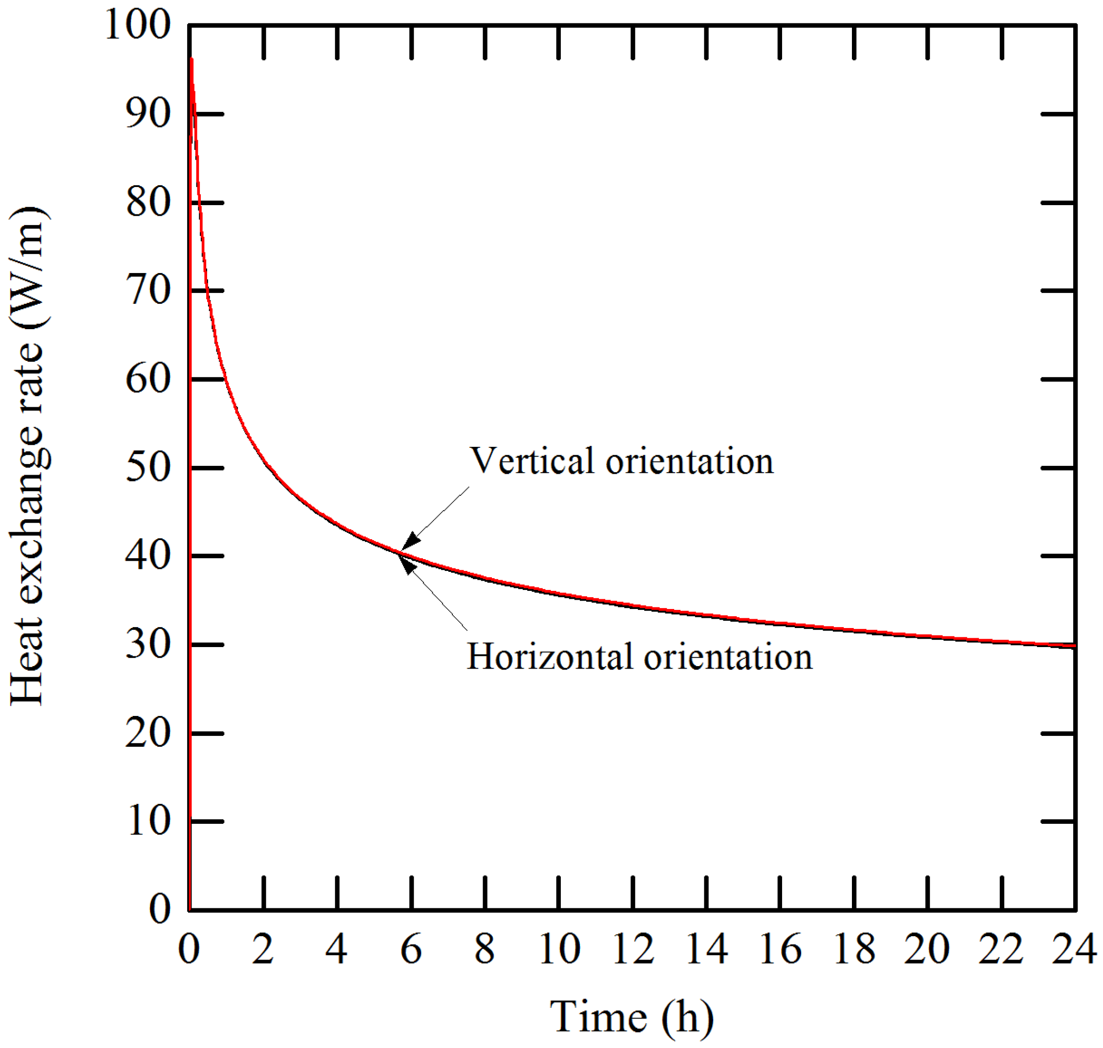
Figure 5 shows comparisons between the orientations of HGHE on heat exchange rate during 24 h operation period. The heat exchange rate in horizontal and vertical orientations was comparable with the latter slightly higher than the former. Generally, the heat exchange rate peaks within the first 5 min of operation before having a steep decrease until 4 h of operation as the ground warms up. Subsequently the heat exchange rate continues to decrease in a lesser degree until the operation ends as energy is dissipated throughout the ground. The mean heat exchange rate for vertical orientation is only 0.8% higher compared to that in horizontal orientation. Correspondingly, at the end of 24 h of operation, the heat exchange rate for vertical orientation is slightly (0.7%) higher compared to that in horizontal orientation. The effect of HGHE orientation on thermal performance is insignificant although the trench depth increases by one third. Burying the HGHE in vertical orientation means extra trenching work is required and this adds to the installation cost. On the other hand, HGHE in horizontal orientation are easier to install. Vertical orientation is suggested in installation where land area is limited. Further analysis of HGHE operation beyond this point was investigated in horizontal orientation.
Figure 5.
The effect of different orientations on heat exchange rate.
Figure 5.
The effect of different orientations on heat exchange rate.
The effect of different pipe material on heat exchange rate was investigated and compared as shown in
Figure 6. It can be observed that for copper loop, the heat exchange rate peaks to over 150 W/m compared to that in HDPE loop at 95 W/m during the early operation period. Soon afterward, the heat exchange rate decreases in a much rapid manner. This might be because high temperature gradient presence in copper loop wall as opposed to low temperature gradient in HDPE loop wall. After 1 h of operation, the heat exchange rate begins to gradually decrease as the effect of heat buildup in the ground becomes prevalent. The mean heat exchange rate for copper loop is 48% higher compared to that in HDPE loop. At the end of 24 h of operation, the heat exchange rate for the copper loop is 13% higher compared to that in horizontal orientation. The prospect of using higher thermal conductivity materials such as copper as HGHE loop becomes viable as coating could be applied on the outer surface of the pipe as a protection from the elements. The analysis is in agreement that pipe material with higher thermal conductivity suggests higher heat exchange rate. Although the thermal conductivity of copper is over 800 times higher than that of HDPE, the common claim that heat exchange rate is predominantly limited by the thermal conductivity of the ground is observed.
Figure 6.
The effect of different pipe material on heat exchange rate.
Figure 6.
The effect of different pipe material on heat exchange rate.
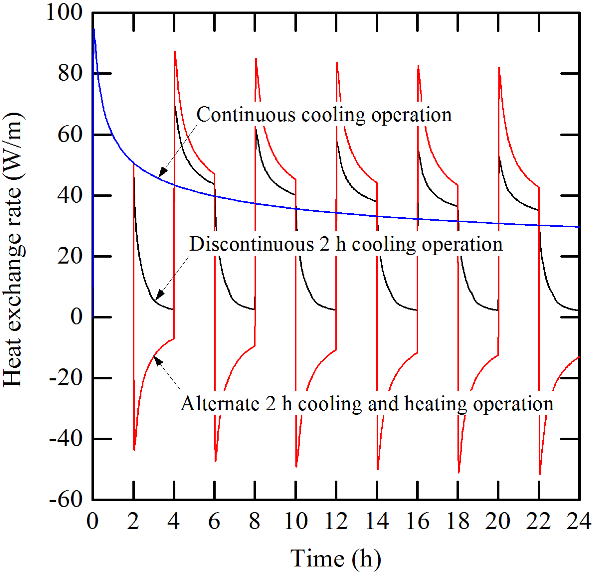
3.2. Discontinuous and Alternate 2 h Operation
In discontinuous 2 h operation, the HGHE was simulated in cooling mode for 2 h and followed by 2 h of no operation or off period in which water flow rate was shut-off completely. Meanwhile, in alternate 2 h operation, the HGHE was simulated in cooling mode for 2 h and the subsequent 2 h in heating mode. Heat exchange rate for both operations was compared against that in continuous cooling operation, as shown in
Figure 7. As discussed earlier, the heat exchange rate was high at beginning of operation and gradually declined due to the effect of heat buildup in the ground along with operating time.
Figure 7.
Heat exchange rate in discontinuous 2 h operation in cooling mode and alternate 2 h operation between cooling and heating mode.
Figure 7.
Heat exchange rate in discontinuous 2 h operation in cooling mode and alternate 2 h operation between cooling and heating mode.
Table 3 summarizes heat exchange rate for the short time period of operations at the end of cooling cycle. At the end of 22 h operation time, the heat exchange rate in discontinuous 2 h and alternate 2 h operations shows 16% and 42% increase, respectively, compared to that in continuous operation. At the same time, alternate 2 h operation performed 22% higher than discontinuous 2 h operation. The off period lessened the effect of heat buildup by dissipating the energy, thus improving the heat exchange rate in the next flow cycle. Thus the ground is allowed to recuperate its thermal condition during this period while water inside the HGHE is still rejecting heat at a much lesser extent. Alternating cooling and heating modes further increases the alleviation of heat buildup. The cooler water flow helps to extract heat, thus reducing the thermal saturation in the ground.
Table 3.
Summary of heat exchange rate in discontinuous 2 h operation in cooling mode and alternate 2 h operation between cooling and heating mode.
Table 3.
Summary of heat exchange rate in discontinuous 2 h operation in cooling mode and alternate 2 h operation between cooling and heating mode.
| Heat Exchange Rate (W/m) |
|---|
| Operation Time (h) | 2 | 6 | 10 | 14 | 18 | 22 |
|---|
| Continuous | 50.9 | 39.8 | 35.6 | 33.1 | 31.5 | 30.2 |
| Discontinuous 2 h | 50.9 | 43.6 | 40.2 | 39.0 | 36.4 | 35.1 |
| Alternate 2 h | 50.9 | 47.1 | 45.3 | 44.2 | 43.4 | 42.8 |
3.3. Discontinuous 9 h and 12 h Operation a Day
In this section, an office building operating in cooling operation was analyzed. Two operation hours were applied from 9:00 a.m. to 6:00 p.m. for 9 h operation and from 9:00 a.m. to 9:00 p.m. for 12 h operation a day during a seven days period. As described previously, the same flow conditions was applied with flow rate set at 4 L/min during operation and 0 L/min during off period. The inlet temperature was fixed at 35 °C.
Table 4 summarizes the heat exchange rate in discontinuous 9 and 12 h operations in cooling mode. The heat exchange rate was compared against that in continuous operation as presented in
Figure 8. Near the end of Day 7, the minimum heat exchange rate in 9 h operation increases by 33% and in 12 h operation, 21% compared to continuous operation. As can be observed, the extended period of off period increases the heat exchange rate in the next flow cycle.
Table 4.
Summary of heat exchange rate in discontinuous 9 and 12 h operation in cooling mode at the end of each cycle.
Table 4.
Summary of heat exchange rate in discontinuous 9 and 12 h operation in cooling mode at the end of each cycle.
| Heat Exchange Rate (W/m) |
|---|
| Operation Time (day) | 0.75 | 1.75 | 2.75 | 3.75 | 4.75 | 5.75 | 6.75 |
| Continuous | 36.4 | 27.6 | 24.4 | 22.5 | 21.1 | 20.0 | 19.1 |
| Discontinuous 9 h | 36.4 | 32.1 | 30.0 | 28.3 | 27.1 | 26.1 | 25.3 |
| Operation Time (day) | 0.875 | 1.875 | 2.875 | 3.875 | 4.875 | 5.875 | 6.875 |
| Continuous | 34.2 | 27.1 | 24.1 | 22.3 | 20.9 | 19.6 | 19.0 |
| Discontinuous 12 h | 34.2 | 29.8 | 27.5 | 25.9 | 24.7 | 23.7 | 22.9 |
Figure 8.
Heat exchange rates in discontinuous 9 h and 12 h operations in a day.
Figure 8.
Heat exchange rates in discontinuous 9 h and 12 h operations in a day.
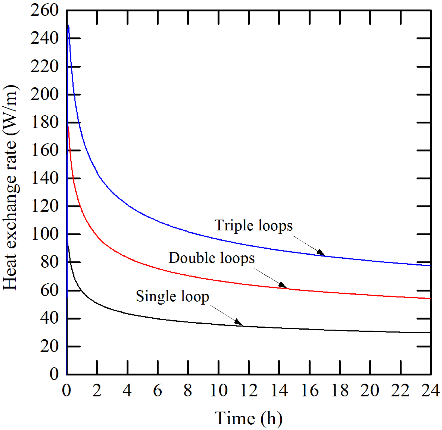
3.4. Parallel Loops Operation
In the interest of predicting thermal performance of parallel loops, double and triple loops operation were simulated in cooling mode. Initially, each identical loop was positioned close to one another in which edge-to-edge loops spacing between them equal 0 m. Each configuration was in continuous 24 h operation with the total flow rate set at 4 L/min, equal to the pumping work for single loop operation. Heat exchange rate in parallel loops operation was compared against that in single loop operation as presented in
Figure 9. The results summarized in
Table 2 are recalled. Compared to single loop operation, the mean heat exchange rate for double loops operation improved by 83%, meanwhile, for triple loops operations, 162%.
Figure 9.
Heat exchange rate in parallel loops operation with no spacing compared to single loop operation.
Figure 9.
Heat exchange rate in parallel loops operation with no spacing compared to single loop operation.
With the same circulation pump work, parallel loops operation promotes higher efficiency compared to single loops operation as heat transfer area is multiplied in this configuration. Hence it is more sensible to install and operate HGHE in parallel consisting of short series rather than one long series of loops. Parallel loops operation also benefits GSHP systems whereby less amount of pressure is required to overcome friction losses through each individual series thus minimizing pressure drop. However, it is worth noting that the turbulence inside the loops is reduced in distributed flow. Installations with parallel loops HGHE require additional initial costs concerning amount of pipe material and excavation works. Surplus land area is also required for such installations. However, in the long run, these extra investments would pay off due to higher thermal performance that is attainable.
It is reckoned that heat transfer from adjacent parallel loops interfere with each other causing a decrease in overall thermal performance. Further investigations were carried out to determine the effect of spacing between adjacent loops on heat exchange rate. Spacing of 0.5 m, 1.0 m, 2.0 m and 4.0 m were imposed between the nearest adjacent loop walls as shown in
Figure 10.
Figure 11 and
Figure 12 show the effect of spacing on heat exchange rate for double and triple loops operation, respectively. With a minimum spacing of 0.5 m provided, the increase of heat exchange rate becomes noticeable. For double loops operation, the optimum separating distance between adjacent loops is 1.0 m where the mean heat exchange rate increases by 10% compared to that in no spacing. For triple loops operation, the optimum spacing is at 2.0 m with the mean heat exchange rate increase of 14%. Although the differences are negligible, heat transfer should increase with greater loops spacing, as there would be less thermal interference between loops. The minor discrepancy in this analysis is thought to be caused by varying cell size in the modeling, particularly between the loops, in order to optimize the mesh size.
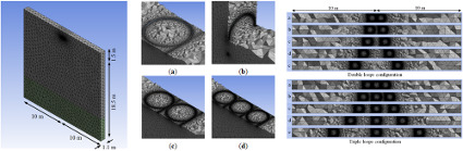
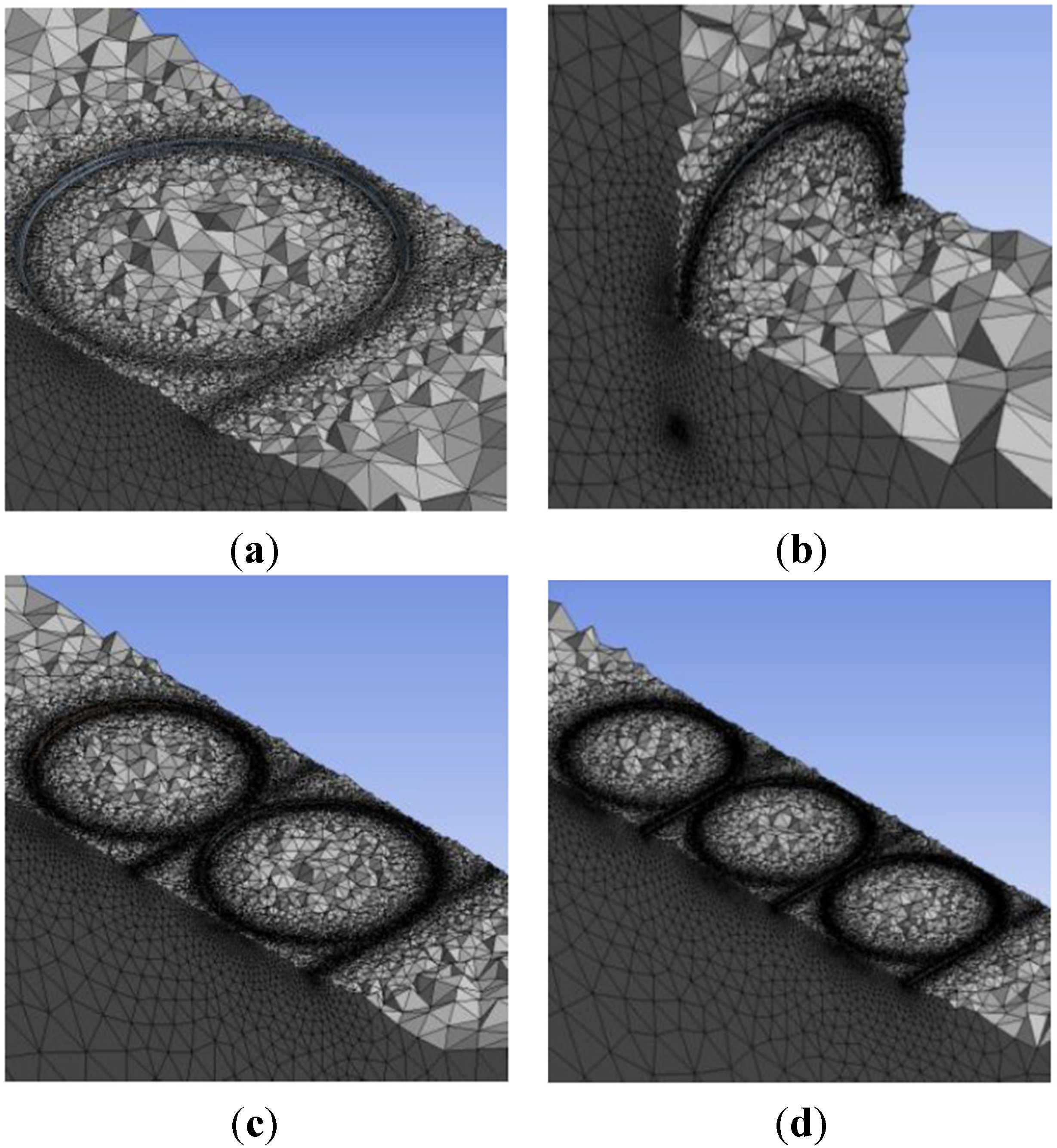
Figure 10.
Top section view at 1.5 m deep of spacing in parallel loops operation: (a) 0 m; (b) 0.5 m; (c) 1.0 m; (d) 2.0 m; and (e) 4.0 m.
Figure 10.
Top section view at 1.5 m deep of spacing in parallel loops operation: (a) 0 m; (b) 0.5 m; (c) 1.0 m; (d) 2.0 m; and (e) 4.0 m.
Figure 11.
The effect of spacing on heat exchange rate in parallel double loops operation.
Figure 11.
The effect of spacing on heat exchange rate in parallel double loops operation.
Figure 12.
The effect of spacing on heat exchange rate in parallel triple loops operation.
Figure 12.
The effect of spacing on heat exchange rate in parallel triple loops operation.
4. Conclusions
In this research, numerical simulation of HGHE was performed for a short time period of operation in discontinuous, alternate and parallel loops and the results were compared to that in continuous operation. Time- and position-varying parameters were used in the analysis to predict realistically the thermal performance of each operation. The prediction of thermal performance prior to the introduction of a GSHP system is important to determine the economic feasibility of a system design.
The orientation of HGHE installation is not as important, as it has a minor effect on thermal performance. The thermal performance for vertical orientation provides a slight improvement of 0.8% in mean heat exchange rate compared to horizontal orientation. The analysis shows that although the trench depth increased by one third in vertical orientation, the heat exchange rate only improved marginally compared to that in horizontal orientation. As a matter of fact, installation of HGHE in vertical orientation requires extra trenching work and it increases the initial cost. However, vertical orientation would be a practical solution in a proposed installation where land area is limited.
The analysis suggests that the higher the thermal conductivity of the material used as a HGHE loop, the higher the heat exchange rate. This can be observed in the increase of mean heat exchange rate for copper loop by 48% compared to HDPE loop. As the pipe material was substituted with one having over 800 times higher thermal conductivity, the increase of thermal performance was disproportionate to the increase of thermal conductivity of the tested materials. Despite that higher heat exchange rates are achievable using more conductive pipe materials, the analysis supports the common claim that the heat exchange rate is predominantly limited by the thermal conductivity of the ground.
In discontinuous operation, the water inside the loop is still rejecting heat at a lesser rate while the ground is allowed to restore its thermal balance before the next cycle starts. In discontinuous 2 h operation, the heat exchange rate was 16% higher when the last cycle stops at 22 h operation time compared to in continuous operation. In a more practical comparison for a typical office building, discontinuous cooling operation, the heat exchange rate increases by 33% in 9 h a day operation and 21% in 12 h a day operation compared to continuous operation near the end of Day 7. The effect of heat buildup in the ground is further lessened by operating the loop in alternate cooling and heating modes. The cooler water flow during heating mode reduces thermal saturation in the ground thus further improves heat exchange rate.
The thermal performance of double and triple loops operation was, respectively, 83% and 162% higher compared to that in single loop operation with the same amount of pumping work supplied. While greater heat contact area is provided in parallel loops configuration, the pipe material cost increases in tandem and consequently requires more land area for such installation. The thermal performance in parallel operations can be further optimized to 10%–14% increase when spacing between adjacent loops was provided. It is reckoned that spacing between adjacent parallel loops is provided to minimize the interference of heat flow that would penalize the overall thermal performance.
Numerical simulation of HGHE involving discontinuous operation should address the thermal behavior at the boundary conditions, particularly during off period. In order to further improve the analysis, a dynamic approach is suggested to be imposed on the temperature inlet during this period to reflect a more accurate condition. It is also suggested to extend the operation period in the analysis to reach better understanding of the overall thermal performance.


