
Metamaterial Impedance Matching Network for Ambient RF-Energy Harvesting Operating at 2.4 GHz and 5 GHz


Grupo de Aplicaciones Electro-Magnéticas Industriales (GAEMI), Departament d’Enginyeria Electrònica, Universitat Autonòma de Barcelona (UAB), Cerdanyola del Vallés, 08193 Barcelona, Spain
*
Author to whom correspondence should be addressed.
Electronics 2021, 10(10), 1196; https://doi.org/10.3390/electronics10101196
Submission received: 8 March 2021
/
Revised: 12 May 2021
/
Accepted: 14 May 2021
/
Published: 17 May 2021
(This article belongs to the Section Microwave and Wireless Communications)
Abstract
:This paper points out the viability of the utilization of metamaterial transmission lines as a multifrequency impedance matching network, improving RF-Energy Harvesting systems operating around 2.4 GHz and 5 GHz. Metamaterial transmission lines introduce additional degrees of freedom in the transmission line design, providing the possibility to match the impedance in multiple bands. The impedance matching structure has been designed and optimized using ADS simulator to match the input impedance of a four-diode-bridge rectifier connected to an energy management system. The proposed Metamaterial Impedance Matching Network (MIMN) has been fabricated using standard PCB technologies and tested in a full operative ambient RF-Energy Harvesting System obtaining a DC output voltage of 1.8 V in a 6.8 mF supercapacitor.
1. Introduction
RF-Energy Harvesting (RF-EH) systems have been a recurrent topic for the last decade [1,2,3,4,5,6]. The possibility of wireless feeding field sensors [7,8], RF-ID tags, or IoTs devices is closer every day [9,10,11], not only due to the tendency to reduce the power of each computational operation [10], but also due to the proliferation of the wasted ambient RF energy, produced by the continuous and growing wireless communication systems deployment [6,11,12,13,14,15,16]. Although there is a general consensus in the constituent functional blocks of a RF-EH system, different architectures and strategies have been proposed [3,4,12] including the possibility of combining the extraction of information and power from the same transmission [17,18]. However, from the point of view of the amount of collected energy, it is evident that a multiple frequency or broadband approach is the most convenient strategy, in order to take maximum advantage of the available ambient RF energy [14,19,20]. Examples of single [2], dual [14,21,22], multiple [12,13,15,23], and broadband frequency RF-EH systems [19,20] can be found in the literature. This work is framed in a basic stand-alone scheme, in which the energy is accumulated in a general-purpose storage element for further use. The Metamaterial Impedance Matching Network (MIMN) proposed in this work enhances the efficiency of a full ambient RF-EH system operating at 2.4 GHz and 5 GHz. Nevertheless, the technique could be extended to multiple bands by using metamaterial EBG transmission line structures controlling the electrical properties in multiple conduction bands. The rest of the functional blocks of the harvesting system are implemented using commercial-of-the-shell (COTS) elements. The antenna is a 2.5–5 GHz dual band from Molex [24], the rectification circuit is a full rectifier four-diode-bridge with SMS7630 Schottky diodes [25]; the Energy Management System (EMS) is a charge pump circuit based on the BQ25570 IC from Texas Instruments [26]. Finally, a 6.8 mF supercapacitor has been used as storage element due to its low losses and high speed response [27].
RF harvesting is based on the rectification and filtering of high frequency signals, which is inherently a highly non-linear process that challenges the impedance adaptation process. Several rectifier architectures such as the Garetz bridge [2,28,29,30], variations of the Dickson charge pump-rectifier circuits [31,32,33], or the Grenache rectifier [8,9,10,11,12,13], are commonly used in RFEH systems. In this design, the Garetz or bridge full wave rectifier has been chosen due to its simplicity and the fact that it is able to supply enough voltage to activate the input port of the BQ25570 nano power boost charger IC. Grenache and Dickson rectifiers introduce additional lumped capacitor that increases losses at the ultra-low power operation conditions. Communication classic impedance matching circuits are designed to guarantee the maximum power transfer at a single frequency, acting as a filter for the rest of the spectrum. The major power contribution in indoor environments is expected to be produced by the wireless domestic communication networks and specifically from Wi-Fi routers operating in the 2.4 GHz and 5 GHz bands [21,22].
The impedance matching has been one of the metamaterial applications since the popularization of the metamaterial concept introduction by J. Pendry [34] and D. Smith [35]. J. Mosig and C. Caloz, theoretically demonstrated the possibility of matching multiple bands using an extended composite right/left-handed transmission line [36]. An impedance matching EBG microstrip structure was proposed, fabricated, and tested in [37] using a composite right/left-handed transmission planar transmission line, including grounded vias. A dual band matching structure using Split Ring Resonators (SRR) was proposed in [38]. In this case, the utilization of SRR allows size reduction at the cost of degrading the quality factor and complicating the design process since there is not a clear relation between the physical dimensions of the microstrip structure and the SRR electrical parameters. Recently, other works point out the benefits of metasurfaces as impedance matching networks [5,39,40]. On the other hand, several optimization methods without any physical implementation, have been proposed to match the impedance using composite right/left-handed transmission lines in [41,42,43].
This work proposes the design, implementation, and test of a compact original microstrip MIMN structure, optimized using the ADS. Unlike other theoretical approaches or concept demonstrators, the proposed MIMN prototype performance is tested in a real and fully operative ambient RF-EH system.
2. MIMN Background and Design Process
Metamaterial transmission lines can be described by an equivalent circuit model containing a series capacitance (C) and a grounded inductance (L) [44]. The MIMN proposed in this work is formed by two symmetric stacks of microstrip resonators, capacitively coupled. The lateral coupling between the stubs, implements the metamaterial series capacitance. The resonators behave as parallel RLC resonators around the resonant frequency. However, it can be shown that for the imaginary part of the stub impedance is positive. In this case, neglecting loses, the equivalent circuit is basically a grounded L [45] that implements the shunt inductance of the metamaterial equivalent circuit model.
Figure 1 shows the equivalent circuit model of the MIMN structure. It can be easily shown that the characteristic impedance of the metamaterial transmission line is ruled by Equation (1).
Unlike conventional transmission lines, L and C are independent variables in the metamaterials, which can be controlled by the stub length and width, and the inter-stub coupling distance. Due to the additional degrees of freedom, metamaterial transmission lines can be used to match the impedance in multiple frequencies.
The MIMN design process starts with the definition of the microstrip length (l) of the stubs to obtain the two first resonances at 2.4 GHz and 4.8 GHz. The chosen substrate for the implementation is an Arlon 1000 with a dissipation factor of 0.003 and a high dielectric constant of , obtaining a compromise between minimal size, structural robustness, and low losses at the operating frequencies. The substate thickness is 1.27 mm (50 mils) with top and bottom coper layers. The MIMN design is controlled by 4 parameters: the stubs length , the stubs width , the separation between adjacent stubs , and the gap between the input microstrip port and the stubs . The central frequency of the operating bands is determined by the stub length that determines the resonant frequency. Initial values for L and C can be analytically evaluated from the structure dimensions using classical well known expressions [46].
The design process finishes with the optimization of the MIMN loaded with the measured input impedance of the rectifier-EMC system. According to equation (2), the perfect match implies . The optimization process uses the length of the stubs () and the gap between microstrip ports ( as parameters to minimize around the two first stubs resonant frequencies. In the process, the minimal width stubs and inter-stub gap have been fixed to 1 mm and 0.2 mm which are the minimal allowed fabrication distances.
It has been experimentally verified that (and consequently ) of the bridge rectifier loaded with the EMS system, does not depend significantly on the input power in the range between 0 dBm and −20 dBm. Figure 2 shows the final dimensions resulting from the optimization process and a picture of the microstrip top layer of the fabricated MIMN structure.
The MIMN is a passive two port network that generates S11 notches around the open stubs resonators. These notches can be identified as resonant frequencies that minimize the S11 parameter. The number of notches in the structure response is related to the number of coupled stubs. Two identical open stubs capacitively coupled generate two split resonant frequencies around the original resonance (see chapter 8 of [47]). In general N stubs will generate N-1 notches; however, the quality factor of the new resonant frequencies decreases with N. The distance between the split frequencies depends on the coupling coefficient between the resonators which, in our case is basically controlled by the distance between adjacent stubs. Therefore, this coupling distance in an optimization process can situate a deep notch at the desired frequency (2.4 GHz in our case). The MIMN takes advantage of these notches behavior to match the input impedance of the EMS in multiple frequencies simultaneously.
The matched system has been simulated using ADS-Momentum co-simulation, combining the MIMN Momentum electro-magnetic model with the circuit bridge schematic. The SMS7630 model is generated by introducing the information supplied in the diode datasheet [25]. Figure 3 shows a reasonable agreement between the simulated and measured S11 parameters. Several notches are observed in both simulated and measured S11 curves, situated around the two first resonances of the stubs. The number of notches is related to the number of unit cells in the metamaterial structure: 3 for the first resonance and 6 for the second (although some of them could be degenerated). S11 reaches minimal values of −36.54 dB at 2.0 GHz and −28.04 dB at 5 GHz, indicating that the input and load impedance differ in 2.8%, and 3.9%, respectively. There is a notch in the measured response at 2.4 GHz with S11 = −16.63 dB indicating a difference of 28% between the impedances. Consequently, it can be said that the MIMN is matched in these notches.
The matched system has been simulated using ADS-Momentum co-simulation, combining the MIMN Momentum electro-magnetic model with the circuit bridge schematic. The SMS7630 model is generated by introducing the information supplied in the diode datasheet [25]. Figure 3 shows a reasonable agreement between the simulated and measured S11 parameters. Several notches are observed in both simulated and measured S11 curves, situated around the two first resonances of the stubs. The number of notches is related to the number of unit cells in the metamaterial structure: 3 for the first resonance and 6 for the second (although some of them could be degenerated). S11 reaches minimal values of −36.54 dB at 2.0 GHz and −28.04 dB at 5 GHz, indicating that the input and load impedance differ in 2.8% and 3.9%, respectively. There is a notch in the measured response at 2.4 GHz with S11 = −16.63 dB indicating a difference of 28% between the impedances. Consequently, it can be said that the MIMN is matched in these notches.
Figure 4 shows the measured impedance correction introduced by the MIMN in the bridge input impedance at the three main notch frequencies. MIMN effect can be interpreted as the result of a network with grounded inductance and shunt capacitance, which is coherent with the equivalent circuit model described in Figure 1. On the other hand, Figure 4 points out the multi-frequency impedance matching feature of the MIMN, obtaining a reasonable matching for three different frequencies with a single network.
3. Experimental Setup to Evaluate the MIMN
The effectivity of the MIMN has been evaluated by comparing its effect in a full operational RF-EH system performance. Except for the proposed MIMN, the RF-EH constituent blocks have been implemented using COTS elements. Figure 5 shows the components used in the implementation of the different RF-EH functional blocks.
RF-EH prototype measurements have been performed in normal ambient laboratory conditions. The nearest Wi-Fi source was a router outside the room, 5 m away from the testing point.
Figure 6 shows the ambient power level captured by the planar Molex Combo antenna during a period of 5 min using the max-hold mode in the spectrum analyzer. After that period no further changes are observed in the measured spectrum. This measurement is used as the maxim RF power available in the ambient for the effective efficiency evaluation. The rectifier circuit is loaded with a 6.8 mF supercapacitor [27], zero bias Schottky diode [25] in a bridge rectifier. The 6.8 mF supercapacitor feeds an in-home developed EMS based on the BQ25570 IC [26]. Temporal variability of RF signals generates an unpredictable input power dynamic, hindering the determination of optimal input power conditions [2]. The BQ25570 IC implements a programmable maximum power point tracking (MPPT) sampling network, that optimizes and periodically updates the input power conditions. Thanks to this MPPT, the EMS is able to efficiently collect at the input ports and deliver pulses to the output storage element. The MPPT system checks the voltage in the EMS input every 16 s, recalculating the optimum input operating point for 256 ms, to resume the charge pumping in updated optimal conditions.
A 6.8 mF AVX BestCap Ultra-low ESR high power pulse supercapacitor [27] has been used as the storage element. This supercapacitor minimizes internal losses offering a fast response, suitable for powering RF-systems. The EMS PCB (Harvest-1) includes the bridge rectifier. The EMS offers three different outputs with maxim voltages ranging from 1.8 V to 4.2 V. For convenience, the 1.8 V output. has been chosen to evaluate the MIMN effect in the RF-EH performance.
Figure 7a,b show the schemes of the experimental setups with and without the MIMN. Figure 7c corresponds to an image of the implemented RF-EH system. The EMS is a self-powered system which operates in two different modes: the cold state (characterized by , and the efficient state (characterized by . In the cold state, the collected charge is used to setup the EMS self-polarizing IC voltages. A minimum of 330 mV, and current pulses with amplitudes large enough to generate power are required in the EMS input port. Above this threshold, the EMS starts to accumulate charge in the self-polarization capacitors. When reaches 1.6 V the EMS switches to a highly efficient mode in which the input minimal voltage to operate is reduced to a value between 80 mV and 100 mV. Once the 1.8 V is reached at the output storage element, the EMS stabilizes the voltage producing oscillations around 1.8 V.
The function of the 6.8 mF supercapacitor connected to the rectifier output and the EMS input port, is to accumulate enough charge to supply power packages keeping the 330 mV needed in the cold state (or 80 mV in the high efficiency state) minimizing losses.
4. Experimental Results and Discussion
Some authors have proposed the elimination of the lumped LC impedance matching networks in low power RF-EH, arguing that losses introduced by the network in these conditions may be comparable with the matching benefits [47,48]. Since one of the metamaterial transmissions line characteristics is the high losses, it has been found interesting to compare the RF-EH system performance with and without the proposed MIMN.
Results shown in Figure 8, Figure 9 and Figure 10 for the EMS input and output voltage, indicate that the MIMN enhances the RF-EH performance despite the losses. Figure 8 shows the voltage evolution at the EMS input () with and without the MIMN. During the cold state, rises from zero to values between 330 mV and 270 mV. In this state, the harvested energy is used to accumulate charge in the EMS self-polarizing capacitors. On each voltage oscillation 408 is pumped into the EMS. As it can be observed in Figure 8, the charge pumping frequency is 50% faster when using MIMN.
The system formed by the antenna, the full wave rectifier, and the capacitor is a RF-DC transductor where the DC voltage is basically generated by the charge stored in 6.8 mF supercapacitor. This high speed and low loss storage element bias the EMS input and supplies the charge pumped into the battery by the EMS.
Figure 9 shows the switch between the cold state (characterized by oscillations between 330 mV and 270 mV) and the efficient state (characterized by a few mV oscillations around 80 mV), with (black line) and without (red line) using the MIMN.
The efficiency is the usual figure of merit used to characterize RF rectification process. It is strongly conditioned by the input impedance and the input power. Figure 10 shows the simulated efficiency of the bridge rectifier obtained through ADS harmonic balance analysis. SMS7630 datasheet information [25] has been included in the ADS Schottky diode model for simulations.
The available RF power in the ambient is in constant and unpredictable evolution. It depends on the WI-FI information transit but also on the number of active devices around and the proximity to the RF-EH system to the sources. It is reasonable to expect RF ambient power levels below −30 dBm (as it was shown in Figure 6). Figure 11 shows the efficiencies vs. input power for 2.4 and 5 GHz, using as RL the input impedance of the EMS ().
As it can be seen in Figure 11, the expected efficiencies for a −30 dBm input power are below 15% at 2.4 GHz and below 2.5% at 5 GHz. Since there is available power in the 5.5 GHz band (see Figure 6), the efficiency has been also evaluated at this frequency; however, it is not expected a significant contribution to the RF-EH performance from this frequency. Similar efficiencies can be found in the literature [49,50,51] for RF low-power conditions (see Table 1).
The rectifier efficiency characterization shown in Figure 11 utilizes a monochromatic RF source to generate the input power () and an output load ( to evaluate the output power (). The effects of the load resistance in the efficiency can be observed in Figure 12. The maximum efficiency is observed for , while in the case (the EMS input impedance) the efficiency is below 10%.
The efficiency of the bridge rectifier with the MIMN is evaluated by simultaneously measuring the maxim ambient power in the 2.4 GHz WI-FI band, and the output voltage for different . Unfortunately, the matching notches observed in Figure 3 indicate that the 5.5 GHz band observed in Figure 6 does not contribute to the RF input power. The obtained measured efficiency estimation (dots plotted in Figure 12) shows the same behavior as the harmonic balance simulations at 2.4 and 5 GHz, indicating an 8.8% efficiency for for the rectification of the RF ambient power.
The EMS extracts charge from the capacitor and pump it in a storage element (battery or supercapacitor) up to 1.8 V. The EMS requires as minimum input voltage to operate in the cold state, and in the efficiency state to operate as a charge pump. These values constitute the RF-EH threshold voltages that delimitate the sensibility of the EH system. Figure 13 shows the measured output voltage of the MIMN bridge rectifier system for different output loads and RF-ambient input power.
Figure 13 points out that the RF-EH matched with the MIMN is able to activate the charge pump of the EMS from the available RF ambient power. The efficiency is low, however, the possibility of matching multiple frequencies using the MIMN constitutes an interesting result to explore in further designs.
5. Conclusions
In this paper, a metamaterial impedance matching network (MIMN) has been designed, implemented, and tested, to match the impedance of an ambient RF-EH system. The metamaterial transmission line is based on coupled microstrip resonators, being easy to control the central operating frequencies with the stubs dimensions. Three matched frequencies have been observed in the s-parameter measures of the matched RF-EH system: , , and . The utilization of the MIMN enhances in a 50% the charging time of the RF-EH when the ambient power is below −30 dBm. The efficiency of the matched rectifier has been experimentally estimated in 8.8% for . The possibility of matching multiple frequencies simultaneously constitutes a promising result to be applied in further designs.
Author Contributions
E.C. was involved in the design, measurement, and the preparation of the manuscript. J.J.G.-G. was involved in the conceptualization, methodology, validation and preparing the manuscript. All authors have read and agreed to the published version of the manuscript.
Funding
This research has been funded by the Grupo de Aplicaciones Electro-Magnéticas Industriales (GAEMI) of the Departament d’Enginyeria Electrònica de la Universitat Autònoma de Barcelona.
Conflicts of Interest
The authors declare no conflict of interest.
References
- Li, L.; Zhang, X.; Song, C.; Huang, Y. Progress, challenges, and perspective on metasurfaces for ambient radio frequency energy harvesting. Appl. Phys. Lett. 2020, 116. [Google Scholar] [CrossRef]
- Luo, Y.; Pu, L.; Wang, G.; Zhao, Y. RF energy harvesting wireless communications: Rf environment, device hardware and practical issues. Sensors 2019, 19, 3010. [Google Scholar] [CrossRef] [PubMed] [Green Version]
- Luo, Y.; Pu, L.; Zhao, Y.; Wang, W.; Yang, Q. A Nonlinear Recursive Model Based Optimal Transmission Scheduling in RF Energy Harvesting Wireless Communications. IEEE Trans. Wirel. Commun. 2020, 19, 3449–3462. [Google Scholar] [CrossRef] [Green Version]
- Cansiz, M.; Altinel, D.; Kurt, G.K. Efficiency in RF energy harvesting systems: A comprehensive review. Energy 2019, 174, 292–309. [Google Scholar] [CrossRef]
- Alibakhshikenari, M.; Virdee, B.S.; See, C.H.; Abd-alhameed, R.A.; Limiti, E. Energy Harvesting Circuit with High RF-to-DC Conversion Efficiency. In Proceedings of the 2020 IEEE International Symposium on Antennas and Propagation and North American Radio Science Meeting, Montreal, QC, Canada, 5–10 July 2020; pp. 1299–1300. [Google Scholar] [CrossRef]
- Gu, X.; Grauwin, L.; Dousset, D.; Hemour, S.; Wu, K. Dynamic Ambient RF Energy Density Measurements of Montreal for Battery-Free IoT Sensor Network Planning. IEEE Internet Things J. 2021, 4662. [Google Scholar] [CrossRef]
- Karampatea, A.; Siakavara, K. Synthesis of rectenna for powering micro-watt sensors by harvesting ambient RF signals’ power. Electronics 2019, 8, 1108. [Google Scholar] [CrossRef] [Green Version]
- Nintanavongsa, P. A survey on RF energy harvesting: Circuits and protocols. Energy Procedia 2014, 56, 414–422. [Google Scholar] [CrossRef] [Green Version]
- Takacs, A.; Okba, A.; Aubert, H.; Charlot, S.; Calmon, P.F. Recent advances in electromagnetic energy harvesting and Wireless Power Transfer for IoT and SHM applications. In Proceedings of the 2017 IEEE International Workshop of Electronics, Control, Measurement, Signals and their Application to Mechatronics (ECMSM 2017), Donostia, Spain, 24–26 May 2017. [Google Scholar]
- Hemour, S.; Wu, K. Radio-frequency rectifier for electromagnetic energy harvesting: Development path and future outlook. Proc. IEEE 2014, 102, 1667–1691. [Google Scholar] [CrossRef]
- Muncuk, U.; Alemdar, K.; Sarode, J.D.; Chowdhury, K.R. Multiband ambient RF energy harvesting circuit design for enabling batteryless sensors and IoT. IEEE Internet Things J. 2018, 5, 2700–2714. [Google Scholar] [CrossRef]
- Shen, S.; Chiu, C.Y.; Murch, R.D. Multiport Pixel Rectenna for Ambient RF Energy Harvesting. IEEE Trans. Antennas Propag. 2018, 66, 644–656. [Google Scholar] [CrossRef]
- Liu, Z.; Zhong, Z.; Guo, Y.X. High-efficiency triple-band ambient RF energy harvesting for wireless body sensor network. In Proceedings of the 2014 IEEE MTT-S International Microwave Workshop Series on RF and Wireless Technologies for Biomedical and Healthcare Applications (IMWS-Bio2014), London, UK, 8–10 December 2014; pp. 15–17. [Google Scholar] [CrossRef]
- Sun, H.; Guo, Y.X.; He, M.; Zhong, Z. A dual-band rectenna using broadband yagi antenna array for ambient rf power harvesting. IEEE Antennas Wirel. Propag. Lett. 2013, 12, 918–921. [Google Scholar] [CrossRef]
- Shen, S.; Zhang, Y.; Chiu, C.-Y.; Murch, R. An Ambient RF Energy Harvesting System Where the Number of Antenna Ports is Dependent on Frequency. IEEE Trans. Microw. Theory Tech. 2019, 67, 3821–3832. [Google Scholar] [CrossRef]
- Piñuela, M.; Mitcheson, P.D.; Lucyszyn, S. Ambient RF energy harvesting in urban and semi-urban environments. IEEE Trans. Microw. Theory Tech. 2013, 61, 2715–2726. [Google Scholar] [CrossRef]
- Huang, J.; Xing, C.C.; Wang, C. Simultaneous Wireless Information and Power Transfer: Technologies, Applications, and Research Challenges. IEEE Commun. Mag. 2017, 55, 26–32. [Google Scholar] [CrossRef]
- Ponnimbaduge Perera, T.D.; Jayakody, D.N.K.; Sharma, S.K.; Chatzinotas, S.; Li, J. Simultaneous Wireless Information and Power Transfer (SWIPT): Recent Advances and Future Challenges. IEEE Commun. Surv. Tutor. 2018, 20, 264–302. [Google Scholar] [CrossRef] [Green Version]
- Song, C.; Huang, Y.; Carter, P.; Zhou, J.; Joseph, S.D.; Li, G. Novel Compact and Broadband Frequency-Selectable Rectennas for a Wide Input-Power and Load Impedance Range. IEEE Trans. Antennas Propag. 2018, 66, 3306–3316. [Google Scholar] [CrossRef]
- Arrawatia, M.; Baghini, M.S.; Kumar, G. Broadband Bent Triangular Omnidirectional Antenna for RF Energy Harvesting. IEEE Antennas Wirel. Propag. Lett. 2016, 15, 36–39. [Google Scholar] [CrossRef]
- Bhatt, K.; Kumar, S.; Kumar, P.; Tripathi, C.C. Highly Efficient 2.4 and 5.8 GHz Dual-Band Rectenna for Energy Harvesting Applications. IEEE Antennas Wirel. Propag. Lett. 2019, 18, 2637–2641. [Google Scholar] [CrossRef]
- Mattsson, M.; Kolitsidas, C.I.; Jonsson, B.L.G. Dual-band dual-polarized full-wave rectenna based on differential field sampling. IEEE Antennas Wirel. Propag. Lett. 2018, 17, 956–959. [Google Scholar] [CrossRef]
- Pan, N.; Belo, D.; Rajabi, M.; Schreurs, D.; Carvalho, N.B.; Pollin, S. Bandwidth Analysis of RF-DC Converters under Multisine Excitation. IEEE Trans. Microw. Theory Tech. 2018, 66, 791–802. [Google Scholar] [CrossRef]
- Molex. Wifi 6E Flex Cable Balance Antenna Product Specification. 2020. Available online: https://www.molex.com/pdm_docs/ps/PS-146153-100-001.pdf (accessed on 1 March 2021).
- Skyworks Solutions. Surface Mount Mixer and Detector Schottky Diodes. Datasheet. 2016. Available online: https://www.skyworksinc.com/-/media/A36775836A4E4BA8A92104088692424F.ashx (accessed on 1 March 2021).
- Texas Instruments. bq25570 Nano Power Boost Charger and Buck Converter. 2015. Available online: https://www.ti.com/lit/ds/symlink/bq25570.pdf (accessed on 1 March 2021).
- Avx. AVX BestCap Ultra-low ESR High Power Pulse Supercapacitors. 2013. Available online: http://catalogs.avx.com/BestCap.pdf (accessed on 1 March 2021).
- Visser, H.J.; Vullers, R.J.M. RF energy harvesting and transport for wireless sensor network applications: Principles and requirements. Proc. IEEE 2013, 101, 1410–1423. [Google Scholar] [CrossRef]
- Karampatea, A.; Siakavara, K. Hybrid rectennas of printed dipole type on Double Negative Dielectric Media for powering sensors via RF ambient energy harvesting. AEU Int. J. Electron. Commun. 2019, 108, 242–250. [Google Scholar] [CrossRef]
- Chang, Y.; Zhang, P.; Wang, L. Highly efficient differential rectenna for RF energy harvesting. Microw. Opt. Technol. Lett. 2019, 61, 2662–2668. [Google Scholar] [CrossRef]
- Chaour, I.; Fakhfakh, A.; Kanoun, O.; Tran, L.G.; Cha, H.K.; Park, W.T. Enhanced passive RF-DC converter circuit efficiency for low RF energy harvesting. Sensors 2017, 17, 546. [Google Scholar] [CrossRef] [Green Version]
- Marshall, B.R.; Morys, M.M.; Durgin, G.D. Parametric analysis and design guidelines of RF-to-DC Dickson charge pumps for RFID energy harvesting. In Proceedings of the 2015 IEEE International Conference on RFID (RFID), San Diego, CA, USA, 15–17 April 2015; pp. 32–39. [Google Scholar] [CrossRef]
- Mahfoudi, H.; Takhedmit, H.; Tellache, M.; Boisseau, S. Wireless sensor node remote supply using a compact stacked rectenna array with voltage multipliers at 2.45 GHz. Int. J. Microw. Wirel. Technol. 2020, 12, 309–315. [Google Scholar] [CrossRef]
- Pendry, J.B.; Holden, A.J.; Robbins, D.J.; Stewart, W.J. Magnetism from conductors and enhanced nonlinear phenomena. IEEE Trans. Microw. Theory Tech. 1999, 47, 2075–2084. [Google Scholar] [CrossRef] [Green Version]
- Smith, D.R.; Padilla, W.J.; Vier, D.C.; Nemat-Nasser, S.C.; Schultz, S. Composite medium with simultaneously negative permeability and permittivity. Phys. Rev. Lett. 2000, 84, 4184–4187. [Google Scholar] [CrossRef] [Green Version]
- Rennings, A.; Otto, S.; Mosig, J.; Caloz, C.; Wolff, I. Extended Composite Right/Left-Handed (E-CRLH) metamaterial and its application as quadband quarter-wavelength transmission line. In Proceedings of the 2006 Asia-Pacific Microwave Conference, Yokohama, Japan, 12–15 December 2006; pp. 1405–1408. [Google Scholar] [CrossRef]
- Damm, C.; Schüßler, M.; Freese, J.; Jakoby, R. Novel impedance matching approach employing the band gap region of composite right/left-handed artificial lines. In Proceedings of the 2007 European Microwave Conference, Munich, Germany, 9–12 October 2007; pp. 708–711. [Google Scholar] [CrossRef]
- Paredes, F.; Zamora, G.; Bonache, J.; Martin, F. Perturbation method based on resonant type metamaterial transmission lines for dual-band matching networks. In Proceedings of the 2009 Mediterrannean Microwave Symposium (MMS), Tangiers, Morocco, 15–17 November 2009. [Google Scholar] [CrossRef]
- Alibakhshikenari, M.; Virdee, B.S.; See, C.H.; Abd-Alhameed, R.A.; Falcone, F.; Limiti, E. Metasurface for controlling polarization of scattered em waves. In Proceedings of the 2020 4th Australian Microwave Symposium (AMS), Sydney, NSW, Australia, 13–14 February 2020; pp. 13–14. [Google Scholar] [CrossRef]
- Alibakhshikenari, M.; Virdee, B.S.; See, C.H.; Abd-Alhameed, R.A.; Falcone, F.; Limiti, E. Impedance Matching Network Based on Metasurfaces (2-D Metamaterials) for Electrically Small Antennas. In Proceedings of the 2020 IEEE International Symposium on Antennas and Propagation and North American Radio Science Meeting, Montreal, QC, Canada, 5–10 July 2020; pp. 1953–1954. [Google Scholar]
- Günel, T. A genetic approach to the synthesis of composite right/left-handed transmission line impedance matching sections. AEU Int. J. Electron. Commun. 2007, 61, 459–462. [Google Scholar] [CrossRef]
- Güneş, F.; Karataev, T.; Demirel, S. Composite right/left-handed transmission lines in use for ultra-wideband matching of front-end amplifiers with modified cuckoo search optimization. Int. J. Numer. Model. Electron. Netw. Devices Fields 2017, 30, e2144. [Google Scholar] [CrossRef]
- Karataev, T.; Gunes, F.; Demirel, S. Cuckoo search design optimization and analysis of matching circuits composed of CRLH transmission cells. In Proceedings of the 2015 Twelve International Conference on Electronics Computer and Computation (ICECCO), Almaty, Kazakhstan, 27–30 September 2015; pp. 2–5. [Google Scholar] [CrossRef]
- Eleftheriades, G.V.; Iyer, A.K.; Kremer, P.C. Planar negative refractive index media using periodically L-C loaded transmission lines. IEEE Trans. Microw. Theory Tech. 2002, 50, 2702–2712. [Google Scholar] [CrossRef]
- Pozar, D.M. Microwave Engineering; John Wiley & Sons, Inc.: Hoboken, NJ, USA, 2018; ISBN 978-0-470-63155-3. [Google Scholar]
- García-García, J.; Sans, B. Switchable microstrip bandpass-stopband filter based on periodically loaded transmission lines. In Proceedings of the 5th International Conference on Wireless Communications, Networking and Mobile Computing (WiCOM 2009), Beijing, China, 24–26 September 2009. [Google Scholar]
- Chen, Y.S.; Chiu, C.W. Maximum achievable power conversion efficiency obtained through an optimized rectenna structure for RF energy harvesting. IEEE Trans. Antennas Propag. 2017, 65, 2305–2317. [Google Scholar] [CrossRef]
- Chen, Y.S.; Chiu, C.W. Insertion Loss Characterization of Impedance Matching Networks for Low-Power Rectennas. IEEE Trans. Compon. Packag. Manuf. Technol. 2018, 8, 1632–1641. [Google Scholar] [CrossRef]
- Li, P.; Long, Z.; Yang, Z. RF Energy Harvesting for Batteryless and Maintenance-Free Condition Monitoring of Railway Tracks. IEEE Internet Things J. 2021, 8, 3512–3523. [Google Scholar] [CrossRef]
- Vital, D.; Bhardwaj, S.; Volakis, J.L. A 2.45 GHz RF Power Harvesting System Using Textile-Based Single-Diode Rectennas. IEEE MTT-S Int. Microw. Symp. Dig. 2019, 2, 1313–1315. [Google Scholar] [CrossRef]
- Visser, J.; Keyrouz, S.; Smolders, A.B. Optimized rectenna design. Wirel. Power Transf. 2015, 2, 44–50. [Google Scholar] [CrossRef] [Green Version]
- Sun, H.; Guo, Y.X.; He, M.; Zhong, Z. Design of a high-efficiency 2.45-GHz rectenna for low-input-power energy harvesting. IEEE Antennas Wirel. Propag. Lett. 2012, 11, 929–932. [Google Scholar] [CrossRef]
Figure 1.
Equivalent circuit model of the proposed structure around the stubs resonances of the capacitively coupled microstrips with a schematic of the MIMN around the microstrip stub resonant frequencies.
Figure 1.
Equivalent circuit model of the proposed structure around the stubs resonances of the capacitively coupled microstrips with a schematic of the MIMN around the microstrip stub resonant frequencies.
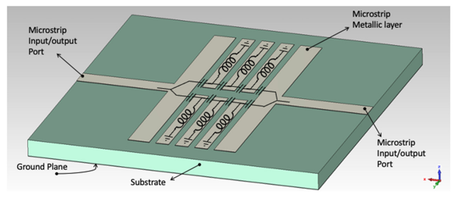
Figure 2.
(a) Layout of the MIMN microstrip top layer with the physical dimensions: length l = 22.8 mm, coupled stubs width w = 6.69 mm, inter coupled stubs gap g = 0.2 mm, and gaps to the input and output ports gp = 0.4 mm. (b) Image of the fabricated prototype.
Figure 2.
(a) Layout of the MIMN microstrip top layer with the physical dimensions: length l = 22.8 mm, coupled stubs width w = 6.69 mm, inter coupled stubs gap g = 0.2 mm, and gaps to the input and output ports gp = 0.4 mm. (b) Image of the fabricated prototype.

Figure 3.
(a) Measured and simulated parameter of the MIMN connected with the bridge rectifier for Pin = −15 dB. (b) Scheme of the measurement setup.
Figure 3.
(a) Measured and simulated parameter of the MIMN connected with the bridge rectifier for Pin = −15 dB. (b) Scheme of the measurement setup.

Figure 4.
Measured effect of the MIMN in the bridge input impedance represented in the normalized Smith Chart, for 2.0 GHz, 2.4 GHz, and 5.0 GHz.
Figure 4.
Measured effect of the MIMN in the bridge input impedance represented in the normalized Smith Chart, for 2.0 GHz, 2.4 GHz, and 5.0 GHz.
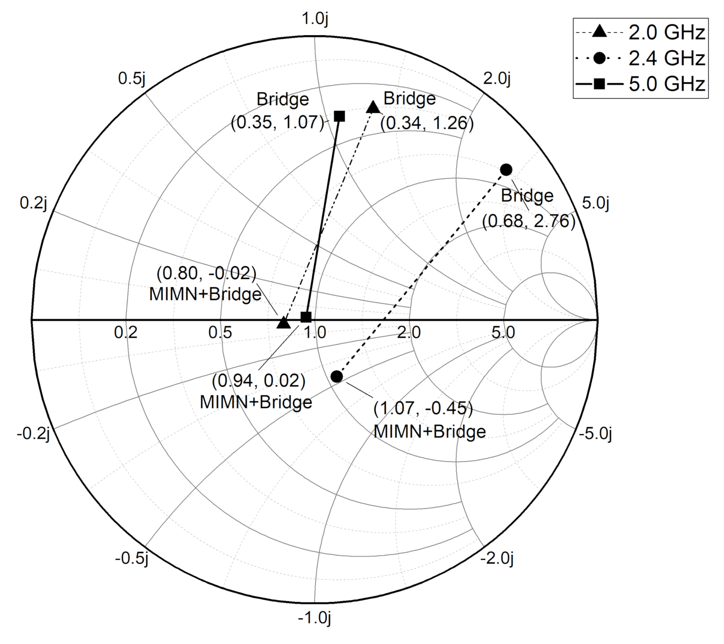
Figure 5.
Components used to implement the different functional blocks of the RF-EH prototype. From left to right: Planar Wi-Fi antenna Combo 47950-0001 by Molex [24]; proposed MIMN; full wave bridge rectifier using SMS7630-061 Schottky diodes [25], included in the Harvest-1 PCB; EMS based on the BQ25570 nano power boost charger and bust converter by Texas Instruments [26]; 6.8 mF supercapacitor AVX BestCap ultra-low ESR [27].

Figure 6.
Measure of the maximum RF ambient power delivered by the 47950-0001 Molex Combo antenna. The measurement has been done with a Rohde Schwartz FSL6 spectrum analyzer with a frequential using the max-hold mode.
Figure 6.
Measure of the maximum RF ambient power delivered by the 47950-0001 Molex Combo antenna. The measurement has been done with a Rohde Schwartz FSL6 spectrum analyzer with a frequential using the max-hold mode.
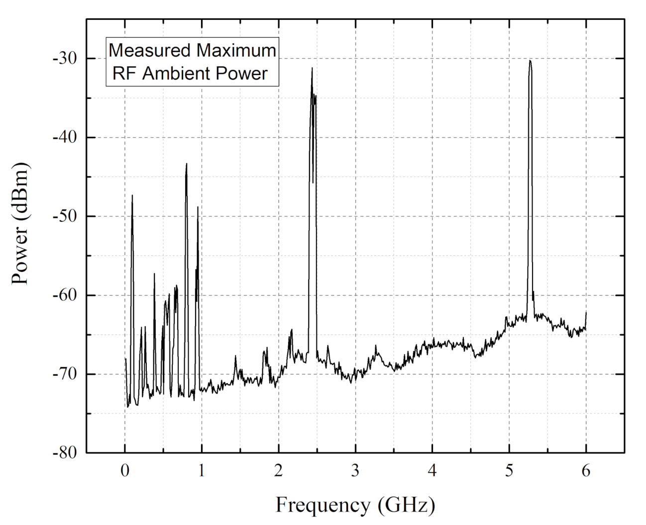
Figure 7.
(a) Scheme of the RF-EH with not matching network (NM). (b) Scheme of the RF-EH system with matching network (MIMN). (c) Images of the experimental setup.
Figure 7.
(a) Scheme of the RF-EH with not matching network (NM). (b) Scheme of the RF-EH system with matching network (MIMN). (c) Images of the experimental setup.
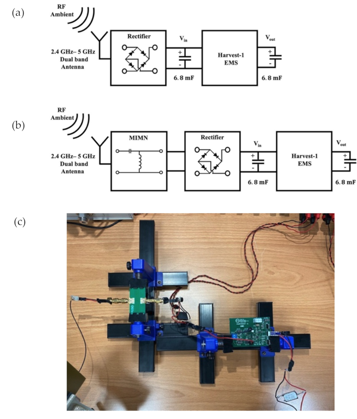
Figure 8.
EMS Input voltage transient with (MIMN RF-EH) and without (NM RF-EH) proposed Metamaterial Impedance Matching Network (MIMN).
Figure 8.
EMS Input voltage transient with (MIMN RF-EH) and without (NM RF-EH) proposed Metamaterial Impedance Matching Network (MIMN).
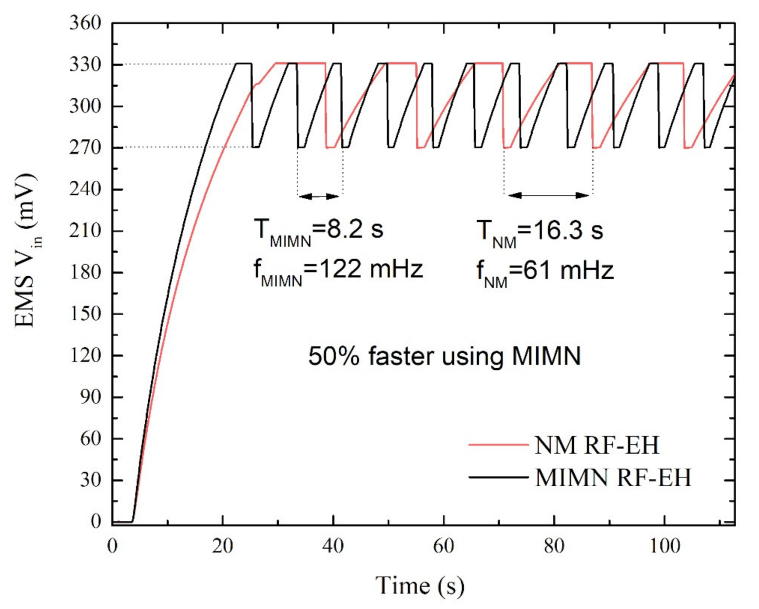
Figure 9.
EMS input voltage evolution at the EMS input ( in Figure 7a using MIMN (black line) and input ( in Figure 7b) without matching network (red line).
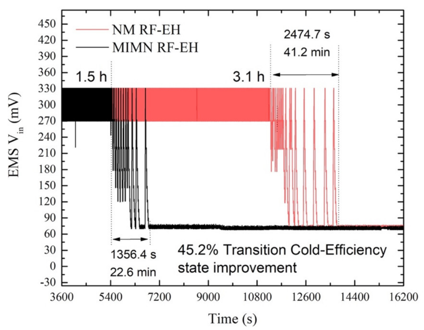
Figure 10.
EMS output voltage ( in Figure 7) using a 6.8 mF supercapacitor as output storage element. The evolution between 0 and 1.6 V corresponds to the cold state. exhibits a linear behavior in the range .
Figure 10.
EMS output voltage ( in Figure 7) using a 6.8 mF supercapacitor as output storage element. The evolution between 0 and 1.6 V corresponds to the cold state. exhibits a linear behavior in the range .
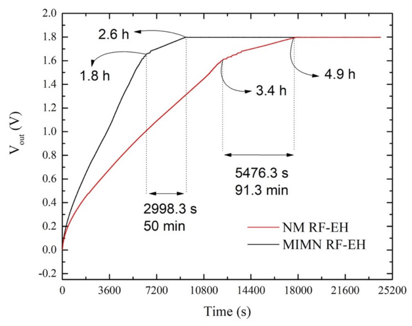
Figure 11.
Simulated efficiencies of a SMS7630 diode bridge rectifier where . is the measured input impedance of the EMS. The analysis has been done using ADS harmonic balance simulation to estimate the ratio between RF input power ( and the DC output power delivered to the load (.
Figure 11.
Simulated efficiencies of a SMS7630 diode bridge rectifier where . is the measured input impedance of the EMS. The analysis has been done using ADS harmonic balance simulation to estimate the ratio between RF input power ( and the DC output power delivered to the load (.
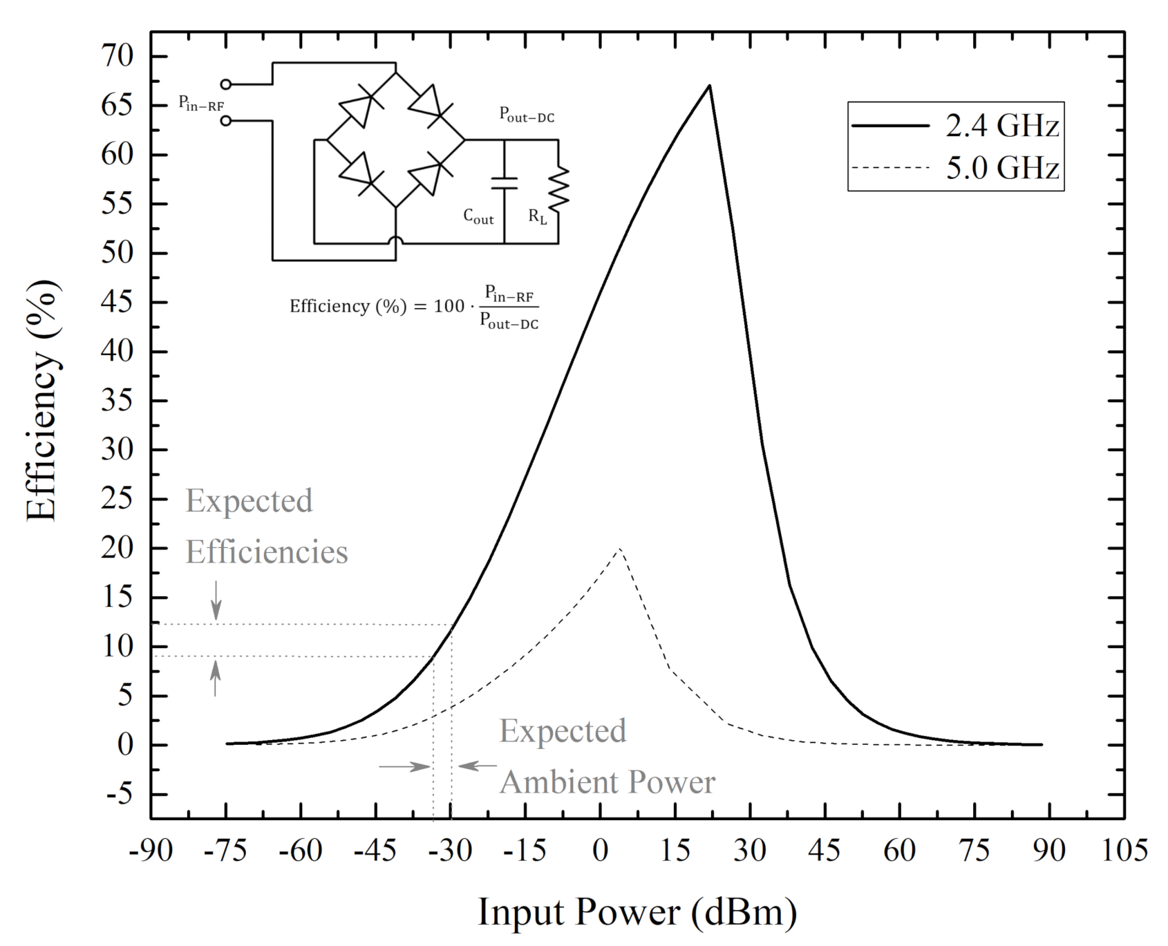
Figure 12.
Efficiencies of the bridge rectifier as a function of the load resistance at 2.4 GHz and 5 GHz (dash and continuous line, respectively) considering . Measured estimated efficiency of the bridge rectifier with the MIMN using the RF ambient power as input source.
Figure 12.
Efficiencies of the bridge rectifier as a function of the load resistance at 2.4 GHz and 5 GHz (dash and continuous line, respectively) considering . Measured estimated efficiency of the bridge rectifier with the MIMN using the RF ambient power as input source.
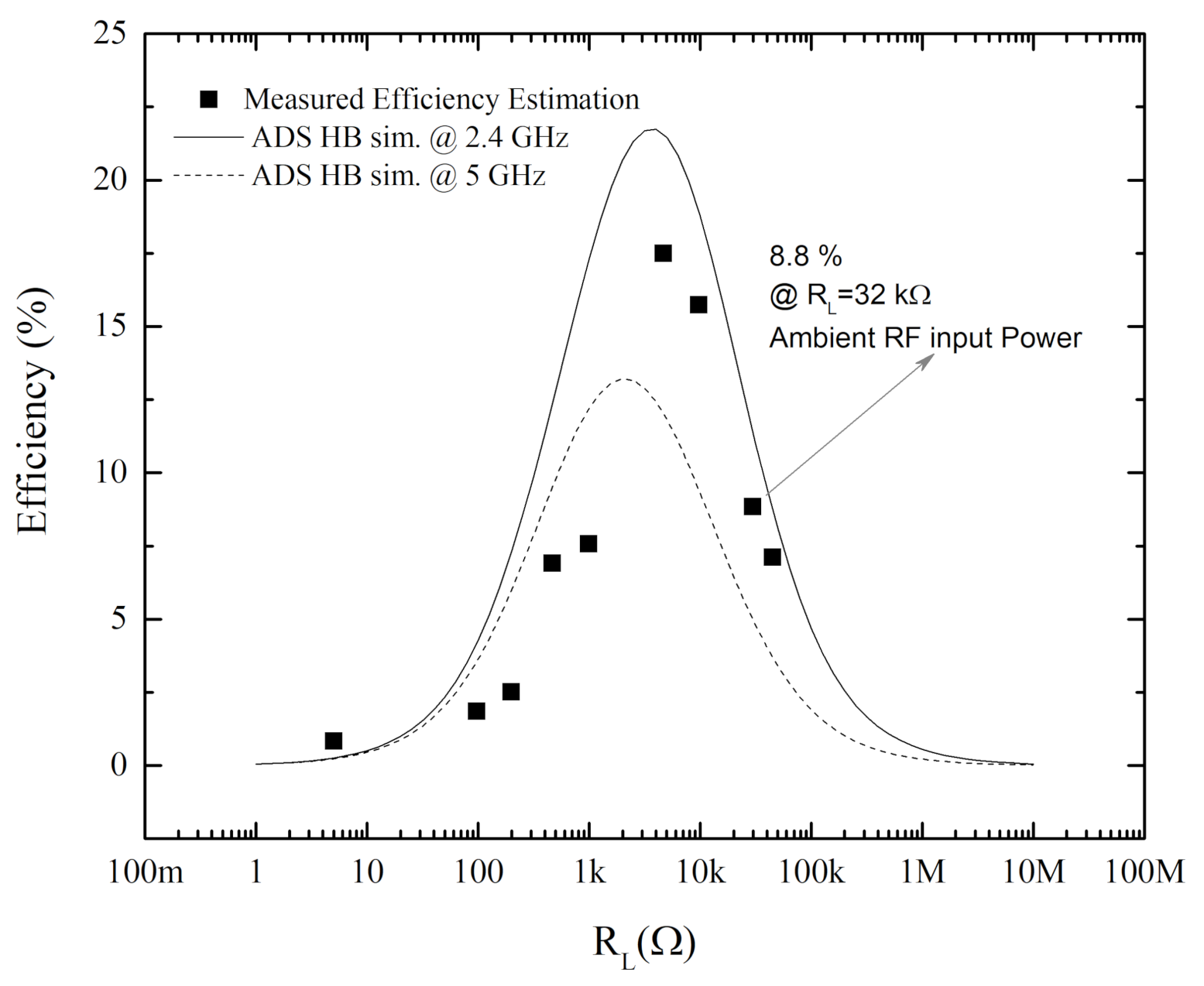
Figure 13.
Measured output voltages of the MIMN bridge rectifier system, for different output loads () using RF ambient as input power. Each point is labeled with the correspondent efficiency estimation.
Figure 13.
Measured output voltages of the MIMN bridge rectifier system, for different output loads () using RF ambient as input power. Each point is labeled with the correspondent efficiency estimation.


Table 1.
Summarizes some of the more recent efficiencies reported in the literature with similar systems to the proposed in this work.
Table 1.
Summarizes some of the more recent efficiencies reported in the literature with similar systems to the proposed in this work.
| References | Frequency (GHz) | Input Power | Diode Type | RF-to-DC Efficiency (%) | |
|---|---|---|---|---|---|
| [49] | 2.4 | −10 dBm | |||
| SMS7630 | 2.8 k | 10 | |||
| [50] | 2.4 | −20 dBm | SMS7630 | 5.3 k | 18 |
| [52] | 2.45 | −30 dBm | HSMS 2852 | 28 k | 10 |
| This Work | 2.4 | RF-Ambient (<−30 dBm) | SMS7630 | 32 k | 8.8 |
Publisher’s Note: MDPI stays neutral with regard to jurisdictional claims in published maps and institutional affiliations. |
© 2021 by the authors. Licensee MDPI, Basel, Switzerland. This article is an open access article distributed under the terms and conditions of the Creative Commons Attribution (CC BY) license (https://creativecommons.org/licenses/by/4.0/).
Share and Cite
MDPI and ACS Style
Coskuner, E.; Garcia-Garcia, J.J. Metamaterial Impedance Matching Network for Ambient RF-Energy Harvesting Operating at 2.4 GHz and 5 GHz. Electronics 2021, 10, 1196. https://doi.org/10.3390/electronics10101196
AMA Style
Coskuner E, Garcia-Garcia JJ. Metamaterial Impedance Matching Network for Ambient RF-Energy Harvesting Operating at 2.4 GHz and 5 GHz. Electronics. 2021; 10(10):1196. https://doi.org/10.3390/electronics10101196
Chicago/Turabian StyleCoskuner, Ertugrul, and Joan J. Garcia-Garcia. 2021. "Metamaterial Impedance Matching Network for Ambient RF-Energy Harvesting Operating at 2.4 GHz and 5 GHz" Electronics 10, no. 10: 1196. https://doi.org/10.3390/electronics10101196
Note that from the first issue of 2016, this journal uses article numbers instead of page numbers. See further details here.