Article

Compact Quad-Element High-Isolation Wideband MIMO Antenna for mm-Wave Applications

1
Electrical Engineering Department, City University of Science and Information Technology, Peshawar 25000, Pakistan
2
Research Institute for Microwave and Millimeter-Wave Studies (RIMMS), National University of Sciences and Technology (NUST), Islamabad 44000, Pakistan
3
Department of Physics, Islamia College, Peshawar 25000, Pakistan
4
Electronic Engineering Department, University of Rome “Tor Vergata”, Via del Politecnico 1, 00133 Rome, Italy
5
School of Engineering, Macquarie University, Macquarie Park, NSW 2109, Australia
*
Authors to whom correspondence should be addressed.
Electronics 2021, 10(11), 1300; https://doi.org/10.3390/electronics10111300
Submission received: 29 April 2021 / Revised: 27 May 2021 / Accepted: 28 May 2021 / Published: 29 May 2021
(This article belongs to the Special Issue Antennas for Wearable and Implantable Applications)

Abstract

:
This paper presents a multiple-input multiple-output (MIMO) antenna system for millimeter-wave 5G wireless communication services. The proposed MIMO configuration is composed of four antenna elements, where each antenna possesses an HP-shaped configuration that features simple configuration and excellent performance. The proposed MIMO design can operate at a very wideband of 36.83–40.0 GHz (measured). Furthermore, the proposed MIMO antenna attains a peak gain of 6.5 dB with a maximum element-isolation of −45 dB. Apart from this, the MIMO performance metrics such as envelope correlation coefficient (ECC), diversity gain, and channel capacity (CCL) are analyzed, which demonstrate good characteristics across the operating band. The proposed antenna radiates efficiently with a radiation efficiency of above 80% at the desired frequency band which makes it a potential contender for the upcoming communication applications. The proposed design simulations were performed in the computer simulation technology (CST) software, and measured results reveal good agreement with the simulated one.

1. Introduction

With the rapid development of mobile communication systems, different wireless systems like millimeter-wave Fifth Generation (5G) mobile networks and 60 GHz wireless fidelity (Wi-Fi) have been developed to meet the high data rate requirements of contemporary mobile communications and will be incorporated in modern devices in the future. In order to integrate various kinds of wireless systems in modern devices, and to achieve compact integration and good functionality, the components with a compact size and smaller antennas will become an important requirement. In this regard, a 37–40 GHz frequency band was considered a potential candidate for the next generation mobile networks [1]. This band of frequency provides a platform for higher bandwidths, high data rates and low latency [2].
The current wireless networks covering the lower portion from a few hundred megahertz to gigahertz of the frequency spectrum, is overcrowded and cannot fulfill a high data rate and bandwidth requirements for the future mobile communication systems. With the demands for higher data rate, bandwidth and reliable communication, the 5G wireless networks are directed to fulfill such a requirement. This system will enable the users to download a high-definition (HD) movie in a small segment of the time. Besides these, 5G networks will also help in the expansion of other technologies, i.e., smart cities, health care, autonomous vehicles and Internet of Things (IoT), this may even be helpful to develop the food and agriculture sector [3]. In a simple way, to meet these requirements for 5G, there is a need to move from lower to higher frequency bands of the existing radio frequency spectrum. The large portion of millimeter wave band ranging from 30 to 300 GHz is still idle and offers a large amount of spectrum which could potentially be utilized for 5G wireless communications [4]. A sufficient bandwidth of several GHz can be obtained at 38 GHz which has been recently investigated for 5G networks as the operating band [5]. Due to the higher data rate and bandwidth availability, this frequency band is of great interest in future mobile communication systems.
However, the utilization of these higher frequencies for future mobile broadband communication raises great challenges. The free space propagation is one of the challenges for these frequencies [6]; as the lower frequency signals have higher penetration power and can provide a coverage up to long distance. While the higher frequency signals possess lower penetration power due to which the signal becomes weaker while reaching from the transmitter to receiver and results in a less coverage area. To tackle this problem, array or multiple-input multiple-output (MIMO) antennas are crucial [7,8]. In the literature [9,10,11,12,13,14,15], several millimeter-wave 5G antennas have been reported. It is observed that some of them are single-port antennas and a few array antennas. As the single port antennas cannot be a solution to the problem discussed above, at the higher frequencies, while the array antennas possess high gain, they are still fed by a single port with the same channel capacity as that of single antennas. Furthermore, several antennas with MIMO configuration have also been observed in the literature [16,17,18,19,20,21], which can be a better solution to improve the signal quality while on the way from the transmitter to receiver and to ensure high data rate transmission with enhanced channel capacity and spectrum efficiency by exploiting multipath property without increasing the input power. Like in [16], the antenna with a 3-port configuration is presented with an overall volume of 55 × 110 × 1.6 mm 3 . The reported design operating band, i.e., 37.3–38.6 GHz lies in the millimeter-wave 5G dedicated band, i.e., 37–40 GHz. While the peak gain achieved is 4.6 dB with an isolation of −28 dB, it can be seen that the reported design holds a low bandwidth, low isolation and gain with such a large size. Similarly, a MIMO antenna with four elements is presented in [18]. The proposed antenna covers the frequency band from 36.68 to 37.32 GHz based on −10 dB criteria. Moreover, another four-port MIMO antenna was reported in [19] with an operational band ranging from 38.02 to 38.37 GHz and a good isolation of −34.8 dB. However, the low bandwidth of the proposed design makes it less competent for the millimeter wave 5G communication. Furthermore, in [20] a two-port MIMO antenna is observed which can operate at a band of 36.95–39.05 GHz with an isolation of −21 dB and gain of 1.83 dB. However, the reported design achieves a good bandwidth, however, the low isolation and gain constitute its limitations. Thus, concluding the discussion reveals that the MIMO antennas reported are either complex or large in structure, they are limited by their low bandwidth, low isolation and gain. In addition, in wireless communication, there is an another challenge—rain and atmosphere—due to which these higher frequencies become unfeasible [22]. In other words, fog, snowfall, and rain, etc., badly affect these frequencies; thus, electromagnetic (EM) waves face higher losses. However, the frequency band ranging from 37 to 40 GHz is less reactive and give minimum atmospheric attenuation. In [23], the rain and atmospheric attenuation experienced by various frequency bands ranging from 0 to 400 GHz were discussed. It was analyzed that the atmospheric attenuation was at least at the 37–40 GHz frequency band, and the maximum absorption was observed at 60, 120 and 190 GHz, etc.
Thus, considering the limitations discussed above, this paper presents a four-port MIMO configuration maintaining a geometrical simplicity and reasonable compactness for the millimeter-wave 5G wireless communication services—and operating in the most prominent frequency band, i.e., 37–40 GHz, dedicated to 5G communication applications. The proposed MIMO design is capable of covering the entire dedicated millimeter-wave 5G band by providing the operational bandwidth from 36.83 to 40 GHz. Each antenna element holds an HP-shaped configuration that features simple configuration and excellent performance. Furthermore, the diagonal position antenna elements are placed in an anti-parallel manner, while each element of the MIMO configuration is positioned orthogonally to one another to achieve the high isolation of −45 dB within the operating band. In addition, the ground surfaces of each antenna element are connected in MIMO configuration to achieve the same voltage in the antenna system.

2. Antenna Design and Analysis

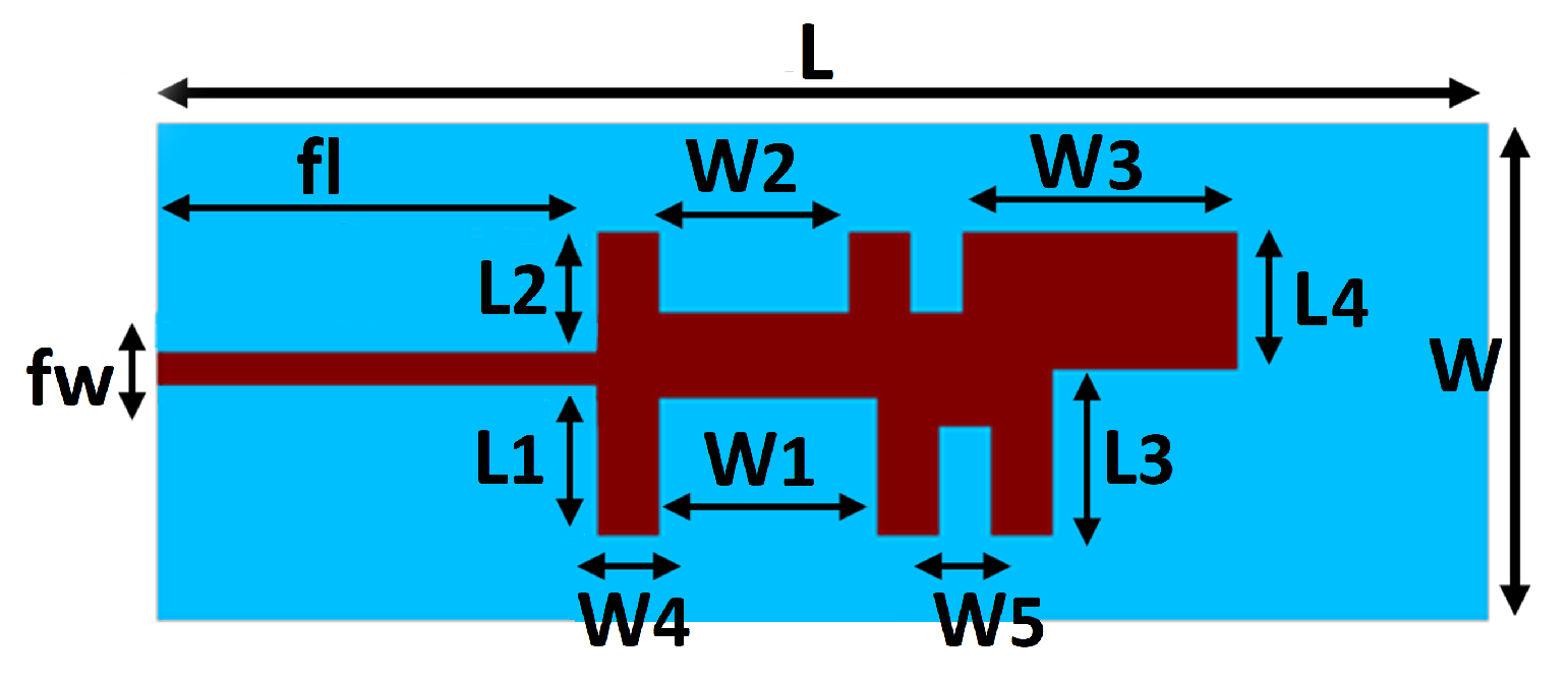
2.1. Antenna Element

Figure 1 shows the geometry of an antenna element which was later used for the proposed MIMO configuration. The Rogers RT-5880 substrate with a total volume of 23.7 × 8.8 × 0.51 mm 3 is used to back the radiating element. The copper material is utilized for the radiating element with a very even conductivity of 5.8 × 10 7 S/m. A finite ground plane of similar length and width as that of the substrate is used to back it, in order to achieve good performance by reducing the antenna radiated waves flow in the back direction. The various dimensions of the proposed antenna element are listed in Table 1. These dimensions are computed by using the familiar transmission line theory of the rectangular patch antenna [24].
The radiating patch is the modified version of the rectangular microstrip patch antenna as shown in Figure 2. The modifications were performed by introducing the slots in the radiating patch such that it adopts the HP shape. To obtain the resonant frequency in the range of 37–40 GHz (mm-wave 5G band), the dimension of the slots within the radiating patch of the intended design are wisely taken after a three steps design appraisal process as shown in Figure 2. In Figure 3, the reflection coefficients of the design steps are compared. In Step 0, without any modification in the rectangular patch, a non-satisfactory −10 dB bandwidth is observed at the desired frequency band. However, the successive improvements in the scattering parameter (reflection coefficient) and −10 dB bandwidth are perceived in Step 1 by introducing the H-shaped slot. As in Step 0 and 1, the improvement in the reflection coefficient magnitude or bandwidth was observed by varying the feeding position and slots insertion, respectively. While in Step 2 and 3, the feed position was maintained as the same, whereas slots insertion helps to improve the bandwidth and reflection coefficient magnitude, jointly. As in Step 2, P-shaped slot insertion shifts the resonant frequency due to the decrease in electrical length of the radiating element and yields a wideband response ranging from 37.5 to 40 GHz, while the further two slots’ insertion in the middle of H and P-shaped structure improve the S 11 from −18 to −33 dB in Step 3. The modifications (Step 1–3) in the rectangular patch evidence that they are strongly responsible in making their proposed antenna operating with a satisfactory bandwidth at the desired 38.51 GHz frequency band.

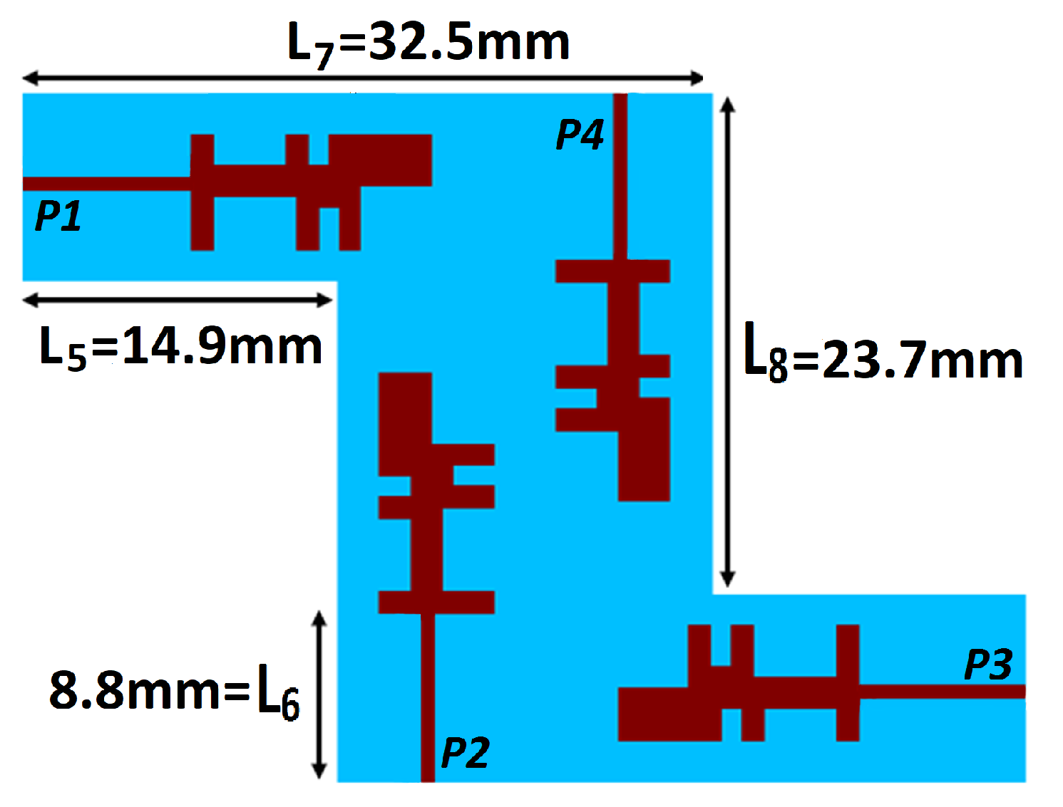
2.2. MIMO Antenna System

Figure 4 shows the geometry of the proposed MIMO antenna system. A single element was used to assemble a four-port MIMO antenna; whereas each antenna element was placed with a 90-degree phase difference, which results in the high isolation of above −25 dB across the operating bandwidth. Moreover, the placement of the diagonal position antenna elements in an anti-parallel manner was to reduce the mutual coupling among antenna elements. In addition, the ground surfaces of each antenna element were connected in a MIMO configuration to achieve the same voltage in the antenna system, whereas a total area of 23.7 mm × 8.8 mm was occupied by the antenna element.
Figure 5 shows the current distribution of the quad-port MIMO antenna at each port consecutively. It can be seen that the current is primarily intense at the edges of the HP-shaped portions of the radiating structure, which means that these are contributing the most to making the proposed structure resonate at the desired frequency band. Furthermore, the feedline of each antenna element holds a high current density. In addition, the coupling current was insignificant among the antenna elements due to their arrangement with a 90-degree phase difference and the anti-parallel position of a diagonal elements.

3. Results and Discussion
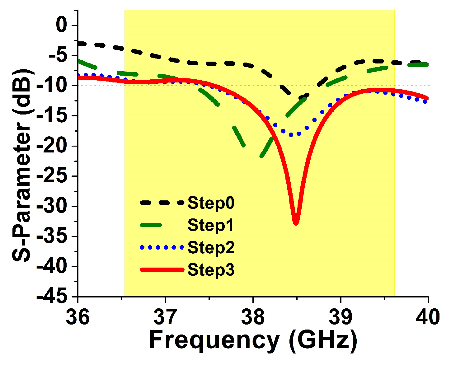
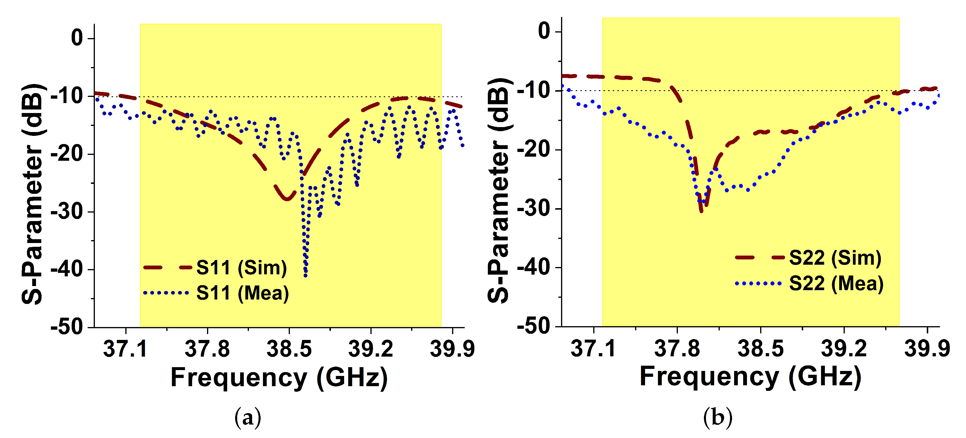
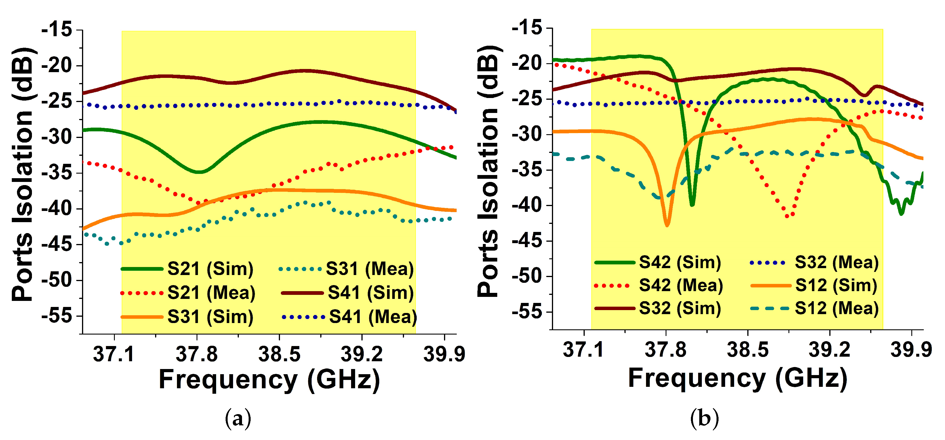
Simulated and measured results were compared and analyzed in this section. All the simulations of the proposed design were performed in computer simulation technology (CST) software. For the validation of simulated results, each antenna element of the MIMO system was fed by the 2.92 mm k-series connector, while the Agilent N5244A vector network analyzer (VNA) was utilized to observe the measured results. Furthermore, a 50 Ω load was used to terminate the unused ports while taking measurements, i.e., the reflection coefficient, transmission coefficient and radiation pattern—as shown in Figure 6.

3.1. S-Parameters

In Figure 7, a comparison between the measured and simulated reflection coefficient was presented. Because of the unavoidable use of cables throughout measurements and fabrication, losses may cause minor deviation in the resonant frequency, while the overall good resemblance of measured results with the simulated one is achieved. While the minor jumps in the port-1 S-parameter are observed due to the cable improper attachment with the connector by the tester while measurement. However, the measured bandwidth for both the antenna elements, i.e., one and two (P1 and P2) of the proposed MIMO system ranges from 36.86 to 40.0 GHz. Due to the symmetrical property, the reflection coefficient measurement is considered only across P1 and P2. Moreover, the isolation achieved was also greater than −25 dB among the antenna elements within the operating bandwidth—as shown in Figure 8.

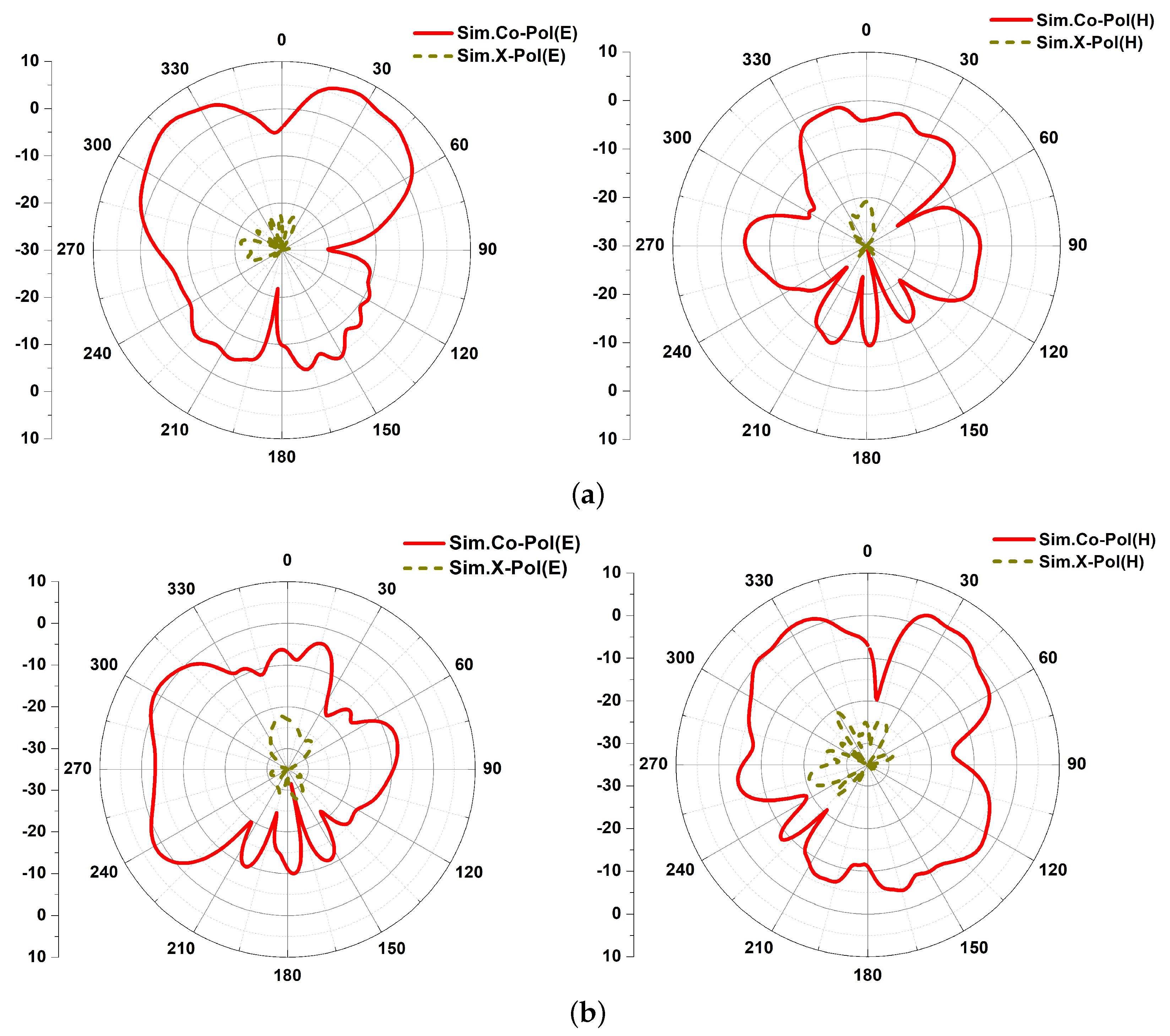
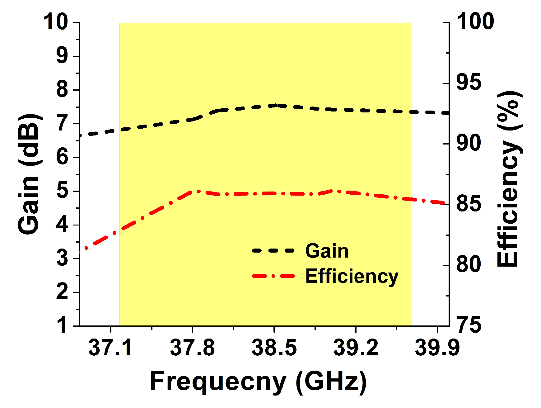
3.2. 2D Radiation Patterns (Far Field)

Figure 9 shows the simulated 2D radiation patterns (gain) at the 38.6 GHz frequency band in the E and H planes, respectively. The radiation patterns were observed for port-1 and port-2, which revealed the pattern diversity achieved by the proposed MIMO configuration due to the orthogonal arrangement of antenna elements. The gain and radiation efficiency achieved by the MIMO antenna are shown in Figure 10. The simulated peak gain of 7.6 dB with measured peak gain of 6.5 dB is observed, whereas the simulated radiation efficiency is noted to be 86%. In Table 2, the gain noted at a few frequency samples is listed while measuring radiation patterns in the anechoic chamber.

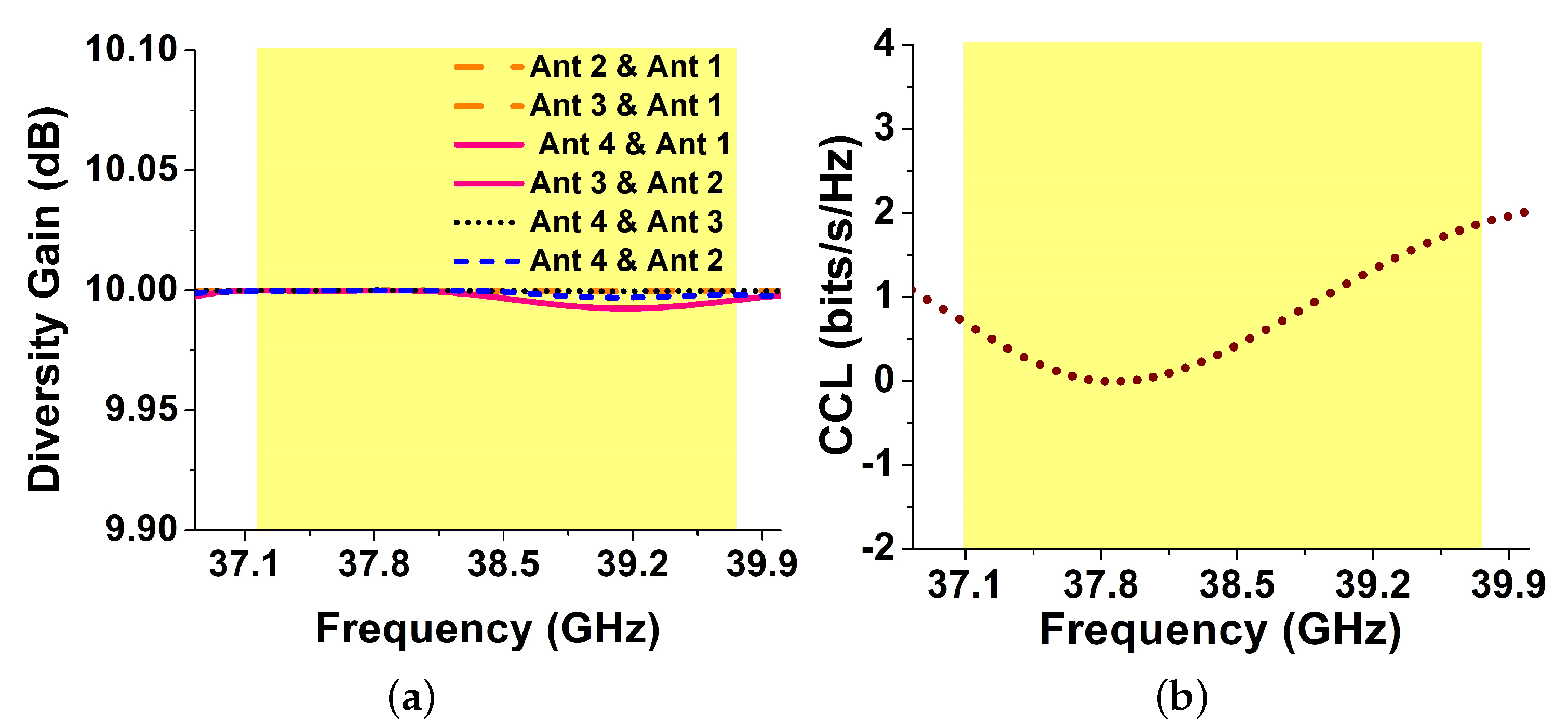
3.3. MIMO Performance Metrics

As the MIMO system is a combination of multiple antenna elements, mutual coupling analysis becomes important due to the placement of antennas in close proximity to one another. For this reason, in Figure 11, envelope correlation coefficient (ECC) being one of the key performance measures is analyzed. The lower value of ECC indicates a low mutual coupling and vice versa. The far-field formulation is used to compute the ECC for the proposed MIMO antenna system, given in [25]. Figure 11 illustrates ECC curves for the MIMO antenna which demonstrates the EEC value below 0.001 (<0.5 practical standard) for the desired operating frequency band; ensuring independent channel operation and optimal diversity performance.
Similarly, another key performance metric is diversity gain, which illustrates the amount of reduction in transmission power after the use of a diversity scheme without a performance loss for the MIMO antennas [26]. Figure 12a shows the diversity gain obtained for the proposed MIMO antenna. The value was found close to 10 dB (ideal value) across the desired frequency band due to the low ECC as shown in Figure 11. Likewise, another important factor in MIMO systems is channel capacity loss (CCL) which describes a loss in MIMO capacity due to the correlation in MIMO links [26]. Figure 12b shows a CCL for the MIMO antenna which is observed during the operating bandwidth (36.83–40.0 GHz) to be less than 0.6 bits/s/Hz, revealing the high throughput of the proposed MIMO antenna.
Table 3 presents a detailed performance comparison of the proposed antenna previously reported in the literature operating in the 37–40 GHz frequency band, as targeted in the present study. From the comparison, the proposed antenna advantages were observed over the previously reported antennas in terms of bandwidth, isolation, and size, etc. For example, in [16], a three-port MIMO antenna is reported having a large volume, low bandwidth and gain. Although, the MIMO antennas reported in [18,19,20] are observed with a compact size, their main limitations are their low bandwidth, low isolation, or gain. Likewise, antennas reported in [9,10,11,12,13,14,15] are lacking with MIMO features due to which the channel capacity is limited. The overall study concludes that the proposed antenna possessing an excellent MIMO functionality outperforms the existing antennas by covering the entire band, i.e., 37–40 GHz, dedicated to millimeter-wave 5G communication and providing a maximum isolation of −45 dB with an optimum gain and reasonable size.

4. Conclusions

In this paper, a novel MIMO antenna system is presented for millimeter-wave 5G applications. The proposed structure is composed of four antenna elements which are arranged in an orthogonal position to each other while diagonal elements are positioned in an anti-parallel manner. The proposed antenna covers the operation band from 36.83–40.0 GHz with a maximum element-isolation of −45 dB. Moreover, the proposed 5G antenna radiates efficiently with a radiation efficiency of more than 80%, while a peak gain of 6.5 dB was observed for the desired frequency band. In addition, the diversity performance of the proposed MIMO antenna system was found to be good according to the MIMO performance metrics, such as CCL, ECC and diversity gain. With good coherence between the simulated and measured results, high isolation among antenna elements, low channel capacity loss, low ECC, and satisfactory diversity gain, the proposed MIMO antenna constitutes a good candidate for 5G systems.

Author Contributions

Conceptualization, D.A.S. and M.A. (Muhammad Asif); methodology, D.A.S. and M.A. (Muhammad Asif); software, D.A.S. and N.S.; validation, M.I. and M.A. (Mohammad Alibakhshikenari); formal analysis, S.J. and M.A. (Mohammad Alibakhshikenari) and A.L.; investigation, M.A. (Muhammad Asif), N.S. and M.I.; resources, N.S. and E.L.; data curation, D.A.S.; writing—original draft preparation, D.A.S.; writing—review and editing, M.A. (Mohammad Alibakhshikenari), A.L. and E.L.; visualization, D.A.S., S.J. and M.A. (Mohammad Alibakhshikenari); supervision, M.A. (Muhammad Asif); project administration, M.A. (Mohammad Alibakhshikenari), A.L. and E.L.; and funding acquisition, M.A. (Mohammad Alibakhshikenari). All authors have read and agreed to the published version of the manuscript.

Funding

This work received no external funding.

Data Availability Statement

All data produced in the study are mentioned in the article.

Conflicts of Interest

The authors declare no conflict of interest.

References

  1. Hussain, N.; Jeong, M.; Abbas, A.; Kim, T.; Kim, N. A metasurface-based low-profile wideband circularly polarized patch antenna for 5G millimeter-wave systems. IEEE Access 2020, 8, 22127–22135. [Google Scholar] [CrossRef]
  2. Imran, D.; Farooqi, M.M.; Khattak, M.I.; Ullah, Z.; Khan, M.I.; Khattak, M.A.; Dar, H. Millimeter wave microstrip patch antenna for 5G mobile communication. In Proceedings of the 2018 International Conference on Engineering and Emerging Technologies (ICEET), Lahore, Pakistan, 22–23 February 2018; pp. 1–6. [Google Scholar]
  3. Vo, N.S.; Duong, T.Q.; Guizani, M.; Kortun, A. 5G optimized caching and downlink resource sharing for smart cities. IEEE Access 2018, 6, 31457–31468. [Google Scholar] [CrossRef]
  4. Khan, J.; Sehrai, D.A.; Khan, M.A.; Khan, H.A.; Ahmad, S.; Ahmad, S.; Ali, A.; Arif, A.; Memon, A.A.; Khan, S. Design and performance comparison of rotated Y-shaped antenna using different metamaterial surfaces for 5G mobile devices. Comput. Mater. Contin. 2019, 2, 409–420. [Google Scholar] [CrossRef]
  5. Nosrati, M.; Tavassolian, N. A single feed dual-band, linearly/circularly polarized cross-slot millimeter-wave antenna for future 5G networks. In Proceedings of the IEEE International Symposium on Antennas and Propagation and USNC/URSI National Radio Science Meeting, San Diego, CA, USA, 9–14 July 2017; pp. 2467–2468. [Google Scholar]
  6. Zhang, P.; Yang, B.; Yi, C.; Wang, H.; You, X. Measurement based 5G millimeter-wave propagation characterization in vegetated suburban macrocell environments. IEEE Trans. Antennas Propag. 2020, 68, 5556–5567. [Google Scholar] [CrossRef]
  7. Gan, Z.; Tu, Z.; Xie, Z. Millimeter wave high-isolated MIMO antenna with two opposite radiation directions. In Proceedings of the IEEE Asia-Pacific Microwave Conference (APMC), Kyoto, Japan, 6–9 November 2018; pp. 1010–1012. [Google Scholar]
  8. Yang, B.; Yu, Z.; Dong, Y.; Zhou, J.; Hong, W. Compact tapered slot antenna array for 5G millimeter-wave massive MIMO systems. IEEE Trans. Antennas Propag. 2017, 65, 6721–6727. [Google Scholar] [CrossRef]
  9. Seker, C.; Ozturk, T.; Guneser, M.T. A single band antenna design for future millimeter wave wireless communication at 38 GHz. Eur. J. Eng. Form. Sci. 2018, 2, 35–39. [Google Scholar]
  10. Ashraf, N.; Haraz, O.M.; Ali, M.M.; Ashraf, M.A.; Alshebili, S.A. Optimized broadband and dual-band printed slot antennas for future millimeter wave mobile communication. AEU Int. J. Electron. Commun. 2016, 70, 257–264. [Google Scholar] [CrossRef]
  11. Sharaf, M.; Zaki, A.; Hamad, R.; Omar, M. A novel dual-band (38/60 GHz) patch antenna for 5G mobile handsets. Sensors 2020, 20, 2540. [Google Scholar] [CrossRef] [PubMed]
  12. Yang, Y.; Sun, B.; Guo, J. A low-cost, single-layer, dual circularly polarized antenna for millimeter-wave applications. IEEE Antennas Wirel. Propag. Lett. 2019, 18, 651–654. [Google Scholar] [CrossRef]
  13. Yang, Y.; Sun, B.; Guo, J. A single-layer wideband circularly polarized antenna for millimeter-wave applications. IEEE Antennas Wirel. Propag. Lett. 2019, 68, 4925–4929. [Google Scholar] [CrossRef]
  14. Ojaroudiparchin, N.; Shen, M.; Zhang, S.; Pedersen, G. A switchable 3-D-coverage-phased array antenna package for 5G mobile terminals. IEEE Antennas Wirel. Propag. Lett. 2016, 15, 1747–1750. [Google Scholar] [CrossRef] [Green Version]
  15. Costa, I.F.; Cerqueira, A.; Spadoti, D.H.; Silva, L.G.; Ribeiro, J.A.; Barbin, S.E. Optically controlled reconfigurable antenna array for mm-wave applications. IEEE Antennas Wirel. Propag. Lett. 2017, 16, 2142–2145. [Google Scholar] [CrossRef] [Green Version]
  16. Marzouk, H.M.; Ahmed, M.I.; Shaalan, A.A. A novel dual-band 28/38 GHz AFSL MIMO antenna for 5G smartphone applications. J. Phys. Conf. Ser. 2020, 1447, 012025. [Google Scholar] [CrossRef]
  17. Iqbal, A.; Basir, A.; Smida, A.; Mallat, N.; Elfergani, I.; Rodriguez, J.; Kim, S. Electromagnetic bandgap backed millimeter-wave MIMO antenna for wearable applications. IEEE Access 2019, 7, 111135–111144. [Google Scholar] [CrossRef]
  18. Sunthari, P.M.; Veeramani, R. Multiband microstrip patch antenna for 5G wireless applications using MIMO techniques. In Proceedings of the IEEE First International Conference on Recent Advances in Aerospace Engineering (ICRAAE), Coimbatore, India, 3–4 March 2017; pp. 1–5. [Google Scholar]
  19. Tu, D.T.T.; Thang, N.G.; Ngoc, N.T.; Phuong, N.T.B.; Yem, V.V. 28/38 GHz dual-band MIMO antenna with low mutual coupling using novel round patch EBG cell for 5G applications. In Proceedings of the IEEE International Conference on Advanced Technologies for Communications (ATC), Quy Nhon, Vietnam, 18–20 October 2017; pp. 64–69. [Google Scholar]
  20. Hasan, M.; Bashir, S.; Chu, S. Dual band omnidirectional millimeter wave antenna for 5G communications. J. Electromagn. Waves Appl. 2019, 33, 1581–1590. [Google Scholar] [CrossRef]
  21. Hussain, N.; Jeong, M.; Park, J.; Kim, N. A broadband circularly polarized fabry-perot resonant antenna using a single-layered PRS for 5G MIMO applications. IEEE Access 2019, 7, 42897–42907. [Google Scholar] [CrossRef]
  22. Khan, J.; Sehrai, D.A.; Ali, U. Design of dual band 5G antenna array with SAR analysis for future mobile handsets. J. Electr. Eng. Technol. 2019, 14, 809–816. [Google Scholar] [CrossRef]
  23. Rangan, S.; Rappaport, T.S.; Erkip, E. Millimeter-wave cellular wireless networks: Potentials and challenges. Proc. IEEE 2014, 102, 366–385. [Google Scholar] [CrossRef] [Green Version]
  24. Balanis, C. Antenna Theory: Analysis and Design; John Wiley and Sons: Hoboken, NJ, USA, 2016. [Google Scholar]
  25. Kiani, S.H.; Altaf, A.; Abdullah, M.; Muhammad, F.; Shoaib, N.; Anjum, M.R.; Damaševičius, R.; Blažauskas, T. Eight element side edged framed MIMO antenna array for future 5G smart phones. Micromachines 2020, 11, 956. [Google Scholar] [CrossRef] [PubMed]
  26. Lin, I.K.; Jamaluddin, M.H.; Awang, A.; Selvaraju, R.; Dahri, M.H.; Yen, L.C.; Rahim, H.A. A triple band hybrid MIMO rectangular dielectric resonator antenna for LTE applications. IEEE Access 2019, 7, 122900–122913. [Google Scholar]
Figure 1. Geometry of the proposed antenna element.
Electronics 10 01300 g001
Figure 2. Proposed antenna element: design evaluation steps.
Electronics 10 01300 g002
Figure 3. Reflection coefficients for different antenna elements.
Electronics 10 01300 g003
Figure 4. Geometric layout of MIMO antenna system.
Electronics 10 01300 g004
Figure 5. Surface current distribution of the MIMO antenna system for: (a) port-1; (b) port-2.
Electronics 10 01300 g005
Figure 6. Proposed MIMO antenna under testing with a zoomed-in view.
Electronics 10 01300 g006
Figure 7. Reflection coefficient of 4-port MIMO antenna with respect to (a) P1; and (b) P2.
Electronics 10 01300 g007
Figure 8. 4-port MIMO antenna isolation performance with respect to (a) P1; and (b) supplementary ports.
Electronics 10 01300 g008
Figure 9. Radiation patterns for: (a) P1; and (b) P2.
Electronics 10 01300 g009
Figure 10. Gain and radiation efficiency of the proposed antenna system.
Electronics 10 01300 g010
Figure 11. ECC for the proposed 5G MIMO antenna.
Electronics 10 01300 g011
Figure 12. (a) DG; (b) CCL, for the proposed 5G MIMO antenna.
Electronics 10 01300 g012
Table 1. Geometric parameters of the proposed antenna element.
ParameterValue (mm)ParameterValue (mm)
W8.8L42.4
L23.7W14.0
fw0.51W23.5
fl7.92W34.85
L12.6W41.0
L22.3W51.0
L33.0
Table 2. Measured gain of the proposed antenna.
Freq. (GHz)Value (dB)
37.86.5
38.56.25
39.25.5
Table 3. Comparison of the proposed antenna performance with state-of-the-art works.
Ref.PortsOperat. BW.Gain (dB)Iso. (dB)Ant. Size (mm 3 )
[9]137.1–38.121.268 × 5.9 × 1.6
(1.0 × 0.73 × 0.2 λ 3 )
[11]137.16–38.366.515 × 25 × 0.25
(2.0 × 3.1 × 0.031 λ 3 )
[16]337.3–38.64.60−2855 × 110 × 1.6
(7.0 × 13.5 × 0.2 λ 3 )
[18]436.68–37.325.226.6 × 3.25 × 1.6
(3.2 × 0.4 × 0.2 λ 3 )
[19]438.02–38.375.72 *−34.819.25 × 26 × 0.79
(2.5 × 3.3 × 1.0 λ 3 )
[20]236.95–39.051.83−2126 × 14 × 0.38
(3.2 × 1.8 × 0.047 λ 3 )
Prop.436.83–40.06.5−4547.4 × 32.5 × 0.51
(5.2 × 4.05 × 0.063 λ 3 )
* Simulated; λ is the free space wavelength at the starting frequency of the overlap bandwidth.
Publisher’s Note: MDPI stays neutral with regard to jurisdictional claims in published maps and institutional affiliations.

