
Implementing a Gaze Tracking Algorithm for Improving Advanced Driver Assistance Systems


Computer Science and Engineering Department, Universidad Carlos III de Madrid, 28911 Leganés, Madrid, Spain
*
Author to whom correspondence should be addressed.
Electronics 2021, 10(12), 1480; https://doi.org/10.3390/electronics10121480
Submission received: 4 May 2021
/
Revised: 10 June 2021
/
Accepted: 14 June 2021
/
Published: 19 June 2021
(This article belongs to the Special Issue AI-Based Autonomous Driving System)
Abstract
:Car accidents are one of the top ten causes of death and are produced mainly by driver distractions. ADAS (Advanced Driver Assistance Systems) can warn the driver of dangerous scenarios, improving road safety, and reducing the number of traffic accidents. However, having a system that is continuously sounding alarms can be overwhelming or confusing or both, and can be counterproductive. Using the driver’s attention to build an efficient ADAS is the main contribution of this work. To obtain this “attention value” the use of a Gaze tracking is proposed. Driver’s gaze direction is a crucial factor in understanding fatal distractions, as well as discerning when it is necessary to warn the driver about risks on the road. In this paper, a real-time gaze tracking system is proposed as part of the development of an ADAS that obtains and communicates the driver’s gaze information. The developed ADAS uses gaze information to determine if the drivers are looking to the road with their full attention. This work gives a step ahead in the ADAS based on the driver, building an ADAS that warns the driver only in case of distraction. The gaze tracking system was implemented as a model-based system using a Kinect v2.0 sensor and was adjusted on a set-up environment and tested on a suitable-features driving simulation environment. The average obtained results are promising, having hit ratios between 96.37% and 81.84%.
1. Introduction
According to the World Health Organization (WHO), one of the top ten causes of death, globally, are road injuries produced by car accidents [1]. Also, the percentage of the earth’s population who die in these accidents has been growing in recent years. As reported by [2], more than 1.2 million deaths are the consequence of road traffic injuries, and the report shows that about 78% of car accidents are because of driver distractions.
Each year, the large number of car accidents comes at both tremendous human and economic cost [3]. Besides, as stated in [4,5] it is demonstrated that drivers are less likely (30–43%) to provoke collision-related damage when they have one or more passengers who can alert them. For this reason, both industrial and academic communities are interested in Advanced Driver Assistance Systems (ADAS) [6]. These systems aim to support the driver’s decision-making during the driving process, improving car safety, particularly, and road safety generally. At present, not only high-end cars incorporate ADAS, more and more mid-range cars, and low-end cars incorporate these systems too [7].
There is an extensive research field dedicated to the development of systems based on the analysis of the driver’s physical factors involved in traffic crashes. Regarding fatigue, it is demonstrated that driver fatigue can affect driving performance as much as alcohol. Thus, driver fatigue monitoring systems have been researched and developed over the last two decades. Examples are recent works [8], where a single-channel electroencephalographic device is used to monitor driver fatigue paying attention to the eye saccadic movement velocity as the reference index of fatigue, and [9], where the blinks of the driver are analyzed to determine fatigue levels using a standard USB camera.
However, there is a critical design issue when it comes to the warning or informing the driver using an automatic system. Research about the designing of warning systems shows that a careless design may influence negatively on the driver’s performance. On the one hand, it may increase their workload in the driving process, leading to a decrease in their situation awareness [10]. On the other hand, the excess of unnecessary information may be overwhelming, and it can lead to neglect and, finally, deactivation of the warning system [11].
Therefore, the general purpose of our research line is to propose, develop and test an agent-based alarm system that is designed as an intelligent Co-Driver, as a part of an ADAS, which only warns the driver when it is necessary, proposing an alarms hierarchy [12,13,14]. To do so, it is necessary to establish whether the driver is paying attention or not and for the ADAS to warn the driver in only two cases: if the driver is not paying attention, or if the situation is very dangerous. This is a completely new proposal in the state of the art. The proposed system is based on a camera-based eye tracker that uses the collected data for the detection of, among others, drowsiness or fatigue. In addition, this work develops non-proprietary software, which is part of a larger research project.
Advanced driver assistance systems (ADAS) are systems that help the driver to increase safety in the car and on the road as a consequence. In 1986, different European automotive companies and research institutes initiated the Prometheus project (Program for a European traffic of maximum efficiency and unprecedented safety), proposing solutions for traffic problems [15] Due to the lack of maturity of the technology in those years, it was necessary to wait until the last two decades in which this type of research has made significant progress. Research in recent years has focused on the development of ADAS capable of intervening in different ways to avoid potential hazards [15] and increase driver and vehicle safety [16]. Considering that 94% of traffic accidents are due to human error [17], this research in technological areas related to the development of increasingly powerful and comprehensive ADAS is essential.
Driver-centered ADAS are those that incorporate information obtained from the driver to provide assistance [18]. This type of driver information incorporated into the ADAS is essential, e.g., a lane departure detection system that does not integrate driver information cannot detect whether the vehicle departure is intentional or a mistake. Thus, if the driver is monitored and inattention or drowsiness is detected, it can be deduced that the vehicle departure is not intentional, and a warning to the driver can be triggered.
In this work, we go ahead and propose a non-intrusive real-time gaze tracking system for the driver that continuously determines where the driver is looking, providing the information needed about the driver’s attention by the ADAS. This gaze tracking system is a crucial piece that allows the ADAS and other in-vehicle warning systems to determine the driver’s need to be warned about a specific risk happening during the journey. The main idea is that the distraction of the drivers inferred by their visual area analysis leads to the actuation of warning systems.
The main contributions of this work are (a) the approach of using the driver’s attention to decide the ADAS activity, (b) the implementation of a parametric initialization method, thus avoiding to spend time on calibrating the visual system in which the user is asked to look at specific points of the screen to adjust the intrinsic parameters of the eye model, (c) besides, the integration of a gaze tracking system model in a driver-centered ADAS based on data fusion, to include in the model heterogeneous information, both from the environment and from the monitoring of the driver.
After this introduction, the remainder of this article is organized as follows. The next section provides an overview of the background and related work of driver inattention monitoring systems for intelligent vehicles and, especially, for gaze tracking systems. Section 3 describes the gaze tracking proposal with the explanation of the 3D eye model used to determine where the driver is looking, how this model is implemented and how it is used, and the experimental set-up of the system. Section 4 describes the different aspects of the experimental methods. Section 5 details the experimental results of the system in the environments where it is tested. Section 6 presents a discussion of the obtained results of the performed experiments. Finally, Section 7 presents the conclusions and future work guidelines.
2. Related Research
As stated before, driver inattention is the leading cause of car accidents, so, this subject is the purpose of many investigations in Computer Vision. In [19], there is an overview of driver inattention monitoring systems for intelligent vehicles and, in particular, of driver face monitoring systems [20].
Gaze tracking are the techniques that allows estimate the direction where an person is looking at [21] This problem, generally, can be faced through two different methods: appearance-based methods and model-based methods [22].
Appearance-based methods rely on eye appearance, i.e., assuming that similar eye appearances correspond to similar gaze positions. Thus, gaze estimation consists of extracting features from the eye images and learns a mapping function that relates to the eye image features and gaze’s positions. The mapping function is usually learned using different machine learning algorithms such as K-Nearest Neighbor [23,24,25], Random Forest [26,27], Support Vector Machines [28] or Artificial Neural Networks [29,30,31,32]. A current review of these methods can be found in [22,33]. Although appearance-based methods do not require any knowledge about human vision and they only need simple eye detection techniques, these methods require a large amount of data to learn the mapping function and consider only the gaze estimation problem in 2D, and this is an essential limitation in real problems such as driving. In addition, most of the existing appearance-based methods only work for a static head pose [34] which makes them unsuitable for the purpose of this paper.
Model-based methods rely on a geometric eye model representing the structure and function of the human visual system. These methods are known for their high accuracy because the eye model can simulate the human eyeball structure precisely. The gaze estimation is computed as the human brain does through the eye model, analyzing the human eye and head anatomy and critical components in the human visual system. The works in [35,36,37,38,39] are examples of model-based methods. Although model-based methods do require the necessary knowledge about human vision, these methods do not need any previous data. Besides, model-based methods consider the gaze estimation problem in 3D, so they allow free head movement during gaze tracking and obtaining the results not in a discretized way, but with a tridimensional gaze estimation vector.
There are commercial gaze tracking solutions which have accurate results as [40]. However, most of these systems require wearing physical devices to perform gaze tracking and cannot be applied in the driving task because it is too intrusive for the driver. Other systems such as Tobii EyeX [41] do not require users to wear any other device and would be a good candidate for the proposed application because they provide accuracy and resolution for estimating direction of gaze during driving. Therefore, these commercial solutions are not considered in this work, because, as previously mentioned, non-proprietary software is desired.
Recently Cazzato et al. [33] carried out an exhaustive study and comparison of the main gaze tracking methods reported in the literature. This comparison focuses on the accuracy achieved by each method, their advantages and disadvantages, as well as their reproducibility. Based on this study we have chosen different systems to compare them with the one used in this work. Table 1 shows the comparison of these systems according to the study carried out by [33].
So, Table 1 compiles a comparison of some gaze tracking systems, based on RGB cameras, RGBD, glasses and the one used in this work. As can be seen in Table 1, the system proposed by Wang and Ji in [42] describes a gaze estimation model based on 3D information gathered from a Kinect sensor. The main advantage of this method is its reproducibility. However, it requires that each person conduct a guided calibration process. Our approach is initially based on the Wang and Li model, nonetheless, it also includes a method for establishing the intrinsic parameters of the model regarding the human physiognomy, thus avoiding spending time on a calibration process. The method describe in [43] uses RGBD information to infer gaze using a geometric model that takes into account both eyes. It also requires a pre-calibration of the system to calculate the intersection point of the system. The main disadvantage is that it is a non-reproducible system. In [44], Al-Naser, et al. propose a glasses-based method that uses deep learning to predict the gaze in egocentric videos and test its transferability and adaptability to industrial scenarios. Its main advantage is its high accuracy, but it is a non-reproducible and intrusive system. The experimental evaluation on two publicly available datasets (GTEA-plus [45] and OSdataset [46]) revealed that, in terms of Average Angular Error, the results offered by this system are similar or better than those obtained by some state-of- the-art methods. One of the main limitations of this system is its difficulty to deal with sudden head motion. In addition, its implementation is not open source, so it is a non-reproducible system. In [47], Liu et al., propose a system to predict gaze differences between two eye input images of the same subject. This is an attempt to introduce subject-specific calibration images to improve the performance of end-to-end systems. The system processes a high number of fps, is cheap, but does not allow working with 3D data and requires prior calibration of each user. These characteristics do not make it suitable for the purpose of our work. In [48], the gaze is inferred using two different CNNs to model head pose and eyeball movements, respectively. The gaze prediction is extracted after aggregating the two information sources by introducing a “gaze transformation layer”. This layer encodes the transformation between the gaze vector in the head and camera coordinate system without introducing any additional parameters that can be learned.
After the analysis carried out, it can be concluded that the implemented system, based on [42] and with the incorporated modifications, is a suitable approach for the driving problem addressed in this paper.
In recent years, there have been many advances in the field of ADAS. In [49], Hagl and Kouabenan examined whether the use of ADAS can lead to driver overconfidence and whether this overconfidence can have consequences on road safety. One aspect not addressed in the literature is whether the activation of certain alerts may be counterproductive for the driver. So, for example, in the recent works of [50,51] the driver is alerted to dangerous situations (forward-collision or lane departure), but no analysis of the potential adverse effects due to warning activation is performed. However, it has been shown that excessive and/or unnecessary alerts from an ADAS can lead to the diver ignoring or turning off the system [52]. In a previous work [14], this problem is solved by including in the ADAS reasoning process, some information about the attention of the driver through the gaze tracking system. In this way, the driver is warned only when it is necessary: When they are not attentive or when they are attentive, but the situation is very critical, as illustrated in Figure 1.
In this work, a model-based gaze tracking system is implemented using a Microsoft Kinect v2.0 sensor (Microsoft, Redmond, WA, USA). Microsoft Kinect v2.0 is a low-cost device with two optical sensors (RGB and IR cameras), whose distributable software distribution incorporates a biometric API library. It has been considered a suitable sensor for the simulator, and its feasibility has been demonstrated in previous works. In addition to the advantages detailed above, this kind of method can be easily reproduced and is more general without having a large amount of previous data. The Kinect sensor is used as a system viability study, capable of being replaced by another more accurate sensor once the feasibility is validated.
This approach is mainly based on [42] (nomenclature and notation included), where a Kinect camera is used too. Nevertheless, the method of obtaining the parameters of the model is entirely different. In this study, a personalized calibration framework was proposed and basically, it relies on choosing the subject-dependent eye parameter that minimizes the distance between the estimated point where the user is looking on the screen and some pre-defined point shown on the screen. Besides, our system is not only tested on a screen, a controlled environment with ideal conditions. Finally, the gaze tracking system is integrated with our ADAS project and is tested and analyzed in a driving simulator [53] with real subjects during the driving task. The designed scenarios in the driving simulator will be described in Section 4.
3. Proposed Eye Tracking Model
3.1. Gaze Tracking Approach
As mentioned in Section 2, in this work, a model-based estimation method is used. Thus, the first thing is the construction of a 3D eye model that resembles human vision and its eye gaze, based on [42], and illustrated in Figure 2.
The eyeball and the cornea are represented as two spheres intersecting with each other. The main parameters of the eyeball sphere are the eyeball center (e), the eyeball radius (re), the pupil center (p) and the fovea. The main parameters of the cornea sphere are the cornea center (c) and the distance between both cornea and eyeball centers (rce).
The optical axis (No) is the line that connects the eyeball center (e), the cornea center (c) and the pupil center (p). However, the real gaze direction comes from the visual axis (Nv), which is the line that connects the fovea and the cornea center and is a deviation of the optical axis (No). That is because the fovea is a small depression in the retina of the eye, where visual acuity is the highest. The angle between these two axes is a fixed angle called kappa, and it is typically represented as a two-dimensional vector [α, β].
It should be noted that there are two different coordinate systems: the camera coordinate system and the head coordinate system. The camera coordinate system has its origin point (0,0,0) at the position of the camera, while the head coordinate system has its origin point (0,0,0) at the center of the head. This way, the eyeball center position can be represented in the camera coordinate system (e) or as an offset vector in head coordinates (Vhe).
In order to map a point from one coordinate system to another, the rotation R and translation T of the head relative to the camera coordinate system are required. Thus, the same point in camera coordinates zc and head coordinates system zh are mapped as given in (1):
3.2. Implementation of the Model
The main objective of this work is to determine the direction of the driver’s gaze, use this information as an indicator of their attention and thus take it into account in the development of the ADAS. In a future work, it is recommended a better camera to be used in a real car because more accuracy and better resolution will be needed. So, in this work, following the [42] proposal, we use a Microsoft Kinect v2.0 sensor to capture the images and perform the gaze tracking process. Figure 3 depicts the distinct steps required for the obtention of the gaze from an input image.
After face detection using Kinect libraries implemented with this specific purpose, this process consists of three main steps:
- Gathering the required information
- Performing the corresponding spatial calculations
- Calculating the Point of Regard (PoR)
The first two steps correspond with the driver’s information obtaining and using the mathematical model to detect where the driver is looking. The last step consists of discretizing this outcome to determine the specific gaze value that can be used in the given context (e.g., a screen, a driving simulator, a real car). This last step can be adapted to be used in any system.
3.2.1. Gathering the Required Information
This first step involves obtaining the pupil center in the camera coordinates system (p), and head translation (T) and head rotation (R) described as 3D matrices relative to the camera. In this step, it is necessary to make sure that the gaze tracking system has the parameters that relate to the person (θ). These are, therefore, the necessary parameters that must be obtained.
For the information about the head position relative to the camera, it can be easily obtained by using the Kinect Runtime API and calculating the corresponding transformations and changes of measuring units. However, there is no function for retrieving the pupil center in real time. For solving this issue, in [42] the pupil center was manually located during the calibration process, collecting enough samples for performing estimations using RANSAC.
Thus, a new pupil detection method is implemented. This method uses the Emgu CV library [57] for image processing, putting each frame captured by the camera through the following process, composed by 1 (EROI) and 2 (pupil center coordinates) steps described below.
- 1.
- Extraction of the Eye Region of Interest (EROI)
First, the process of extracting the Eye Region of Interest (EROI) selected the area which surrounds one of the eyes, depending on the position of the driver’s head (it is assumed that the other eye will behave similarly).
The EROI is obtained by the KinectFace library. For that, a face alignment method is used for constructing the 3D mesh of the face composed by a set of 3D points. Common facial points are indexed in the 3D in such a way that the distinct face features are easily determined. Therefore, left and right EROI are rectangles defined by 4-tuple that contains the coordinate (x, y) of its left corner and, its width and height, thereby specifying its dimension as follows (2) and (3):
Where eic is the eye inner corner point, emt is the eye middle top point, eoc is the eye outer point and emb is the eye middle bottom point. The notation of these points includes the prefix l and r corresponding to the left and right eye respectively. The choice between EROIr and EROIl depends on the yaw angle of the driver’s head relative to the Kinect device. Consequently, if the driver’s head is turned to the right relative to the camera, the left eye is processed because of the right eye partial or total occlusion. So, if the driver’s head is turned to the left relative to the camera, the right eye is processed for the same reason.
- 2.
- Estimation of the Pupil Center Coordinates.
Once the EROI is set, the resulting image undergoes a series of changes. The detection of pupil consists in a segmentation process composed by several operations in such a way that pupil will be located in the image. First, it is converted to grayscale and then passed through a white-and-black filter, which sets to white the darkest parts of the image (the iris and pupil) above a specified threshold and leaves the remainder in black. Finally, an erode filter is used to remove specific pixels from the edges of the white part of the image, and the mass center of the white pixels is calculated.
This calculation of the mass center will return the coordinates of the center of the pupil in the ROI, which can be translated to the coordinates in the complete image to obtain the pupil center in the camera coordinates system. Figure 4. Illustrates the entire segmentation process described above.
3.2.2. Performing the Corresponding Spatial Calculations
Once all the needed information {p, R, T, θ} is gathered (p, R, T is calculated for each frame), the gaze direction vector is calculated using the 3D eye model described in Section 3.1.
From these parameters, the eyeball center e can be calculated as (4):
Then, having the eyeball center e and the pupil center p, optical axis No can be calculated as (5):
As the optical axis, No passes through the cornea center, and it can be calculated as (6):
The unit vector of the optical axis No can also be expressed as two angles Φ and γ (7):
Thus, adding the deviation kappa angle, visual axis Nv can be calculated as (8):
The resulting gaze direction vector is a vector that follows the visual axis (Nv), in the camera coordinates system. Note that at this point, we have a gaze estimation vector in a non-discretized way.
Making a calibration of the parameters that depend on the person is recommended, to adjust the model and the system to the driver that is going to perform the driving task. This way, in only a few seconds at the beginning of the process, the 3D model of the eye is modified to resemble the visual system of the driver. However, this work is a continuous improvement project whose first life cycle aims to integrate physical aspects of driver monitoring in the ADAS reasoning and, to prove the viability of the use of a gaze tracking system applying an initialization process based on the average features of human beings, just as mentioned in Section 3.1. Gaze Tracking Approach. Although the calibration process provides an overall better accuracy, the proposed initialization method reduces the required time for system adjustment during experiment sessions.
3.2.3. Calculating the Point of Regard
The PoR can be calculated in each moment by intersecting the gaze direction line with a concrete surface. It is important to note that this surface must be expressed in the camera coordinates system. The gaze direction line can be easily determined using the previously calculated gaze estimation vector and the cornea center (c) point. Then, the equation of the gaze direction line results as follows (slope-intercept form), where t is a parameter:
Figure 5 shows an example of model results using the computer display to define the surface that intersects with the gaze direction line. This self-image captured during the running of gaze tracking remarks the previously exposed model aspects as colored circles. The green circle (A) indicates the estimation of pupil center (p) as result of the image segmentation process. Two white circles (B) are the extreme points of the unit vector which define the gaze direction line in the 2D coordinate space. These points are almost overlapped due to the projection over the image plane. The blue circle is the PoR using the plane described by the screen as intersection surface with the graze direction line (C). The red point is a reference point that indicates the center of the image (D).
However, due to the definition of the problem, in this work, the surrounding space of the driver is discretized to establish the possible zones within the car where he/she can look in each moment.
In a vehicle, the driver’s field-of-view is not distributed symmetrically along the yaw axis because the driver is sat on the left (or right) side. Consequently, the gaze patterns and head movement required for inspecting the three view mirrors are completely different. The inspection of the rear-view mirror requires looking slightly to the right, nonetheless, it can consider that gaze is focused on the center. Focusing the gaze on the left-side mirror implies the pupil rotation and the peripheral vision mostly, whereas the inspection of the right-side mirror involves turning the head as well.
Assuming the gaze patterns exposed above, the gaze areas were set, thus dividing the complete display width consist of three screens accordingly.
In this first approach, the possible gaze values are Left, Front-Left, Front, Front-Right, and Right. These are some of the values that are required in the Agent-based ADAS and are contained in the ontology defined in the project, and used in the driving simulator. Therefore, the surrounding space of the driver is divided into these 5 zones, where each zone is defined as follows:
- Front. The driver is looking ahead through the car’s windshield and it includes the inspection of the rear-view mirror.
- Front-Left. Driver is looking to the left-side of the windshield, also looking indirectly ahead by their peripheral vision. In this case, the driver focuses their visual attention on dynamic environment entities such as pedestrians and vehicles that are moving transversely to the vehicle’s trajectory. Therefore, while the drivers are inspecting one side, they are not aware of the other side (right).
- Front-Right. Analogous to the previous case, the driver is looking to the right side of the windshield, also looking indirectly ahead using their peripheral vision. Consequently, while drivers are inspecting the events that occur in this area, they are not aware of the other side (left).
- Left. The driver’s vision is focused on inspecting the left-side rear mirror; thus, the pupil rotates towards the lateral canthus of the eye, so they are not aware of what is happening ahead, on the front of the car and on the right side.
- Right. Inversely to the previous case, the driver’s vision is focused on inspecting the right-side rear mirror that requires the pupil rotation towards the outer eye canthus and even turning their head. Therefore, they are not aware of what is happening ahead, on the front of the car, or on the left side.
The five virtual surfaces are modeled in the camera coordinates system. Specifically, five planes are defined in front of the driver, as shown in Figure 6. In this picture, it can be seen the three screens of the driving simulator and one plane for each gaze value from the driver’s perspective.
As can be seen in Figure 6, the Front gaze value is the part of the windshield that corresponds to the front of the car. Front-Left and Front-Right gaze values are next to this zone, and they represent the sides of the front of the vehicle, just before the rear-view mirrors. It can be observed that the left side is smaller than the right side, and this is because the driver is located in the front left seat, so the left area is smaller than the right area. Finally, Left and Right gaze values are extended through both sides to a defined maximum area of view. If this area is exceeded, then the gaze value is labeled with “-” (unknown).
In some of the frames captured by the camera, the gaze system is not able to recognize the user (e.g., because the user covers their face with their hand, looks at a non-defined gaze zone such as downwards or the system cannot detect him/her), giving the output “-“. These frames are, thus, discarded and labeled as “Unknown”.
Therefore, the gaze direction of the driver in each moment is defined as the intersection of his/her gaze direction line and one of these described virtual surfaces. Depending on which plane is intersected, so will be the value of the PoR.
4. Experimental Design
4.1. Data Acquisition on Set-Up Environment
As previously mentioned, the sensor used in this work is the Microsoft Kinect v2.0 camera. The gaze tracking system was first adjusted in this environment and after was tested in the driving simulation environment. The gaze values described in Section 3.2 were the same in both evaluation environments. Nevertheless, for the set-up environment, the five defined planes were readjusted to smaller proportions for fitting in this scope.
This environment, in which the gaze tracking system is adjusted, consists of a personal computer in a laboratory, where the distance and location to the Kinect sensor and the light conditions are ideal. The sensor is located centered, under the screen. The distance between the subject and the camera is approximately 60 cm (depending on the person). Finally, the light conditions are clear, not producing shadows or reflections on the face of the subject. This first evaluation is made to allow the adjustments of the proposal and prove that the approach is working correctly in a controlled environment.
This set-up process required that the user looks at the five defined zones for the same amount of time, for five minutes, while he/she was being recorded at a frame rate of 30 frames per second (fps). A single video had, thus, a total of 9000 frames.
4.2. Experiment Designing in Driving Simulator Environment
4.2.1. Integration of Gaze Area in the ADAS Based on Data Fusion
The gaze estimator presented in this paper is a subsystem part of a fusion data based ADAS. Figure 7 shows in general terms the three subsystems which compose this ADAS and how the estimation of the gaze area is integrated in the system model.
As can be observed, STISIM driving simulator [53] is the master subsystem because the execution of a driving scenario is the starting point for the communication of all subsystems. Moreover, the API component allows the deployment of new features like the inclusion of virtual sensors (e.g., distance, object detection) and the inclusion of messages on the simulator’s display (e.g., alarms, distances). In addition, it allows obtaining driving data such as reaction time to driving events, the angle of rotation of the steering wheel at each moment or the activation level of each of the pedals of the car: clutch, throttle, and brake.
It should be noted the importance of the ADAS Manager. This middleware component orchestrates the interaction processes across the integrated subsystems, thereby holding the synchronization of this distributed system and providing it with the conception of a unique system. Mainly, it has two purposes. The first purpose is to manage and compose ontology instances from data about the relevant aspects of the current driving scene, including the environment information and driver monitoring aspects such as the gaze area estimation presented in this work. Second is to scatter these produced instances to the intelligent agents’ system and manage their responses, in such a way that a signal is transmitted to the virtual HCI for raising a visual/sound alarm.
Intelligent agents’ system is the data analysis core of this data fusion based ADAS where driving scenes are classified as potential hazards or not. In this case, agents are implemented as rule-based models, being able to identify five distinct hazards hierarchically [58].
Moreover, the diagram also illustrates the communication interfaces that each system either provides for connectivity with other systems or requires for its functioning. Details about communication protocols and the modeling of ADAS reasoner were widely explained in [58].
4.2.2. Vision System Configuration
Here, the Kinect sensor was located centered, above the screen. However, the distance between the camera and the subject was higher (110 cm) than in the first experimental process. Although the light conditions could be practically the same, the angle which is formed by the sensor and the person (approximately 35°) causes shadows and reflections in the driver’s face, particularly in the eye sockets, making this environment more realistic. This evaluation was made to observe how the system behaved in more restrictive conditions, and to prove the viability of the system.
4.2.3. Driving Scenario Designing
STISIM drive were used for defining personalized scenarios within the simulator. This experiment consisted of the performance of the driving task by the different subjects in a driving simulator while being filmed, and their gaze was monitored at the same time. This time, the drivers did not look at the five gaze zones the same amount of time, because most of the remarkable events took place in the front side or the right side of the vehicle (e.g., parked cars that start their march or crossing pedestrians), as in real driving.
Two complex scenarios were used to perform the driving task in the experiments. These scenarios, besides including normal driving periods, have road situations that are extreme and force the driver to decide in a short time. The designed scenarios are described in [59]. The simulation scenarios used for the experimental trials contemplate risky situations which are commonly associated with driving in urban areas. The main design process requirement is to present driving conditions in which the driver’s visual attention over roadsides will be crucial.
The methodology for describing scenarios based on the theatre metaphor allows to detail all the concerning aspects in the design process of driving trails [58]. Therefore, a scene represents a situation in a specific location with a particular scenery and, and which involves actors whose participation directly affects the driver’s behavior. The scenario is composed of a sequence of four kind scenes described as follows. For instance, one of these scenes takes place in both residential and commercial areas. On these locations pedestrians circulate and it often has parked vehicles on both sides of the roadway, narrowing the range of the driver’s visual field. Then, the scene consists of a pedestrian who walks across the road. In this case, the driver’s vision and the braking reaction time are a handicap to deal with the scene successfully without running over the pedestrian (see Figure 8).
With the purpose of assessing the gaze tracking model, the resulting videos from the experimental season were visually analyzed frame by frame and the gaze area where the participants were looking at were manually labelled. ViperGT software [60] were utilized for conducting this process. This image and video labelling tool allow to create personized XML schemes which hold a wide sort of labels, including text labels. Figure 9 shows the interface of ViperGT during the labelling process and how the gaze area is assigned for each frame. As result of the set of instances are paired labelled, one corresponding to proposed model estimation, and the other as result of this ground-truth process.
4.3. Experiment Protocol
For the data acquisition of set-up environment, the execution of gaze tracking was recorded in video. These videos were later used to perform a ground truth labeling process, which is manual, costly, and time-consuming. Then, having both the output of the gaze tracking system and the labeled video of the experiment, the results of the experiment were processed to assess the accuracy of the model in this controlled environment.
The driving simulation environment consists of a driving simulation system where the gaze tracking system was integrated and deployed. Thus, the gaze tracking system is synchronized with the driving simulation environment in such a way that it can communicate where the driver is looking at each moment of the driving task.
Totally, 10 non-visual defect men and women with ages from 21 to 32 (24.6 ± 3.13), with driving experience of more than 2 years and, between 6000 and 15,000 km/year, performed the driving trial. The experiment consists of two sessions performed on separate days. However, only second driving sessions in which ADAS system supported to the driver when faced with the hazardous events were recorded in video. Regarding the assessment of the proposed gaze tracking, some recorded sessions were manually labeled to determine the system accuracy in this domain. It is important to note that all subjects gave their informed consent for inclusion before their participation in the study. The study was conducted following the Declaration of Helsinki, and the protocol followed the recommendations of the Ethics Committee of the institution [61].
5. Results
5.1. Set-Up Environment
The experiments accomplished in the set-up environment are the experimental setup that allows the adjustment of the system. 18,000 frames of two people are evaluated to prove this first approach in this set-up environment. The ages of these two subjects are 23 and 31 years, with different kinds of skin tones, and with no visual defects.
Table 2 shows the resulting confusion matrix, as well as other additional results, explained as follows:
- Unknownratio: a fraction of the total frames that are not recognized.
- Hit ratio (absolute): hit ratio without discarding the not recognized frames.
- Hit ratio (relative): hit ratio discarding the not recognized frames.
- Mean error: mean error discarding not recognized frames. Error is given by calculating the distance among the different classes (10):
In this experiment, it is observed that the unknown ratio is meager, less than 1% of the total frames. Also, the total relative hit ratio is 96.37%, and the mean error is 3.63%. It is noted that the mean error corresponds with the percentage of fails in the prediction since the maximum distance among the wrongly predicted frames is 1.
Regarding the confusion matrix, it is observed that the hit ratio per class is also high, from 93.09% to 100%. Front-Left and Front-Right classes are worse predicted than Left and Right classes because they are intermediate, so they have more probabilities of failing. However, Front class is better predicted, since the camera has a better view of the user in this case.
5.2. Driving Simulator Environment
Figure 10 shows the ADAS actuation while the driver’s attention was focused on the front and a pedestrian crosses the roadway suddenly. In this experiment, five minutes of video were randomly extracted from the complete driving tasks with the purpose of labelling the gaze area manually. Due to this particular process of manually labelling means a costly effort, 3 out of 10 participants were randomly selected for it. As a result, the ground-truth of the gaze area was obtained from 27,000 frames.
Table 3 shows the resulting confusion matrix and other additional results.
As can be observed, the results concerning the driving experiment show a higher rate of unidentified gaze area (11.16%) than exhibited in controlled conditions (0.79%) because of the differences between both vision system configurations and environmental conditions. Thus, the total relative hit ratio is 81.84%. Nevertheless, considering the environmental conditions, this hit ratio is good enough given the objective of the present work, as detailed below in Section 6, primarily because in the zones where, mainly, risky situations happen. For example, if in a period of 3 s before a dangerous situation occurs, more than 8 out of 10 frames will be detected before, or in other words, 75 frames out of 90 that are processed, it is assured that the alarm will be triggered and will warn the driver.
The mean error obtained now is 19.14%. Now, it does not correspond with the percentage of fails in the prediction, since now the distance among classes is greater than 1 in some cases (e.g., the distance between Left and Front is 2, see Figure 5).
Regarding the confusion matrix, it is observed that the hit ratio per class now is higher in the Front gaze value, with 93.05%. The front gaze is the majority class because the driver is looking ahead most of the time. The rest of the classes follow the same pattern as in the controlled environment, Left and Right classes were better predicted than Front-Left and Front-Right classes. As stated before, extreme classes (Left and Right) had fewer frames, and there were more frames on the right side than on the left side.
The environmental conditions in the driving simulation environment affect the accuracy of all classes. However, the Front class is just slightly reduced. Therefore, we can conclude that these conditions influence the side gaze values substantially. The position of the head and the features of the face produce light variations like shadows and reflections and are factors which alter the performance of the gaze tracking system.
6. Discussion
The gaze tracking system based on [42] was evaluated in two different kinds of environments. Due to the conditions of each environment, the results obtained in the set-up environment were better than the obtained in the driving simulation environment.
However, the objective of our ADAS project is ultimately to have it incorporated in a real car. This objective makes it essential that the environment have to be as realistic as possible, as in the driving simulation environment by now. Therefore, after this validation of the viability of the ADAS with the gaze tracking system, the camera must be replaced with another sensor with higher resolution, as well as future works must be done as detailed in Section 7.
The resulting unknown ratio of 11.16% means that three frames are lost each second. This value is experimentally admissible since the gaze tracking system will be part of an alarm system of an ADAS, where it does not make a difference if some of the frames are lost because the adjacent frames can activate the corresponding alarm if necessary. In the case of dangerous scenarios, if the gaze tracking system does not recognize the driver, the alarm is launched regardless, preventively.
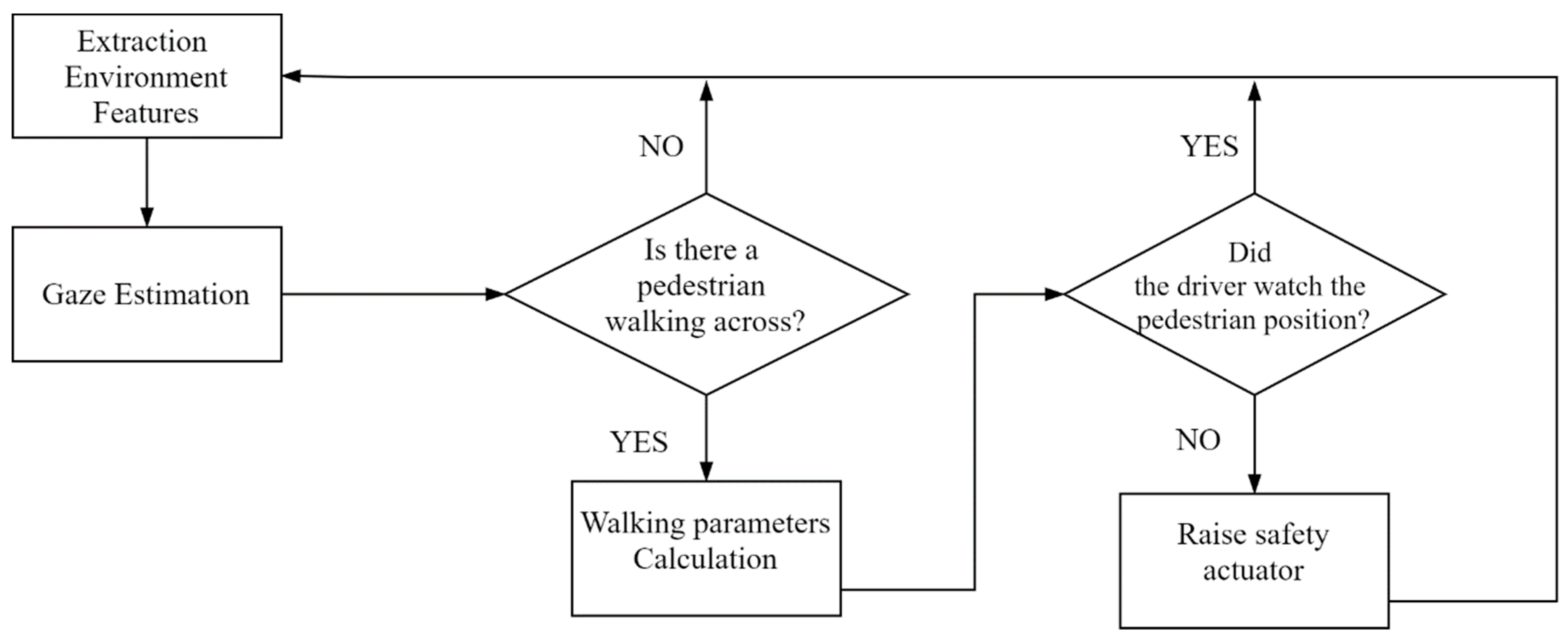
The obtained relative hit ratio of 81.84% among the five possible gaze values defined is also adequate for the system. The warnings of the ADAS should be activated only when it is necessary, i.e., when the driver is not aware of the danger. This way, the driver is not overwhelmed or bored, or both, by the system. Thus, since most of the time, the driver is correctly recognized, we consider that this value is good enough for the objective of the present work. One instance could be the critical case of running over risk in which the driver must be aware of the pedestrian is walking across the road (e.g., Figure 10). For this specific case, the system detects the pedestrian and extracts the main features of their action, such as their walking direction, speed, position respect the ego-vehicle and, the time-to-collision. Afterward, the system evaluates the driver’s gaze to determine the driver’s awareness about this situation (see Figure 11). At this first system approach, the set of rules for this specific case relate the pedestrian position with the driver’s visual zone at each fragment of time from the moment of their detection.
Finally, the best results of the prediction of the system are in the more critical gaze values: Front, Left, and Right. Being able to predict the majority class, Front, makes the system works well most of the time. Also, being able to predict the extreme classes, Left and Right, makes the system detects the driver distractions when the events take place on the other side. Regarding the assessment of the ADAS, drivers exhibit a lower reaction time and most of the critical events, such it was reported by Sipele et al. [59].
7. Conclusions and Future Works
The current number of car accidents comes at both tremendous human and economic cost. It is demonstrated that drivers are less likely (30–43%) to provoke collision-related damage when they have one or more passengers who can alert them. These reasons make it relevant to work in the development of ADAS. The purpose of ADAS is to support the driver in the driving process, improving car safety particularly and road safety generally. Frequently, the driver finds ADAS information overwhelming, and this fact can lead the user to ignore the warnings produced by the system. Developing ADAS that only warns the driver when it is necessary is an essential feature in these kinds of systems.
In this work, we propose a fundamental component of an ADAS that warns the driver only in case of driver distraction, a gaze tracking system. The gaze system obtains and communicates the driver’s gaze information, allowing the ADAS to warn the driver only when it is needed. The developed ADAS uses the gaze information to determine if the driver is paying attention to the road.
The proposed gaze system avoids the problem of intrusive sensors, proposing a frontal camera—a Microsoft Kinect v2.0—for validating the proposal. The gaze tracking system has been validated in a driving simulation environment. It proved to work correctly with a relative hit ratio of 81.84%. The warnings of the ADAS should be activated only when it is necessary, i.e., when the driver is not aware of the danger.
Once the proposal’s viability is complete, the next step will be to test the gaze tracking approach and the ADAS based on the driver in a real car. The proposal is general but may require some adjustments, such as changing the camera sensor or improving the pupil detection system. In addition, due to the results of recent work, we could assess the use of other types of gaze tracking systems.
As limitations of the presented work, the camera location regarding height and distance respect the driving seat is an important aspect to consider in the overall system assessment. Mainly, low illumination impedes obtaining a better rate of pupil location in the image.
There are several future works related to the work done. On the one hand, there are works related to the parameters used in the gaze tracking system that could be adjusted for each driver using an optimization method before starting to use the proposed system. On the other hand, there are works aimed at solving the problem of drivers wearing glasses. Furthermore, the increasing number of gaze areas including divisions along the pitch axis to incorporate the inspection of vehicle dashboard elements such as speedometer and odometer, as well as distinguishing the gaze focused on environment elements. Thirdly, the proposed system could be used with other problems such as controlling the presence and the attention of students in Massive Open Online Courses (MOOCs) or gaze guided User Interfaces (UIs), taking advantage of its main characteristic of being a non-intrusive method.
Finally and given that the main goal of our research works is the construction of an intelligent ADAS that warns only when the driver needs to be warned, a future line of work will be the inclusion of Google’s pupil detection system [62] into the gaze tracking module. In particular, we are interested in analyzing if the inclusion of such system improves the efficiency of the gaze detection module and consequently the efficiency of the ADAS.
Author Contributions
Conceptualization, A.L., V.Z. and A.S.; methodology, M.P.S. and A.L.; software, Ó.S. and V.Z.; validation, V.Z., Ó.S. and M.P.S.; formal analysis, A.S.; investigation, V.Z. and Ó.S.; resources, A.L.; data curation, Ó.S. and V.Z.; writing—original draft preparation, V.Z., Ó.S. and M.P.S.; writing—review and editing, A.S. and A.L.; visualization, A.L. and Ó.S.; supervision, A.L. and A.S.; project administration, A.S.; funding acquisition, A.S. and A.L. All authors have read and agreed to the published version of the manuscript.
Funding
This research received no external funding.
Acknowledgments
We want to acknowledge people for the Universidad Carlos III de Madrid, who have participated in the experiments, for their contributions in the driving tasks. This work has been supported by the Spanish Government under projects TRA2016-78886-C3-1-R, PID2019-104793RB-C31, RTI2018-096036-B-C22, PEAVAUTO-CM-UC3M and by the Region of Madrid’s Excellence Program (EPUC3M17).
Conflicts of Interest
The authors declare no conflict of interest.
References
- World Health Organization. Mobile Phone Use: A Growing Problem of Driver Distraction; World Health Organization: Geneva, Switzerland, 2011. [Google Scholar]
- World Health Organization. Global Status Report on Road Safety; World Health Organization: Geneva, Switzerland, 2015. [Google Scholar]
- Sugiyanto, G.; Santi, M. Road traffic accident cost using human capital method (case study in purbalingga, central java, indonesia). J. Teknol. 2017, 79, 107–116. [Google Scholar] [CrossRef] [Green Version]
- Braitman, K.A.; Chaudhary, N.K.; McCartt, A.T. Effect of Passenger Presence on Older Drivers’ Risk of Fatal Crash Involvement. Traffic Inj. Prev. 2014, 15, 451–456. [Google Scholar] [CrossRef]
- Rueda-Domingo, T.; Lardelli-Claret, P.; Luna-Del-Castillo, J.D.D.; Jimenez-Moleon, J.J.; García-Martín, M.; Bueno-Cavanillas, A. The influence of passengers on the risk of the driver causing a car collision in Spain. Accid. Anal. Prev. 2004, 36, 481–489. [Google Scholar] [CrossRef]
- Bengler, K.; Dietmayer, K.; Farber, B.; Maurer, M.; Stiller, C.; Winner, H. Three Decades of Driver Assistance Systems: Review and Future Perspectives. IEEE Intell. Transp. Syst. Mag. 2014, 6, 6–22. [Google Scholar] [CrossRef]
- TEXA S.p.A. ADAS Solutions. Maintenance of Advanced Driver Assistance Systems (v6). Treviso. 2017. Available online: https://www.texa.ru/PressArea/Brochure/pdf/pieghevole-adas-en-gb-v6.pdf (accessed on 18 June 2021).
- Morales-Fernández, J.M.; Díaz-Piedra, C.; Rieiro, H.; Roca-González, J.; Romero, S.; Catena, A.; Fuentes, L.J.; Di Stasi, L.L. Monitoring driver fatigue using a single-channel electroencephalographic device: A validation study by gaze-based, driving performance, and subjective data. Accid. Anal. Prev. 2017, 109, 62–69. [Google Scholar] [CrossRef] [PubMed]
- Yassine, N.; Barker, S.; Hayatleh, K.; Choubey, B.; Nagulapalli, R. Simulation of driver fatigue monitoring via blink rate detection, using 65 nm CMOS technology. Analog. Integr. Circuits Signal. Process. 2018, 95, 409–414. [Google Scholar] [CrossRef] [Green Version]
- Vahidi, A.; Eskandarian, A. Research advances in intelligent collision avoidance and adaptive cruise control. IEEE Trans. Intell. Transp. Syst. 2003, 4, 143–153. [Google Scholar] [CrossRef] [Green Version]
- Lee, J.; Hoffman, J.D.; Hayes, E. Collision warning design to mitigate driver distraction. In Proceedings of the 2004 Conference on Applications, Technologies, Architectures, and Protocols for Computer Communications—SIGCOMM ’04; Association for Computing Machinery: New York, NY, USA, 2004; pp. 65–72. [Google Scholar]
- Gutierrez, G.; Iglesias, J.A.; Ordoñez, F.J.; Ledezma, A.; Sanchis, A. Agent-based framework for Advanced Driver Assistance Systems in urban environments. In Proceedings of the 17th International Conference on Information Fusion, Salamanca, Spain, 7–10 July 2014; pp. 1–8. [Google Scholar]
- Sipele, O.; Zamora, V.; Ledezma, A.; Sanchis, A. Testing ADAS though simulated driving situations analysis: Environment configuration. In Proceedings of the First Symposium SEGVAUTO-TRIES-CM. Technologies for a Safe, Accessible and Sustainable Mobility; R&D+I in Automotive: RESULTS: Madrid, Spain, 2016; pp. 23–26. [Google Scholar]
- Zamora, V.; Sipele, O.; Ledezma, A.; Sanchis, A. Intelligent Agents for Supporting Driving Tasks: An Ontology-based Alarms System. In Proceedings of the 3rd International Conference on Vehicle Technology and Intelligent Transport Systems; Science and Technology Publications: Setúbal, Portugal, 2017; pp. 165–172. [Google Scholar]
- Dickmanns, E.D.; Mysliwetz, B.D. Recursive 3-D road and relative ego-state recognition. IEEE Trans. Pattern Anal. Mach. Intell. 1992, 14, 199–213. [Google Scholar] [CrossRef]
- Viktorová, L.; Šucha, M. Learning about advanced driver assistance systems—The case of ACC and FCW in a sample of Czech drivers. Transp. Res. Part. F Traffic Psychol. Behav. 2019, 65, 576–583. [Google Scholar] [CrossRef]
- Singh, S. Critical Reasons for Crashes Investigated in the National Motor Vehicle Crash Causation Survey. 2015. Available online: http://www-nrd.nhtsa.dot.gov/Pubs/812115.pdf (accessed on 30 April 2021).
- Khan, M.Q.; Lee, S. Gaze and Eye Tracking: Techniques and Applications in ADAS. Sensors 2019, 19, 5540. [Google Scholar] [CrossRef] [Green Version]
- Dong, Y.; Hu, Z.; Uchimura, K.; Murayama, N. Driver Inattention Monitoring System for Intelligent Vehicles: A Review. IEEE Trans. Intell. Transp. Syst. 2011, 12, 596–614. [Google Scholar] [CrossRef]
- Sigari, M.-H.; Pourshahabi, M.-R.; Soryani, M.; Fathy, M. A Review on Driver Face Monitoring Systems for Fatigue and Distraction Detection. Int. J. Adv. Sci. Technol. 2014, 64, 73–100. [Google Scholar] [CrossRef]
- Morimoto, C.H.; Mimica, M.R. Eye gaze tracking techniques for interactive applications. Comput. Vis. Image Underst. 2005, 98, 4–24. [Google Scholar] [CrossRef]
- Jiang, J.; Zhou, X.; Chan, S.; Chen, S. Appearance-Based Gaze Tracking: A Brief Review. In Transactions on Petri Nets and Other Models of Concurrency XV; Springer: Berlin/Heidelberg, Germany, 2019; Volume 11745, pp. 629–640. [Google Scholar]
- Wang, Y.; Yuan, G.; Mi, Z.; Peng, J.; Ding, X.; Liang, Z.; Fu, X. Continuous Driver’s Gaze Zone Estimation Using RGB-D Camera. Sensors 2019, 19, 1287. [Google Scholar] [CrossRef] [Green Version]
- Wang, Y.; Zhao, T.; Ding, X.; Peng, J.; Bian, J.; Fu, X. Learning a gaze estimator with neighbor selection from large-scale synthetic eye images. Knowl.-Based Syst. 2018, 139, 41–49. [Google Scholar] [CrossRef]
- Zhang, Y.; Bulling, A.; Gellersen, H. Discrimination of gaze directions using low-level eye image features. In Proceedings of the 1st International Workshop on Real World Domain Specific Languages; Association for Computing Machinery: New York, NY, USA, 2011; pp. 9–14. [Google Scholar]
- Wang, Y.; Shen, T.; Yuan, G.; Bian, J.; Fu, X. Appearance-based gaze estimation using deep features and random forest regression. Knowl.-Based Syst. 2016, 110, 293–301. [Google Scholar] [CrossRef]
- Huang, Q.; Veeraraghavan, A.; Sabharwal, A. TabletGaze: Dataset and analysis for unconstrained appearance-based gaze estimation in mobile tablets. Mach. Vis. Appl. 2017, 28, 445–461. [Google Scholar] [CrossRef]
- Wu, Y.-L.; Yeh, C.-T.; Hung, W.-C.; Tang, C.-Y. Gaze direction estimation using support vector machine with active appearance model. Multimedia Tools Appl. 2014, 70, 2037–2062. [Google Scholar] [CrossRef]
- Baluja, S.; Pomerleau, D. Non-Intrusive Gaze Tracking Using Artificial Neural Networks. In Proceedings of the Advances in Neural Information Processing Systems 6, 7th {NIPS} Conference, Denver, Colorado, USA, 1993; Cowan, J.D., Tesauro, G., Alspector, J., Eds.; Morgan Kaufmann, 1993; pp. 753–760. Available online: https://www.aaai.org/Papers/Symposia/Fall/1993/FS-93-04/FS93-04-032.pdf. (accessed on 26 April 2021).
- Vora, S.; Rangesh, A.; Trivedi, M.M. On generalizing driver gaze zone estimation using convolutional neural networks. In Proceedings of the 2017 IEEE Intelligent Vehicles Symposium (IV), Los Angeles, CA, USA, 11–14 June 2017; pp. 849–854. [Google Scholar]
- Palmero, C.; Selva, J.; Bagheri, M.A.; Escalera, S. Recurrent CNN for 3D Gaze Estimation using Appearance and Shape Cues. arXiv 2018. Available online: http://arxiv.org/abs/1805.03064 (accessed on 24 May 2021).
- Gu, S.; Wang, L.; He, L.; He, X.; Wang, J. Gaze Estimation via a Differential Eyes’ Appearances Network with a Reference Grid. Engineering 2021. [Google Scholar] [CrossRef]
- Cazzato, D.; Leo, M.; Distante, C.; Voos, H. When I Look into Your Eyes: A Survey on Computer Vision Contributions for Human Gaze Estimation and Tracking. Sensors 2020, 20, 3739. [Google Scholar] [CrossRef] [PubMed]
- Sesma, L.S. Gaze Estimation: A Mathematical Challenge; Public University of Navarre: Navarre, Spain, 2017. [Google Scholar]
- Chen, J.; Tong, Y.; Gray, W.; Ji, Q. A robust 3D eye gaze tracking system using noise reduction. In Proceedings of the 2008 Symposium on Eye Tracking Research & Applications—ETRA ’08; ACM: New York, NY, USA, 2008; pp. 189–196. [Google Scholar]
- Guestrin, E.D.; Eizenman, M. General Theory of Remote Gaze Estimation Using the Pupil Center and Corneal Reflections. IEEE Trans. Biomed. Eng. 2006, 53, 1124–1133. [Google Scholar] [CrossRef] [PubMed]
- Lee, E.C.; Park, K.R. A robust eye gaze tracking method based on a virtual eyeball model. Mach. Vis. Appl. 2009, 20, 319–337. [Google Scholar] [CrossRef]
- Wang, K.; Su, H.; Ji, Q. Neuro-Inspired Eye Tracking With Eye Movement Dynamics. In Proceedings of the 2019 IEEE/CVF Conference on Computer Vision and Pattern Recognition (CVPR), Long Beach, CA, USA, 15–20 June 2019; Volume 2019, pp. 9823–9832. [Google Scholar]
- Brousseau, B.; Rose, J.; Eizenman, M. Accurate Model-Based Point of Gaze Estimation on Mobile Devices. Vision 2018, 2, 35. [Google Scholar] [CrossRef] [Green Version]
- iMotions ASL Eye Tracking Glasses. 2018. Available online: https://imotions.com/hardware/argus-science-eye-tracking-glasses/ (accessed on 1 May 2021).
- Improving Your Research with Eye Tracking Since 2001|Tobii Pro. Available online: https://www.tobiipro.com/ (accessed on 1 May 2021).
- Wang, K.; Ji, Q. Real time eye gaze tracking with Kinect. In Proceedings of the 2016 23rd International Conference on Pattern Recognition (ICPR), Cancun, Mexico, 4–8 December 2016; pp. 2752–2757. [Google Scholar]
- Zhou, X.; Cai, H.; Li, Y.; Liu, H. Two-eye model-based gaze estimation from a Kinect sensor. In Proceedings of the 2017 IEEE International Conference on Robotics and Automation (ICRA), Singapore, 29 May–3 June 2017; pp. 1646–1653. [Google Scholar]
- Al-Naser, M.; Siddiqui, S.A.; Ohashi, H.; Ahmed, S.; Katsuyki, N.; Takuto, S.; Dengel, A. OGaze: Gaze Prediction in Egocentric Videos for Attentional Object Selection. In Proceedings of the 2019 Digital Image Computing: Techniques and Applications (DICTA), Perth, WA, Australia, 2–4 December 2019; pp. 1–8. [Google Scholar] [CrossRef]
- Fathi, A.; Li, Y.; Rehg, J. Learning to Recognize Daily Actions Using Gaze. In Proceedings of the 12th European Conference on Computer Vision, Florence, Italy, 7–13 October 2012. [Google Scholar]
- Zhang, M.; Ma, K.T.; Lim, J.H.; Zhao, Q.; Feng, J. Deep Future Gaze: Gaze Anticipation on Egocentric Videos Using Adversarial Networks. In Proceedings of the 2017 IEEE Conference on Computer Vision and Pattern Recognition (CVPR), Honolulu, HI, USA, 21–26 July 2017; Volume 2017, pp. 3539–3548. [Google Scholar]
- Liu, G.; Yu, Y.; Mora, K.A.F.; Odobez, J.-M. A Differential Approach for Gaze Estimation. IEEE Trans. Pattern Anal. Mach. Intell. 2021, 43, 1092–1099. [Google Scholar] [CrossRef] [PubMed] [Green Version]
- Deng, H.; Zhu, W. Monocular Free-Head 3D Gaze Tracking with Deep Learning and Geometry Constraints. In Proceedings of the 2017 IEEE International Conference on Computer Vision (ICCV), Venice, Italy, 22–29 October 2017; Volume 2017, pp. 3162–3171. [Google Scholar]
- Hagl, M.; Kouabenan, D.R. Safe on the road—Does Advanced Driver-Assistance Systems Use affect Road Risk Perception? Transp. Res. Part. F Traffic Psychol. Behav. 2020, 73, 488–498. [Google Scholar] [CrossRef]
- Biondi, F.; Strayer, D.L.; Rossi, R.; Gastaldi, M.; Mulatti, C. Advanced driver assistance systems: Using multimodal redundant warnings to enhance road safety. Appl. Ergon. 2017, 58, 238–244. [Google Scholar] [CrossRef]
- Narote, S.P.; Bhujbal, P.N.; Narote, A.S.; Dhane, D. A review of recent advances in lane detection and departure warning system. Pattern Recognit. 2018, 73, 216–234. [Google Scholar] [CrossRef]
- Voinea, G.-D.; Postelnicu, C.C.; Duguleana, M.; Mogan, G.-L.; Socianu, R. Driving Performance and Technology Acceptance Evaluation in Real Traffic of a Smartphone-Based Driver Assistance System. Int. J. Environ. Res. Public Health 2020, 17, 7098. [Google Scholar] [CrossRef]
- Systems Technology Incorporated STISIM Drive: Car Driving Simulator. Available online: https://stisimdrive.com/ (accessed on 1 May 2021).
- Haugen, I.-B.K. Structural Organisation of Proprioceptors in the Oculomotor System of Mammals. 2002. Available online: https://openarchive.usn.no/usn-xmlui/bitstream/handle/11250/142006/3702haugen.pdf?sequence=1 (accessed on 21 April 2021).
- Toquero, S.O.; Cristóbal, A.d.S.; Herranz, R.M.; Herráez, V.d.; Zarzuelo, G.R. Relación de los parámetros biométricos en el ojo miope. Gac. Optom. Óptica Oftálmica 2012, 474, 16–22. [Google Scholar]
- García, J.P. Estrabismos. Artes Gráficas Toledo. 2008. Available online: http://www.doctorjoseperea.com/libros/estrabismos.html (accessed on 21 April 2021).
- Emgu CV: OpenCV in .NET (C#, VB, C++ and More). Available online: https://www.emgu.com/wiki/index.php/Main_Page (accessed on 4 May 2021).
- Ulbrich, S.; Menzel, T.; Reschka, A.; Schuldt, F.; Maurer, M. Defining and Substantiating the Terms Scene, Situation, and Scenario for Automated Driving. In Proceedings of the 2015 IEEE 18th International Conference on Intelligent Transportation Systems, Gran Canaria, Spain, 15–18 September 2015; pp. 982–988. [Google Scholar]
- Sipele, O.; Zamora, V.; Ledezma, A.; Sanchis, A. Advanced Driver’s Alarms System through Multi-agent Paradigm. In Proceedings of the 2018 3rd IEEE International Conference on Intelligent Transportation Engineering (ICITE), Singapore, 3–5 September 2018; pp. 269–275. [Google Scholar]
- ViPER-GT. Available online: http://viper-toolkit.sourceforge.net/products/gt/ (accessed on 4 May 2021).
- Ethical Aspects|UC3M. Available online: https://www.uc3m.es/ss/Satellite/LogoHRS4R/en/TextoMixta/1371234170165/Ethical_Aspects (accessed on 1 May 2021).
- Lugaresi, C.; Tang, J.; Nash, H.; McClanahan, C.; Uboweja, E.; Hays, M.; Zhang, F.; Chang, C.L.; Yong, M.G.; Lee, J.; et al. MediaPipe: A Framework for Building Perception Pipelines. arXiv 2019, arXiv:1906.08172. [Google Scholar]
Figure 1.
Alarms are not shown when the driver is attentive. However, when the situation becomes critical (e.g., the distance is very short, and there is no reaction of the driver) the alarm is launched preventively.
Figure 1.
Alarms are not shown when the driver is attentive. However, when the situation becomes critical (e.g., the distance is very short, and there is no reaction of the driver) the alarm is launched preventively.

Figure 2.
The 3D eye model, based on [42].
Figure 2.
The 3D eye model, based on [42].

Figure 3.
Flow diagram for gaze area estimation from an input image.
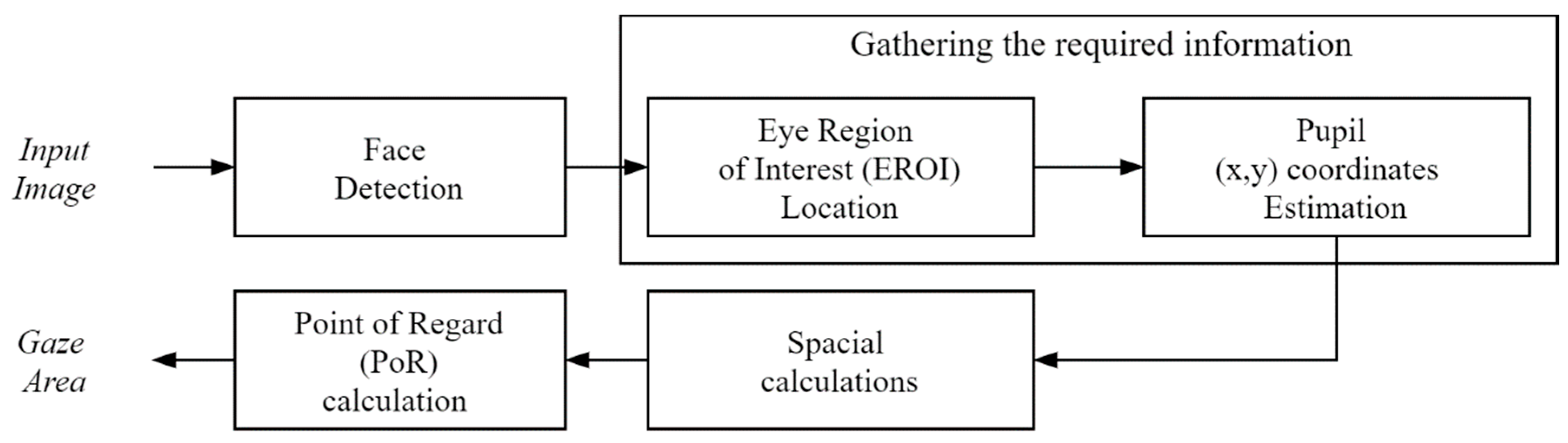
Figure 4.
Segmentation process for locating the x and y coordinates of the pupil.
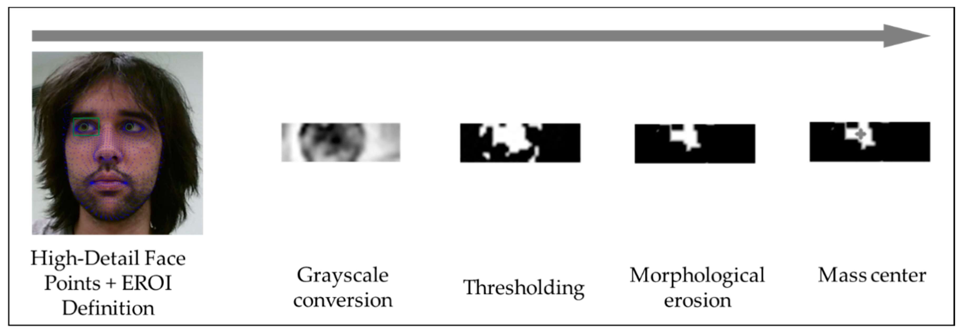
Figure 5.
Point of Regard (PoR) extracted from the intersection between the gaze direction and screen plane. Pupil detection (green circle, A), gaze direction line (white circles, B), PoR (cyan circle, C) and the center of the image (red circle, D).
Figure 5.
Point of Regard (PoR) extracted from the intersection between the gaze direction and screen plane. Pupil detection (green circle, A), gaze direction line (white circles, B), PoR (cyan circle, C) and the center of the image (red circle, D).
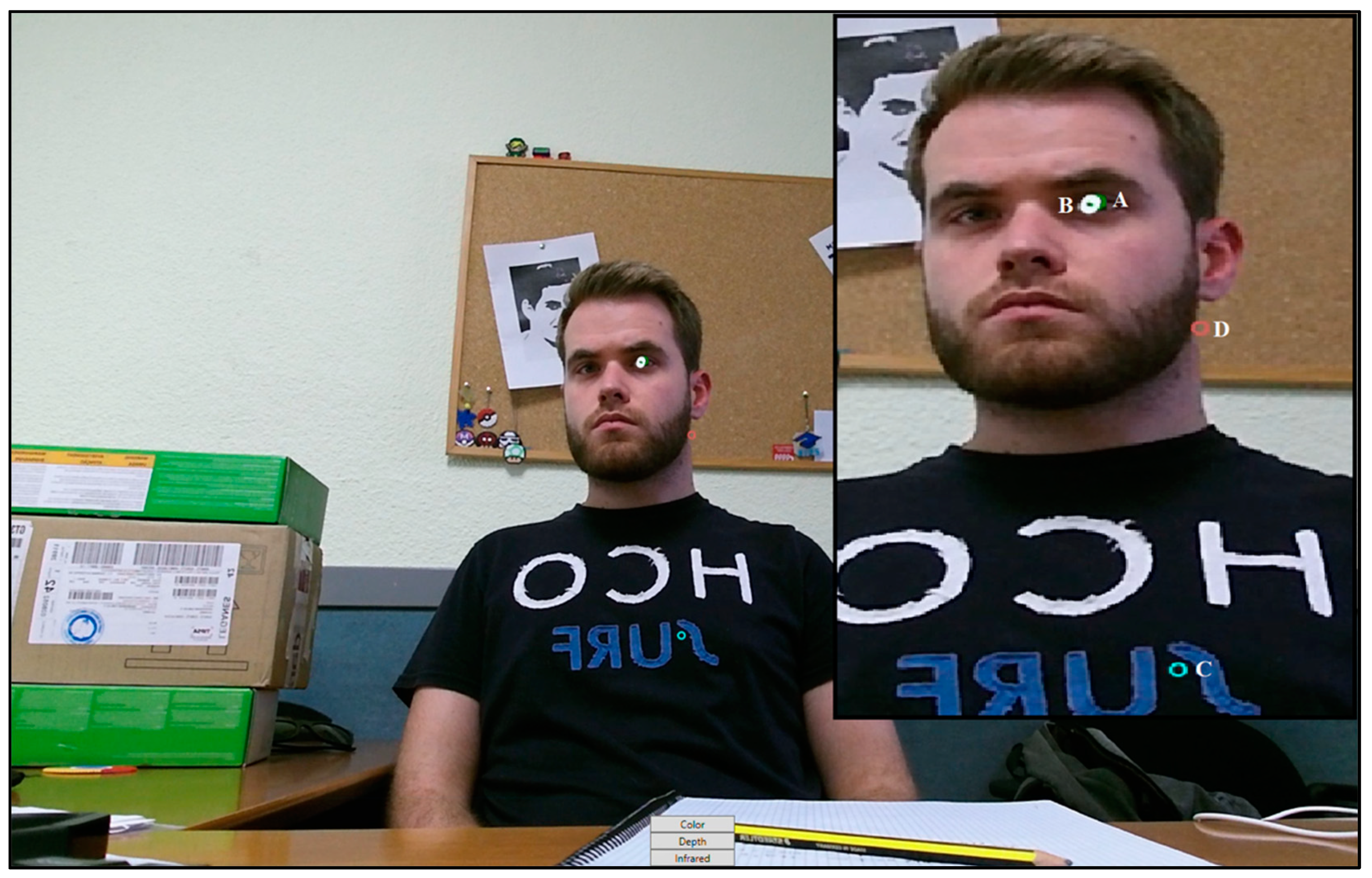
Figure 6.
Gaze values from the driver’s perspective.

Figure 7.
UML component diagram of deployed ADAS based on data-fusion.
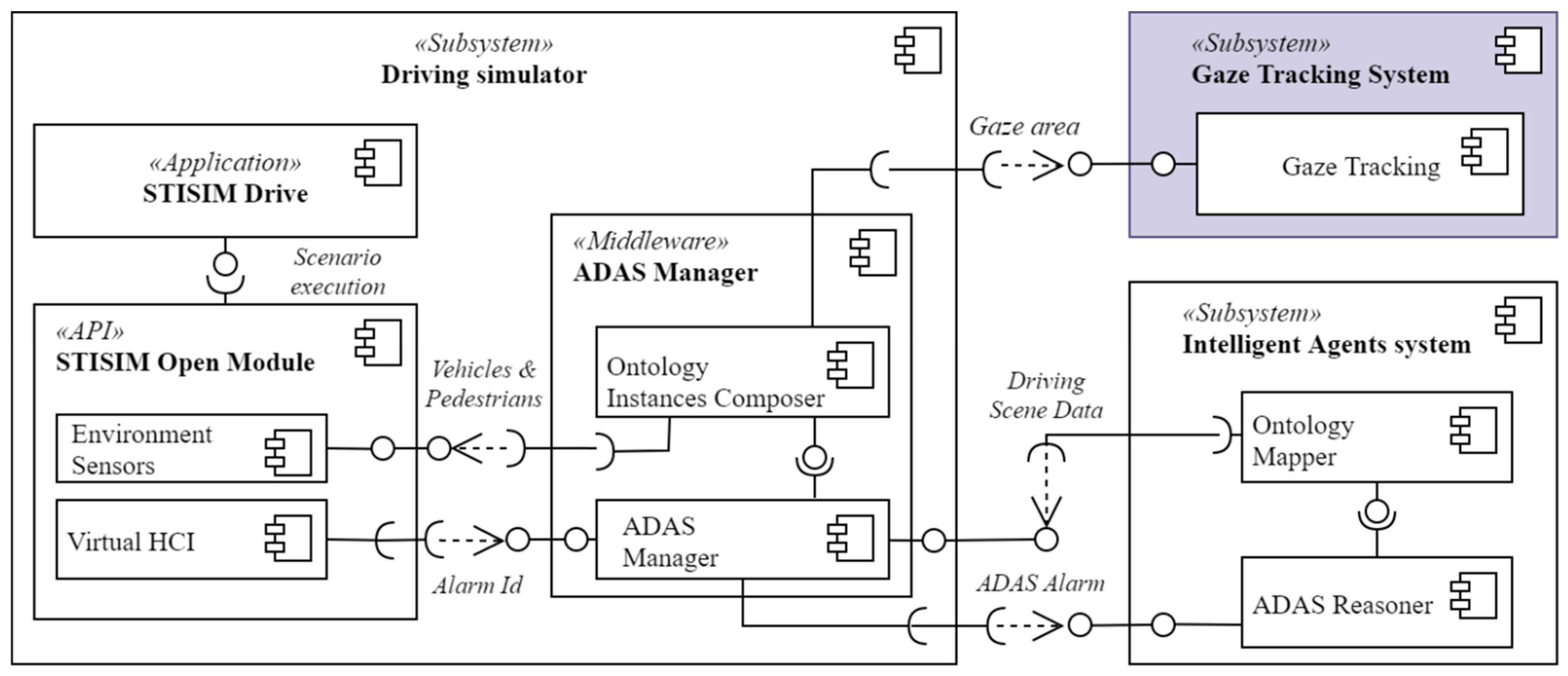
Figure 8.
The presentation of a running over scene in a simulation scenario (a) Driver comes into the scene (b) the hazard situation is exposed to the driver (c) the driver can perceive visually the situation (d) the driver reacts by braking the car to face the scene.
Figure 8.
The presentation of a running over scene in a simulation scenario (a) Driver comes into the scene (b) the hazard situation is exposed to the driver (c) the driver can perceive visually the situation (d) the driver reacts by braking the car to face the scene.

Figure 9.
Ground-truth process of the gaze area using ViperGT tool.
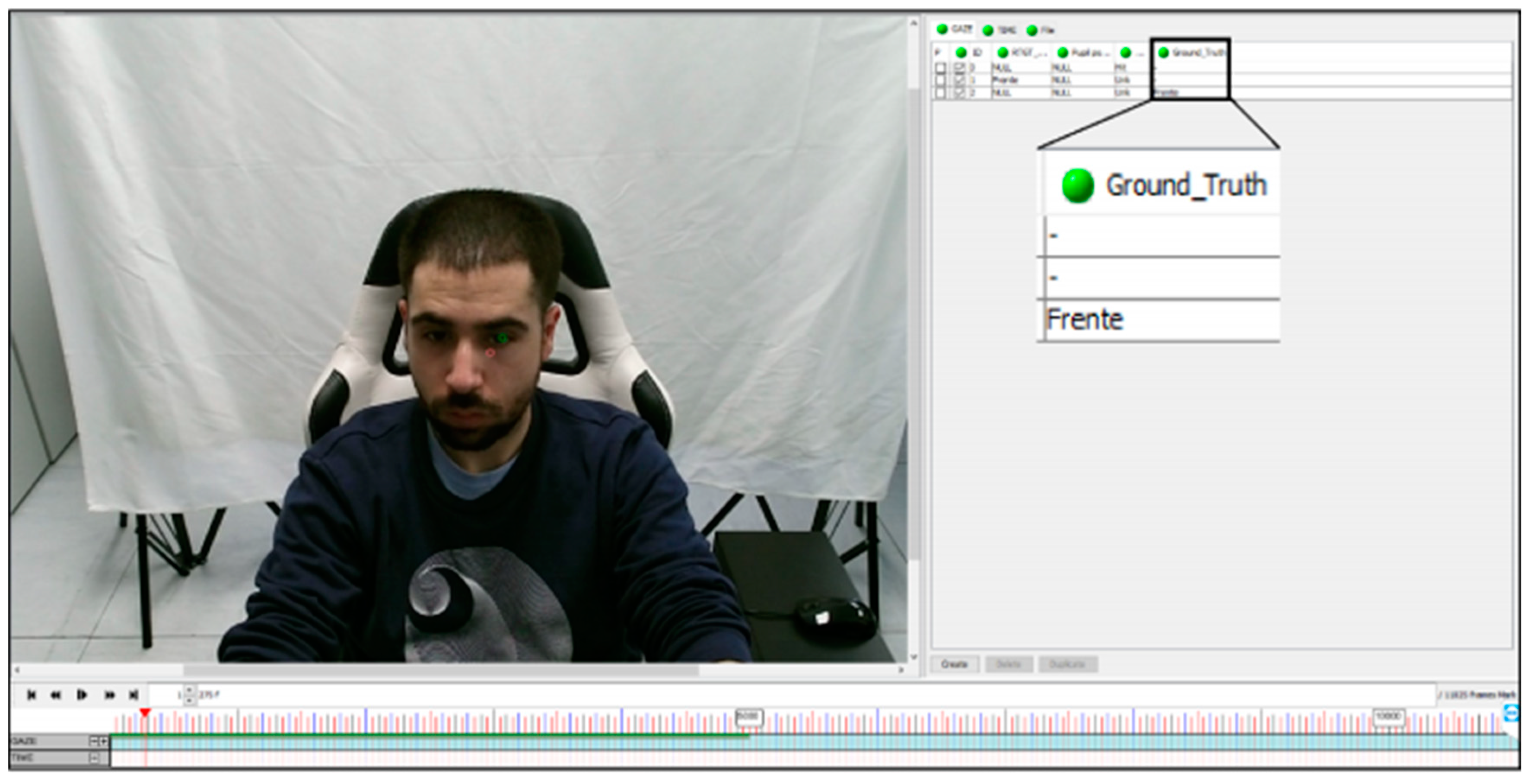
Figure 10.
Example of ADAS raising a pedestrian crossing warning.

Figure 11.
Flow diagram of rule-based system for running over risk.

Table 1.
Theoretical comparison of gaze tracking methods (based on [33]).
Table 1.
Theoretical comparison of gaze tracking methods (based on [33]).
| Method/Year | Sensor | Frame Rate | Limitations | Domain | Accuracy | Advantages | Disadvantages |
|---|---|---|---|---|---|---|---|
| Our approach | RGBD | 30 fps at 1920 × 1080 | Camera location | Simulated driving environment | 81.84% over inspectioned areas | Calibration process is not required | Pupil location detection is improvable |
| 3D data available | |||||||
| data | |||||||
| [42] 2016 | RGBD | 30 fps at 640 × 480 | Person calibration | Screen display | 4.0 degrees | 3D data available | Low resolution affects the operation distance (800 mm) |
| [43] 2017 | RGBD | - | Person calibration | Points on a monitor | 1.99 degrees | 3D data available data | Not reproducible |
| Camera limitations (e.g., distance) | |||||||
| [44] 2019 | Glasses | 13–18 fps | Person calibration | Industrial Scenario | 7.39 Average Angular Error | Consider gaze as a classification and regression problem | Not reproducible |
| High precision | Intrusive | ||||||
| [47] 2019 | RGB | 666 fps | Person calibration | Public datasets | 3~5.82 Average Angular Error | Robust to eyelid closing or illumination perturbations | High run-time |
| Not reproducible | |||||||
| 3D data not available | |||||||
| [48] 2017 | RGB | 1000 fps | - | Public datasets, screen display | - | More usability | Face alignment time to be considered |
| Less precision | |||||||
| 3D only estimable |
Table 2.
Confusion matrix and results of the set-up environment adjustment experiment.
| True Zone | Recognized Gaze Zone | ||||
|---|---|---|---|---|---|
| Left | 100 | 0 | 0 | 0 | 0 |
| Front-Left | 6.91 | 93.09 | 0 | 0 | 0 |
| Front | 0 | 3.08 | 96.57 | 0.35 | 0 |
| Front-Right | 0 | 0 | 4.37 | 93.40 | 2.23 |
| Right | 0 | 0 | 0 | 0.44 | 99.56 |
| Unknown ratio: 0.79% | |||||
| Hit ratio (absolute): 95.60% | |||||
| Hit ratio (relative): 96.37% | |||||
| Mean error: 3.63% | |||||
Table 3.
Confusion matrix and results of the driving simulator environment experiment.
| True Zone | Recognized Gaze Zone | ||||
|---|---|---|---|---|---|
| Left | 68.77 | 21.33 | 9.90 | 0 | 0 |
| Front-Left | 2.57 | 51.51 | 44.09 | 1.39 | 0.44 |
| Front | 0 | 2.08 | 93.05 | 4.65 | 0.22 |
| Front-Right | 0 | 2.35 | 31.93 | 64.78 | 0.94 |
| Right | 0 | 0 | 20.61 | 13.74 | 65.65 |
| Unknown ratio: 11.16% | |||||
| Hit ratio (absolute): 72.69% | |||||
| Hit ratio (relative): 81.84% | |||||
| Mean error: 19.14% | |||||
Publisher’s Note: MDPI stays neutral with regard to jurisdictional claims in published maps and institutional affiliations. |
© 2021 by the authors. Licensee MDPI, Basel, Switzerland. This article is an open access article distributed under the terms and conditions of the Creative Commons Attribution (CC BY) license (https://creativecommons.org/licenses/by/4.0/).
Share and Cite
MDPI and ACS Style
Ledezma, A.; Zamora, V.; Sipele, Ó.; Sesmero, M.P.; Sanchis, A. Implementing a Gaze Tracking Algorithm for Improving Advanced Driver Assistance Systems. Electronics 2021, 10, 1480. https://doi.org/10.3390/electronics10121480
AMA Style
Ledezma A, Zamora V, Sipele Ó, Sesmero MP, Sanchis A. Implementing a Gaze Tracking Algorithm for Improving Advanced Driver Assistance Systems. Electronics. 2021; 10(12):1480. https://doi.org/10.3390/electronics10121480
Chicago/Turabian StyleLedezma, Agapito, Víctor Zamora, Óscar Sipele, M. Paz Sesmero, and Araceli Sanchis. 2021. "Implementing a Gaze Tracking Algorithm for Improving Advanced Driver Assistance Systems" Electronics 10, no. 12: 1480. https://doi.org/10.3390/electronics10121480
Note that from the first issue of 2016, this journal uses article numbers instead of page numbers. See further details here.