
Rollover Index for Rollover Mitigation Function of Intelligent Commercial Vehicle’s Electronic Stability Control


1
Department of Mechanical Systems Engineering, Sookmyung Women’s University, Seoul 04310, Korea
2
R&D Division, Hyundai Motor Company, Hwaseoung-si 18280, Korea
3
Department of Electrical Engineering, College of Convergence Technology, Korea National University of Transportation, Chungju-si 27469, Korea
*
Authors to whom correspondence should be addressed.
Electronics 2021, 10(21), 2605; https://doi.org/10.3390/electronics10212605
Submission received: 18 September 2021
/
Revised: 21 October 2021
/
Accepted: 22 October 2021
/
Published: 25 October 2021
(This article belongs to the Special Issue Intelligent Systems and Control Application in Autonomous Vehicle)
Abstract
:This paper describes a rollover index for detection or prediction of impending rollover in different driving situations using minimum sensor signals which can be easily obtained from an electronic stability control (ESC) system. The estimated lateral load transfer ratio (LTR) was used as a rollover index with only limited information such as the roll state of the vehicle and some constant parameters. A commercial vehicle has parameter uncertainties because of its load variation. This is likely to affect the driving performance and the estimation of the dynamic state of the vehicle. The main purpose of this paper is to determine the rollover index based on reliable measurements and the parameters of the vehicle. For this purpose, a simplified lateral and vertical vehicle dynamic model was used with some assumptions. The index is appropriate for various situations although the vehicle parameters may change. As part of the index, the road bank angle was investigated in this study, using limited information. Since the vehicle roll dynamics are affected by the road bank angle, the road bank angle should be incorporated, although previous studies ignore this factor in order to simplify the problem. Because it increases or reduces the chances of rollover, consideration of the road bank angle is indispensable in the rollover detection and mitigation function of the ESC system. The performance of the proposed algorithm was investigated via computer simulation studies. The simulation studies showed that the proposed estimation method of the LTR and road bank angle with limited sensor information followed the actual LTR value, reducing the parameter uncertainties. The simulation model was constructed based on a heavy bus (12 tons).
1. Introduction
Rollover is a major cause of road accidents that result in fatal injuries to passengers. Statistics show that 28.3% of highway fatalities in the US are related to rollover; nevertheless, only a very small proportion of traffic crashes involve rollover [1]. Rollover prevention studies play a vital role in the safety of commercial vehicles, especially [2,3,4]. Commercial vehicles such as single-unit trucks, large buses or large tractor-trailers have their own characteristics. Firstly, the size of a commercial vehicle is much greater than that of conventional vehicles. Due to the load of a commercial vehicle, the center of gravity or roll center is much higher than that of general vehicles, increasing the likelihood of rollover. Electronic stability control (ESC) is widely used for the mitigation of rollover in commercial vehicles. To mitigate rollover, the detection and prediction of impending rollover is required.
Rollover detection or prediction is the subject of many studies [5,6,7,8]. Most of them propose methods related to a rollover index, which is a dimensionless number that indicates an impending rollover to capture the rollover probability. These rollover indexes usually use the roll state or vehicle dynamic properties to investigate the rollover probability. Since the characteristic parameters of commercial vehicles vary considerably compared to normal vehicles, the rollover index is less likely to be accurate. The longitudinal mass distribution changes depending on the position of the additional load. This affects the tire stiffness of front and rear tires by producing a huge change in the vehicle lateral dynamics. Likewise, the parameter uncertainty of commercial vehicles leads to variation in the characteristics of the vehicle.
It is well known that a lateral load transfer ratio (LTR) is often used for rollover indexes, to detect impending rollover. In order to achieve a more accurate LTR, the multiple effects of uncertainties due to the height of the vehicle’s center of gravity, road disturbances, and sensor failures must be considered, based on a nonlinear two-wheel vehicular system [9]. Li et al. [10] introduced an improved predictive LTR (IPLTR) which was based on an 8-DOF nonlinear vehicle model. Yoon et al. [11] suggest a rollover-index-based (RI-based) vehicle stability control (VSC) scheme. The rollover index is computed using the estimated roll angle, estimated roll rate, measured lateral acceleration, and time to wheel lift. This requires a huge amount of computational resource for a real-time estimation [11]. In [12], a real-time sampling and process system is presented. Although the estimator with an extended Kalman filter (EKF) and a particle filter was developed as a real-time application, it is widely known that the estimator that computes EKF and PF cannot be easily adopted at the level of mass production vehicles due to the fact that it is implemented on a comparatively high-performance PC. In [13], the test vehicle was equipped with an accelerometer, a gyro, a GPS, a steering angle sensor, and suspension stroke sensors to detect roll and yaw motion. This requires more than three sensors, which increases the complexity of development. In order to achieve a better driving performance including rollover prevention, four-wheel independent drive/steering electric vehicles (4WID-4WIS EV) have been introduced and discussed [14]. The X-by-wire chassis technique is a critical issue for the successful development of autonomous commercial vehicles in the future, since it does not restrict the autonomous driving platform design. Future commercial vehicle design can be realized through integrated X-by-wire modules of 4WID-4WIS EV by considering rollover prevention control while ensuring sufficient space inside the vehicle [14].
The main contribution of this study is to develop a rollover index that can be directly implemented in the existing controller in order to reduce the cost and complexity of the mass production development process. In this paper, a simplified rollover index using only the measured lateral acceleration information is presented. This index aims to detect the impending rollover using only the limited information which can be easily obtained from the factory-installed ESC system. This paper also proposes a bank angle estimation method, also using the limited information provided by the ESC system. The road bank angle is ignored in many studies, although it directly affects the roll state of the vehicle by increasing or reducing the chances of rollover, and therefore it is important to include the road bank angle estimation function in the standard ESC systems of commercial vehicles. This also affects the parameter variations of the vehicle, which change with time or other conditions. It is necessary to ensure that it is not affected by the parameter uncertainties. The rest of the paper describes the simulation studies on the proposed estimation method of LTR and road bank angle with limited sensor information, showing that the estimation follows the actual LTR value, reducing the parameter uncertainties.
2. Rollover Index
In this paper, the lateral load transfer ratio(LTR) is used as a rollover index. The rollover index is a dimensionless number that indicates an impending rollover.
2.1. Lateral Load Transfer Ratio
The LTR is a common index that is used to quantify vehicle rollover propensity. It is defined as
where and are the vertical forces on the left and right tires. The LTR varies from −1 to 1. An LTR value of 1 or −1 means that the right or left tire, respectively, loses contact with the ground [9]. This tire lift means that vehicle rollover is impending. An LTR value of 0 means that the load is distributed equally on both sides. This means that there is no roll angle. This index is widely used for the prediction of vehicle rollover.
However, the vertical tire force is hard to measure, because vertical force sensors are expensive and normal mass production vehicles are not usually equipped with them. Hence, there is a great deal of research aimed at estimating the LTR value.
In this paper, the LTR value is estimated using the measured lateral acceleration value.
2.2. Vehicle Model
The dynamic model of the vehicle is shown in Figure 1 and Figure 2. The equations of motion can be written as
where
Let us assume that the bank angle is zero. Then the equations of motion can be written as
2.3. Lateral-Acceleration-Based LTR
With a steady state assumption (), we can obtain the LTR by calculating and using (2). The LTR can be estimated as
Using assumptions
the LTR can be obtained as
Here, is smaller than and is approximately proportional to the lateral acceleration.
where is a constant which changes depending on the center of gravity point and the suspension parameters.
Using this information, we can determine the estimated LTR as
3. Bank Angle Estimator
In many studies, the bank angle is assumed to be zero, to simplify the problem. However, the bank angle can result in vehicle rollover with a small maneuver. Therefore, it is important to consider the bank angle.
The vehicle vertical model is shown in Figure 3. In this model, contains a gravitational component. Hence, we can obtain the road bank angle using measured lateral acceleration information.
In vehicle lateral dynamics, the measured yaw rate and measured lateral acceleration can be expressed as
From these equations, the bank angle can be obtained as
Let us assume that (steady state assumption), then
4. Simulation Studies
To evaluate the proposed estimation method for LTR and the road bank angle, computer simulations using the vehicle simulation program CarSim and MATLAB/Simulink were implemented. The vehicle model was based on a heavy commercial vehicle (12-ton bus), which is currently in the virtual development stage within this model. The estimated LTR, which is widely known as a rollover index, was compared with the actual LTR obtained from the simulation results. The road bank angle was also compared with the actual road bank angle from the simulation studies.
4.1. Simulation Environment
To evaluate the performance of the estimator of LTR, four scenarios were investigated. A slowly increasing steering maneuver, and a 60 deg step steer, were used as typical steady maneuvers. A 120 deg step steer and a sine with dwell maneuver were used as typical unsteady maneuvers. The vehicle was assumed to be loaded with a normal load (1500 kg), the road was assumed to be dry asphalt with a friction coefficient of 0.85, and every test was an open loop steering control maneuver.
By simulating these four test scenarios, the performance of the rollover index was evaluated. To evaluate the performance of the estimator of the road bank angle, four other scenarios were used. A straight road with a bank angle at both sides was used at vehicle speeds of 50 kph and 70 kph. In addition, an S-curve with a bank angle on the inside of the curve was implemented at vehicle speeds of 50 kph and 70 kph. By simulating these four test scenarios, the performance of the rollover index was evaluated. The effects of bank angle and yaw rate when turning through the curve were separated.
4.2. Simulation Results
In the simulations, is a constant related to the center of gravity point and suspension parameters. The simulation result is shown in Figure 4. When the constant is 0.012, and are almost the same.
Using this information, we can determine the estimated LTR as
LTR and the actual LTR are shown in Figure 5. This shows that the estimated LTR value is almost same as the actual LTR value.
However, the measured lateral acceleration information already contains the gravitational component. The estimated LTR and actual LTR values are shown in Figure 6. This shows that the estimated LTR shows good performance even in the situation where the road has a bank angle.
The simulation results for the estimated bank angle are shown in Figure 7. The figures show that this estimation is valid only for small vehicle roll angles. When the vehicle speed is large in the curve, the vehicle roll angle affects the estimated bank angle.
4.3. Calibration to Develop a Mass Production Vehicle
Although the proposed index is already simplified to reduce the cost and complexity of mass production development, there are some parameters in the estimator. It is crucial to calibrate the parameters during the development stage. The parameter of the track width of the vehicle does not change with the vehicle condition for the rigid axle suspension of commercial vehicles. This can be set using the design value of the vehicle. The parameter of the roll center height experiences a relatively small change with loading condition in the rigid axle suspension of commercial vehicles, due to their much stiffer springs compared to normal vehicles. This also can be set to the design value for the unloaded state.
The parameter of the center of gravity (CG) height is the only uncertain parameter due to the loading condition. As the CG height increases for large loads, the LTR is calculated as a larger value. Therefore, this should be set to the largest value corresponding to the maximum loading condition, in order to prepare for the worst case. In this case, although the LTR is calculated too conservatively for the empty vehicle state, this is appropriate because safety should be considered as the first priority for a commercial vehicle, rather than driving fun. Another advantage is that the rollover mitigation control starts at a similar level of lateral acceleration regardless of the loading condition. In other words, since the level of lateral acceleration that alerts the driver is constantly informed by the worst-case condition, this can assist the driver to develop a safe driving habit. In addition, most autonomous driving technologies that are currently studied for commercial vehicles are related to safe driving targets with zero crashes and protecting passengers or cargo from unnecessarily shaky motion.
5. Conclusions and Discussion
From the simulation studies, we can evaluate the performance of the estimated LTR in mitigating rollover, for an LTR using only measured lateral acceleration information which can be easily obtained from the factory-installed ESC system. This can be directly implemented with the existing ESC system in order to reduce the cost and complexity of mass production.
5.1. Results Analysis
According to the simulation results, the estimated LTR follows the actual LTR not only on a road without a bank angle but also on a road with a bank angle. Therefore, the estimated LTR can be used with some appropriate threshold for the rollover mitigation function of the ESC system.
This LTR uses only measured lateral acceleration information and some parameters without additional sensors and their signal interfaces. Therefore, the proposed method can be directly implemented in the existing ESC controller in order to reduce the cost and complexity of the mass production development process.
The parameter of track width and the parameter of roll center height can be set to the design value of the unloaded state. The parameter of the CG height is set to be the largest value corresponding to the maximum loading condition in order to prevent the worst case in any driving situation. The proposed index is beneficial for consistent provision of activation signals in the safest conditions with a driver or with the autonomous driving systems currently being developed.
5.2. Future Work
The heavy commercial vehicle (12-ton bus) using the proposed algorithm is currently in the virtual development stage. Therefore, the implementation, tests, and evaluation of the proposed method for the detection or prediction of impending rollover using minimum sensor signals will be the topic of future research after the test vehicle is built. For comparison with the simulation results, it is necessary to ensure the reliability and repeatability of the tests. The test of the rollover principle using the equipment will be conducted as shown in Figure 8. The Hyundai Motor Company is expanding the scope of virtual development by performing these tasks.
Author Contributions
Conceptualization, D.S. and S.W.; methodology, D.S.; software, D.S.; validation, D.S. and S.W.; formal analysis, D.S.; investigation, M.P. and S.W.; resources, D.S.; data curation, M.P.; writing—original draft preparation, D.S.; writing—review and editing, M.P. and S.W.; visualization, D.S.; supervision, M.P.; project administration, M.P. and S.W.; funding acquisition, M.P. All authors have read and agreed to the published version of the manuscript.
Funding
This paper has been supported from the National Research Foundation of Korea (NRF) grant funded by the Korea government (MSIT; No. 2021R1F1A1048133), by the Sookmyung Women’s University Research Grants (1-2103-1077), by a grant (code 21PQOW-B152618-03) from R&D Program funded by Ministry of Land, Infrastructure and Transport of Korean government, and by the Road Traffic Authority grant funded by the Korea government (KNPA) (No.1325163952, Development of control system and AI driving capability test for autonomous driving).
Conflicts of Interest
The authors declare no conflict of interest.
Nomenclature
The list of notations used
| Tire lateral force (total) | |
| Vehicle lateral acceleration | |
| Vehicle lateral acceleration, measured | |
| Vehicle body moment of inertia around the x-axis | |
| Vehicle body moment of inertia around the y-axis | |
| Vehicle body moment of inertia around the z-axis | |
| Vehicle roll angle | |
| Road bank angle | |
| Track width | |
| Roll center height | |
| Vehicle yaw rate | |
| Vehicle longitudinal velocity | |
| Vehicle lateral velocity | |
| Lateral load transfer ratio, estimated | |
| The constant depending on center of gravity point and suspension parameters | |
| Sensor noise of vehicle yaw rate | |
| Sensor noise of vehicle lateral acceleration |
References
- National Center for Statistics and Analysis. Trends in Traffic Safety Facts 2019 A Compilation of Motor Vehicle Crash Data; Chapter 1; (Report No. DOT HS 813 141); National Highway Traffic Safety Administration: Washington, DC, USA, 2021; pp. 17–68.
- The Chinese Ministry of Public Security Traffic Administration. The Statistics Annals of Chinese Road Accident; The Chinese Ministry of Public Security Traffic Administration, Department of Transportation: Beijing, China, 2014.
- He, Y.; Chu, D.; Lu, X.Y.; Wu, C.; Liu, X. Probabilistic ASSESSMENT for HDVs Rollover Using Second Order Reliability Method. In Proceedings of the 2017 4th International Conference on Transportation Information and Safety (ICTIS), Banff, AB, Canada, 8–10 August 2017; pp. 77–81. [Google Scholar]
- Beal, C.E.; Gerdes, J.C. Predictive Control of Vehicle Roll Dynamics with Rear Wheel Steering. In Proceedings of the 2010 American Control Conference, Baltimore, MD, USA, 30 June–2 July 2010; Volume 20, pp. 1489–1494. [Google Scholar]
- Zhang, Y.; Khajepour, A.; Xie, X. Rollover prevention for sport utility vehicles using a pulsed active rear-steering strategy. Proceedings of the Institution of Mechanical Engineers. Part D J. Automob. Eng. 2016, 230, 1239–1253. [Google Scholar] [CrossRef]
- Pourasad, Y.; Mahmoodi-K, M.; Oveisi, M. Design of an optimal active stabilizer mechanism for enhancing vehicle rolling resistance. J. Cent. South Univ. 2016, 23, 1142–1151. [Google Scholar] [CrossRef]
- Yakub, F.; Lee, S.; Mori, Y. Comparative study of MPC and LQC with disturbance rejection control for heavy vehicle rollover prevention in an inclement environment. J. Mech. Sci. Technol. 2016, 30, 3835–3845. [Google Scholar] [CrossRef]
- Fan, L.; Li, G.; Ran, C.; Liang, H.; Yang, J.; Cao, L.; Meng, L. Speed calculation model and simulation of rollover prevention in condition of extreme turn based on lateral force coefficient. Trans. Chin. Soc. Agric. Eng. 2016, 32, 41–47. [Google Scholar]
- Rath, J.J.; Defoort, M.; Veluvolu, K.C. Rollover index estimation in the presence of sensor faults, unknown inputs, and uncertainties. IEEE Trans. Intell. Transp. Syst. 2016, 17, 2949–2959. [Google Scholar] [CrossRef]
- Li, H.; Zhao, Y.; Wang, H.; Lin, F. Design of an improved predictive LTR for rollover warning systems. J. Braz. Soc. Mech. Sci. Eng. 2017, 39, 3779–3791. [Google Scholar] [CrossRef]
- Yoon, J.; Kim, D.; Yi, K. Design of a rollover index-based vehicle stability control scheme. Veh. Syst. Dyn. 2007, 45, 459–475. [Google Scholar] [CrossRef]
- Wang, B. State Observer for Diagnosis of Dynamic Behavior of Vehicle in Its Environment. Ph.D. Thesis, Université de Technologie de Compiègne, Compiègne, France, 2013. [Google Scholar]
- Kawashima, K.; Uchida, T.; Hori, Y. Rolling stability control of in-wheel motor electric vehicle based on disturbance observer. Motion Control IntechOpen 2010, 163–180. [Google Scholar] [CrossRef] [Green Version]
- Hang, P.; Chen, X. Towards autonomous driving: Review and perspectives on configuration and control of four-wheel independent drive/steering electric vehicles systems. Actuators 2021, 10, 184. [Google Scholar] [CrossRef]
Figure 1.
Planar model of vehicle dynamics.

Figure 2.
Roll model of vehicle dynamics.

Figure 3.
Vehicle vertical model.

Figure 4.
and : (a) Slowly increasing steering maneuver; (b) Sine with Dwell test; (c) 120 deg step steer; (d) 60 deg step steer.
Figure 4.
and : (a) Slowly increasing steering maneuver; (b) Sine with Dwell test; (c) 120 deg step steer; (d) 60 deg step steer.

Figure 5.
Estimated LTR using lateral acceleration and actual LTR: (a) Slowly increasing steering maneuver; (b) Sine with Dwell test; (c) 120 deg step steer; (d) 60 deg step steer.
Figure 5.
Estimated LTR using lateral acceleration and actual LTR: (a) Slowly increasing steering maneuver; (b) Sine with Dwell test; (c) 120 deg step steer; (d) 60 deg step steer.

Figure 6.
Estimated LTR using lateral acceleration and actual LTR in banked road condition. (a,b) refer to the straight road with the bank angle condition, and (c) refers to the S-curve with the road bank angle condition.
Figure 6.
Estimated LTR using lateral acceleration and actual LTR in banked road condition. (a,b) refer to the straight road with the bank angle condition, and (c) refers to the S-curve with the road bank angle condition.
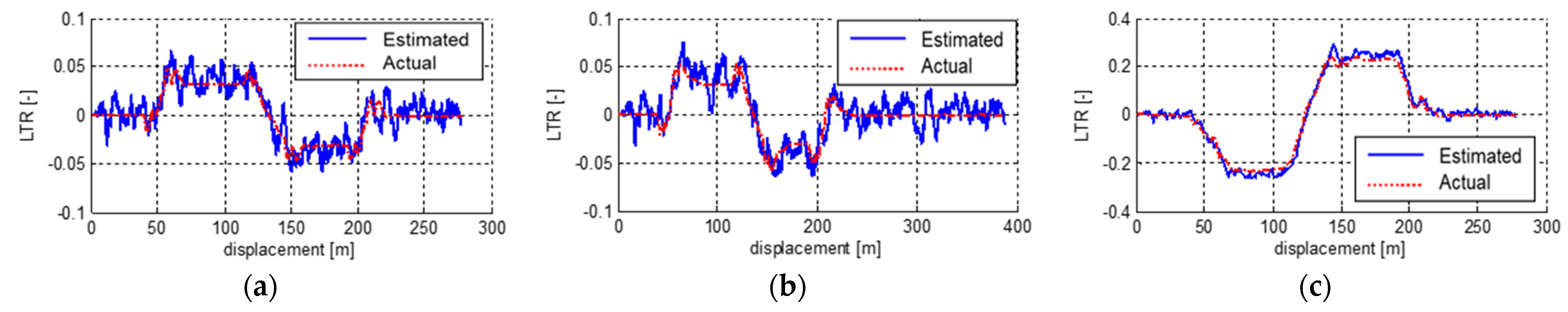
Figure 7.
Estimated bank angle. (a,b) refer to the straight road with the bank angle condition, and (c) refers to the S-curve with the road bank angle condition.
Figure 7.
Estimated bank angle. (a,b) refer to the straight road with the bank angle condition, and (c) refers to the S-curve with the road bank angle condition.
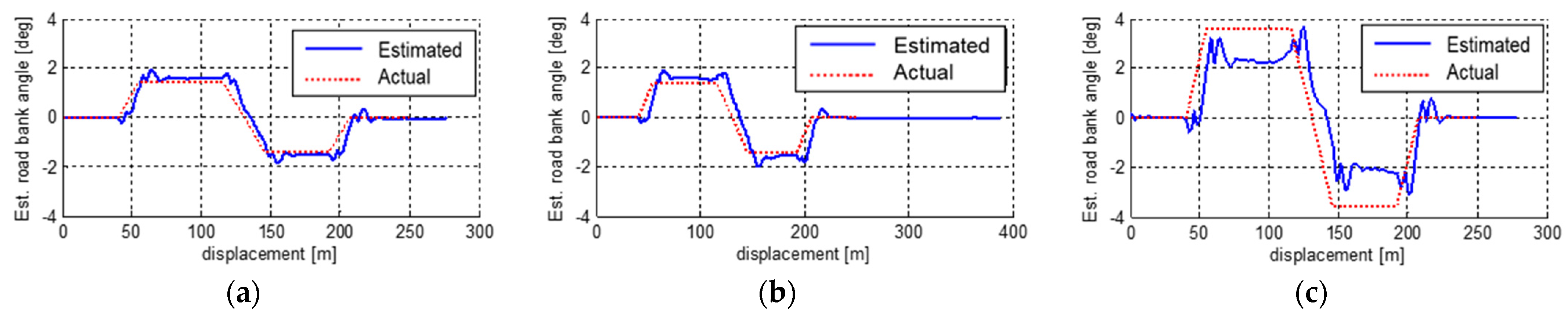
Figure 8.
Rollover principle test using equipment of commercial vehicle ESC.

Publisher’s Note: MDPI stays neutral with regard to jurisdictional claims in published maps and institutional affiliations. |
© 2021 by the authors. Licensee MDPI, Basel, Switzerland. This article is an open access article distributed under the terms and conditions of the Creative Commons Attribution (CC BY) license (https://creativecommons.org/licenses/by/4.0/).
Share and Cite
MDPI and ACS Style
Shin, D.; Woo, S.; Park, M. Rollover Index for Rollover Mitigation Function of Intelligent Commercial Vehicle’s Electronic Stability Control. Electronics 2021, 10, 2605. https://doi.org/10.3390/electronics10212605
AMA Style
Shin D, Woo S, Park M. Rollover Index for Rollover Mitigation Function of Intelligent Commercial Vehicle’s Electronic Stability Control. Electronics. 2021; 10(21):2605. https://doi.org/10.3390/electronics10212605
Chicago/Turabian StyleShin, Donghoon, Seunghoon Woo, and Manbok Park. 2021. "Rollover Index for Rollover Mitigation Function of Intelligent Commercial Vehicle’s Electronic Stability Control" Electronics 10, no. 21: 2605. https://doi.org/10.3390/electronics10212605
Note that from the first issue of 2016, this journal uses article numbers instead of page numbers. See further details here.