Article

Design and Experiments of the Sheet Electron Beam Transport with Periodic Cusped Magnetic Focusing for Terahertz Traveling-Wave Tubes

1
National Key Laboratory of Science and Technology on Vacuum Electrics, Beijing Vacuum Electrics Research Institute, Beijing 100015, China
2
Institute of Nano-Photoelectronics and High Energy Physics, Beijing Institute of PetroChemical Technology, Beijing 102617, China
3
National Key Laboratory of Science and Technology on Vacuum Electronics, University of Electronic Science and Technology of China, Chengdu 610054, China
*
Author to whom correspondence should be addressed.
Electronics 2021, 10(24), 3051; https://doi.org/10.3390/electronics10243051
Submission received: 9 November 2021 / Revised: 1 December 2021 / Accepted: 3 December 2021 / Published: 7 December 2021
(This article belongs to the Special Issue High-Frequency Vacuum Electron Devices)

Abstract

:
The successful transport of a sheet electron beam under the periodic cusped magnet (PCM) focusing at the terahertz frequencies is reported. The sheet beam with a current density of 285 A/cm2 is intended for the developing G-band sheet-beam traveling-wave tube (TWT) whose operating voltage is nominally 24.5 kV. A beamstick was developed to validate the design of the electron optics system, which is considered as the most challenging part for developing a sheet-beam device. A beam transmission ratio of 81% is achieved over a distance of 37.5 mm at a cathode voltage of −25.0 kV. The total current and the collector current were measured to be 125 and 102 mA, respectively. The experimental results are promising, demonstrating that the PCM scheme is capable of focusing a high-current-density sheet beam and hence can find use in the terahertz TWTs, offering the advantages of compact size and light weight.

1. Introduction

The sheet electron beam has been long considered for enhancing the performance of vacuum electronic devices (VEDs). However, the development of a sheet-beam device has been hindered for decades due to the difficulties in transport known as the “diocotron instability” [1,2]. Significant breakthroughs have been made in the last ten years. Several prototype devices have been successfully developed [3,4,5,6,7], which demonstrates the great potential of the sheet-beam technology, especially in power enhancement. Those inventions in many ways represent state-of-the-art technologies of developing VEDs except that most of them are based on solenoidal magnetic fields generated by the permanent magnets [8,9] whose volume and weight increase dramatically as the magnetic field peak and the transport distance increased. This is a major concern for using the sheet beam in a practical scenario such as the airborne radars and communication applications. Therefore, the periodic permanent magnet (PPM) focusing of the sheet beam is still attractive, although its application is found to be limited to transporting a sheet beam with low voltage and high current density [9].
The PCM focused sheet-beam TWT was first demonstrated at Ka band with beam transmission of 93% with a voltage of 24.3 kV [10]. At the same frequency band, a PCM-focused high-power sheet-beam TWT was recently reported [11] with a CW power output of up to 3 kW, along with a transmission of 97% at a voltage of 30.9 kV and a current of 0.82 A. In addition, a W-band PCM-focused sheet-beam extended-interaction oscillator (EIO) was demonstrated with a transport of 94.4% at a high operating voltage of ~47 kV [12]. However, it remains a challenge for the PCM scheme to transport a low-voltage high-current-density sheet beam for the terahertz TWTs. The reasons come from both the insufficient capacity of the magnet material itself and the structural limitations from the reduced size of the circuit. Thus, compromises have to be made between the desired the high current and the achievable magnetic fields. We recently performed a theoretical review of the PCM focusing, along with the design of a magnetic field system [13]. As a key step of developing the sheet-beam TWT, a beamstick was developed. This paper presents a complete design of the electron optical system. The experimental results are also reported for the first time.

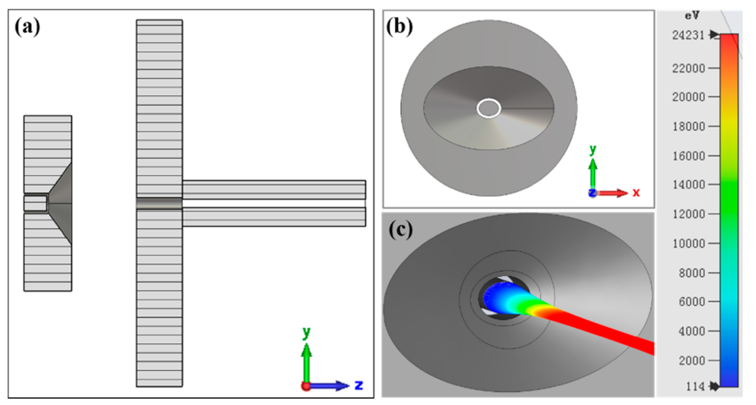
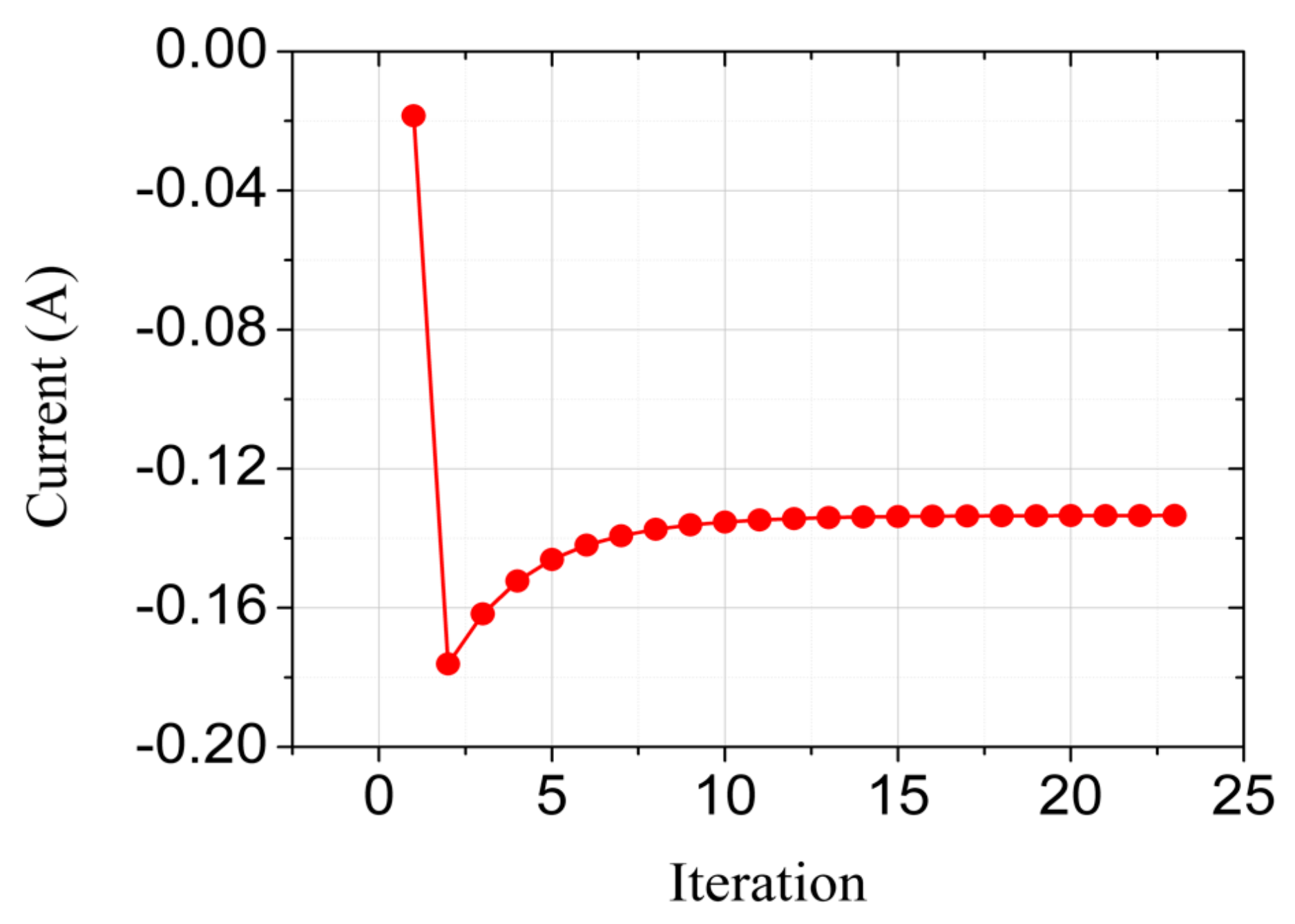
2. Design of the Electron Gun

The design of the electron gun was based on the CST (Computer Simulation Technology) Particle Tracking Solver. The nominal design parameters are listed in Table 1. The simulation model is shown in Figure 1. Basically, this is a Pierce-type gun with the exception that the cross sections of the cathode and the focusing electrode are conformal ellipses, as shown in Figure 1b. To facilitate the assembly, the shape of the electrodes is designed as simply as possible. Consequently, both the cathode emission surface and the anode entrance are planar. In the tracking simulation, we enable the gun iteration option to ensure the convergence of the emitting current. The effects of the space-charge field and the self-magnetic field of the beam are also considered in the simulation. The 2D particle monitors were deployed along the beam transport direction with an interval of 0.1 mm. As a result, the position and other statistical information of the particles can be derived by these monitors.
Figure 2 shows the convergence of the emitting current. The simulation predicted a current of 135 mA at a cathode voltage of 24.5 kV. The resulting cathode loading is 31.1 A/cm2, which exceeds the capacity of the ordinary M-type cathodes. Thus, the scandate cathode is used.
Figure 3 shows the electrostatic trajectory envelopes of the sheet beam. We can see that the gun provides an excellent laminar property for the sheet beam. The electron beam is compressed in both directions. However, the major contribution to the compression ratio comes from the vertical direction (Y). The position of the beam waist in the vertical direction is basically the same as that in the horizontal direction, which is about 7.8 mm. The compression ratios of the horizontal and vertical directions are 1.37 and 6.5, respectively, corresponding to an overall area compression ratio of 8.9. Figure 4 demonstrates the phase space of the compressing process where the two cross sections correspond to the emission surface and the beam waist, respectively. We can see that the sheet beam maintains its shape well during the compressing process, and no over-compressed phenomenon is observed at the edges of the beam.

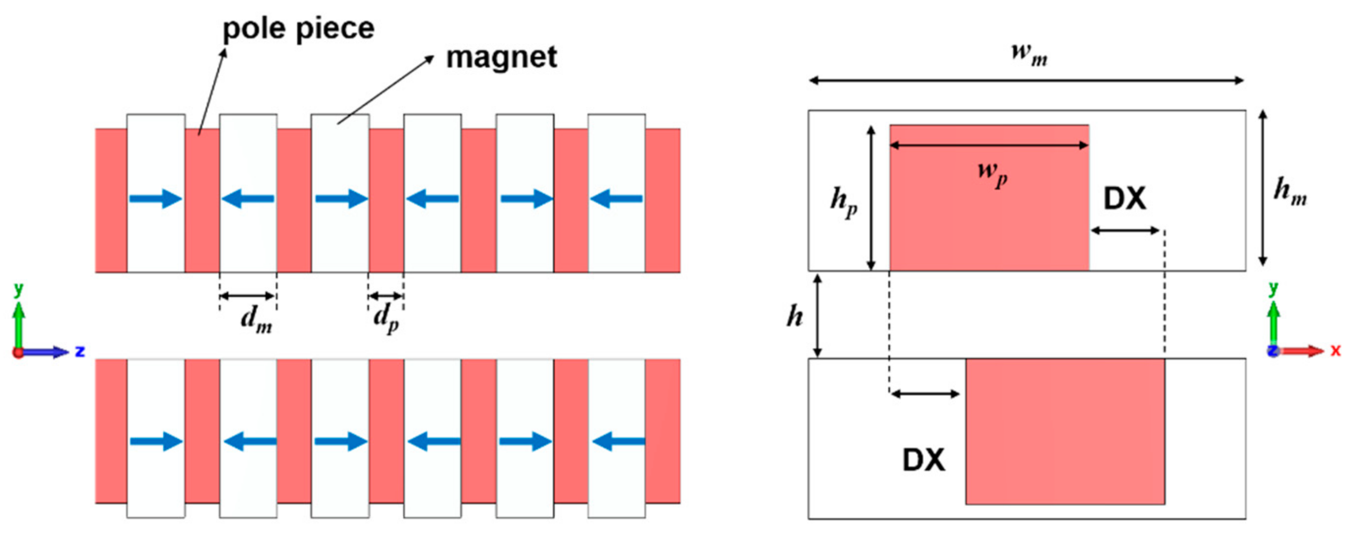
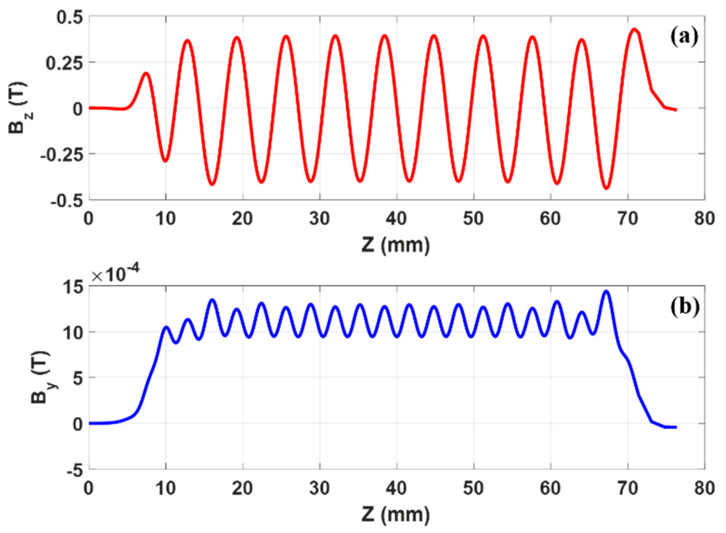
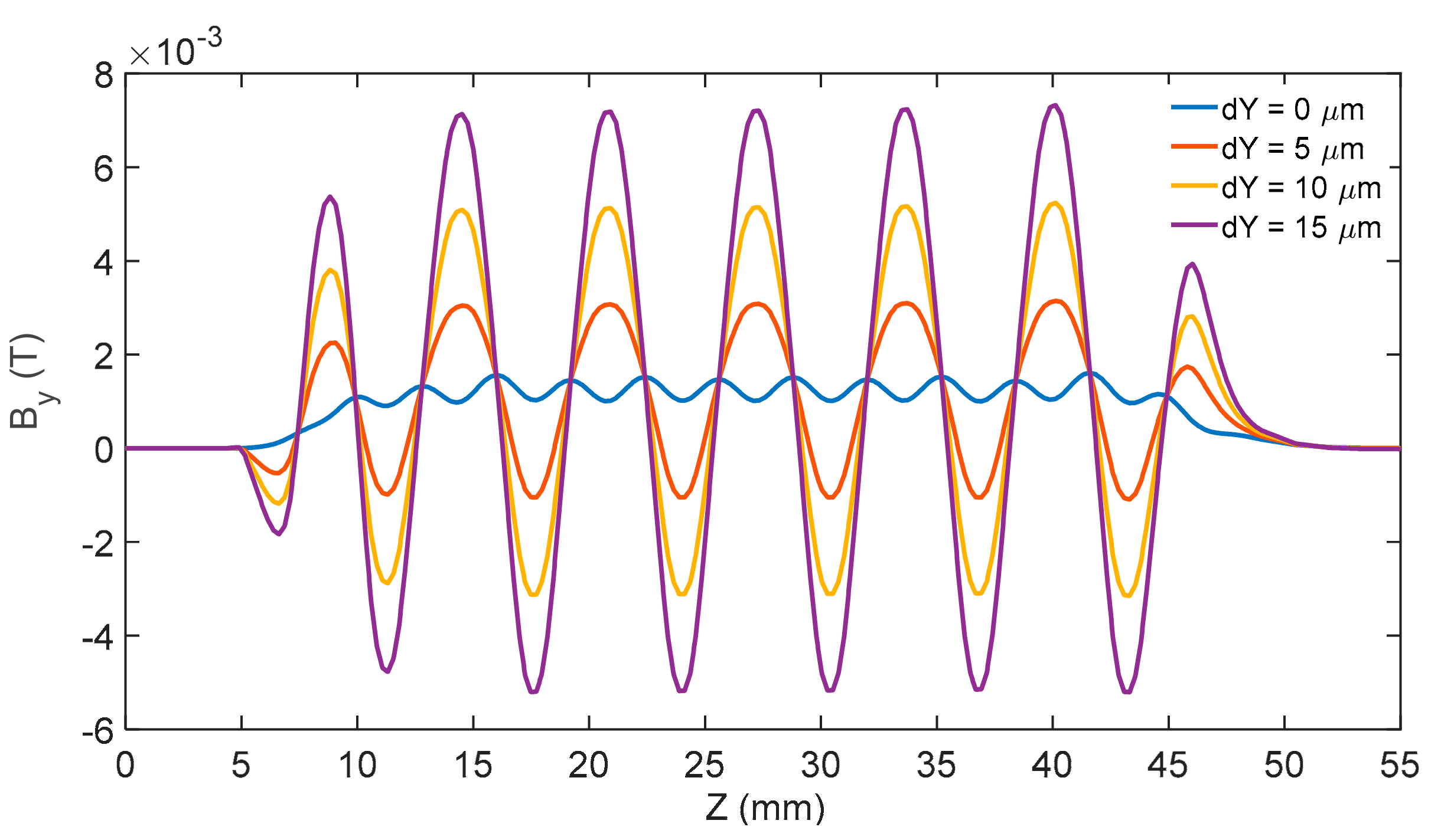
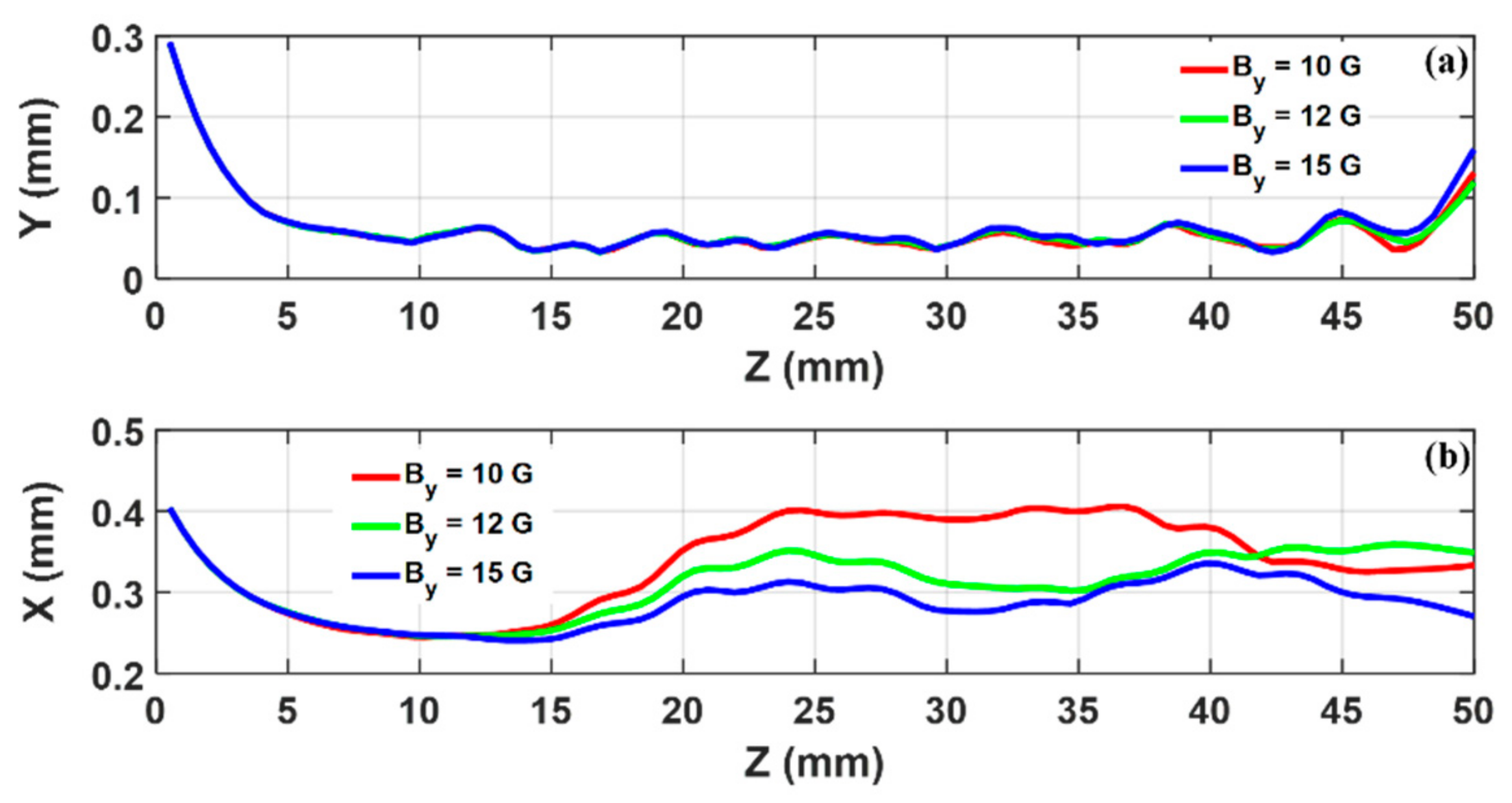
3. Design of the PCM Focusing System

The stable transmission of the sheet beam under the periodically focusing magnetic fields requires the two-plane focusing, i.e., both the vertical and the horizontal directions need to be considered. Several focusing schemes can realize that. Here, a modified offset-pole-piece PCM scheme [13] is used. The model of the focusing system is shown in Figure 5. The arrows in the magnets denote the direction of the magnetization. The CST Magnetostatic Solver was used for the design of the magnet system. The parameters of the magnetic system are listed in Table 2. In the simulation, the iron material is assumed for the pole pieces with a nonlinear BH relationship.
Figure 6a shows the distribution of the on-axis magnetic field Bz. It can be seen that a peak of 0.38 T is achieved. Figure 6b plots the distribution of By along the longitudinal direction at the beam sides X = ±0.3 mm and Y = 0. This magnetic field is denoted as the side magnetic field By,side. We can see that it is essentially a dc field, which is different from Bz. Thus, the mechanism for horizontal focusing is different from that of the vertical focusing. The theory predicted that a value of 103 T for By is required to counter the space-charge defocusing effect from Esp,x. We can see from Figure 6b that the design meets the requirement.
The unique distribution of By,side is highly sensitive to the position, as is illustrated in Figure 7, where dY denotes the position deviation from the Y = 0 plane with X = 0.3 mm constant. It can be seen that the distribution of By,side varies dramatically. For this reason, a means of tuning the side magnetic field is critical in practice.
By importing the designed magnetic fields into the electron gun model, a complete electron optical simulation can be achieved. Figure 8 shows the formation and transmission of the sheet beam under the designed focusing magnetic fields. It can be seen that the sheet beam is well confined in both directions. Moreover, although the horizontal envelope of the sheet beam is highly sensitive to the side magnetic field, the vertical focusing is nearly independent of the side focusing. This is the basis of tuning the side magnetic field in practice.
In light of the importance of the magnetic field system, efforts have been made to measure the magnetic field distributions. The measuring platform is demonstrated in Figure 9a. This is a three-dimensional auto-measuring platform, which can provide a position-shifted accuracy of 10 μm and a magnetic field measurement accuracy of 10−6 T. The results are shown in Figure 9b,c with simulation results compared. Note that since the space between the two magnet arrays is too small to insert the probe in terms of the design value of h = 3.0 mm, we have to enlarge the space. As a result, the peak of the magnetic fields was reduced. However, we can see that the measured distribution of Bz is in good agreement with the simulation. Although discrepancy can be observed in By, the agreement is fair considering the sensitivity of the side magnetic field.

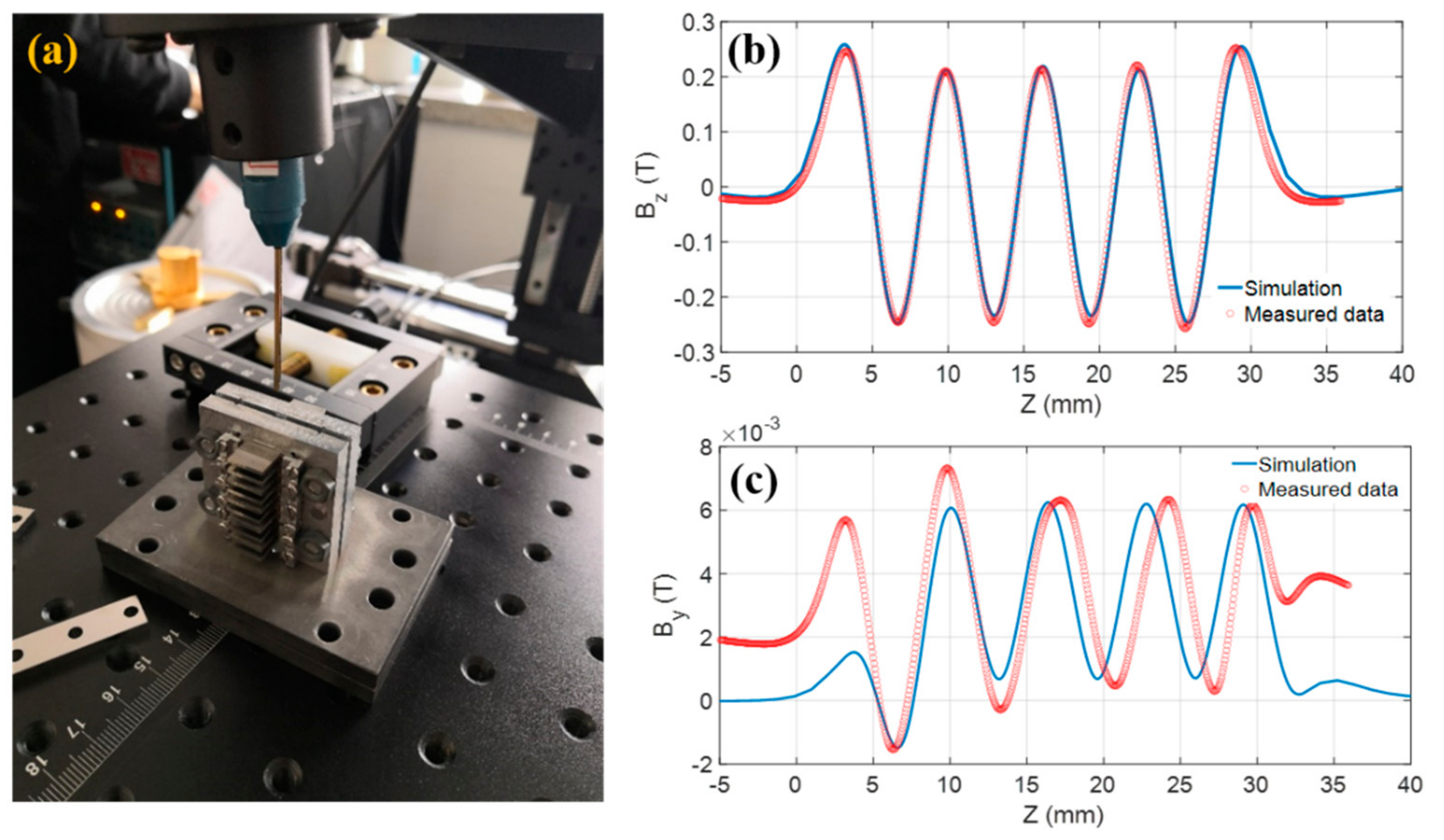
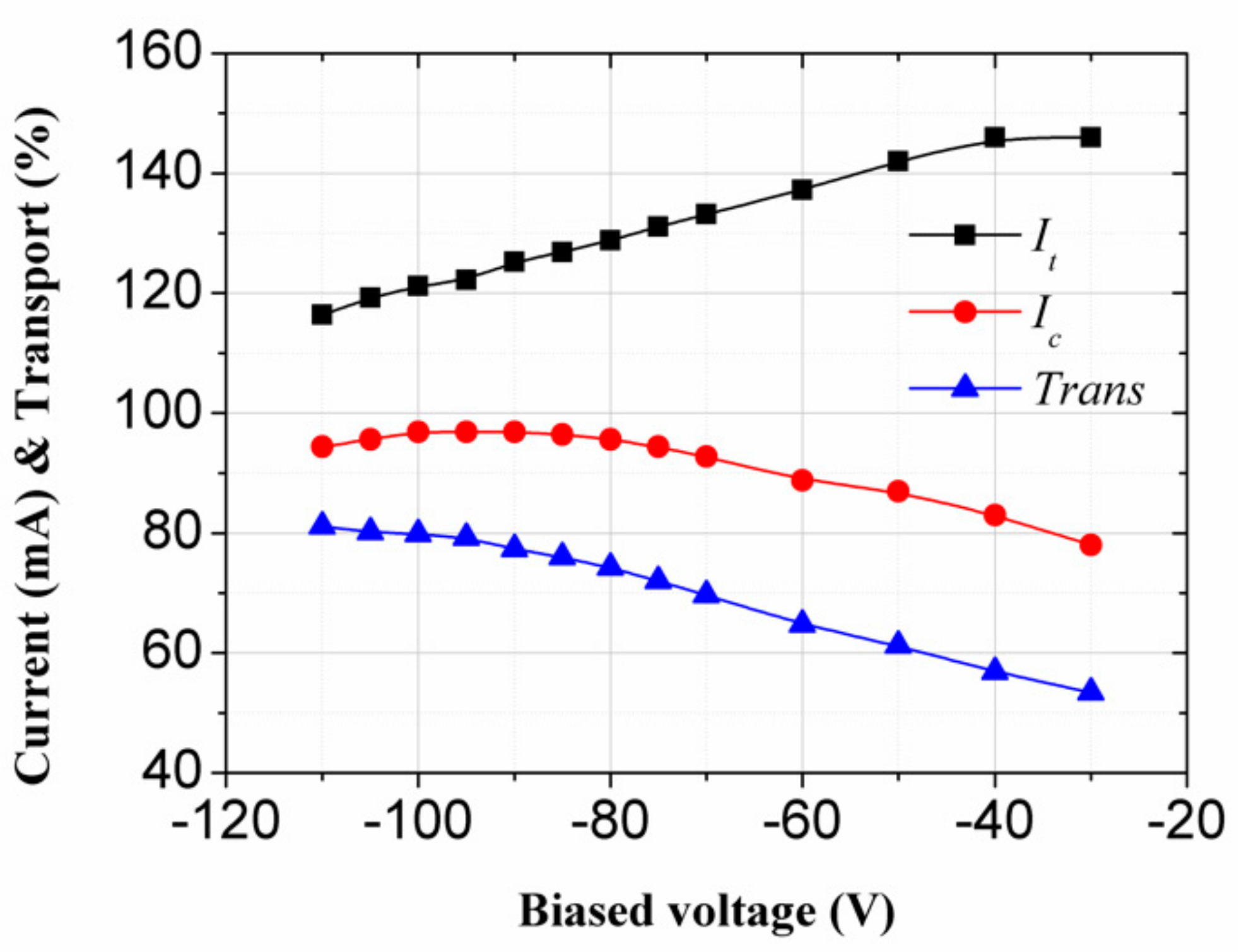
4. Experimental Results

Experiments have been carried out to verify the design of the sheet-beam electron optical system. A beamstick was assembled without the need for RF input/output coupler, where the interaction circuit is replaced by a rectangular tunnel of 0.75 × 0.2 mm2. The tunnel size is consistent with that of an actual interaction circuit. The transmission distance is 37.5 mm from the anode entrance to the collector. Such a distance is sufficient to support an amplification up to 18 dB.
Figure 10 demonstrates the beamstick in the testing site. The performance of the beamstick was measured under the pulse mode with pulse durations of 10–50 μs and repetition rates of 100 Hz. The body and the collector currents are measured by the ammeters and simultaneously confirmed with the oscilloscope. Figure 11 shows current waveforms for different pulse durations.
Figure 12 plots the measured cathode emission current. At 1050 °C, corresponding to a filament heating power ~4.4 W, the emission current was measured to be 125 mA, corresponding to a cathode loading of 28.8 A/cm2. The current is slightly lower than the design value of 135 mA due to the biased voltage applied to the focus electrode. By reducing the biased voltage, the emission can approach 146 mA. Thus, the scandate cathode can provides sufficient emission for the sheet-beam gun.
Figure 13 shows the total current It and the collector current Ic as a function of the cathode voltage. It can be seen that the total current It increases almost linearly with the increase of the cathode voltage. The collector current Ic is small and rises slowly when the voltage is less than 18 kV, but it increases fast after that. An optimal transport efficiency over 81% was obtained at a voltage of −25 kV, which is slightly higher than the design value of −24.5 kV. The corresponding total current and collector current are 125 and 102 mA, respectively.
From the measured currents, we can estimate that the cutoff voltage of the PCM system is about 19 kV. Such a high cutoff voltage, which is close to the nominal operating voltage (24.5 kV), indicates that the PCM system may approach its limit of capacity. That is why the voltage corresponding to the optimal transport efficiency is higher than the nominal operating voltage. Due to the difficulty in achieving a higher peak of the magnetic field system, the voltage has to be increased to achieve the optimal transport efficiency.
Figure 14 shows the effect of the biased focus voltage (BFV) on the currents and the transport efficiency. It can be seen that both the collector current and the transport efficiency are significantly increased as the BFV increased before it reaches −85 V. As the BFV goes further, the increase of the transport efficiency is mainly attributed to the decrease of the total current. Due to the thermal expansion effect of the cathode and the inevitable errors in assembling, the required BFV is found to be much higher than expected. This is also the reason that the total current is lower than the design value at the nominal voltage of 24.5 kV.
Table 3 compared the beam parameters and the transport efficiencies of the sheet-beam TWTs, which were reported with the experimental results. To make the comparison meaningful for different frequencies, the normalized transport distance was used, which is defined as L0, where λ0 = c/f0, L is the actual transmission distance, f0 is the central frequency, and c is the speed of light in vacuum. We specify f0 as 14, 35, 44, 94, and 220 GHz for the Ku, Ka, Q, W, and G band. It can be seen clearly from the table that this paper demonstrated the highest level in the cathode emitting capacity, beam current density, and normalized transport distance among the PCM focused TWTs. In particular, the transmission current density is nearly five times higher than that of the Ka-band TWT. Considering the more stringent requirements for tolerance in terahertz frequencies, we can conclude that a substantial breakthrough has been made in the long-distance transmission of the PCM focused sheet beam. The focusing with a permanent magnet solenoid allows a higher current density because a very large magnetic field (0.85~1 T) can be achieved. However, the disadvantages in volume and weight limit the use of a permanent magnet solenoid in TWTs.

5. Conclusions

Efforts have been made in the design, fabrication, assembly, and measurement to achieve a PCM-focused sheet electron beam for the terahertz TWTs. A beamstick was developed and tested. A transport efficiency over 81% was measured with a total current of 125 mA and a collector current of 102 mA. The total current is slightly lower than the design value due to an increased focus voltage. Although such a current is still at an intermediate level for a sheet beam, it is two times higher than that of a circular beam with PPM focusing at the same frequencies. Thus, the performance enhancement of the TWT with a sheet beam can be expected.

Author Contributions

Conceptualization, C.Z. and J.F.; methodology, C.Z., P.P., and J.C.; software, S.L.; validation, C.Z., P.P., and J.C.; data curation, X.C., S.S., B.S., and Y.L.; writing—original draft preparation, C.Z.; writing—review and editing, J.F. and C.Z.; supervision, J.F.; project administration P.P., J.C and Y.G. All authors have read and agreed to the published version of the manuscript.

Funding

This research was funded by the Natural Science Foundation of China (Grant No. 62131006, 61921002, 61831001, 92163204) and the Beijing Natural Science Foundation (Grant No. 1192007), The Scientific Research Project of Beijing Educational Committee under Grant KM202010017010.

Conflicts of Interest

The authors declare no conflict of interest.

References

  1. Cutler, C.C. Instability in Hollow and Strip Electron Beams. J. Appl. Phys. 1956, 27, 1028–1029. [Google Scholar] [CrossRef]
  2. Booske, J.H.; McVey, B.D.; Antonsen, T.M. Stability and confinement of nonrelativistic sheet electron beams with periodic cusped magnetic focusing. J. Appl. Phys. 1993, 73, 4140–4155. [Google Scholar] [CrossRef] [Green Version]
  3. Pasour, J.; Wright, E.; Nguyen, K.T.; Balkcum, A.; Wood, F.N.; Myers, R.E.; Levush, B. Demonstration of a Multikilowatt, Solenoidally Focused Sheet Beam Amplifier at 94 GHz. IEEE Trans. Electron. Devices 2014, 61, 1630–1636. [Google Scholar] [CrossRef]
  4. Gamzina, D.; Himes, L.G.; Barchfeld, R.; Zheng, Y.; Popovic, B.K.; Paoloni, C.; Choi, E.; Luhmann, N.C. Nano-CNC Machining of Sub-THz Vacuum Electron Devices. IEEE Trans. Electron. Devices 2016, 63, 4067–4073. [Google Scholar] [CrossRef]
  5. Pershing, D.E.; Myers, R.E.; Levush, B.; Nguyen, K.T.; Abe, D.K.; Wright, E.; Larsen, P.B.; Pasour, J.; Cooke, S.; Balkcum, A.; et al. Demonstration of a Wideband 10-kW Ka-Band Sheet Beam TWT Amplifier. IEEE Trans. Electron. Devices 2014, 61, 1637–1642. [Google Scholar] [CrossRef]
  6. Cusick, M.; Atkinson, J.; Balkcum, A.; Caryotakis, G.; Gajaria, D.; Grant, T.; Meyer, C.; Lind, K.; Perrin, M.; Scheitrum, G.; et al. X-Band Sheet Beam Klystron (XSBK). In Proceedings of the 2009 IEEE International Vacuum Electronics Conference, Rome, Italy, 28–30 April 2009; pp. 296–297. [Google Scholar] [CrossRef]
  7. Zhao, D.; Lu, X.; Liang, Y.; Yang, X.; Ruan, C.; Ding, Y. Researches on an X-Band Sheet Beam Klystron. IEEE Trans. Electron. Devices 2013, 61, 151–158. [Google Scholar] [CrossRef]
  8. Pasour, J.; Nguyen, K.; Wright, E.; Balkcum, A.; Atkinson, J.; Cusick, M.; Levush, B. Demonstration of a 100-kW Solenoidally Focused Sheet Electron Beam for Millimeter-Wave Amplifiers. IEEE Trans. Electron. Devices 2011, 58, 1792–1797. [Google Scholar] [CrossRef]
  9. Nguyen, K.T.; Pasour, J.A.; Antonsen, T.M.; Larsen, P.B.; Petillo, J.J.; Levush, B. Intense Sheet Electron Beam Transport in a Uniform Solenoidal Magnetic Field. IEEE Trans. Electron. Devices 2009, 56, 744–752. [Google Scholar] [CrossRef]
  10. Shi, X.; Wang, Z.; Tang, T.; Gong, H.; Wei, Y.; Duan, Z.; Tang, X.; Wang, Y.; Feng, J.; Gong, Y. Theoretical and Experimental Research on a Novel Small Tunable PCM System in Staggered Double Vane TWT. IEEE Trans. Electron. Devices 2015, 62, 4258–4264. [Google Scholar] [CrossRef]
  11. Wang, J.; Wan, Y.; Li, X.; Liu, Q.; Li, H.; Yao, Y.; Zheng, Q.; Wu, Z.; Jiang, W.; Liu, G.; et al. Continuous Wave Operation of a Ka-Band Broadband High-Power Sheet Beam Traveling-Wave Tube. IEEE Electron. Device Lett. 2021, 42, 1069–1072. [Google Scholar] [CrossRef]
  12. Wang, J.; Li, X.; Rui, L.; Liu, Z.; Liu, G.; Jiang, W.; Wu, Z.; Hu, Y.; Luo, Y. Experimental Study of a 6 kW W-band PCM Focused Sheet Beam EIO. In Proceedings of the 2019 International Vacuum Electronics Conference (IVEC), Busan, Korea, 28 April–1 May 2019; pp. 1–2. [Google Scholar]
  13. Zhang, C.; Feng, J.; Cai, J.; Pan, P.; Su, S.; Gong, Y. Focusing of the Sheet Electron Beam with Two-Plane Periodic Cusped Magnetic System for Terahertz TWTs. IEEE Trans. Electron. Devices 2021, 68, 3056–3062. [Google Scholar] [CrossRef]
  14. Wang, J.; Liu, G.; Shu, G.; Zheng, Y.; Yao, Y.; Luo, Y. The PCM focused millimeter-wave sheet beam TWT. In Proceedings of the 2017 Eighteenth International Vacuum Electronics Conference (IVEC), London, UK, 24–26 April 2017; pp. 1–3. [Google Scholar]
Figure 1. The CST model of the sheet-beam electron gun: (a) the cross section of the model, (b) the front view of the cathode and focus electrode, and (c) the beam formation with the elliptical focus electrode.
Electronics 10 03051 g001
Figure 2. The convergence of the emitting current.
Electronics 10 03051 g002
Figure 3. The envelopes of the electrostatic trajectories of the sheet beam.
Electronics 10 03051 g003
Figure 4. Compression of the sheet beam from emission surface to the waist.
Electronics 10 03051 g004
Figure 5. Schematic diagram of the PCM focusing system.
Electronics 10 03051 g005
Figure 6. Design results of the focusing magnetic fields: (a) the on-axis distribution of Bz, (b) the side magnetic field By,side at X = ±0.3 mm and Y = 0.
Electronics 10 03051 g006
Figure 7. Sensitivity analysis of the side magnetic field By,side.
Electronics 10 03051 g007
Figure 8. Simulations of the sheet beam transmission under the designed focusing magnetic fields with the side magnetic field By,side varied: (a) the trajectories envelopes in vertical direction and (b) the trajectories envelopes in horizontal direction.
Electronics 10 03051 g008
Figure 9. (a) The magnetic field measurement platform, (b) the measured axial magnetic field distribution Bz, and (c) the measured side magnetic field By.
Electronics 10 03051 g009
Figure 10. The beamstick in the testing site.
Electronics 10 03051 g010
Figure 11. The current waveforms measured by oscilloscope with (a) pulse durations of 10 μs and (b) pulse durations of 50 μs. Both cases have the same repetition rates of 100 Hz.
Electronics 10 03051 g011
Figure 12. The emission current of the Scandate cathode as a function of the filament power.
Electronics 10 03051 g012
Figure 13. The measured currents as a function of the cathode voltage.
Electronics 10 03051 g013
Figure 14. The measured current and the transport efficiency as a function of the biased focus voltage.
Electronics 10 03051 g014
Table 1. Design parameters of the sheet-beam electron gun.
ParametersValue (Unit)
Cathode voltage V024.5 kV
Emission current I00.135 A
Cathode size0.85 × 0.65 mm2
Beam waist size 10.6 × 0.11 mm2
Tunnel size0.8 × 0.2 mm2
1 The cross section of the beam is an ellipse. Thus, the dimension of beam is determined by the major axis and the minor axis of the ellipse.
Table 2. Parameters of the magnet system.
ParametersValue (Unit)
Br1.09 T
Lm6.4 mm
h3.0 mm
wm × hm × dm15 × 5.5 × 2.0 mm3
wp × hp × dp6.8 × 5.0 × 1.2 mm3
Table 3. Comparison of the electron optical parameters of the sheet-beam TWTs, which were reported with experimental results.
DevicesBandFocusing SchemeVoltage (kV)Current (A)Beam Size and Cathode SizeCathode Loading
(A/cm2)
Current Density
(A/cm2)
Normalized Transport DistanceTransport Efficiency (%)
This paperGPCM24.50.1350.60 × 0.11 mm2
0.85 × 0.65 mm2
31.128527.581
TWT [10]KaPCM24.30.83.2 × 0.6 mm2
3.2 × 1.8 mm2
17.6853.0513.1693
TWT [11]KaPCM30.90.824.0 × 0.4 mm2
1 10:1
6.36663.661797
TWT [14]KuPCM3448.0 × 0.9 mm2
10:1
7.07370.731481
TWT [14]QPCM301.23.0 × 0.4 mm2
10:1
12.73127.31792
Beamstick [3,5,8]W/KaSolenoid 22044 × 0.25 mm2
4 × 10 mm2
104006.2798.5
TWT [4]GSolenoid22.880.230.7 × 0.1 mm2
0.86 × 1.06 mm2
3843829.3578.3
1 The dimensions of the cathode cannot be found but the compression ratios were given. 2 Permanent magnet solenoid.
Publisher’s Note: MDPI stays neutral with regard to jurisdictional claims in published maps and institutional affiliations.

