
Mobile Collectors for Opportunistic Internet of Things in Smart City Environment with Wireless Power Transfer


1
School of Science, Technology and Engineering, The University of Sunshine Coast, Moreton Bay Campus, 1 Moreton Parade, Petrie, QLD 4502, Australia
2
School of Engineering and Information Technology, The University of New South Wales, Sydney, NSW 2052, Australia
*
Author to whom correspondence should be addressed.
Electronics 2021, 10(6), 697; https://doi.org/10.3390/electronics10060697
Submission received: 23 December 2020
/
Revised: 3 March 2021
/
Accepted: 9 March 2021
/
Published: 16 March 2021
(This article belongs to the Special Issue Emerging Technologies for Computer, Electrical and Systems Engineering)
Abstract
:In the context of Internet of Things (IoT) for Smart City (SC) applications, Mobile Data Collectors (MDCs) can be opportunistically exploited as wireless energy transmitters to recharge the energy-constrained IoT sensor-nodes placed within their charging vicinity or coverage area. The use of MDCs has been well studied and presents several advantages compared to the traditional methods that employ static sinks. However, data collection and transmission from the hundreds of thousands of sensors sparsely distributed across virtually every smart city has raised some new challenges. One of these concerns lies in how these sensors are being powered as majority of the IoT sensors are extremely energy-constrained owing to their smallness and mode of deployments. It is also evident that sensor-nodes closer to the sinks dissipate their energy faster than their counterparts. Moreover, battery recharging or replacement is impractical and incurs very large operational costs. Recent breakthrough in wireless power transfer (WPT) technologies allows the transfer of energy to the energy-hungry IoT sensor-nodes wirelessly. WPT finds applications in medical implants, electric vehicles, wireless sensor networks (WSNs), unmanned aerial vehicles (UAVs), mobile phones, and so on. The present study highlights the use of mobile collectors (data mules) as wireless power transmitters for opportunistic IoT-SC operations. Specifically, mobile vehicles used for data collection are further exploited as wireless power transmitters (wireless battery chargers) to wirelessly recharge the energy-constrained IoT nodes placed within their coverage vicinity. This paper first gives a comprehensive survey of the different aspects of wireless energy transmission technologies—architecture, energy sources, IoT energy harvesting modes, WPT techniques and applications that can be exploited for SC scenarios. A comparative analysis of the WPT technologies is also highlighted to determine the most energy-efficient technique for IoT scenarios. We then propose a WPT scheme that exploits vehicular networks for opportunistic IoT-SC operations. Experiments are conducted using simulations to evaluate the performance of the proposed model and to investigate WPT efficiency of a power-hungry opportunistic IoT network for different trade-off factors.
1. Introduction
Data collection and transmission operations are often marred because of the finite node-lifetime of a WSN. And since this operation is purely energy-dependent and indeed energy-constrained sensor-nodes with limited battery power cannot smoothly transmit their data to the access point, it has become a fundamental operational bottleneck. Hence, for an efficient data aggregation and transmission, it is desirable for the sensor-nodes to be energy-efficient. However, due to the fact that IoT sensors are energy-constrained as a result of their smallness and mode of deployments across different operating environments as well as the very large costs of battery replacements, batteries are therefore employed in powering the sensors as direct power transfer from the grid is not feasible [1,2]. Research has also revealed that nodes closely attached to the sinks usually discharge their power so quickly and are mostly energy constrained, because of their frequent data forwarding activity. Sensor-nodes are low-power and low-cost devices characterized with multifunctional capabilities and are sparsely and randomly distributed across a WSN [1]. Sensor-nodes are also characterized with four basic modules: sensing, processing, transceiver, and power units.
Due to limited battery capacity of a sensor-node, a WSN does not remain operational in perpetuity. To prolong the lifetime of a senor network, many techniques have emerged; the most common being the energy harvesting (EH) technique [3,4,5,6,7]. The EH technique heavily relies on the energy-extraction from the environment. The success of this scheme for sensor networks remains limited in operation because the proper operation of an EH scheme is environmentally-dependent. The natural sources of energy harvesting such as sunlight (for solar energy) have shown several limitations and cannot be employed to charge IoT network sensors due to the stochastic mode of their energy arrivals and their seeming non-availability when needed [3,4,5]. Wireless RF power transmitter leverages on this shortcoming and presents as an alternative source of power to the IoT sensors. Compared to the natural energy harvesting model, the wireless RF power transfer presents several advantages including flexibility in sensor placement planning, easily controllable, more reliable, and easily managed [2].
A sensor network in a smart city is characterized by the deployment of several sensor-nodes with various sensing capabilities, communication and computation for application specific analysis [3]. A widely known application classification is the deployment of battery-powered sensor-nodes across even the most difficult areas. A battery-powered sensor-node has the huge limitation of finite node lifetime. Nodes arbitrarily cease to operate when their batteries are depleted thereby leading to low duty-cycle or reduced sensing reliability and low transmission range. Nodes may however choose to possibly use large batteries for longer sensing durations, but this will incur increased size, weight and cost occasioned by higher power requirements [3]. Several solution-techniques are currently trending and relate to how to effectively maximize the network lifetime of battery-powered and energy-hungry sensor-nodes. Some of these are discussed in [3] and are only useful in prolonging the interval of time for battery replacements and by no means guaranteeing perpetual lifetime of the sensor-nodes. Recently, energy harvesting has emerged and has shown some potentials as an alternative technique to address the finite node lifetime challenge. Sudevalayam and Kulkarni [3] define energy harvesting as a technique of acquiring/scavenging energy from the environment or different energy sources and further utilizing the harnessed energy (electrically-converted) to power the sensor nodes to increase their operational lifetime and capability. Despite the successes made using energy scavenging techniques, it has not gone without limitations in the context of sensor network applications. This is because environmental factors such as weather and seasonal constraints heavily determine the energy harvesting operational technique [4,5]. In addition, the size an EH device may trigger deployment issues especially in a situation where the size of the EH device is much larger than the sensor node that it is trying to power.
One of the major limitations of the single data mule scheme is that sensor nodes are battery-powered and highly irreplaceable owing to the very large associated costs and mode of deployments. A major challenge of the data collection and transmission operations of a WSN as depicted in [4,8,9,10,11], is the finite node-lifetime of the WSN, where the sensor-nodes are mostly energy-constrained and require to use energy to transmit their data to the mobile data collectors. This invariably is a fundamental performance bottleneck of the data mule system which tends to minimize the node energy consumption by transferring the transmission protocol overheads at the sensor to the mobile data collectors. One of the major objectives of the present study is to address this challenge—to make WSNs perpetually operational by proposing approaches that tend to replenish the energy of the battery-powered sensors used in data collection and transmission operations. Hence, the need for the proposed WPT technique. By considering both techniques (i.e., exploiting the same data collectors as wireless energy transmitters), we intend to maximize the network lifespan, further minimize the node energy consumption of the sensors, reduce cost of deployments and optimize collection efficiency. Given the constraints on energy supply and data transmission performance of the sensor nodes it is, therefore, important to optimize the energy transfer strategy of the wireless energy transmitters as well as the average energy charged by the sensors. Therefore, our proposed scheme intends to leverage on the advantages of the combinatorial nature of these two identified separate schemes to further minimize cost, prolong the network lifespan and optimize energy efficiency.
The major contributions of this paper are as follows:
- This article is structured to first give a comprehensive review of WPT technologies and applications that can be exploited for SC scenarios and highlights a comparative analysis of the various WPT technologies to determine the most energy-efficient for IoT and WSN applications.
- We closely re-examine the different application models of WPT technologies with the objective of identifying which application is best suited or closely matched with our proposed scheme for IoT-SC applications.
- Leveraging on the advantages of WPT technology, we address a major limitation of the data mule system by proposing a new scheme which exploits the use of MDCs (data mules) for both data collection and wireless energy transmission operations in a SC.
- We conduct an empirical study of WPT model to determine the effect of varying the distance on the power transfer efficiency. We investigate using simulations the WPT efficiency and the average energy charged by the sensors while considering different trade-off factors.
The rest of this paper is organized as follows. Section 2 presents the background and motivation of the study, while Section 3 presents a comprehensive review of WPT technologies that are applicable for IoT/WSN SC scenarios. In Section 4, we present the different application models of WPT technologies. We investigate the WPT efficiency and the average energy charged by the sensor-nodes of a power-hungry opportunistic IoT network by considering different trade-offs. Section 5 presents problem description, formulation and solution, while Section 6 presents simulation results and analysis. Finally, Section 7 concludes the work.
2. Background and Motivation
2.1. Applying Wireless Power Transfer to IoT Technology
Surprisingly, the recent breakthrough in the area of WPT technology shows its high potentials to address the fundamental bottlenecks of finite network lifetime for IoT and WSN applications. Removing this bottleneck implies that IoT nodes can remain perpetually operational [4]. An investigation was made by Xie et al. [4] to determine the operational performance of a network using WPT technology and a given scenario was also presented whereby a vehicle used as a mobile charger periodically moved across the network environment to wirelessly recharge the batteries of the sensor-nodes. In terms of extending the network lifetime of the IoT nodes, authors in [2,4,12,13,14,15,16,17,18,19,20] agree that Wireless Power Transfer has got some promising potentials. It was further shown that by exploiting one of the novel WPT techniques such as magnetic resonant coupling, electric power can be effectively transferred wirelessly within an approximate distance of 2 m from the source energy to the target (receiving energy) [4,13,15,16]. Compared to the energy harvesting technique which opts to locally scavenge energy at a node, WPT makes it a lot easier by using the energy generated elsewhere to periodically recharge the energy-constrained IoT nodes and by avoiding the constraints of wires and plugs. Having seen the breakthrough in WPT technology, authors in [4] sought to address the fundamental question of whether WPT technology has the potentials to keep a WSN perpetually operational through a periodic wireless recharge of the energy-hungry sensors. To this end, the use of a mobile vehicle as a mobile charger that would periodically visit the network and wirelessly recharge the sensors was conceived. By ensuring that each sensor node is energy-filled above the minimum threshold at every instant through a periodic wireless recharge, a WSN may remain perpetually operational [4]. Compared to the energy harvesting technique which is susceptible to environmental factors (such as weather and seasonal constraints), WPT is immune to all these factors and does not require a line of sight (LOS) between the power charger (transmitter) and the target nodes (receivers).
2.2. Applying Opportunistic Mobile Collectors as Mobile Power Chargers
Inspired by the recent breakthrough in WPT technology, this study aims to re-examine the network lifetime model for IoT networks concerned with data aggregation and transmissions. We envision the use of opportunistic mobile vehicles for both data collection and wireless power charging operations. The mobile vehicles (referred here as data mules) will carry power charging systems that can be used to wirelessly charge the IoT nodes while opportunistically traversing the network for data collection from the sensor-nodes. This is fundamentally a scenario that tends to exploit vehicular networks whereby vehicles are used as both mobile data collectors (data mules) and wireless energy transmitters (battery chargers), which traverse the network and wirelessly replenish the energy of the sensor nodes. Thus, data and energy exchange are enabled between the mules (data collectors and energy transmitters) and the sensor nodes (data transmitters and energy receivers). The transmitting node receives power from the mule as it transmits data to the Mule. As long as the data mules are within the vicinity of the sensor nodes, they can collect data and be able to wirelessly charge the nodes. We therefore propose a scheme whereby vehicles can be exploited as data mules for both opportunistic data collection and wireless power charging in order to save cost and optimize efficiency. The separate components of this scheme—(i) mobile data collection using vehicles as data mules and (ii) wireless mobile charging using a wireless charging vehicle (WCV)—have been well studied in [9,10,11,21,22] and [4,12], respectively, and shown to be energy efficient for WSN applications. For instance, the data mule scheme seen in [9,10,11] was used for opportunistic data gathering and distribution for SC solutions. Accordingly, the authors posit that the data mule scheme has the potential to address two major concerns of data collection for WSN, which include monitoring of spatially separated regional areas (unconnected regions) and optimizing energy efficiency of the battery-powered sensor nodes. Essentially, mules can roam over the different regions [9], collect data from the sensors at a good proximity, buffer it and deliver it to the big data collection center or a remote access point (AP) [4,22]. Moreover, the opportunistic style of data collection has been shown to be cost effective with low node-energy consumption value, since the collection protocol overheads are effectively transferred from the sensors to the mules.
At this juncture, it is instructive to note that this paper significantly differs from other surveyed papers discussing only WCV or periodic wireless recharge with a mobile charging vehicle [4]. Our proposed scheme is significantly a type of delay-tolerant network (DTN) that employs different delivery mechanisms including using data mules among others [9]. Although the use of WCV [4,12] or WPT has some similarity to our proposed scheme (i.e., using mobile data collectors as wireless mobile power chargers or energy transmitters), there are however some fundamental disparities between them. Firstly, from the surveyed papers, a WCV is only deployed for wireless power charging and not for data collection and transmission, whereas our proposed scheme opportunistically exploits the duo advantages of using the same mobile data collectors as wireless mobile power chargers or wireless power transmitters (WPTs). This is predicated on the notion that exploiting the same mobile data collectors as wireless mobile power chargers will further minimize the large delay associated with typical DTNs and further optimize collection efficiency and costs. However, because of the opportunistic style of data collection and wireless energy transmission, large delays can be tolerated even as real-time data exchange and energy transmission between the sensor-nodes and the Mules can assume minimal delay-tolerant. Moreover, our proposed scheme is very much concerned with both the network lifetime and data collection efficiency unlike the WCV which is concerned with only the network lifetime. Compared to the traditional WSNs in which data aggregation and transmission are limited as result of battery-constrained sensors with limited lifecycle of operation as a result of high transmission overheads, the lifetime of the sensors in a WPT-based sensor network can be further prolonged by using opportunistic data mules that serve both as mobile data collectors (MDCs) and mobile energy transmitters (METs).
3. Related Works: An Overview of Wireless Power Transfer
The technology behind transferring power wirelessly dated back to the early 20th century and is credited to Nikola Tesla [4,13,16]. Back then, not much progress was witnessed until the early 1990s which saw the need for the re-emergence of WPT with the proliferation of portable electronic devices including laptops, cell phones, and PDAs. Electromagnetic (EM) radiation or radioactive transfer [13], which became suitable for information transmission faced several challenges in terms of power transfer applications, with low efficiency for omnidirectional radiation while unidirectional radiation required no hinderance in the LOS propagation and some costly tracking mechanisms. Recent advances in research present magnetic resonance as a suitable “candidate” for such regular applications ostensibly because of the limited interactions of the communications materials with magnetic fields [13,15]. WPT can be grouped into three [23], namely magnetic resonant coupling, inductive coupling, and electromagnetic (EM) radiation. The traditional magnetic induction coupling has shown good efficiency and ability to transfer power over short ranges (e.g., electric toothbrush [4,15]) but shows decrease in performance over increasing distances [12,15,16]. Due to some strict requirements such as close-range transmission [15], accurate alignment mechanism [16] between the transmitter and the receiver, and uninterrupted LOS [4], most of the WPT technologies at that time that depended on inductive coupling were limited in applications. A current study conducted by [23] shows that EM radiation technology is limited for WSN applications. Chiefly among the key limitations is that omnidirectional radiation is characterized by low efficiency in WPT and requires LOS between the transmitter and the receiver (i.e., there should be no obstruction or obstacles b/w Tx and Rx). The other limitation is the issue of human safety. For inductive coupling, the study shows that it can only work efficiently for short-range transmissions while it presents magnetic resonant coupling as more appropriate for WSN applications. The basic idea behind resonant-coupled WPT technology is to effectively exchange energy by means of creating magnetic coupling between two devices that are tuned to the same resonance frequency [16].
Table 1 shows a comparative summary of the WPT technologies, their applications and drawbacks. Based on the comparative analysis shown in Table 1, the most suitable WPT methods are inductive coupling and magnetic resonant coupling [23]. However, these techniques of WPT are only suitable for short and midrange transmissions respectively.
Wireless sensor network has become part and parcel of the Internet-of-Things (IoT) currently witnessing a wide area of research advancements especially in the area of energy harvesting and consumption. WPT—a product of this research advancement—is one of the major contributory factors for the future mobile networks comprising IoT and smart cities in overcoming the problem of energy-constrained battery-powered sensor-nodes. Typically, WPT is an emerging technology that enables recharging of battery-driven IoT-nodes without the use of plugs and/or wires but perhaps with the use of wireless charging stations (WCS) or WCVs. Sensor-nodes are typically energy-constrained owing to the limited availability of energy sources and recharging, and battery-replacements are no options due to the associated cost implications and/or mode of deployments of the sensor-nodes. One of the major breakthroughs in the emergence of WPT technology is that battery-powered devices can now harness energy from EM waves in the air and be able to recharge their batteries cordlessly even while on the move [24]. With WPT, thousands of sensor-nodes can be deployed across a network at a low cost. Some of the notable applications of WPT as indicated in [23] include mobile phones, medical implants, wireless sensor networks, electric vehicles, and unmanned aerial vehicles. The promising potentials of WPT as well as its interdisciplinary nature have triggered many research conversations around it which are widely studied in various fields. Such studies are well articulated in [2,12,13,14,15,16,17,18,19,20]. Authors in [1] examined the effects of some factors affecting the energy consumption on WSN’s lifespan and performance. Accordingly, these factors include scalability, reliability, load-balancing, latency, collision, reliability, idle listening, over-hearing, and communication [1].

Table 1.
A comparative summary of WPT technologies for IoT scenarios.
| Ref. | WPT Technologies | Advantages | Drawbacks |
|---|---|---|---|
| [12,15,16,23] | Magnetic inductive coupling |
|
|
| [12,15,16,17,23] | Magnetic resonant coupling |
|
|
| [14,15,16] | Microwave Power Transfer (MPT) |
|
|
| [4,19,25] | RF-energy transfer |
|
|
Energy-hungry IoT sensor-nodes within the vicinity of charging coverage may be wirelessly powered electromagnetically using the wireless charging stations (WCS). This was the position of the authors in [12] who suggested the use of WCS to wirelessly transfer energy to the energy-constrained IoT nodes to overcome the challenges inherent in battery-recharging especially for densely populated network of nodes. The deployment of WCS and wireless coverage are restricted due to the limitations in hardware capability and safety issues, thus raising concerns about the different charging patterns of mobile nodes in line with their speeds. It was discovered in [12] that nodes with higher speeds have relatively shorter waiting time to recharge their energy by WCS than their counterparts with lower speeds. WCS makes use of EM wave radiation to wirelessly transfer power to the IoT sensors. Owing to reasons of technological factors and human safety concerns, WCS cannot be used to radiate higher powers of EM waves, thus bringing restrictions to the charging coverage of WCS [12]. To address this problem, multiple copies of WCS can be planted across the entire network but this also has its consequential cost implications. The focus in [12] is on random mobility of the IoT sensor-nodes including their movement-patterns that pave way for energy harvesting despite challenges of limited charging coverage of WCS. This implies that energy harvesting is possible if the sensor-nodes are within the charging coverage of the WCS.
In [5], a mobile energy charger, moving along a pre-planned path, is deployed to wirelessly recharge the energy-hungry sensor-nodes located along its predetermined route using RF-WPT. The mobile energy charger periodically travels along the predetermined route to recharge the sensors. The proposed scheme consists of an off-the-shelf RF transmitter installed on a robotic vehicle and used as a mobile energy charger. Authors in [26] discuss some of the challenges in rectifier design confronting the implementation of WPT and EH solutions and present how the amount of harvested energy is affected by multiband and broadband rectifiers. Safety and security issues surrounding RF-WPT are robustly discussed in [25,27,28,29] where authors propose a simplified safe charger scheduling scheme whereby power chargers are scheduled to recharge the energy-hungry devices without accommodating the risks inherent in RF radiation. The goal is to maximize charging efficiency so that more charging energy can be harvested at a normal threshold value of EM radiation. In [25], authors discussed the vulnerabilities associated with RF-based WPT channel (as there is no encryption or authentication of the wirelessly transmitted energy), thus raising users’ safety and security concerns.
Application of the green cell-less design to RF-WPT network is presented in [6,30]. Green energy is harvested by connecting the access points (APs) with outdoor energy harvesters such as solar panel and wind turbine to harvest and the harvested energy is later used to wirelessly energize the energy-hungry multiple devices via RF signals [6,30]. Cell-less implies that devices will not associate with any base stations (BSs) before commencing information transmission. In this system, also, devices can be fed from multiple sources, thus making it beneficial for energy-constrained devices. However, the performance of this system is limited by the fact that tight restrictions are placed on the extent to which the total transmit power may be increased owing to the dangerous effects of intensity of RF radiation [6,30]. In [5], an off-the-shelf empirical model of RF energy transfer hardware was established, and the platform was used to test the performance of the RF-based WSN. The empirical model focused on joint optimization of path planning and mobile charging scheduling for wireless-powered sensor network (WPSNs).
The design of an RF-WPT opportunistic harvesting (OH) scheme was proposed in [31], which is an improvement in two energy harvesting schemes known as store-then-cooperate (STC) and energy-harvest (EH). This model, which is meant for multiple access relay systems with various signal transmission techniques, assumes that sources and relays are self-powered devices with fitted rechargeable batteries. Essentially, the nodes are powered by an RF-WPT that relies on a dedicated energy beam. Authors in [32] propose an energy-efficient scheduling scheme in software-defined wireless sensor networks (SDWSN) to reduce the energy consumption of the energy transmitters used for charging sensor devices. The basic idea is to minimize the energy consumption of the chargers while adequately feeding the energy-hungry sensor-nodes. SDWSN mechanism is used to determine the optimal placement of the energy transmitters, minimum required number of power transmitters and the scheduling operations of the power chargers. An opportunistic energy scheduling scheme is proposed in [8], which enables an energy gateway with limited power supply to wirelessly transfer energy to sensor-nodes at some favorable channel conditions. Some of the existing design challenges of WPT and EH solutions using rectifier systems are presented in [26]. With these challenges, it is difficult to achieve maximum RF-DC conversion efficiency.
In [33], authors addressed the scheduling problem of data collection and WPT in a rechargeable WSN with the objective of minimizing the packet loss. Scheduling the WPT and data collection has become very critical in order to extend the battery life of the sensor-nodes and to reduce the packet loss. Moreover, inadequate scheduling causes some of the nodes to drain their batteries and have their data buffer overflow, while the other nodes waste their harvested energy which could be used for data transmission operations. Therefore, optimizing the scheduling of WPT and data collection is very critical in order to reduce the hardware cost. The use of unmanned aerial vehicles (UAVs) with microwave power transfer (MPT) capability to remotely recharge the batteries of the sensor-devices and harvest their data was studied in [34,35,36] as a practical means of deploying a large number of wireless powered sensor-nodes into harsh terrains and inaccessible areas. A large-sized UAV can be equipped with lightweight high-capacity rechargeable batteries and solar panels on top of its wings and can be employed in area of interest to collect data from the sensing devices and recharge their batteries. The paper studied the UAV-assisted MPT and data collection, where the instantaneous patrolling velocity of the UAV is optimized along with online decisions of power transfer and data collection. Authors developed an on-board deep Q-network for online scheduling of MPT and data collection to minimize the overall data packet loss, prevent battery drainage and data queue overflow of the sensing devices. Authors relied on two key limitations of the UAV-assisted MPT technique for their proposed scheme, which included that in practical scenarios, energy harvesting and data transmission could be impaired by the movements of the UAV and time-varying channels [34]. Secondly, information about an up-to-date battery level and data queue length of the ground sensors is not always available to the UAV.
The proposed architecture combines the concepts of cyber physical systems (CPS), the embedded systems and data communication systems. The layout is designed to enable autonomous, simultaneous and synergetic operations among the various concepts and features. A fundamental challenge of the proposed data-Mule-WPT scheme is the security of data being transmitted over the cyber network. CPSs are described as smart systems using cyber technologies embedded in and interacting with physical components [37,38,39]. The key CPS challenges are discussed in [39] while [37] outlines security measures including forensics, prognostics and recovery plans for the analysis of cyber-attacks. In order to prevent the exploitation of CPS vulnerabilities, authors in [37,38] propose an anti-malicious and anti-tamper system engineering and the development of unique security solutions that can fill the gap where IT solutions do not apply. The potential security and privacy vulnerabilities and threats of a cordless power transfer technique particularly the Qi wireless charging for mobile devices were studied in [40]. It was posited that an adversary could stealthily position an adversarial coil between the charger and the device being charged, and inject some malicious data to the communication channel. As a result, the adversary can largely reduce the charging efficiency, or directly terminate the power transfer, or increase the amount of power leading to overheating, battery-life reduction or even an explosion. Following the discussions on cyber risks, our proposed model intends to adapt the six-layered security architecture proposed in [38] for cyber-physical systems, motivated by the OSI.
3.1. Energy Scavenging Sensor Nodes
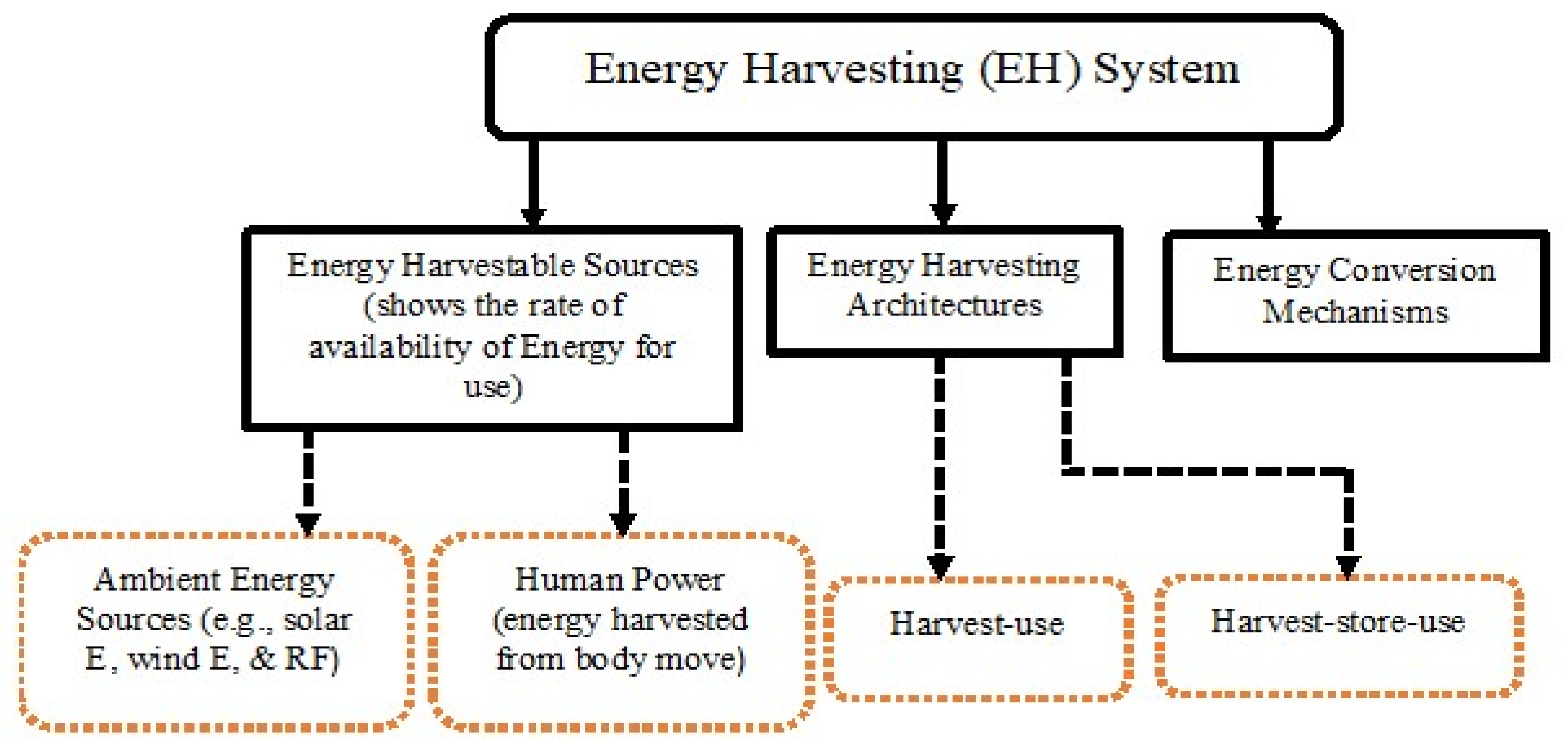
Energy scavenging (ES) refers to the conversion of energy from one form to another. Sensor nodes are powered by devices whose energies are derived from external sources in order to boost or prolong the network lifetime. Energy harvesting techniques have shown strong potentials to address the trade-offs between sensor-node lifetime and performance parameters, and to provide a lasting solution for the energy-hungry electronic devices [5]. The most popular technique of energy scavenging is the conversion of solar energy to electrical energy [3]. This type of energy harvestable source is greeted with several limitations that border around difficulty in controlling the intensity of direct sunlight with which may be affected by variations in weather conditions and seasonal patterns. For instance, the solar and wind sources of ES are limited by the durations and strengths attached to solar radiation or wind [5] which are subject to weather or seasonal constraints. Additionally, there may be inadequate sunlight at night to generate energy [6]. Other energy harvesting sources include thermal, mechanical vibrations, and RF energy. Among all, RF energy harvesting shows the most promising alternative to obtain energy for wireless devices even though it has the least power density [7]. This is because RF energy signals are pervasive whose systems have the potentials of harvesting sufficient energy to power many sensor devices. Hence, RF energy harvesters deliver more viable energy source for WSN and IoT-based applications. Figure 1 is a simplified block diagram of a typical energy scavenging system with three component parts: the energy source, the harvesting architecture, and the load.
- Energy Sources: This is usually characterized along the axes of controllable and non-controllable energy sources. A controllable energy source provides harvestable energy when he need arises whereas a non-controllable energy source is expected to harvest energy whenever available. Energy sources can be generally classified into two: ambient energy sources (relate to the energy sources from the environment such as solar energy, wind energy and RF energy) and human power (relate to energy sources as a result of the movement of body parts such as finger motion, walking, paddling) [3].
- Energy Harvesting (EH) Architectures: This can be divided into two—Harvest-Use and Harvest-Store-Use [3]. Harvest-Use depicts a timely scavenging of energy for use while Harvest-Store-Use harvests energy whenever it is available and stores the harvested energy for future use.
- Energy Conversion Mechanisms: This denotes the mechanisms for harvesting electrical energy from other energy sources. The selection of the type of energy conversion mechanism depends on the choice of energy source.
3.2. Rectifying Circuit
As discussed in [41,42], there are two key approaches to WPT—(a) the resonant coupling which includes inductive, and (b) the microwave power transfer (MPT). The use of rectenna as a rectifier is one common key technology for both types of WPTs. The components of the rectenna comprise: an antenna (for receiving microwave power), a low-pass filter (for preventing higher harmonics from reaching the rectifier), the rectifier with diodes and output filter (used to rectify the received microwave signal to DC). Indeed, the importance of the rectifying circuit technology to WPT cannot be overstressed as it finds application in the rectification of radio wave signals to DC conversion in all types of WPT architectures [42,43]. A theoretical approach based on inductive coupling has been provided in [41,42,43]. The beam efficiency is calculated by the Friis free space propagation model in Equation (12). The Friis transmission equation is applied at a far-field since Friis transmission model assumes a plane wave in the far-field while a spherical wave exists in the near-field where WPT is used [42]. Details of the application of Friis transmission model in calculating the received power are further discussed in Section 5 using Equation (12) with some graphical representation of the effect of distance on the received power by the sensing devices. It is noted in [42] that with simple resonant circuits using a resonant coupler (microwave filter) applied to WPT, a large amount of power (running into some kilowatts) can be transmitted without any radiation over mid-length distance at low frequencies (less than 10 MHz). Authors further showed that resonant coupling of WPT is more suitable for commercial applications. Other details on system specifications for the beam WPT, frequency bands for operation of non-beam WPT, regulation, beam efficiency, and WPT parameters are noted in [41,42,43].
3.3. Near-Field and Far-Field WPT Technologies
WPT technologies may be classified as near-field and far-field WPT [18,23,34]. A technique is near-field if the wavelength of the electromagnetic signal is longer than the transfer distance [23]. For example, if the resonant frequency is relatively low (less than 5 MHz) with a short transfer distance of about 5 cm. In this case, power is delivered to only close-by devices. Examples of near-field WPT include: (i) magnetic inductive coupling [12,15,16,18], (ii) magnetic resonant coupling [13,15,16,18], (iii) capacitive coupling [23], and (iv) magneto dynamic coupling [23]. By contrast, a technique is considered far-field if the wavelength of the electromagnetic signal is smaller than the transfer distance [16], and power is delivered to far-reaching or remotely located devices [23]. Examples include radio waves [18,19,23,44] and microwaves [19,23,44]. However, the use of far-field RF energy transfer is associated with path loss which consequently reduces the RF power on the rectifying antenna (rectenna). Visser [19] proposes a method to optimize the propagation channel and subsystems of the rectenna to improve the RF energy transport efficiency. In [45], authors presented the design, implementation and evaluation of In-N-Out scheme, a software-hardware solution for far-field WPT. Hinging on the potential drawbacks of the near-field system which include reduction of the coil size leading to a significant drop in the charging efficiency and low flexibility, the authors present a flexible far-field WPT system that does not require users to wear cumbersome charging devices and can also constantly charge medical implant residing in deep tissues of human body. Many discussions on the recent trends in WPT technology for energy harvesting, millimeter-wave/THz rectennas, MIMO-WPT, and advances in near-field WPT applications are noted in [41]. From the discussion on WPT techniques, inductive coupling WPT is considered the best approach, followed by WPT via radio waves [41]. In terms of commercialization, near-field WPT is well commercialized compared to far-field. For instance, in Europe and China, many public buses have used near-field wireless chargers with frequencies of 20kHz/85kHz and power from 60–200kW [41,42]. Additionally, 2017 marked the promotion of a cordless wireless charger for a mobile phone known as Qi standard in Apple Inc.
Table 2 shows the different modes of IoT energy harvesting for WPT technology while Table 3 shows the characteristics of wireless power transmission.
An exciting application of WPT as noted in [42,43] is the wireless charging of an electric vehicle. The various WPT technologies in Table 3 can be applied to charge electric vehicles. Discussions on regulation and safety issues reveal that inductive coupling WPT is considered the best approach, followed by WPT via radio waves [41]. However, wireless magnetic resonant power transfer has shown many advantages over other WPT methods due to its safety, lack of interference and efficiency at medium ranges [15,42]. The advantage of MPT charging is that it can be a multiuser and multipurpose system. Both power and information can be transmitted via the microwave connection [42].
4. Different Application Models of Wireless Power Transfer Technologies
This section discusses the different models of WPT technologies. In this section, we present some of the application scenarios of WPT technology. WPT has emerged with strong capability to address the energy problems of a WSN with potentials that can permanently provide energy-source solutions to future generation WSNs. WPT-based WSN is a network in which sensors are wirelessly energized through dedicated energy sources such as inductive coupling, magnetic resonance coupling, and RF-WPT technologies [5]. Here, the power transferred from the source to the target is not subject to weather or seasonal constraints compared to the traditional EH techniques.
4.1. Application with Static Wireless Charging Station (WCS): Mobile Nodes vs. Static WCS
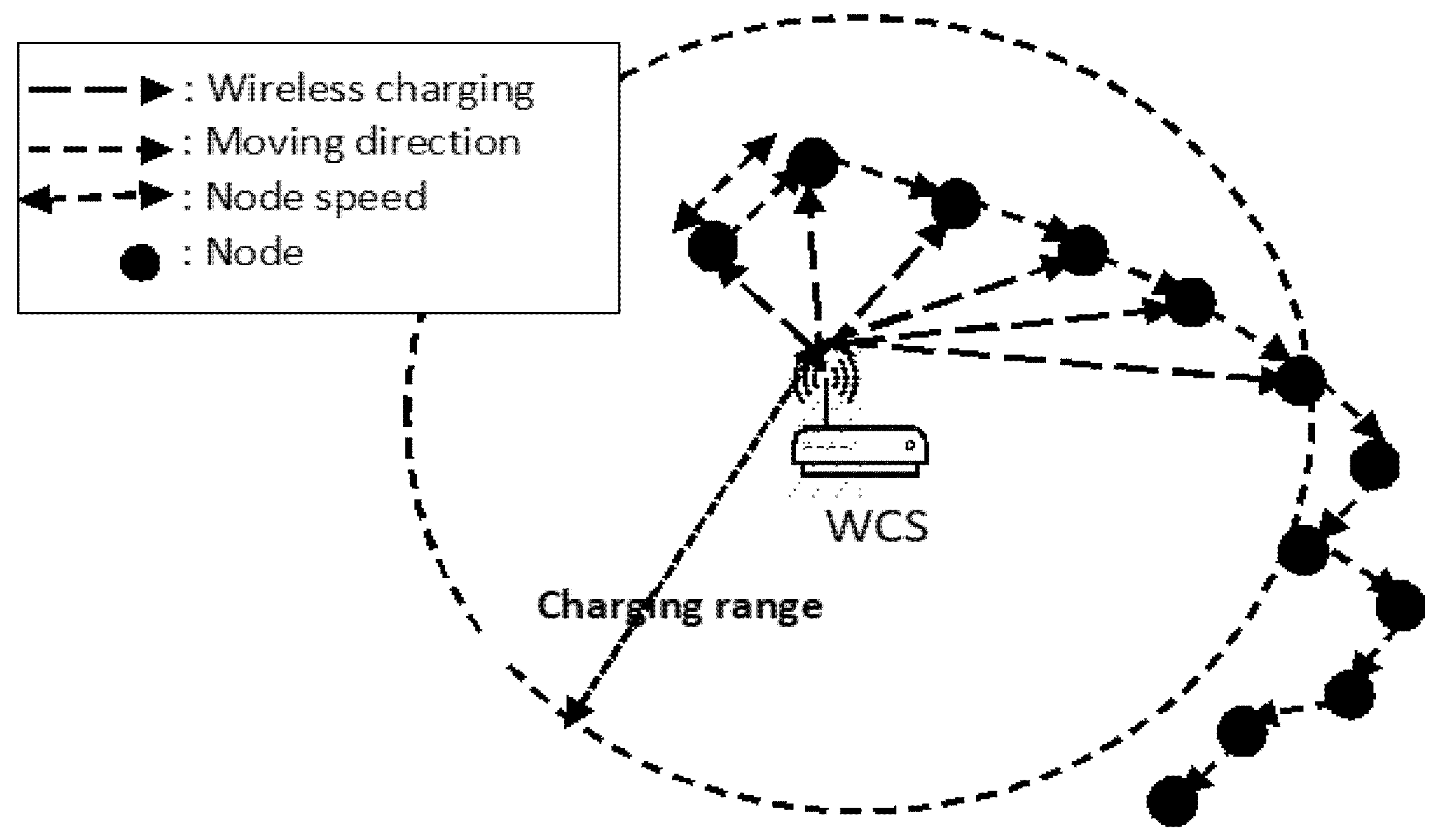
In this scenario, a WCS is deployed across a sensor network to wirelessly transfer power to IoT nodes within its coverage area or vicinity. The WCS transfers energy to the mobile nodes wirelessly as the nodes move within the coverage distance of the charger. This application model addresses the energy provisioning problem of the energy-hungry opportunistic IoT networks [12]. Because of the pervasive nature of wireless mobile devices, their energy-supply requirements over time have not been subdued with the use of plugs and wires, as the wired charging technologies cannot cope with them [12]. This brought into light the emergence of WPT which serves as a viable solution that enables battery-recharge without the use of plugs or wires. For the current scenario, an apparatus which performs this function is known as the WCS. Despite the obvious usefulness of using a WCS, this technique is limited in capability due to some limitations associated with WPT technology, which revolve around hardware capability [12], human security and safety considerations [12,25,27,28], thus limiting the use of WCS from radiating EM waves of higher power thereby further restricting the charging coverage of WCS. An alternative idea will be to install multiple copies of WCS to cover a larger percentage of the network area but this also comes with huge deployment costs. In essence, in spite of the limited charging coverage of WCS, energy is still supplied to the IoT nodes operating within the charging coverage. This is possible because of the random mobility-patterns of the sensor nodes. In [12], we see that the resultant energy received by a node depends on its mobility pattern and is largely determined by the node-speed as shown in Figure 2. For the present model, a slowly moving node that remains within the charging coverage of the WCS will continuously receive energy and this ceases as soon as it leaves the coverage area of WCS, thus leading to a form of irregular energy supply seen in many instances where some wireless devices are constantly charged while others are starved of energy supply. The energy-starvation period is likely to be short-lived as the node-speed increases, thus having a more regular pattern of energy provision. Figure 2 is an example of a sensor network with a static WCS and mobile nodes.
4.2. Application with a Mobile Wireless Charging Vehicle (WCV): Static Nodes vs. Mobile WCV
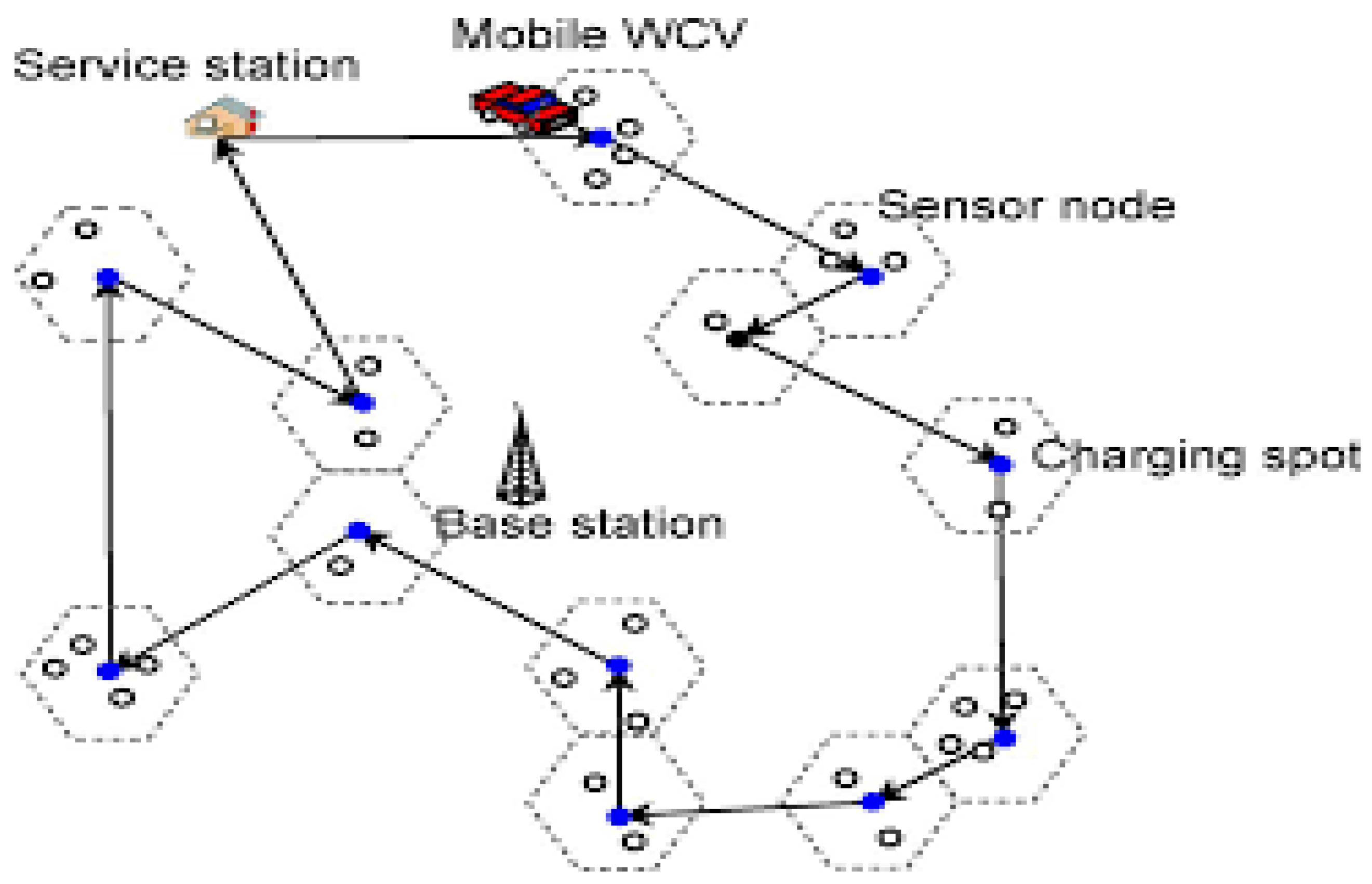
Unlike the first model, this case scenario shows a mobile WCV which periodically visits a sensor network with the sole aim of charging the batteries of the sensor nodes wirelessly. This is depicted in Figure 3. After the visit, the WCV returns to its service station for servicing which may be either recharging or battery replacement and prepares for another possible periodic visit.
4.3. Proposed Model: Mobile Data Collectors (Data Mules) Used as Wireless Mobile Battery Chargers (MBCs)/Power Transmitters
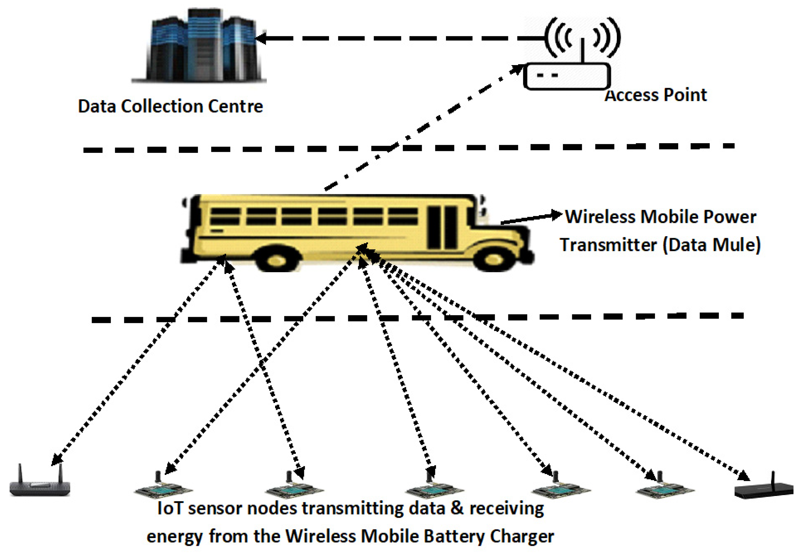
Figure 4 shows the architecture of a multi-node wireless mobile energy transmitter which opportunistically traverses the IoT sensor network to recharge the batteries of the sensors. The model shows a data mule which traverses the network for the purpose of data collection and energy transmission. Unlike the previous models, this model exploits the advantages inherent in vehicular networks for opportunistic data collection and power transmission to the sensor-nodes. In this scheme, we assume a uniform charging for all the sensor-nodes within the vicinity and coverage area of the wireless energy transmitter. Considering some trade-off factors, this model explores the energy provisioning process to the sensor-nodes based on their inter-meeting time with the energy transmitters. We shall be investigating the impact of inter-meeting time between the energy transmitters and the nodes on the efficiency of WPT based on different trade-offs. We will also consider the effect of increasing the sensor-nodes on the average energy charged by each sensor.
5. Problem Description, Formulation, and Solution
Since our proposed model intersects between both network lifetime and data collection efficiency, this section will be divided into two segments: (i) battery charging, and (ii) data collection. We are looking at a network with N number of sensor-nodes distributed across network area as shown in Figure 4. In order to recharge a sensor node’s battery, a wireless mobile battery charger (MBC) which is also used as a mobile data collector (MDC) opportunistically traverses the network for the purposes of data collection and battery charging. Since the movement is opportunistic, it is worth noting that the charger may be doing only charging when there is no data to collect from the sensor-nodes and vice versa. We will assume that the MBC takes off from a service station (S) with a traveling speed of V (m/s). On arrival at a sensor node , the MBC spends quantity of time to wirelessly recharge the battery of the node. Let represent the rate of transmitted energy of the MBC. Having charged the sensor-node , at the time of the MBC travels along its route to charge the next node. We will also assume that the MBC has enough energy to charge every sensor node in the network. A sensor node is assumed to have been fully charged when its battery capacity is and a minimum operational energy of is allowed. A network lifetime is threatened when the energy of the sensor node falls below the minimum operational energy .
The data collected by the MDC or data mule is transmitted to base station or access point (AP). A sensor node transmits its generated data to the MDC at a rate of (bits/s), so that . Each sensor node a certain amount of energy for data transmission. Here, we will adapt the energy consumption analysis for data mule model in [4,9]. We assume that the mobile battery charger (MBC) returns to the service to be serviced (maybe to replace or recharge its battery) before making another opportunistic movement to the network. Let denote the physical route traversed by the wireless mobile battery charger (MBC) over a trip cycle beginning from and ending at the service (S) station, and node covered by MBC along a predetermined route (R) is , for If denotes the distance between the MBC and the first sensor node visited along R and denote the distance between the and sensor nodes, denotes the time of arrival of the MBC at node , then we obtain:
Let denote the physical distance of route R and being the time spent by MBC to travel over a distance . Then, the renewable cycle time putting into consideration the vacation time of the battery charger is given as:
where is the total time spent by the wireless MBC across the entire network in order to wirelessly transfer power to the nodes. Next, we adapt the definitions and proofs in [4] to determine the renewable energy cycle. During this cycle, the amount of energy received by a node must equal the amount of energy it consumed. That is:
We note that at any opportunistic instance during a renewable cycle in which the MBC visits a node at a time , the node’s battery must not have to be recharged to Based on [4], we consider only energy cycles when a node gets fully recharged after being visited by the MBC. We note that the energy of a node is at ebb at a time . Hence, the second requirement in [4] is met as:
But and . Hence:
Some constraints may arise in several scenarios where for instance, (1) the charging rate of MBC is too small or the energy consumption rate of the sensor node is too large; and (2) the interval of time of visit of MBC to a node for battery recharging is too large. However, these are common physical parameters that tend to limit the MBC from achieving a lifetime renewable network for a WSN.
To determine the energy consumption for the data mule model when it collects data from the sensor nodes, we adapt the energy consumption analysis in [9]. Two cases are considered for the total energy consumption: (1) the energy consumption for data initiation (the data mule broadcasts the DREQ to the nodes and subsequently floods the network. This is denoted by the length of DREQ as and (2) the energy consumption for data collection (the nodes transmit their data to the mobile collector. The length of data collection is denoted by ). The energy consumptions for the duo have been derived in [9] and are given as:
where is the energy consumption for data initiation, N is the total number of IoT nodes in the network and is the energy consumption by a node for a transmission covering the neighborhood of r radius and is denoted by [9]:
where denotes the path attenuation factor, is the energy consumption of the transmitter, is the output of the antenna, and is the energy radiated irrespective of the range of transmission; is the energy consumption of a node for receiving, and r is the optimal node transmission radius given by:
Hence, the total energy consumption for all the nodes for data initiation is given by:
Similarly, the energy consumption for data transmission from the nodes to the mobile collector (data mule) depends on the number of nodes responding to the DREQ with available data to transmit in respect of the request from the data mule. Given a large number of nodes N (, the energy consumption for data collection as modeled in [9] is given by:
where is the average collection response rate of the node.
Then, the total energy consumption for all sensor-nodes for data collection is given by:
Total energy consumption for the network is the summation of the energy consumption for data initiation and data collection:
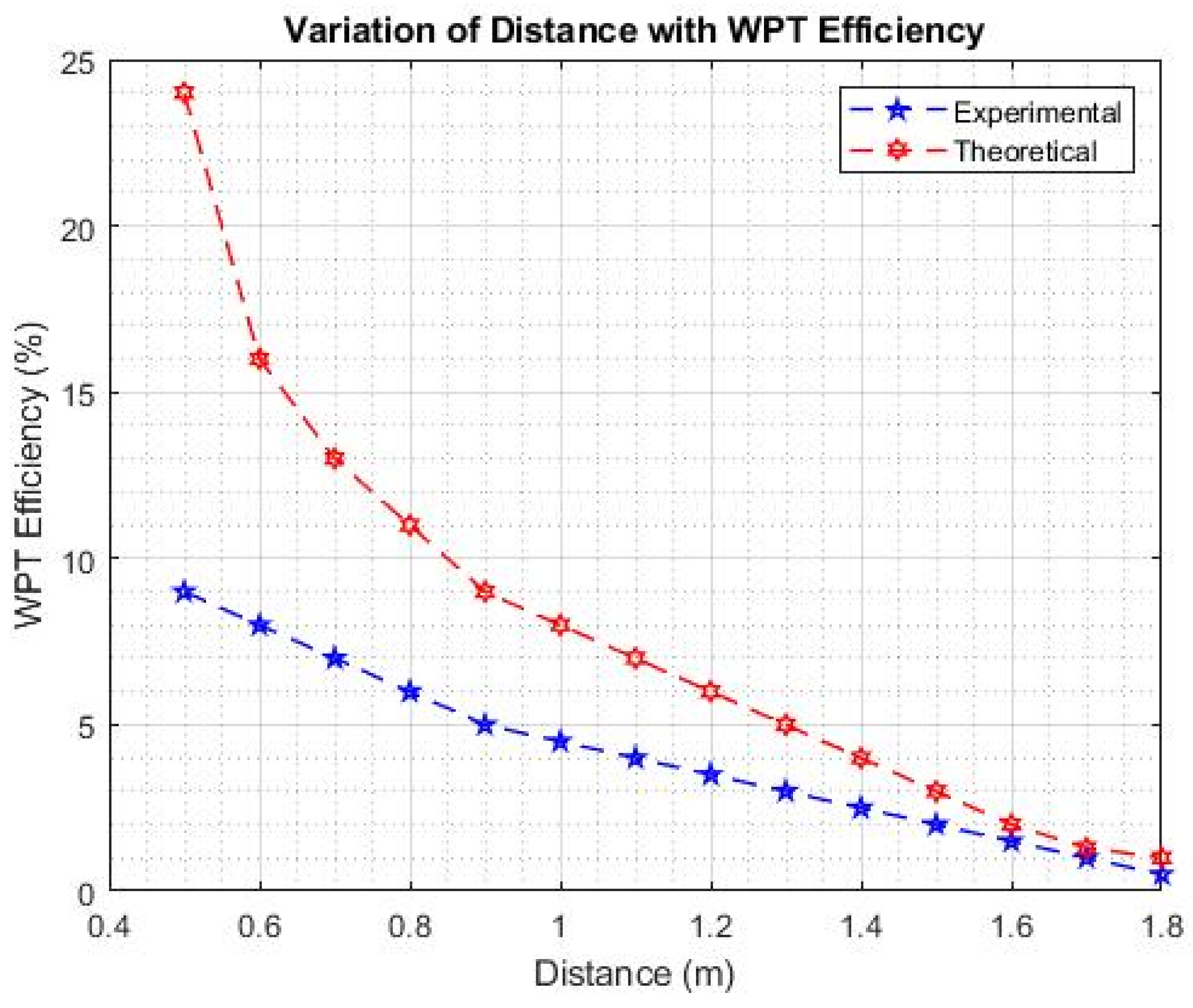
WPT Empirical Model: We adapt the empirical model for wireless power transfer in [5] to determine the effect of varying distances on the power transfer efficiency. Wireless mobile charging system performance is dependent on several factors including efficiency of the wireless power transfer, energy consumption of the sensor for data collection and transmission, feasible route locations, travelling time constraints, [5], etc. The empirical model in [5] is for wireless discharging and charging processes. As stated earlier, the efficiency of WPT depends on the transfer distance (as shown in Figure 5). However, we are not very much concerned with the distance. Our proposed model presupposes a uniform charging for all the sensor-nodes within the coverage area of the mobile MBC. This implies that each node receives a uniform charging as long as it is within the charging vicinity of the mobile charger. From [5], it is known that the relationship between transmit power, received power, and the wireless power transfer is usually associated with Friis’ free space propagation model given by:
where is the transmitted signal power of the MBC in Watts, is the received power by the sensor, S, in Watts, and are the gains of the antennas of the MBC and sensor S, respectively, d is the power transfer distance between the sensor and the MBC, and denotes the wavelength of signal power in meters [5]. Figure 5 shows the effect of varying the distance on the WPT efficiency.
The Friis free space propagation model in Equation (12) is obtained when the factor L known as system loss is equal to 1, implying no losses as shown in Equation (13). The free-space radio propagation model can be used to predict the received signal strength when the transmitter and the receiver have a clear LOS between them [46,47].
The parameter L is called system loss or other losses not associated with the propagation loss ( [46] and may include loss at the antenna, transmission line attenuation, los at various filters, etc. The factor L is usually greater than or equal to 1 with L = 1 for no such system losses. When L = 1, we then obtain Equation (12). The Friis free space propagation model is used to model the line-of-sight (LOS) path loss incurred in free space environment. It is valid only in the far-field region of the transmitted antenna [46,47,48] and is based on the inverse square law of distance which states that the received power at a particular distance from the transmitter decays by a factor of square of the distance as shown in Figure 5, which shows the variation of distance with WPT efficiency. Figure 5 is the graphical comparison of the theoretical and experimental model of WPT. From the graph, it is evident that the efficiency of a WPT largely depends on the distance between the sensor-nodes and the wireless MBCs.
6. Simulation Results and Analysis
The performance of our proposed model was evaluated by performing some additional experimental results using the RMASE simulator [49]. Two routing protocols were used for the simulations: (1) improved energy efficient ant-based routing (IEEABR) protocol and (2) the message-initiated constrained-based routing protocol. The full details for IEEABR and MCBR can be found in [50,51], respectively. MCBR is a proactive routing algorithm representing a recognized constraint-based flooding scheme, whereas IEEABR is a state-of-the-art routing protocol that utilizes the swarm-based ant behavior to give a low node-energy consumption. The node-energy consumption was modelled in accordance with the Waspmote-802.15.4 sensor-node using a transmission range of 35 m. Some of the simulation parameters used include a collection rate from 0.0 to 0.9 across 200 nodes, data rate is 250 kbps, data length is 512 bits, etc. Other parameters of the simulation are shown in Table 4.
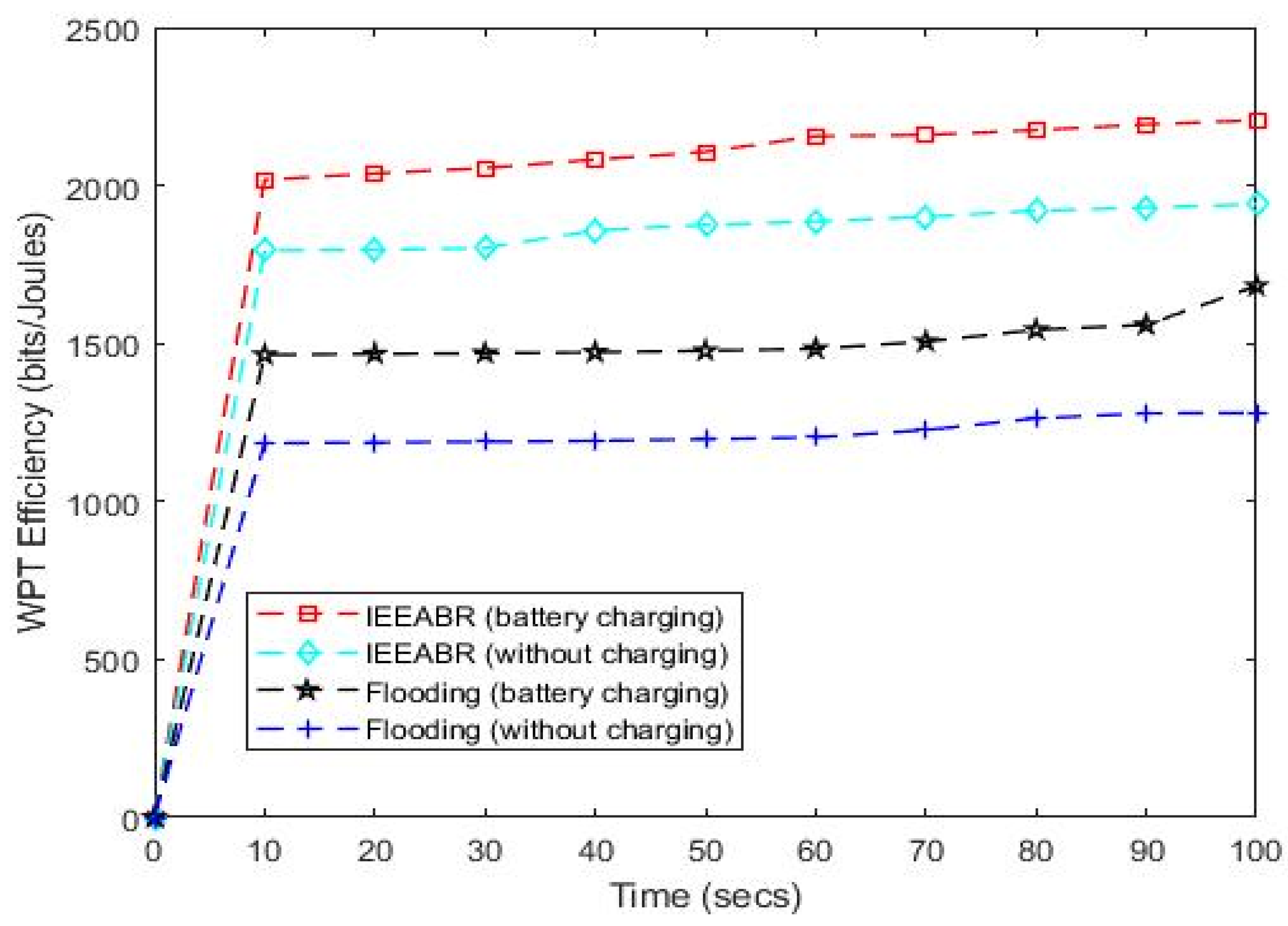
Figure 6 shows the impact of varying times of the wireless energy transmitters (power chargers) on the power transfer efficiency for MCBR-Flooding and IEEABR protocols respectively. As shown, IEEABR (being an ant-based protocol) performed better than MCBR-Flooding in terms of WPT efficiency. The figure shows that inter-meeting times (Tm) affect the energy provisioning to the sensor-nodes. The inter-meeting time (Tm) is defined here as the time-interval between a wireless mobile power charger (energy transmitter) and a sensor-node for data exchange or the time spent by a wireless MBC with a given IoT sensor-node in order to collect data and transmit energy to the node. Now, we will consider the different trade-offs (λ) for the energy provisioning process.
For λ = 1, Tm = High, the wireless energy transmitters are within the vicinity of the nodes and the inter-meeting time between the energy transmitters and the sensor-nodes is relatively high. This implies that the energy transmitters are moving at a minimal speed within the coverage area. Thus, at a constant distance (same vicinity of the nodes) and reduced speed, time is increased and the nodes can receive enough energy to be able to charge their batteries. This is designated as “battery charging” in Figure 6 because the sensor-nodes are able to charge their batteries at a high inter-meeting time with the power chargers. We assume a uniform charging for all the sensor-nodes provided that the wireless energy transmitters are within the vicinity of the nodes. Hence, increasing the inter-meeting time between the wireless energy transmitters and the sensor-nodes increases the WPT efficiency as shown in Figure 6. This also justifies the graph of Figure 5 obtained through empirical model which shows WPT efficiency increasing inversely proportionally with the distance (i.e., WPT efficiency increased as distance reduced and vice versa). This shows that wireless mobile power chargers within the vicinity of the sensor-nodes and moving at a minimum speed have high WPT efficiency.
For λ = 0, Tm = Low, the wireless energy transmitters are outside the coverage of the nodes and the inter-meeting time between the senor-nodes and the energy transmitters is very small. This is known as the energy starving moment of the sensor-nodes because only minimum energy is transmitted to the nodes within this shortest time. This may be because the mobile power chargers have not yet arrived within the vicinity of the nodes or that they are moving at a high speed within the coverage area. At high speeds, inter-meeting times are reduced and only minimum energy can be transmitted to the nodes and nodes will be power-hungry. Hence, WPT efficiency is reduced as the sensor-nodes are unable to efficiently charge their batteries. This is designated as “without charging” in Figure 6.
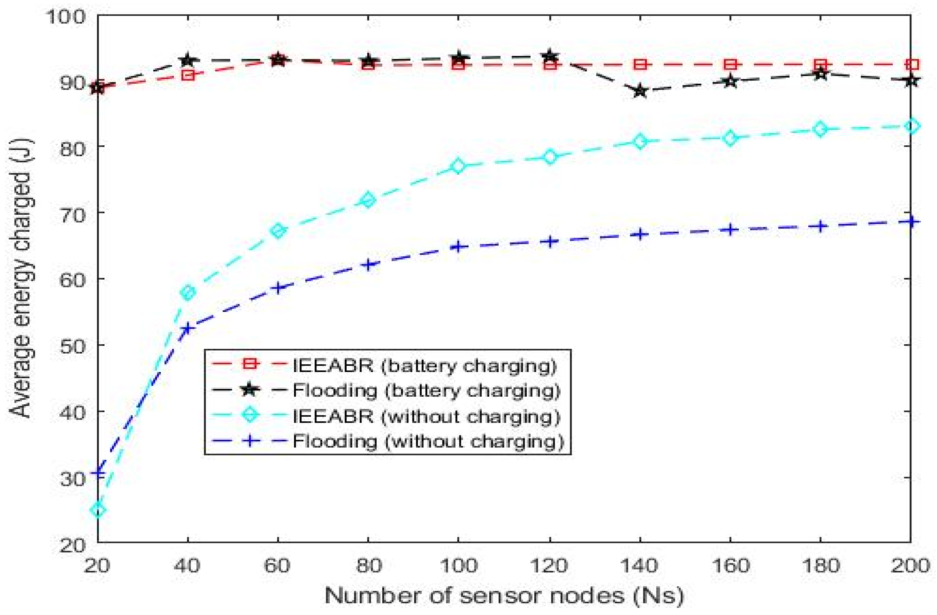
Figure 7 shows the effect of varying the number of sensor-nodes on the average energy charged for MCBR-Flooding and IEEABR protocols by considering different trade-offs (λ). Again, IEEABR (an ant-based protocol) outperformed MCBR-Flooding protocol. Here, a given number of IoT sensor-nodes (Ns = 200), sparsely distributed across the network, was varied in accordance with the energy received from the mobile power chargers. And it is observed that the energy charged by the sensor-nodes initially increased proportionally with the number of sensor-nodes in the network and then stabilized. Let us consider the different trade-off factors. For λ = 0, the energy transmitters are not optimally placed within the vicinity and coverage area of the sensor-nodes and only little or no energy is transmitted to the sensor-nodes. Hence, sensor-nodes receive minimum or no energy to charge their batteries because the energy transmitted is not fairly and uniformly distributed across the network. The sensor-nodes are assumed not to be charging at maximum level and this is therefore designated as “without charging” as shown in Figure 7. However, the total energy charged is observed to increase with the number of sensor nodes in the network. For λ = 1, the mobile battery chargers (energy transmitters) are optimally placed within the vicinity of the sensor-nodes and the energy transmitted in the network is maximized. Here, energy is fairly and uniformly distributed across the network as long as the energy transmitters are within the coverage area. As shown in Figure 7, the energy transmitted (i.e., average energy charged) initially increased proportionally with the number of sensor-nodes and then stabilized. This is designated as “battery charging” in the diagram. From the graph, we can see that when Ns > 80 (for IEEABR) and Ns > 140 (for MCBR-Flooding), the change in the total energy received (average energy charged by the sensors) is insignificant. This may be connected with the fact that each sensor-node in the vicinity or coverage area receives a uniform charging from the power chargers (wireless energy transmitters).
7. Conclusions
Data collection and transmission operations are often marred due to the limited lifetime of the energy-constrained sensor-nodes in an IoT network. A battery-powered sensor-node has the huge limitation of finite node-lifetime. This is a fundamental bottleneck that limits the WSN’s operational performance and efficiency. In this paper, we considered a recent breakthrough in the application of WPT technologies and provided a comprehensive review of WPT technologies that are applicable for IoT-SC application-scenarios. We presented the different application models of WPT and closely re-examined each model with a view to determining the most energy-efficient and cost-effective technique. We proposed a model that combines both data collection and wireless energy transfer schemes and also investigated the WPT efficiency of a power-hungry opportunistic IoT sensor network whereby mobile collectors (data mules) are opportunistically exploited as wireless energy transmitters, which traverse the network and recharge the energy-constrained IoT sensor-nodes placed within their charging vicinity or coverage area. We conducted an empirical study of WPT model to determine the effect of varying the distance on the power transfer efficiency.
Given the different trade-off factors, the energy provisioning of the sensor-nodes follows the inter-meeting time between the energy transmitters and the IoT-nodes. Essentially, a slow-moving wireless energy transmitter within the charging vicinity of the node transmits more energy than a fast-moving energy transmitter within the same coverage area. The former has a higher power transfer efficiency than the latter. This finding gives some useful insight into the design of energy-efficient opportunistic IoT sensor networks. The proposed model combines both data collection and wireless energy transfer techniques. The scheme is focused on exploiting the recent breakthrough in WPT technology and the advantages offered by opportunistic networks. This is the first of such schemes that leverage on the advantages inherent in the separate schemes for an energy efficient opportunistic IoT network. After a careful study of the problem description and formulation, we provided some simulation analysis to further backup our proposed technique. The simulation results further justified the result obtained through empirical model. From the results, we showed that a network system operating under our proposed scheme can indeed remain perpetually operational. The results of the simulation also give some useful insights into future research directions.
Author Contributions
Conceptualization, G.K.I.; Data curation, K.L.-M.A.; Investigation, J.K.P.S.; Software, G.K.I.; Validation, G.K.I.; Formal analysis, G.K.I.; Visualization, K.L.-M.A.; Supervision, K.L.-M.A. and J.K.P.S.; Writing—original draft preparation, G.K.I.; Writing—review and editing, K.L.-M.A. and J.K.P.S. All authors have read and agreed to the published version of the manuscript.
Funding
This research received no external funding.
Data Availability Statement
Not applicable.
Conflicts of Interest
The authors declare no conflict of interest.
References
- Kumar, A.; Singh, D. Importance of Energy in Wireless Sensor Networks: A Survey. Int. J. Eng. Sci. 2016, 17, 500–505. [Google Scholar]
- Zhong, S.; Wang, X. Energy allocation and utilization for wirelessly powered IoT networks. IEEE Internet Things J. 2018, 5, 2781–2792. [Google Scholar] [CrossRef]
- Sudevalayam, S.; Kulkarni, P. Energy harvesting sensor nodes: Survey and implications. IEEE Commun. Surv. Tutor. 2010, 13, 443–461. [Google Scholar] [CrossRef] [Green Version]
- Xie, L.; Shi, Y.; Hou, Y.T.; Sherali, H.D. Making sensor networks immortal: An energy-renewal approach with wireless power transfer. IEEE/ACM Trans. Netw. 2012, 20, 1748–1761. [Google Scholar] [CrossRef]
- Sangare, F.; Xiao, Y.; Niyato, D.; Han, Z. Mobile charging in wireless-powered sensor networks: Optimal scheduling and experimental implementation. IEEE Trans. Veh. Technol. 2017, 66, 7400–7410. [Google Scholar] [CrossRef]
- Tran, H.V.; Kaddoum, G. RF wireless power transfer: Regreening future networks. IEEE Potentials 2018, 37, 35–41. [Google Scholar] [CrossRef] [Green Version]
- Cansiz, M.; Altinel, D.; Kurt, G.K. Efficiency in RF energy harvesting systems: A comprehensive review. Energy 2019, 174, 292–309. [Google Scholar] [CrossRef]
- Niyato, D.; Wang, P.; Kim, D.I.; Han, Z. Opportunistic energy scheduling in wireless powered sensor networks. In Proceedings of the 2016 IEEE 84th Vehicular Technology Conference (VTC-Fall), Montreal, QC, Canada, 18–21 September 2016; IEEE: Piscataway, NJ, USA, 2016; pp. 1–6. [Google Scholar]
- Ang, K.L.M.; Seng, J.K.P.; Zungeru, A.M. Optimizing energy consumption for big data collection in large-scale wireless sensor networks with mobile collectors. IEEE Syst. J. 2017, 12, 616–626. [Google Scholar] [CrossRef]
- Teng, H.; Liu, Y.; Liu, A.; Xiong, N.N.; Cai, Z.; Wang, T.; Liu, X. A novel code data dissemination scheme for Internet of Things through mobile vehicle of smart cities. Future Gener. Comput. Syst. 2019, 94, 351–367. [Google Scholar] [CrossRef]
- Anastasi, G.; Conti, M.; Di Francesco, M. Data collection in sensor networks with data mules: An integrated simulation analysis. In Proceedings of the 2008 IEEE Symposium on Computers and Communications, Marrakech, Morocco, 6–9 July 2008; IEEE: Piscataway, NJ, USA, 2008; pp. 1096–1102. [Google Scholar]
- Ko, S.W.; Kim, S.L. Impact of Node Speed on Energy-Constrained Opportunistic Internet-of-Things with Wireless Power Transfer. Sensors 2018, 18, 2398. [Google Scholar] [CrossRef] [PubMed] [Green Version]
- Kurs, A.; Karalis, A.; Moffatt, R.; Joannopoulos, J.D.; Fisher, P.; Soljačić, M. Wireless power transfer via strongly coupled magnetic resonances. Science 2007, 317, 83–86. [Google Scholar] [CrossRef] [Green Version]
- Huang, K.; Lau, V.K. Enabling wireless power transfer in cellular networks: Architecture, modeling and deployment. IEEE Trans. Wirel. Commun. 2014, 13, 902–912. [Google Scholar] [CrossRef] [Green Version]
- Griffin, B.; Detweiler, C. Resonant wireless power transfer to ground sensors from a UAV. In Proceedings of the 2012 IEEE International Conference on Robotics and Automation, Saint Paul, MN, USA, 14–18 May 2012; IEEE: Piscataway, NJ, USA, 2012; pp. 2660–2665. [Google Scholar]
- Barman, S.D.; Reza, A.W.; Kumar, N.; Karim, M.E.; Munir, A.B. Wireless powering by magnetic resonant coupling: Recent trends in wireless power transfer system and its applications. Renew. Sustain. Energy Rev. 2015, 51, 1525–1552. [Google Scholar] [CrossRef]
- Kesler, M. Highly Resonant Wireless Power Transfer: Safe, Efficient, and over Distance; Witricity Corporation: Watertown, MA, USA, 2013; pp. 1–32. [Google Scholar]
- Setiawan, D.; Aziz, A.A.; Kim, D.I.; Choi, K.W. Experiment, modeling, and analysis of wireless-powered sensor network for energy neutral power management. IEEE Syst. J. 2017, 12, 3381–3392. [Google Scholar] [CrossRef] [Green Version]
- Visser, H.J. Indoor wireless RF energy transfer for powering wireless sensors. Radioengineering 2012, 21, 963–973. [Google Scholar]
- Farinholt, K.M.; Park, G.; Farrar, C.R. RF energy transmission for a low-power wireless impedance sensor node. IEEE Sens. J. 2009, 9, 793–800. [Google Scholar] [CrossRef]
- Ang, L.M.; Seng, K.P.; Ijemaru, G.K.; Zungeru, A.M. Deployment of IoV for smart cities: Applications, architecture, and challenges. IEEE Access 2018, 7, 6473–6492. [Google Scholar] [CrossRef]
- Shah, R.C.; Roy, S.; Jain, S.; Brunette, W. Data mules: Modeling and analysis of a three-tier architecture for sparse sensor networks. Ad Hoc Netw. 2003, 1, 215–233. [Google Scholar] [CrossRef]
- Jawad, A.M.; Nordin, R.; Gharghan, S.K.; Jawad, H.M.; Ismail, M. Opportunities and challenges for near-field wireless power transfer: A review. Energies 2017, 10, 1022. [Google Scholar] [CrossRef]
- Molefi, M.; Markus, E.D.; Abu-Mahfouz, A. Wireless Power Transfer for IoT Devices-A Review. In Proceedings of the 2019 International Multidisciplinary Information Technology and Engineering Conference (IMITEC), Vanderbijlpark, South Africa, 21–22 November 2019; IEEE: Piscataway, NJ, USA, 2019; pp. 1–8. [Google Scholar]
- Liu, Q.; Yildirim, K.S.; Pawełczak, P.; Warnier, M. Safe and secure wireless power transfer networks: Challenges and opportunities in RF-based systems. IEEE Commun. Mag. 2016, 54, 74–79. [Google Scholar] [CrossRef]
- Collado, A.; Daskalakis, S.N.; Niotaki, K.; Martinez, R.; Bolos, F.; Georgiadis, A. Rectifier design challenges for RF wireless power transfer and energy harvesting systems. Radioengineering 2017, 26, 411–417. [Google Scholar] [CrossRef]
- Dai, R.; Zhao, Y.; Chen, G.; Dou, W.; Tian, C.; Wu, X.; He, T. Robustly safe charging for wireless power transfer. In Proceedings of the IEEE INFOCOM 2018–IEEE Conference on Computer Communications, Honolulu, HI, USA, 16–19 April 2018; IEEE: Piscataway, NJ, USA, 2018; pp. 378–386. [Google Scholar]
- Dai, H.; Liu, Y.; Chen, G.; Wu, X.; He, T.; Liu, A.X.; Ma, H. Safe charging for wireless power transfer. IEEE/ACM Trans. Netw. 2017, 25, 3531–3544. [Google Scholar] [CrossRef]
- Li, L.; Dai, H.; Chen, G.; Zheng, J.; Dou, W.; Wu, X. Radiation constrained fair charging for wireless power transfer. ACM Trans. Sens. Netw. 2019, 15, 1–33. [Google Scholar] [CrossRef]
- Tran, H.V.; Kaddoum, G. Green cell-less design for RF-wireless power transfer networks. In Proceedings of the 2018 IEEE Wireless Communications and Networking Conference (WCNC), Barcelona, Spain, 15–18 April 2018; IEEE: Piscataway, NJ, USA, 2018; pp. 1–6. [Google Scholar]
- Rajaram, A.; Jayakody, D.N.K.; Srinivasan, K.; Chen, B.; Sharma, V. Opportunistic-Harvesting: RF wireless power transfer scheme for multiple access relays system. IEEE Access 2017, 5, 16084–16099. [Google Scholar] [CrossRef]
- Ejaz, W.; Naeem, M.; Basharat, M.; Anpalagan, A.; Kandeepan, S. Efficient wireless power transfer in software-defined wireless sensor networks. IEEE Sens. J. 2016, 16, 7409–7420. [Google Scholar] [CrossRef]
- Li, K.; Ni, W.; Duan, L.; Abolhasan, M.; Niu, J. Wireless power transfer and data collection in wireless sensor networks. IEEE Trans. Veh. Technol. 2017, 67, 2686–2697. [Google Scholar] [CrossRef] [Green Version]
- Li, K.; Ni, W.; Tovar, E.; Jamalipour, A. On-board deep Q-network for UAV-assisted online power transfer and data collection. IEEE Trans. Veh. Technol. 2019, 68, 12215–12226. [Google Scholar] [CrossRef]
- Wang, H.; Ding, G.; Gao, F.; Chen, J.; Wang, J.; Wang, L. Power control in UAV-supported ultra-dense networks: Communications, caching, and energy transfer. IEEE Commun. Mag. 2018, 56, 28–34. [Google Scholar] [CrossRef] [Green Version]
- Zeng, Y.; Zhang, R.; Lim, T.J. Wireless communications with unmanned aerial vehicles: Opportunities and challenges. IEEE Commun. Mag. 2016, 54, 36–42. [Google Scholar] [CrossRef] [Green Version]
- Radanliev, P.; De Roure, D.; Walton, R.; Van Kleek, M.; Montalvo, R.M.; Santos, O.; Anthi, E. Artificial intelligence and machine learning in dynamic cyber risk analytics at the edge. SN Appl. Sci. 2020, 2, 1–8. [Google Scholar] [CrossRef]
- Zhu, Q.; Rieger, C.; Başar, T. A hierarchical security architecture for cyber-physical systems. In Proceedings of the 2011 4th International Symposium on Resilient Control Systems, Boise, ID, USA, 9–11 August 2011; IEEE: Piscataway, NJ, USA, 2011; pp. 15–20. [Google Scholar]
- Leitão, P.; Colombo, A.W.; Karnouskos, S. Industrial automation based on cyber-physical systems technologies: Prototype implementations and challenges. Comput. Ind. 2016, 81, 11–25. [Google Scholar] [CrossRef] [Green Version]
- Wu, Y.; Li, Z.; Van Nostrand, N.; Liu, J. Security and privacy in the age of cordless power world. In Proceedings of the 18th Conference on Embedded Networked Sensor Systems, Virtual Event, Japan, 16–19 November 2020; pp. 717–718. [Google Scholar]
- Shinohara, N. Trends in Wireless Power Transfer: WPT Technology for Energy Harvesting, Mllimeter-Wave/THz Rectennas, MIMO-WPT, and Advances in Near-Field WPT Applications. IEEE Microw. Mag. 2020, 22, 46–59. [Google Scholar] [CrossRef]
- Shinohara, N. Power without wires. IEEE Microw. Mag. 2011, 12, S64–S73. [Google Scholar] [CrossRef]
- Shinohara, N. Wireless power transfer in Japan: Regulations and activities. In Proceedings of the 2020 14th European Conference on Antennas and Propagation (EuCAP), Copenhagen, Denmark, 15–20 March 2020; IEEE: Piscataway, NJ, USA, 2020; pp. 1–4. [Google Scholar]
- Naoki, S. Wireless Power Transfer: Theory, Technology, and Applications; Institute of Engineering Technology: London, UK, 2018; ISBN 978-178561-346-3. [Google Scholar]
- Fan, X.; Shangguan, L.; Howard, R.; Zhang, Y.; Peng, Y.; Xiong, J.; Li, X.Y. Towards flexible wireless charging for medical implants using distributed antenna system. In Proceedings of the 26th Annual International Conference on Mobile Computing and Networking, London, UK, 21–25 September 2020; pp. 1–15. [Google Scholar]
- Yoon, S.U.; Cheng, L.; Ghazanfari, E.; Pamukcu, S.; Suleiman, M.T. A radio propagation model for wireless underground sensor networks. In Proceedings of the 2011 IEEE Global Telecommunications Conference-GLOBECOM 2011, Houston, TX, USA, 5–9 December 2011; IEEE: Piscataway, NJ, USA, 2011; pp. 1–5. [Google Scholar]
- Saadat, S. Mobility and propagation models in multi-hop cognitive radio networks. In Proceedings of the 2013 IEEE Int. Conference on Space Science and Communication (IconSpace), Melaka, Malaysia, 1–3 July 2013; IEEE: Piscataway, NJ, USA, 2013; pp. 375–379. [Google Scholar]
- De Moraes, R.M.; de Almeida, I.P.; Menezes, L.R. A Radio Propagation Model for Dense Wireless Networks. Int. J. Wirel. Inf. Netw. 2019, 26, 90–95. [Google Scholar] [CrossRef]
- Zhang, Y.; Simon, G.; Balogh, G. High-level sensor network simulations for routing performance evaluations. In Proceedings of the 3rd International Conference on Networked Sensing Systems (INSS06); Association for Computing Machinery: New York, NY, USA, 2006. [Google Scholar]
- Ketshabetswe, L.K.; Zungeru, A.M.; Mangwala, M.; Chuma, J.M.; Sigweni, B. Communication protocols for wireless sensor networks: A survey and comparison. Heliyon 2019, 5, e01591. [Google Scholar] [CrossRef] [PubMed] [Green Version]
- Zhang, Y.; Fromherz, M. Message-initiated constraint-based routing for wireless ad-hoc sensor networks. In Proceedings of the First IEEE Consumer Communications and Networking Conference, CCNC 2004, Las Vegas, NV, USA, 5–8 January 2004; IEEE: Piscataway, NJ, USA, 2004; pp. 648–650. [Google Scholar]
Figure 1.
Block diagram of an EH System.

Figure 2.
Wireless Charging Station (WCS) with Mobile Nodes. A node continuously receives energy once it is within the charging coverage of the WCS.
Figure 2.
Wireless Charging Station (WCS) with Mobile Nodes. A node continuously receives energy once it is within the charging coverage of the WCS.

Figure 3.
A model of wireless charging vehicle which periodically visits a WSN to recharge the batteries of sensors.
Figure 3.
A model of wireless charging vehicle which periodically visits a WSN to recharge the batteries of sensors.

Figure 4.
Architecture of a multi-node wireless mobile battery charger (MBC) which doubles as mobile data collector and wireless energy transmitter. The MBC opportunistically traverses the IoT network to collect data and recharge the batteries of the sensor-nodes.
Figure 4.
Architecture of a multi-node wireless mobile battery charger (MBC) which doubles as mobile data collector and wireless energy transmitter. The MBC opportunistically traverses the IoT network to collect data and recharge the batteries of the sensor-nodes.

Figure 5.
Effect of varying distances on WPT efficiency.

Figure 6.
WPT efficiency at varying times of the wireless mobile battery charger (MBC) for MCBR-Flooding and IEEABR protocols.
Figure 6.
WPT efficiency at varying times of the wireless mobile battery charger (MBC) for MCBR-Flooding and IEEABR protocols.

Figure 7.
Effect of number of sensor-nodes on average energy charged for MCBR-Flooding and IEEABR routing protocols.
Figure 7.
Effect of number of sensor-nodes on average energy charged for MCBR-Flooding and IEEABR routing protocols.

Table 2.
Different modes of IoT energy harvesting for WPT technology.
| Ref | Year | IoT Energy Harvesting Mode | Characteristics of the Paper |
|---|---|---|---|
| [2] | 2018 | RF-based WPT | The paper considered a wireless RF powered IoT system with a central node and multiple RF powered sensors acting as both power receivers and data transmitters |
| [12] | 2018 | EM radiation | The paper revealed a case of device-to-device (D2D) communication seen in the data exchange between the nodes and the WCS |
| [18] | 2017 | RF-based WPT | The paper provided a high-level abstract system model of WPSN based on real-life experiments. |
| [25] | 2016 | RF-based WPT | The study provided the vulnerabilities associated with WPT networks |
| [23] | 2017 | EM wave energy | The study provided a concise review on some recent advancements specific to near-field WPT techniques |
| [6,30] | 2018 | RF-based WPT | The study provided health and safety requirements necessary for the permissible exposure level to EM radiation as well as the charging performance |
Table 3.
Characteristics of wireless power transmission.
| Ref. | Wireless Power Transfer Techniques | ||
|---|---|---|---|
| [15,23,41,42,43] | WPT via Radio Waves | Resonant Coupling | Inductive Coupling |
| Field | Electromagnetic (EM) | Electric (E), Magnetic (H), or EM | Magnetic (H) |
| Method | Antenna | Resonator | Coil |
| Efficiency | Low to High | High | High |
| Distance | Short to long | Medium | Short |
| Power | Low to high | High | High |
| Safety | EM | None (Evanescent) | Magnetic |
| Regulation | Radio wave | Under discussion | Under discussion |
| Applications | Electric vehicles | Electric vehicles, mobile phones | EVs, mobile phones |
| Frequency | - | 5.92–12.5 MHz | 125–150 kHz |
| Output Power (W) | - | 4.2 | Up to 5 |
| Efficiency (%) | - | 40–60 | 70–90 |
Table 4.
Simulation parameters.
| Parameters | Values |
|---|---|
| Routing Protocols | MCBR_Flooding, IEEABR |
| X_dist, Y_dist, X-offset, Y-offset, X-density, Y-density, X-shift, Y-shift | 1, 1, 0.1, 0.1, 1, 1, 0.2, 0.2 |
| Node distribution | Random distribution |
| Source type, Destination type | Static, Mobile |
| Center type, radius, Destination rate | Random, 1, 0.5, 0 |
| Maximum number of retransmissions (n) | 3 |
| Strength, Initial power, Random power, Cycle time, Active period, Init active cycles | 1, 1000, 0, 10 10, 0.1, 0 |
| Propagation model | Two-ray ground reflection |
| Data traffic | Constant bit rate (CBR) |
| Data rate | 250 kbps |
| Simulation time, Average simulation time Number of nodes (N) | 360 s, 10 200 |
| Energy consumption | Wasp mote-802.15.4 |
| Propagation model | Probabilistic |
| Time of topology change | 2 s |
Publisher’s Note: MDPI stays neutral with regard to jurisdictional claims in published maps and institutional affiliations. |
© 2021 by the authors. Licensee MDPI, Basel, Switzerland. This article is an open access article distributed under the terms and conditions of the Creative Commons Attribution (CC BY) license (http://creativecommons.org/licenses/by/4.0/).
Share and Cite
MDPI and ACS Style
Ijemaru, G.K.; Ang, K.L.-M.; Seng, J.K.P. Mobile Collectors for Opportunistic Internet of Things in Smart City Environment with Wireless Power Transfer. Electronics 2021, 10, 697. https://doi.org/10.3390/electronics10060697
AMA Style
Ijemaru GK, Ang KL-M, Seng JKP. Mobile Collectors for Opportunistic Internet of Things in Smart City Environment with Wireless Power Transfer. Electronics. 2021; 10(6):697. https://doi.org/10.3390/electronics10060697
Chicago/Turabian StyleIjemaru, Gerald K., Kenneth L.-M. Ang, and Jasmine K. P. Seng. 2021. "Mobile Collectors for Opportunistic Internet of Things in Smart City Environment with Wireless Power Transfer" Electronics 10, no. 6: 697. https://doi.org/10.3390/electronics10060697
Note that from the first issue of 2016, this journal uses article numbers instead of page numbers. See further details here.