
Coordinated Control of Voltage Balancers for the Regulation of Unbalanced Voltage in a Multi-Node Bipolar DC Distribution Network


College of Electrical Engineering, Sichuan University, Chengdu 610065, China
*
Author to whom correspondence should be addressed.
Electronics 2022, 11(1), 166; https://doi.org/10.3390/electronics11010166
Submission received: 6 November 2021
/
Revised: 27 December 2021
/
Accepted: 3 January 2022
/
Published: 5 January 2022
(This article belongs to the Special Issue Power Electronics Contribution to Renewable Energy Conversion: Progress and Challenges)
Abstract
:In a bipolar DC distribution network, the unbalanced load resistance, line resistance and renewable energy source will cause an unbalanced current for each node of the neutral line and lead to its unbalanced voltage. This is a unique power quality problem of bipolar DC distribution networks, which will increase the power loss in the network and lead to overcurrent protection of the neutral line in serious cases. A voltage balancer can be adopted to suppress the unbalanced voltage and current. However, the existing literature does not consider the consistent application of multiple voltage balancers in a multi-node bipolar DC distribution network. This paper creatively proposes a consensus control topology combining primary control and secondary control in a radial multi-node bipolar DC distribution network with voltage balancers. In this paper, the formulas for the positive and negative current and duty cycle of a bipolar DC distribution network with voltage balancers are derived, and improved voltage balancer modeling based on a consensus algorithm is built. The radial multi-node bipolar DC distribution network is established in MATLAB/Simulink. The simulation results compare the consensus control with the traditional droop control and verify the effectiveness of the new control structure with voltage balancers.
1. Introduction
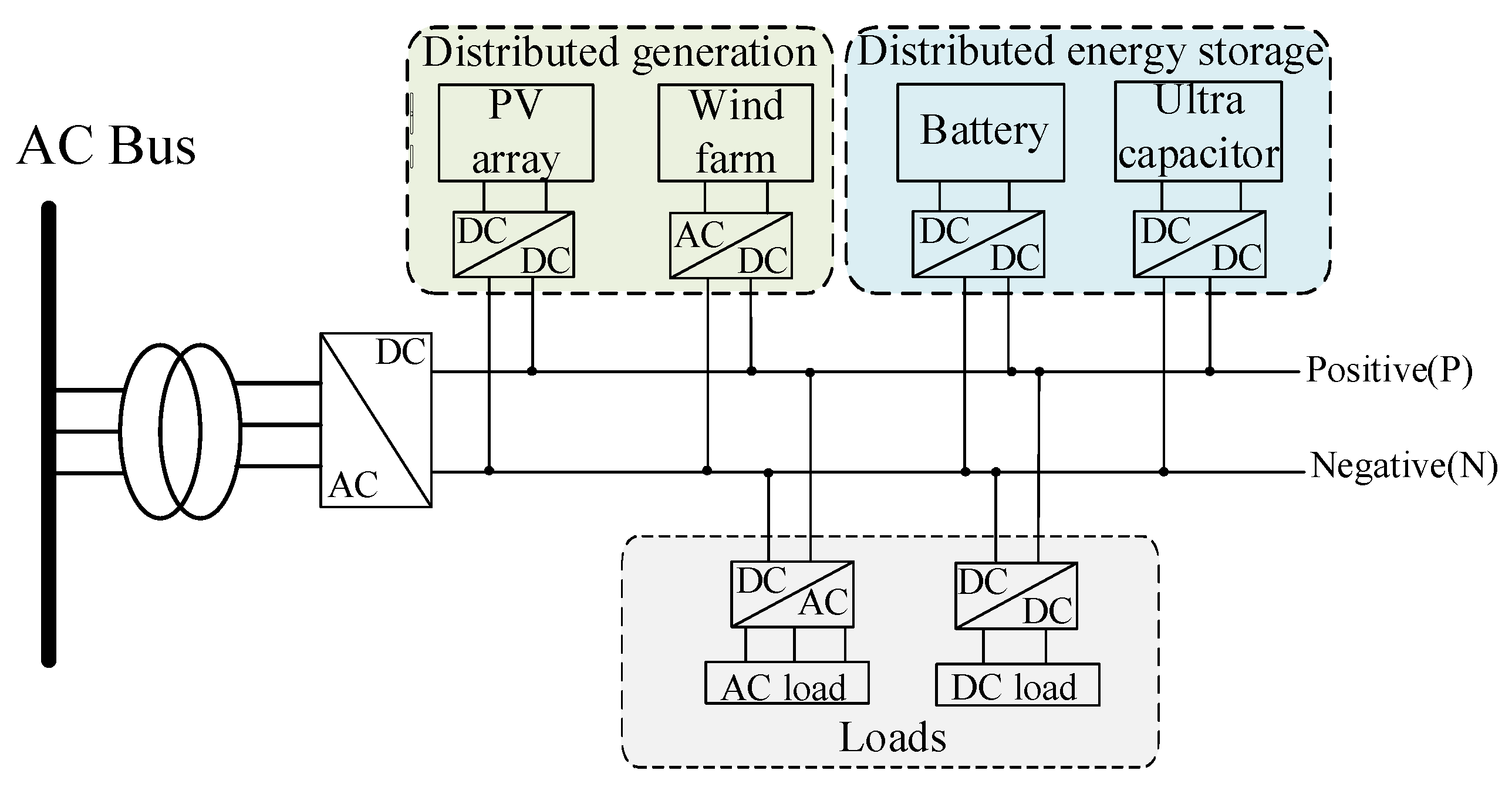
The application of DC distribution is an effective method of power transmission [1]. With the addition of various DC loads, it can be found that the efficiency of the DC distribution network is much higher [2]. With the development of a DC microgrid, the DC distribution system has attracted more attention [3]. The structure diagram of a traditional DC distribution network is presented in Figure 1. Compared with the AC distribution system, it has many advantages [4]:
- The DC distribution system has fewer power conversion stages, which can reduce power losses [5];
- In a DC distribution system, renewable energy sources (RESs), electric vehicles and other DC loads are easier to join the power system [6];
- The DC distribution system can avoid the difficulty of frequency and phase synchronization that the AC system often needs to consider [7].
According to the number of DC buses, the existing DC distribution network system can generally be divided into two types of DC bus frames: unipolar and bipolar DC bus configurations [8]. In the three-wire bipolar DC distribution network, the configuration has one more neutral bus than the unipolar DC distribution network. Therefore, the bipolar DC distribution network will not adopt only one voltage level in the same way as the unipolar DC distribution network. A bipolar DC distribution network can provide two voltage levels with fewer buses: the pole-to-neutral and the pole-to-pole voltage [9]. Application of the bipolar DC structure can effectively reduce the power conversion and improve the overall efficiency [10]. In this case, the distributed generation (DG), green buildings and electric vehicle charging stations can be more flexibly integrated to improve the utilization of the DC power system [11]. Meanwhile, the conduction losses are four times lower than those of the two-wire unipolar DC distribution system [12]. In the structure of a bipolar DC distribution network, similar to the three-phase AC system, multiple voltage levels are provided, which will greatly improve the stability of the system due to the independent operation of the two poles [13]. Moreover, even when one of the DC buses fails, the other two lines can ensure the normal operation of the system [14].
Despite the advantages of a bipolar DC distribution network, there is still the unique power quality problem of positive and negative unbalanced voltages in practical operation [15]. The difference between the DC loads and RESs in a bipolar DC distribution network will lead to a neutral line unbalanced current and further lead to the voltage deviation of different nodes [16]. The unbalanced voltage will also increase the power loss of the system and accelerate the aging speed of the instruments [17]. Therefore, it is necessary to adopt an appropriate method to regulate the unbalanced voltage in the bipolar DC distribution network.
According to the existing literature, there are three types of control methods for adopting devices for the suppression of an unbalanced voltage. The comparison of different control methods is presented in Table 1, and they are as follows:
- Compensation device: an electric spring (ES) is introduced as compensation equipment in a bipolar DC distribution network;
- Switching device: serial and parallel automatic commutation switch methods are adopted to control the unbalanced voltage;
- Interconnection device: VSC and power flow controllers are interconnected with the bipolar DC distribution network to control the unbalanced voltage.
For the method of compensation device, the DC ES is introduced to alleviate the unbalanced voltage caused by a constant power load (CPL) in the bipolar DC distribution network [18]. Due to the existence of the neutral line in a bipolar DC distribution network, the positive and negative voltages are coupled. This method can improve the stability of the system. In [19], the ES was applied to the control of the unbalanced voltage and power losses in the bipolar DC distribution network. Through the proposed method, the control system was simplified, and the anti-interference ability of the system was improved. However, the regulation effects of ES in [18,19] were seriously influenced by the battery capacity and power of the non-critical load.
For the switching device, the authors of [20] proposed a method to regulate the unbalanced voltage and current. The serial automatic commutation switch (ACS) was applied in the control method to adjust the power polarity of the DC loads. Subsequently, the effectiveness of the proposed control method was verified through the simulation results. However, additional switches were required for the proposed control system, which would increase the cost. On the basis of ACS and a genetic algorithm, an unbalanced DC load parallel switching control method was proposed in [21]. The proposed method can suppress the unbalanced loads, voltages, currents and power losses considerably. However, each node needs to be collected, and the operation is rather complex.
For the interconnection device, a buck three-level converter of the proposed model is adopted to assess the power conversion efficiency in the unbalanced bipolar DC microgrid [22]. However, compared with the two-level converter, the three-level converter has higher complexity and a higher cost. In [23], a strategy to realize power flow control (PFC) of the DC distribution network and balance of the positive and negative voltage or power is proposed. The application of series-parallel PFC in a bipolar DC distribution system is studied. Under the constant voltage control, the proposed method can achieve the regulation of the unbalanced currents and flexible control of DC PFC in the bipolar DC distribution network. However, the proposed method of series-parallel PFC cannot regulate the unbalanced voltage of the end nodes adequately.
The existing research on consensus control in a DC microgrid has made considerable progress. In [24], a new deep learning model was proposed for consensus control prediction to adjust the SOC in a DC microgrid to ensure the stable operation of the power system. However, this model requires a huge amount of training data, which increases the workload and complexity. The authors of [25] proposed consensus control considering the average voltage droop value due to line resistance and droop gain. This control structure can ensure the normal operation of the whole power system under fault conditions and system disturbances, which shows its strong robustness. A distributed timing secondary controller based on the average consistency algorithm was introduced in [26]. The controller can update the control gain independently and realize the voltage regulation of the DC bus, and the secondary controller can accelerate the convergence and ensure the power system is more stable. However, the authors only consider the DC distribution network in island mode, and the radial DC distribution network with an AC source is not considered.
In order to balance the bus voltage and current to ensure the system operates safely within the rated range, a voltage balancer (VB) can be introduced into a bipolar DC distribution network [27]. The VB can supply power to the positive and negative poles while ensuring the pole-to-neutral voltages are equal in a bipolar DC distribution network [9]. The above references do not discuss the structure of the circuit when multiple VBs participate in a radial multi-node bipolar DC distribution network, nor do they discuss the voltage or current unbalance coefficients. Normal operation of the bipolar DC distribution network needs VBs with large capacities. If the positive and negative power deviation is too large, the positive and negative voltage difference will be too large, and the VBs must be large enough to eliminate the deviation. In a bipolar DC distribution network, when one VB fails, the other VBs should be able to balance the bus voltage. Further research is needed on the control of multiple VBs involved in regulating the bus voltage balance.
This paper proposes an optimized consensus control structure based on a sparse communication network, and the main contributions of this study are as follows:
- A radial multi-node bipolar DC distribution network with multiple VBs is constructed. This radial grid structure has only one AC main power supply. The AC main power supply can be cut off when it fails, and the rest of the DC side can be used as an island system and operate independently.
- The positive and negative current formula of the multi-node bipolar DC distribution network is derived, and the effects of the line resistance, load resistance, and VB switching duty ratio on the positive and negative current and stability of the system are discussed.
- The secondary control based on the consensus algorithm with a sparse communication network is applied in a radial multi-node bipolar DC distribution network. The droop coefficient of the primary control is adjusted, and the voltage of the VB is controlled to ensure the stable operation of the power system.
The remaining structure of this paper is divided into four sections. Section 2 introduces the structure of the radial multi-node bipolar DC distribution network and analyzes the influence of the line resistance, load resistance and duty cycles of the switches in the VBs on the DC bus current. In Section 3, the VB dynamic equations are analyzed, and the secondary control based on the consensus algorithm is constructed. Subsequently, the structure of the primary and secondary control is synthesized. Section 4 shows the simulation results. Section 5 is a summary of this paper.
2. Configuration of the Bipolar DC Distribution Network and Discussion on the DC Bus Current
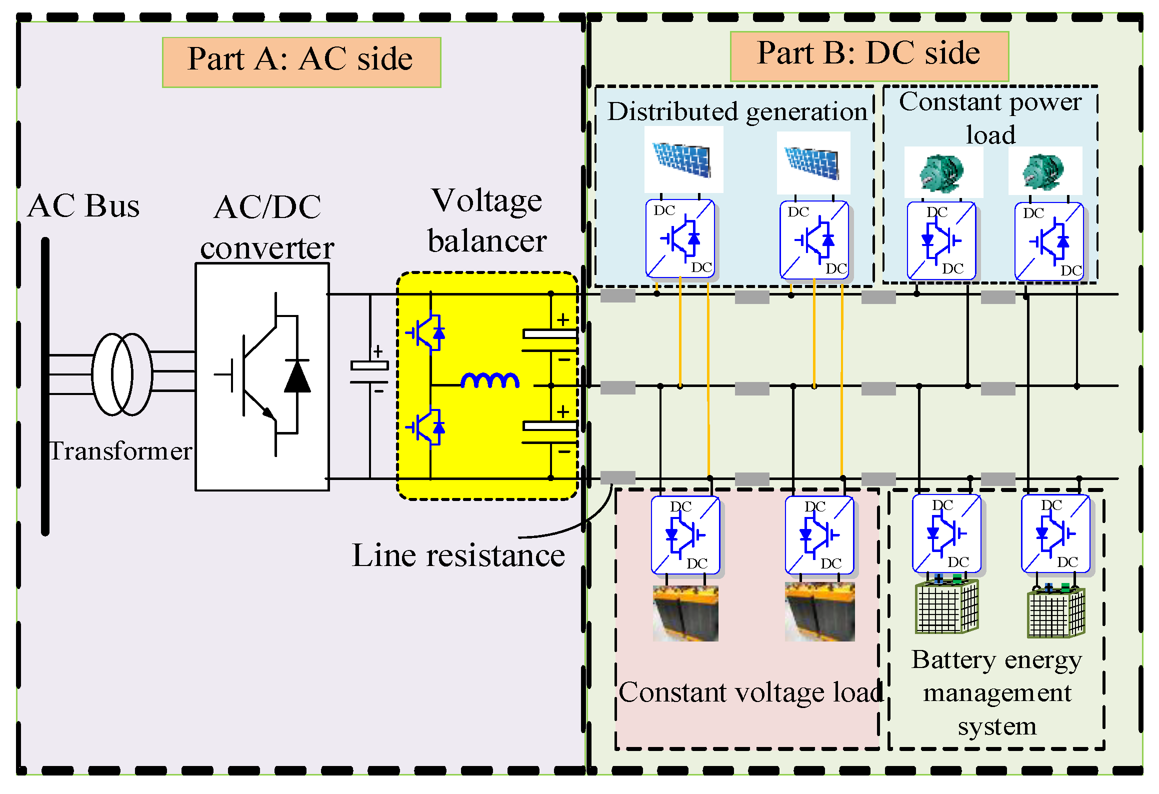
A configuration of the radial multi-node bipolar DC distribution network with VBs is proposed in Figure 2. The proposed configuration of a DC distribution system includes the following parts: the AC source provides AC voltage; an AC/DC converter transfers the AC voltage to DC bus voltage; the VB converts the unipolar DC bus voltage into a three-wire bipolar DC voltage after regulation; and the DGs, energy storage system, constant power loads (CPL) and constant voltage loads (CVL) are connected to the bipolar DC distribution network system.
Figure 3 shows a structure diagram of the radial bipolar DC distribution network with VBs, including the distributed generation part and AC grid part. The PV power can serve as an RES. The unipolar DC voltage generated by the PV array is boosted by DC/DC converter and then converted into the three-wire DC bus voltage by the VB. For the AC grid part, the AC bus voltage is converted to unipolar DC bus voltage by an AC/DC converter and then converted into the three-wire bipolar DC bus voltage by the VB.
In a bipolar DC distribution network, the DC bus voltage and current deviation are important indexes to measure the power quality and power balance. The positive and negative unbalanced power supply, load and line resistance will lead to the unbalanced DC bus current and further increase the voltage deviation. The increase in the unbalanced current and voltage will seriously affect the normal operation of the system, which needs to be controlled. Therefore, the application of the voltage and current unbalance coefficient to evaluate the stability of the bipolar DC distribution network is significant. If the voltage unbalance coefficient is too large and exceeds the rated value, it will cause a large power loss and have a negative influence on the operation of loads [28]. According to ANSI C84, when the voltage unbalance coefficient is less than 3%, the system will operate stably in the whole process. The equation of the voltage and current unbalance coefficient is given in [29,30]:
where Udp and Udn are the positive and negative bus voltages, respectively. Idp and Idn are the positive and negative bus currents, respectively.
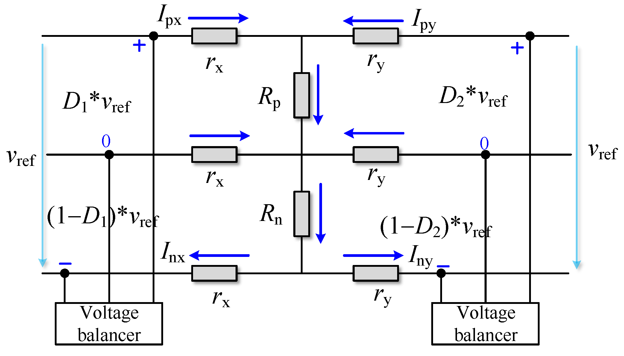
In order to further study the current unbalance coefficient in the power system, it is necessary to obtain the relationship between the positive and negative currents in the bipolar DC distribution network. The simplified structure of Figure 4 is obtained by modeling the VB in Figure 3.
For the convenience of calculation, two nodes were adopted for discussion in this model. The duty cycle of the two switches in one VB discussed was complementary. Therefore, the positive and negative voltage of node 1 were set to D1uref and (1 − D1)uref, respectively, and the positive and negative voltage of node 2 were set to D2uref and (1 − D2)uref, respectively. The equation was obtained according to Kirchhoff’s law from Figure 4:
where D1 and D2 are the duty cycles of the positive switch of node 1 and node 2, respectively; uref is the rated value of the voltage difference between the positive and negative buses of a bipolar DC distribution network; Ipx and Inx are the positive and negative currents of node 1, respectively; Ipy and Iny are the positive and negative currents of node 2, respectively; rx and ry are the line resistance of node 1 and node 2, respectively; and Rp and Rn are the positive and negative load resistance between node 1 and node 2, respectively.
According to Equation (2), it can be concluded that the positive and negative line currents of node 1 and node 2 meet the following criteria:
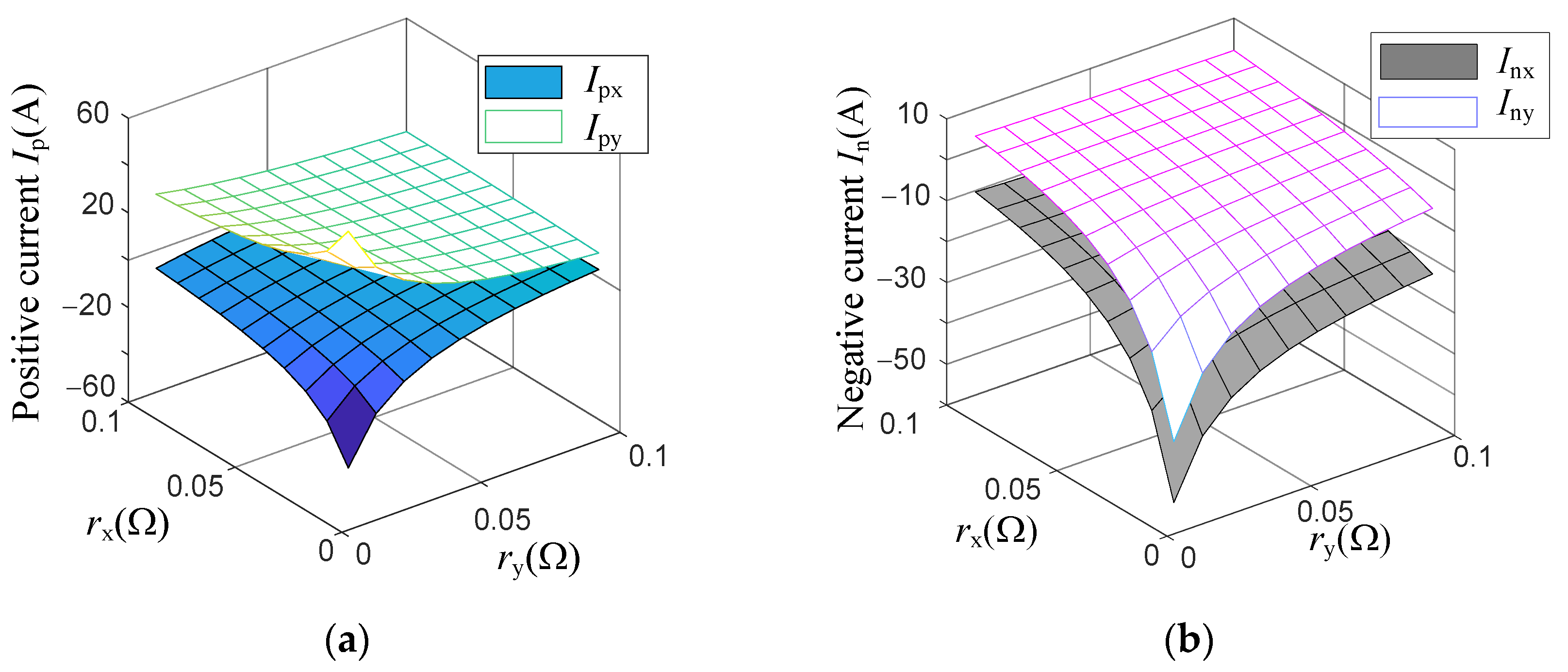
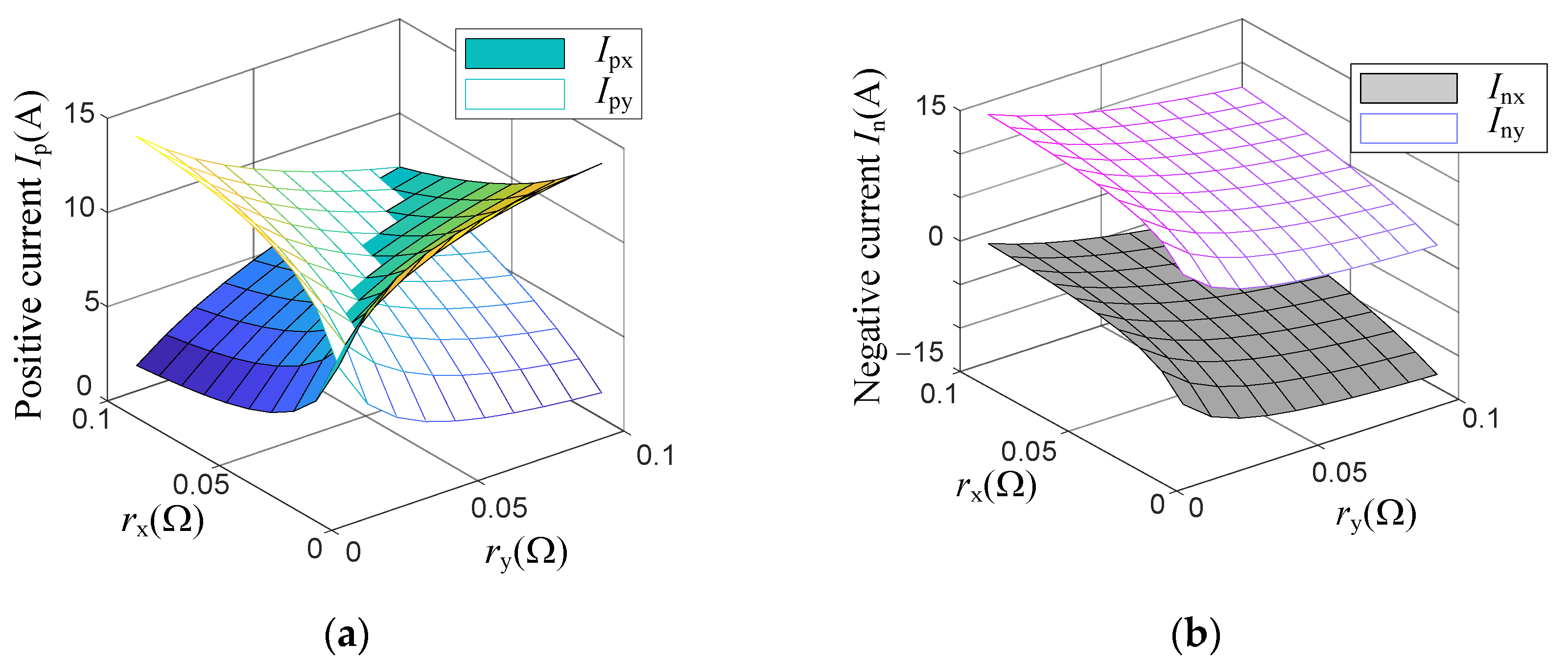
The specific effects of the duty cycles, line resistance and load resistance on the positive and negative line currents could be obtained from Equation (3) by setting the value range of both rx and ry to [0.01–0.1] Ω. The rated value of the voltage uref was 30 V, and the load resistance Rp and Rn were both 1 Ω. When D1 and D2 were not equal (setting D1 = 0.45, D2 = 0.55), the variation curve of the positive and negative DC bus currents of node 1 and node 2 could be obtained according to Equation (3). The results are presented in Figure 5.
As can be seen from Figure 5a, the changing trends of the positive currents of node 1 and node 2 were opposite, and the difference between them increased with the decrease in rx and ry. Figure 5b shows that the changing trends of the negative currents of node 1 and node 2 were the same, and their difference was almost the same with the change in rx and ry. In this condition, the bipolar DC distribution network system was in an unbalanced state. Therefore, the different duty cycle had a non-negligible impact on the currents of the bipolar DC distribution network.
In order to study the influence of the line resistance and load resistance on the power system and eliminate the influence of the duty cycle, we set D1 = D2 = 0.5. In this condition, the proposed VB model was in equilibrium, and Equation (3) could be simplified to
Figure 6 presents that when the duty cycles D1 = D2 = 0.5, the absolute values of the positive and negative currents of node 1 and node 2 were equal. In this case, the absolute values of the currents of node 1 and node 2 were not equal. In order to coordinate multiple VBs to balance the power system in a radial multi-node bipolar DC distribution network, it was necessary to add a secondary control based on a consensus algorithm to the bipolar DC distribution network.
3. Design of Primary and Secondary Controllers for the Multi-Node Bipolar DC Distribution Network
3.1. Small-Signal Analysis of the Voltage Balancer
The proposed bipolar DC distribution network with a half-bridge VB structure can keep the balance of the positive and negative DC bus currents when the duty cycles between nodes are equal. However, due to the existence of line resistance (RL) and load resistance, there must be deviations between the bus voltages. In order to solve the unbalanced voltage and current, the derivation formula of the control scheme for a half-bridge VB was adopted. Through analysis and calculation, the relevant parameters of the primary control in Figure 7 could be obtained. In this paper, uppercase letters represent the steady state parameters, such as how Ipx and Inx are the positive and negative currents of node 1 under a steady state, respectively, and lowercase letters represent dynamic parameters, such as how iL is the input current of the inductor in the VB, up, and un are the positive and negative bus voltages under a dynamic state, respectively, and represent the small disturbance parameters of the duty cycle, negative bus voltage, current of the inductor and DC bus voltage, respectively [31].
Figure 3 presents the structure of the bipolar DC distribution network with a half-bridge VB. When the constructed grid structure was in normal operation, the switches Q1 and Q2 in the VB adopted complementary PWM control, because the main objective of this study was to ensure the balance of positive and negative bus voltages in the bipolar DC distribution network. By setting the duty cycle of the switch Q1 to d1, the duty cycle of the complementary switch Q2 was (1 − d1). According to the structure of the bipolar DC distribution network in Figure 3, the average equation of the VB of node 1 is as follows:
where iL is the input current of the inductor in the VB, iN is the output current of the inductor in the VB, which is also the neutral line current, up and un are the positive and negative bus voltages, respectively, C1 and C2 are the positive and negative capacitances, respectively, d1 and (1 − d1) are the duty cycles of switches Q1 and Q2, respectively, L is the inductance of the VB and udc is the difference the voltages of the positive and negative poles.
When C1 and C2 are equal, the voltage deviation of the bipolar DC distribution network can be reduced, and the calculation of the power system transfer function can be simplified:
In order to design the controller of the circuit loop as shown in Figure 7, it was necessary to build a model and analyze the small signal of the proposed half-bridge VB:
By combining Equations (6) and (7), the small-signal simulation equation of the AC state for the half-bridge VB could be obtained:
Then, the transfer function of the controller could be expressed as
3.2. Consensus Control of the Voltage Balancers in the Multi-Node Bipolar DC Distribution Network
From the influence results of the line resistance and load resistance on the positive and negative bus currents in Section 2, the voltage and current balance of the bipolar DC distribution network needed further control system influence. In order to solve this problem, this paper adopts the distributed consensus control combining primary control and secondary control.
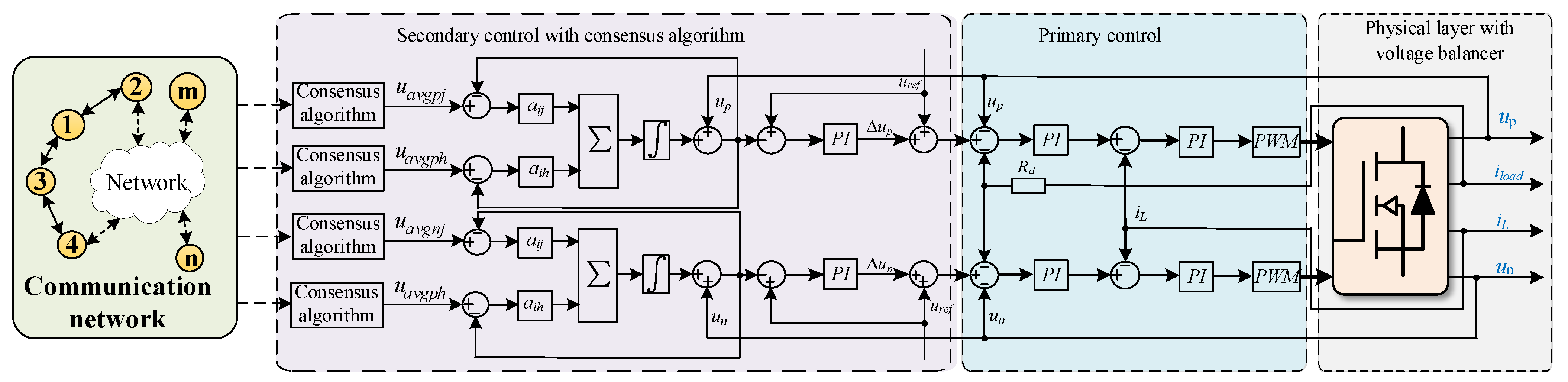
Figure 7 presents that in the multi-node bipolar DC distribution network, the balance of the positive and negative DC buses could be realized through the consensus control of multiple parallel VBs. In order to realize the control function of multiple VBs, it was necessary to apply a sparse network in a bipolar DC distribution network system. The existence of line resistance and load resistance would aggravate the bus voltage deviation of the bipolar DC distribution network.
The primary control part in Figure 7 adopts the voltage and current double closed-loop structure, in which the outer loop is the voltage loop and the inner loop is the current loop. The inputs of the voltage loop are the positive and negative voltage error. After the PI control, the current reference value of VB is obtained. Then there is the current loop, which also applies PI control, and the output is the duty cycle signal of Q1. The primary control cannot fully ensure the balance of the positive and negative DC bus voltages. The proposed secondary control in Figure 7 is a distributed control based on the consensus control principle, which further controls the voltage generated by the primary control. This control can realize consensus control through data information exchange between adjacent contacts. Here, i and j represent two adjacent distributed generators in a bipolar DC distribution network. Its data information exchange principle is as follows:
where ξi and ξj represent the state variables of node i and node j, respectively, and aij is the communication weight of the information exchange between node i and node j.
Due to the existence of the line resistance and loads mentioned above, there will be deviations in the positive and negative DC bus voltages. Therefore, it is more effective to adopt the average value of the DC bus voltage to participate in the secondary control in the bipolar DC distribution network. The secondary control not only needs to provide a reference voltage for the primary control but also adjust the average voltage of the DC bus. According to the average consensus algorithm, the average voltage of the positive and negative DC buses of the ith half-bridge VB can be obtained as follows:
where upi and uni are the positive and negative DC bus voltage of the ith half-bridge VB, respectively, node i and node j are connected through a sparse network under consensus algorithms and uavgpi, uavgpj, uavgni and uavgnj are the average output voltages of the positive and negative buses of the ith and jth half-bridge VB, respectively.
The secondary control system will regulate the average output voltages of the DC buses according to the state information of adjacent distributed power generations. The errors between the DC bus reference voltage uref and the average voltage uavgpi and uavgni of the positive and negative DC buses are obtained. Then, the correction values of the positive and negative DC bus voltages are generated through the PI controller. When the DC bus reference voltage uref is greater than the average DC bus voltage of the VB, the correction value is positive, which means the output value of the PI controller will increase the reference voltage of the voltage droop control and then increase the average DC bus voltage of the VB:
where Δupi and Δuni are the positive and negative bus voltage correction values, respectively, and kPpi, kPni, kIpi, and kIni are the proportional coefficient and integral coefficient of the PI controller in the secondary control system at the positive and negative poles of node i, respectively.
3.3. Stability Analysis of the Bipolar DC Distribution Network
In order to study the effectiveness of the proposed control structure on the stability of the multi-node bipolar DC distribution network, the small-signal model of the control strategy is investigated. In addition, the root locus and Nyquist plot are also shown to analyze the stability. To facilitate analysis, in the proposed bipolar DC distribution network, the DG was connected to the DC bus through a DC/DC converter and VB without considering the switching loss and line loss. The power equation of the VB can be expressed as follows:
According to Equation (13), the linearization equation can be obtained:
where up0 and un0 are the positive and negative bus voltages at a stable state, respectively, and ip0 and in0 are the positive and negative currents of the loads under a stable state, respectively.
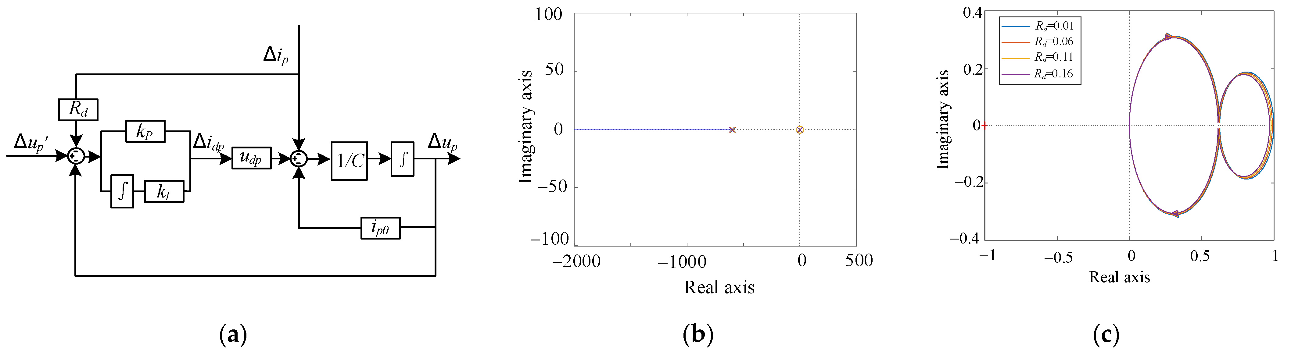
According to Equation (14), the primary control dynamic structure diagram of the control system can be obtained (Figure 8a). The reference voltage Δup′ and the load current Δip served as the inputs. Meanwhile, the positive DC bus voltage was the output of the primary control system. Then, the transfer function of the primary control can be expressed as follows:
where Gp and Gn represent the positive and negative transfer functions of the primary control, respectively; kP and kI are the proportional coefficient and integral coefficient of PI in the primary control, respectively; and Rp and Rn are the positive and negative loads. The related parameters in the multi-node bipolar DC distribution network are shown in Table 2 and Table 3.
Based on the above small-signal analysis, the influence of the parameters under the primary control system on the stability of the DC distribution network was investigated. Considering that the control parameters of the converter were optimized, the influence of the change of the parameters kP and kI on the stability performance of the system was not taken into account. Figure 8b,c illustrates the root locus and Nyquist plot when the droop coefficient changes from 0.01 to 0.2, respectively. With the droop coefficient Rd varying from 0.01 to 0.2, the zeros and poles of the root locus system were located in the negative half plane, and the Nyquist curve did not surround the point (−1, j0). Therefore, the system under primary control was stable. According to [32], with the increase in the droop coefficient, the shunt accuracy of the system would improve, but the voltage unbalance coefficient would be increased. The main focus of this paper is to investigate the voltage unbalance coefficient of the bipolar DC distribution network under primary control with proposed consensus control. The subsequent simulation results in Section 4 will prove that after adding consensus control, the voltage unbalance coefficient will be much better than only adopting traditional droop control, even if the droop coefficient taken in traditional droop control is small. Therefore, the value of the droop coefficient does not need to be large, which was selected to be 0.02 in this paper.
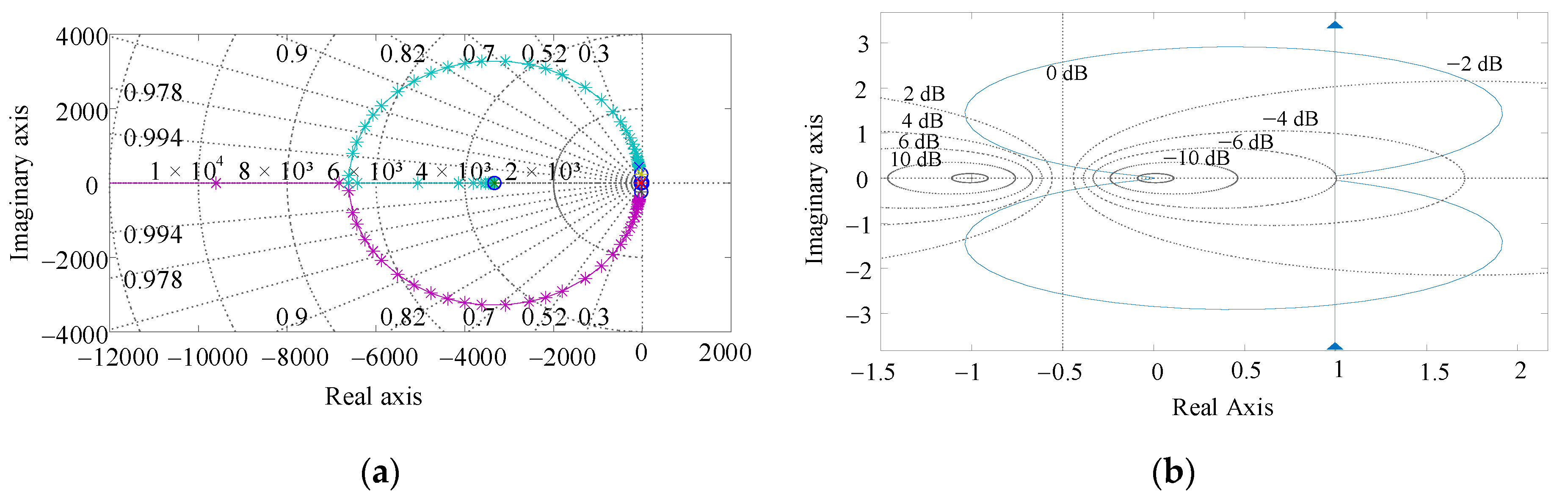
Subsequently, the state space model of the proposed bipolar DC distribution network with primary and secondary control could be obtained. The stability of the proposed control system could be verified through the root locus plot and Nyquist plot, which are shown in Figure 9. It can be seen from Figure 9a that the zeros and poles of the root locus system were located in the negative half plane. According to Figure 9b, the Nyquist plot of the proposed system did not surround the point (−1, j0). Therefore, from analysis of Figure 9, the proposed bipolar DC distribution network with the control system was stable.
4. Simulation Results
In order to verify the effectiveness of the coordinated management strategy of multiple voltage balancers based on the combination of consensus control and droop control proposed in this paper, a four-node bipolar DC distribution network experimental system with four VBs in parallel was built in MATLAB/Simulink. The parameters adopted in the simulation were the same as those in Table 2, and the rest of the parameters regarding the different loads of each node are shown in Table 3.
4.1. Comparison of the Results between Traditional Droop Control and Consensus Control
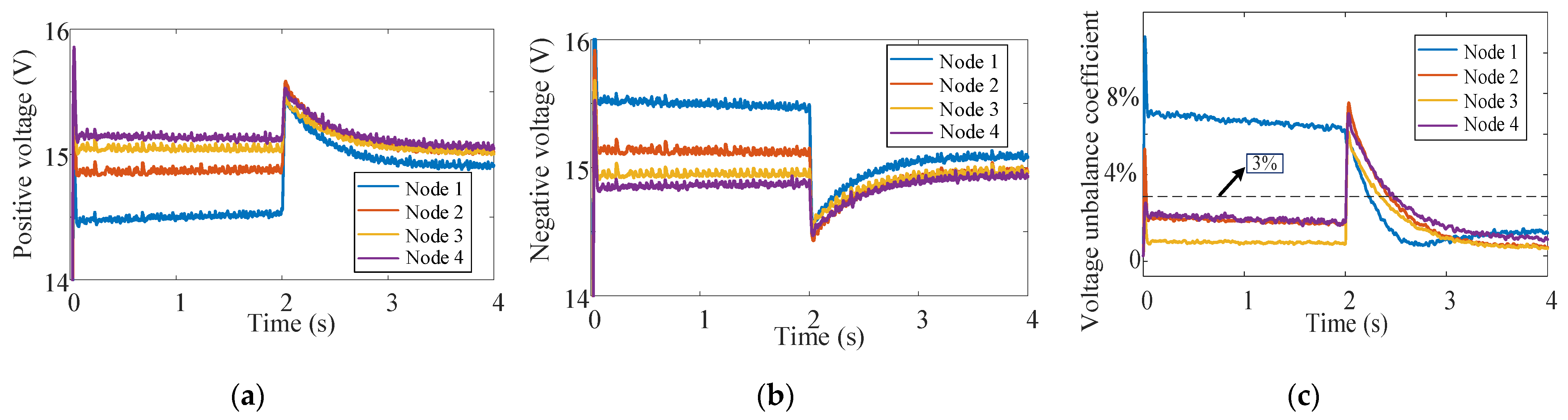
In order to verify the effectiveness of the unbalanced voltage control strategy on the basis of consensus control for VBs proposed in this paper, a comparative analysis was made between the system that only adopted droop control and the system that added secondary control based on consensus control. From 0 s to roughly 2 s, only the primary control of voltage droop control was used for the bipolar DC distribution system to regulate the voltage deviation. After 2 s, the secondary control based on consensus control proposed in this paper was added to the bipolar DC distribution network. The simulation results are shown in Figure 10.
It can be seen from Figure 10 that during 0~2 s, due to the influence of the line resistance and load resistance in the multi-node bipolar DC distribution network system, the positive and negative DC bus voltage of each node would deviate from the rated value of 15 V. By adopting the discussion of the voltage unbalance coefficient in Section 2, it was concluded that the sum of the voltage unbalance coefficients of the four nodes was larger than the rated value (12%):
Additionally, the voltage unbalance coefficient of node 1 was nearly 7%, far exceeding the upper limit value of 3%, which means the bipolar DC distribution network system was not in a stable condition.
After 2 s, the secondary control based on the consensus algorithm was added to the control system. Then, the positive DC bus voltages had an increasing trend approaching 15 V, the negative DC bus voltages had a decreasing trend approaching 15 V, and the overall trend of the voltage unbalance coefficient was a decreasing one. The voltage unbalance coefficients were all within the rated range of 3%, and the sum of the voltage unbalance coefficients was much smaller after 2 s:
Although there were still deviations between the DC bus voltages and the rated voltage of 15 V after 2 s, the deviations of all nodes were significantly reduced and remained below 3%. This proves the effectiveness of consensus control in a multi-node bipolar DC distribution network.
4.2. Effect of Consensus Control on the Average Output Voltage
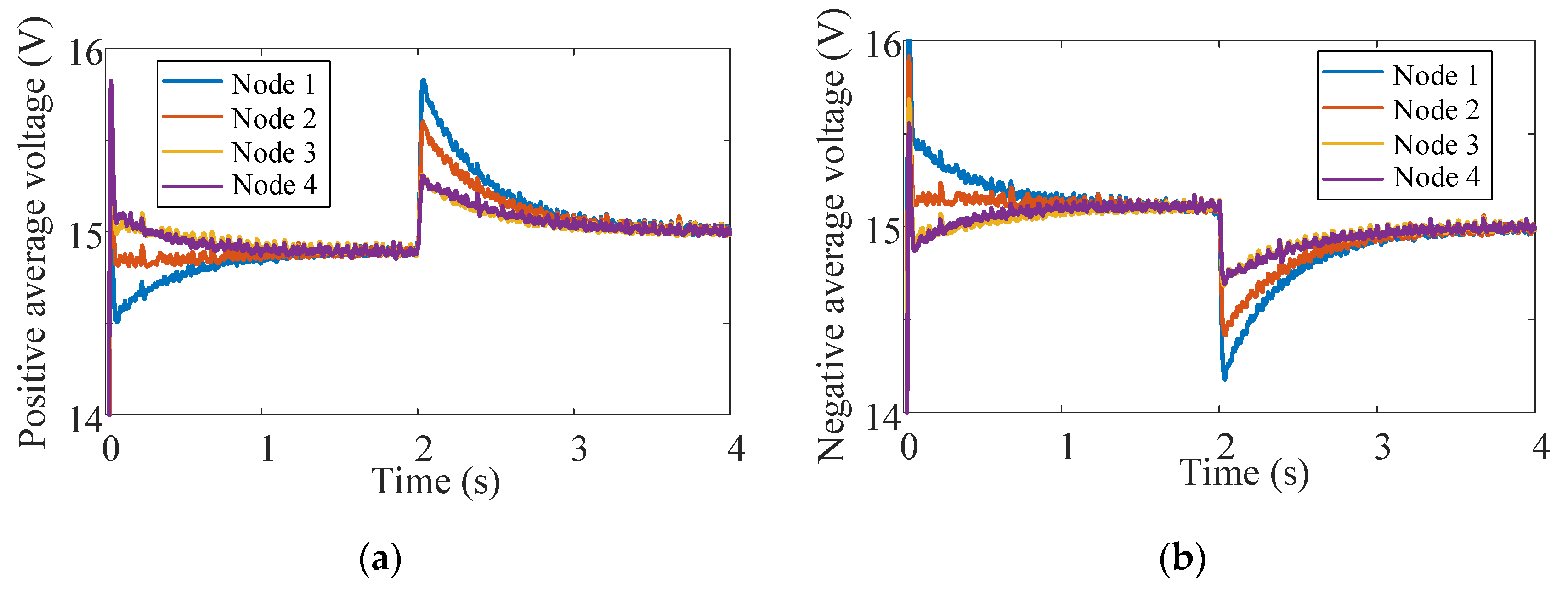
This case was designed to show the performance of the proposed distributed consensus control combining primary control and secondary control. In the control system, the multiple parallel VBs under the information exchange of a sparse network could realize the balance of the positive and negative DC buses.
It can be seen from Figure 11 that the average voltage of the positive and negative buses shifted to 14.9 V due to the existence of line resistance and load resistance. Then, consensus control was adopted, and the average voltage of the positive and negative buses was raised to 15 V to reach balance control. The results demonstrate that the proposed secondary control could not only provide a reference voltage for the primary control system but also exert the consistency of the secondary control system to adjust the average voltage of the DC bus to reach the rated value of 15 V.
4.3. Influence of the Load Switching on the Multi-Node Bipolar DC Distribution Network
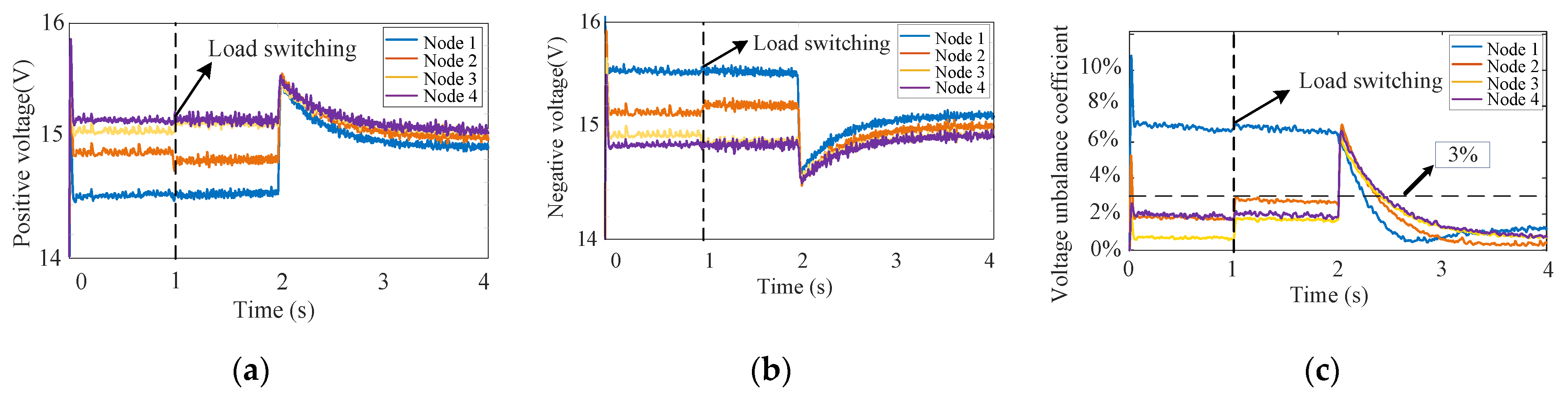
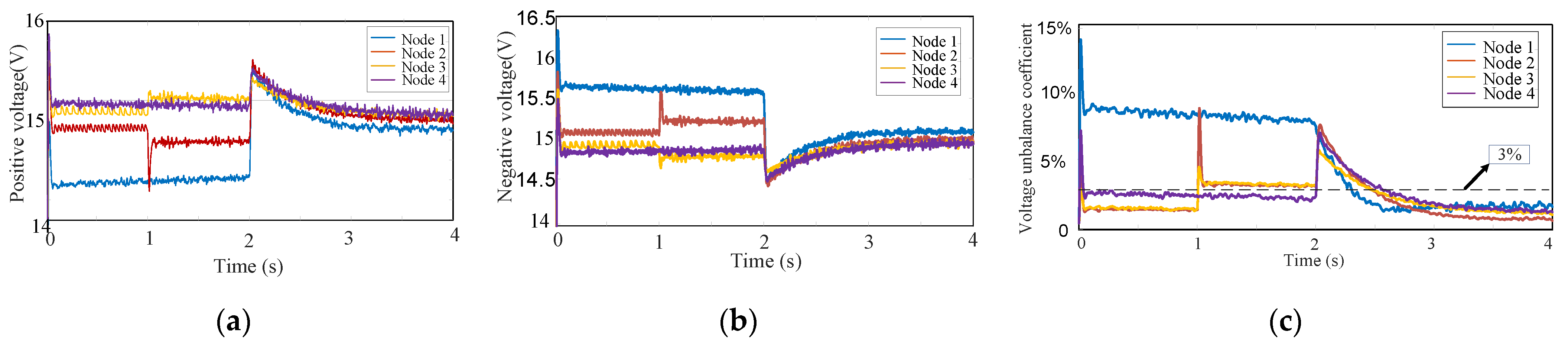
This case was designed to analyze the effects of different control methods when the load switched in a multi-node bipolar DC distribution network. In the initial stage of 0~1 s, the system only adopted traditional droop control for primary control. In the 1~2 s phase, the additional switching loads (Rsp = Rsn = 5 Ω) were placed between the positive and negative poles of node 2 and node 3. In the last stage of 2 s~4 s, the secondary control based on the consensus algorithm was adopted in the network. The simulation results are shown in Figure 12.
Figure 12 presents that the change in the positive and negative bus voltages in the initial stage of 0~1 s was the same as that under condition A. In the 1~2 s phase, all the voltage unbalance coefficients of the four nodes increased for the interference of additional loads. The unbalance coefficient of node 1 reached 7.5%, which was much higher than the rated value of 3%, which means that the bipolar DC distribution network system was in an unstable state. This stage shows that the control system only adopted droop control, as the primary control could not effectively control the unbalanced voltage. In the last stage of 2 s~4 s, consensus control was applied in the control system. The change trends of the positive and negative DC bus voltages of the four nodes were the same as that of case A; the positive voltages had an upward trend which approached 15 V, and the negative voltages had a downward trend which also approached 15 V. In addition, the voltage unbalance coefficients were reduced and nearing 0%. In order to quantitatively analyze the effectiveness of consensus control on the positive and negative bus voltages, the method of calculating the total voltage unbalance coefficient in case A was applied in this case:
After the load switching in the multi-node bipolar DC distribution network, the whole system could still significantly reduce the voltage unbalance coefficients of all nodes and keep them within the rated range, which proves the effectiveness of consensus control.
Figure 13 presents the sum of the power losses of the four nodes on the neutral line. When the loads were switched at 1 s, the power loss on the neutral line was reduced. After 2 s, the proposed consensus control was added, and the power loss on the neutral line was further reduced. Figure 14 illustrates the changes in the positive and negative load voltages and voltage unbalance coefficients when the DC bus rated voltage changed from 30 V to 60 V. As can be seen from Figure 14, the positive and negative load voltages changed twice as much as before, and the changing trend was consistent with Figure 12a,b. Moreover, the voltage unbalance coefficients were consistent with Figure 12c. According to the analysis, it can be proven that the proposed control system had good effectiveness.
4.4. Effects of Consensus Control on the Excessive Line Resistance
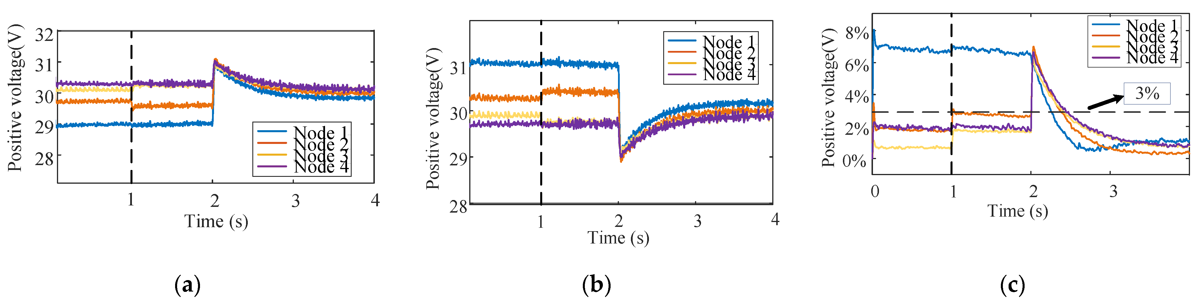
Grid failure will cause the line resistance to increase, resulting in a dangerous situation for the power system. This case was applied to verify that the proposed control strategy could effectively control the bus voltage and voltage unbalance coefficient. In this simulation, we set the line resistance to be much larger than before (e.g., 10 times the size of the previous resistance). The rest of the circuit design was the same as that in case C. During the 0~1 s interval, we only adopted droop control in the system; in the 1~2 s interval, we put the additional loads (Rsp = Rsn = 5 Ω) between node 2 and node 3; and in the 2~4 s interval, the coordinated control based on the combination of primary control and secondary control on the basis of a consensus algorithm was adopted. The obtained results are presented in Figure 15.
Figure 15 shows that within the 0~1 s interval, the changing trends of the positive and negative bus voltages were the same as those in case C, and the deviation of the voltage was more than before. In addition, the voltage unbalance coefficient of node 1 reached 9%. From 1 s to roughly 2 s, due to the addition of new loads between node 2 and node 3, the voltage unbalance coefficients of all nodes increased. The highest voltage unbalance coefficient of node 2 and node 3 increased to 8.7% and 4.2%, respectively. In this system, only the voltage unbalance coefficient of node 4 was below 3%; it was 2.1%. Then, under the influence of droop control, the voltage unbalance of node 2 and node 3 was reduced to close to 3.2%, still exceeding the maximum upper limit. At this time, the multi-node bipolar DC distribution network was in a severely unbalanced state. Within 2~4 s, the consensus control could exert its ability to control the DC bus voltage. The voltage variation trends of the four nodes were the same as those in case C. All the positive voltages showed an upward trend and were close to 15 V, and the negative voltages showed a downward trend and were close to 15 V. At this time, the voltage unbalance coefficients of the four nodes were all less than 3%, and the total voltage unbalance coefficient could be expressed as
Under the influence of excessive line resistance, the total voltage unbalance coefficient was slightly higher than that in case C, but it was still within the rated range. After applying consensus control in a multi-node bipolar DC distribution network, the whole system could significantly reduce the voltage unbalance coefficient of each node and keep it within 3% of the rated range, which proves the robustness and effectiveness of the proposed control system.
4.5. The Adaptability of Consensus Control to Voltage Unbalance Coefficients
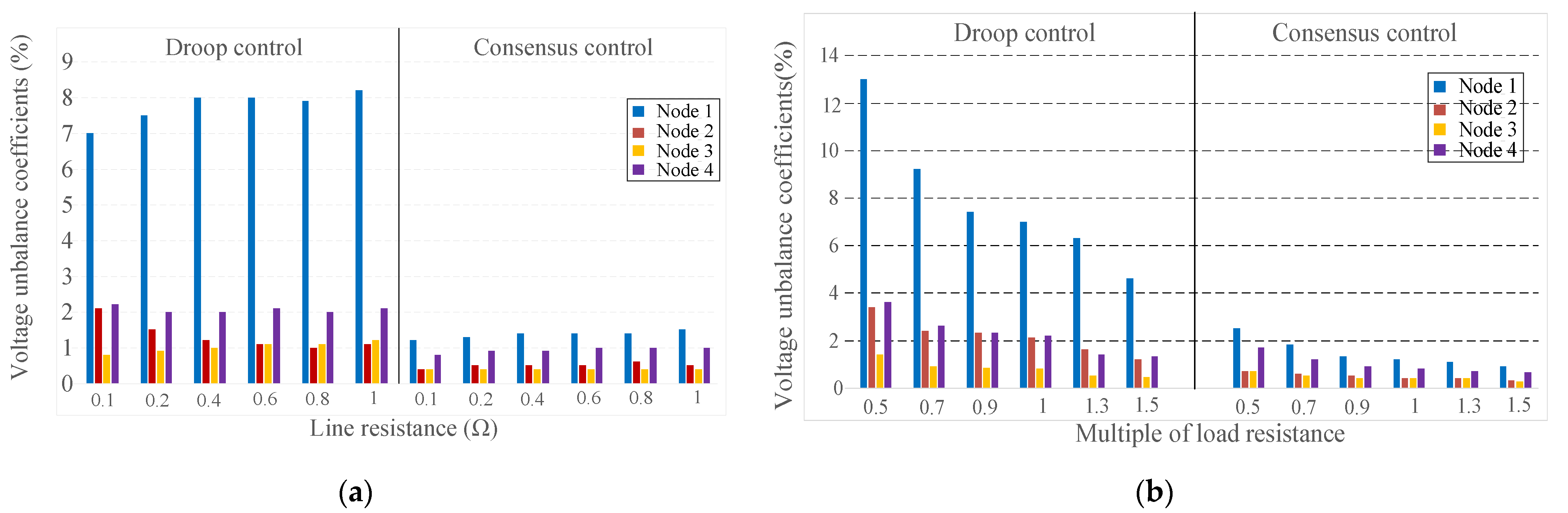
In this case, the adaptability of the proposed consensus control to line resistance and load resistance in a multi-node bipolar DC distribution network will be discussed. We changed the line resistance between 0.1 Ω and 1 Ω and the load resistance to between 0.5 times and 1.5 times the previous value. Then, the voltage unbalance coefficients of the four nodes in the designed system were collected during droop control and consensus control, and we constructed the following histogram.
As can be seen from Figure 16a, although the line resistance was changing, the voltage unbalance coefficients of the four nodes did not change much during droop control or consensus control. After adding consensus control, the voltage unbalance coefficients were significantly reduced. This shows that the designed control system has strong robustness and stability. Figure 16b presents that with the load resistance changing from 0.5 times to 1.5 times, the voltage unbalance coefficients of the 4 nodes decreased during both droop control and consensus control. After consensus control was added, the voltage unbalance coefficients of the nodes decreased significantly. The control system could still maintain effectiveness when the line resistance and load resistance changed in the proposed multi-node bipolar DC distribution network. This shows that the adaptability of the proposed consensus control combining the primary control with the secondary control system was good.
5. Conclusions
This paper proposes a novel consensus control system combining primary control and secondary control of a radial multi-node bipolar DC distribution network with voltage balancers. The proposed system can complete the information exchange of multiple nodes based on a sparse communication system. The voltage balancers can provide multiple voltage interfaces and stabilize the unbalanced voltage of the circuit system. In this paper, the equations of the positive and negative currents and duty cycle of the voltage balancers in a bipolar DC distribution network are deduced, and the effects of the line resistance and load resistance on the power system stability are discussed. The simulation results show that the consensus control can still maintain the stability of the power system after switching the load. The proposed consensus control can also reflect its effectiveness when the line resistance and load resistance change. The designed control system is robust and effective, which is conducive to the stable operation of the bipolar DC distribution network.
Author Contributions
Conceptualization, C.G., J.L. and Y.W.; methodology, C.G. and J.L.; software, C.G. and J.L.; validation, C.G. and J.L.; formal analysis, C.G.; investigation, C.G.; resources, C.G.; data curation, C.G. and J.L.; writing—original draft preparation, C.G.; writing—review and editing, C.G.; visualization, C.G. and Y.W.; supervision, J.L. and Y.W.; project administration, J.L. and Y.W.; funding acquisition, Y.W. All authors have read and agreed to the published version of the manuscript.
Funding
This research received no external funding.
Data Availability Statement
Data is contained within the article.
Conflicts of Interest
The authors declare no conflict of interest. The funders had no role in the design of the study; in the collection, analyses, or interpretation of data; in the writing of the manuscript, or in the decision to publish the results.
References
- Engelen, K.; Shun, E.L.; Vermeyen, P.; Pardon, I.; D’hulst, R.; Driesen, J.; Belmans, R. The Feasibility of Small-Scale Residential DC Distribution Systems. In Proceedings of the IECON 2006—32nd Annual Conference on IEEE Industrial Electronics, Paris, France, 6–10 November 2006; pp. 2618–2623. [Google Scholar]
- Gerber, D.L.; Vossos, V.; Feng, W.; Marnay, C.; Nordman, B.; Brown, R. A simulation-based efficiency comparison of AC and DC power distribution networks in commercial buildings. Appl. Energy 2018, 210, 1167–1187. [Google Scholar] [CrossRef] [Green Version]
- Dragicevic, T.; Lu, X.; Vasquez, J.C.; Guerrero, J. DC Microgrids—Part II: A Review of Power Architectures, Applications, and Standardization Issues. IEEE Trans. Power Electron. 2016, 31, 3528–3549. [Google Scholar] [CrossRef] [Green Version]
- Byun, H.-J.; Park, J.-M.; Kim, B.-J.; Kim, S.-H.; Won, C.-Y.; Yi, J.-S. Small Signal Modeling of Interleaved Voltage Balancer with Coupled-inductor. In Proceedings of the 2020 IEEE Electric Power and Energy Conference (EPEC), Edmonton, AB, Canada, 9–10 November 2020; pp. 1–6. [Google Scholar]
- Loh, P.C.; Li, D.; Chai, Y.K.; Blaabjerg, F. Hybrid AC–DC Microgrids with Energy Storages and Progressive Energy Flow Tuning. IEEE Trans. Power Electron. 2013, 28, 1533–1543. [Google Scholar] [CrossRef]
- Wang, F.; Lei, Z.; Xu, X.; Shu, X. Topology Deduction and Analysis of Voltage Balancers for DC Microgrid. IEEE J. Emerg. Sel. Top. Power Electron. 2016, 5, 672–680. [Google Scholar] [CrossRef]
- Kumar, M.; Srivastava, S.C.; Singh, S.N. Control Strategies of a DC Microgrid for Grid Connected and Islanded Operations. IEEE Trans. Smart Grid 2015, 6, 1588–1601. [Google Scholar] [CrossRef]
- Xu, M.; Ma, K.; Liu, B.; Cai, X. Modeling and Correlation of Two Thermal Paths in Frequency-Domain Thermal Impedance Model of Power Module. IEEE J. Emerg. Sel. Top. Power Electron. 2021, 9, 3971–3981. [Google Scholar] [CrossRef]
- Ma, J.; Zhu, M.; Li, Q.; Cai, X. From “voltage balancer” to “interlinking converter”—A shift of operation concept for distributed bipolar DC system. In Proceedings of the IECON 2017—43rd Annual Conference of the IEEE Industrial Electronics Society, Beijing, China, 29 October–1 November 2017; pp. 1166–1171. [Google Scholar]
- Rivera, S.; Wu, B.; Kouro, S.; Yaramasu, V.; Wang, J. Electric Vehicle Charging Station Using a Neutral Point Clamped Converter with Bipolar DC Bus. IEEE Trans. Ind. Electron. 2015, 62, 1999–2009. [Google Scholar] [CrossRef]
- Gu, Y.; Li, W.; He, X. Analysis and Control of Bipolar LVDC Grid with DC Symmetrical Component Method. IEEE Trans. Power Syst. 2016, 31, 685–694. [Google Scholar] [CrossRef]
- Kakigano, H.; Miura, Y.; Ise, T. Low-Voltage Bipolar-Type DC Microgrid for Super High Quality Distribution. IEEE Trans. Power Electron. 2010, 25, 3066–3075. [Google Scholar] [CrossRef]
- Cui, S.; Lee, J.-H.; Hu, J.; De Doncker, R.W.; Sul, S.-K. A Modular Multilevel Converter with a Zigzag Transformer for Bipolar MVDC Distribution Systems. IEEE Trans. Power Electron. 2019, 34, 1038–1043. [Google Scholar] [CrossRef]
- Prabhakaran, P.; Agarwal, V. Mitigation of voltage unbalance in a low voltage bipolar DC microgrid using a boost-SEPIC type interleaved dc-dc compensator. In Proceedings of the 2016 IEEE 2nd Annual Southern Power Electronics Conference (SPEC), Auckland, New Zealand, 5–8 December 2016; pp. 1–6. [Google Scholar]
- Lee, J.-O.; Kim, Y.-S.; Moon, S.-I. Current Injection Power Flow Analysis and Optimal Generation Dispatch for Bipolar DC Microgrids. IEEE Trans. Smart Grid 2021, 12, 1918–1928. [Google Scholar] [CrossRef]
- Zhang, Z.; Shi, D.; Jin, C.; Koh, L.H.; Choo, F.H.; Wang, P.; Tang, Y. Droop control of a bipolar dc microgrid for load sharing and voltage balancing. In Proceedings of the 2017 IEEE 3rd International Future Energy Electronics Conference and ECCE Asia (IFEEC 2017–ECCE Asia), Kaohsiung, Taiwan, 3–7 June 2017; pp. 795–799. [Google Scholar]
- Yang, X.; Yao, X.; Chen, B.; Lin, Z.; Yan, L. An enhanced reverse blocking MMC with DC fault handling capability for HVDC applications. Electr. Power Syst. Res. 2017, 163, 706–714. [Google Scholar] [CrossRef]
- Liao, J.; Zhou, N.; Wang, Q.; Luo, Y. A Bypass LCC-Based DC Fault Isolation Scheme for Bipolar MMC–HVDC. IEEE Access 2019, 7, 118218–118228. [Google Scholar] [CrossRef]
- Liao, J.; Zhou, N.; Huang, Y.; Wang, Q. Unbalanced Voltage Suppression in a Bipolar DC Distribution Network Based on DC Electric Springs. IEEE Trans. Smart Grid 2020, 11, 1667–1678. [Google Scholar] [CrossRef]
- Liao, J.; Zhou, N.; Huang, Y.; Wang, Q. Unbalanced Voltage Analysis and Suppression Method in a Radial Bipolar DC Distribution Network. IEEE J. Emerg. Sel. Top. Power Electron. 2021, 9, 5687–5702. [Google Scholar] [CrossRef]
- Liao, J.; Zhou, N.; Wang, Q.; Chi, Y. Load-Switching Strategy for Voltage Balancing of Bipolar DC Distribution Networks Based on Optimal Automatic Commutation Algorithm. IEEE Trans. Smart Grid 2021, 12, 2966–2979. [Google Scholar] [CrossRef]
- Broeck, G.V.D.; Martinez, W.; Vecchia, M.D.; Ravyts, S.; Driesen, J. Conversion Efficiency of the Buck Three-Level DC–DC Converter in Unbalanced Bipolar DC Microgrids. IEEE Trans. Power Electron. 2020, 35, 9306–9319. [Google Scholar] [CrossRef]
- Liao, J.; Qin, Z.; Purgat, P.; Zhou, N.; Wang, Q.; Bauer, P. Unbalanced Voltage/Power Control in Bipolar DC Distribution Grids Using Power Flow Controller. In Proceedings of the 2020 IEEE 29th International Symposium on Industrial Electronics (ISIE), Delft, The Netherlands, 17–19 June 2020; pp. 1290–1295. [Google Scholar]
- Alavi, S.A.; Mehran, K.; Vahidinasab, V.; Catalao, J.P.S. Forecast-Based Consensus Control for DC Microgrids Using Distributed Long Short-Term Memory Deep Learning Models. IEEE Trans. Smart Grid 2021, 12, 3718–3730. [Google Scholar] [CrossRef]
- Kumar, V.; Mohanty, S.R. Event Based Robust Action for Fault Restrained Secondary Control of DC Microgrid. In Proceedings of the 2021 14th IEEE International Conference on Industry Applications (INDUSCON), São Paulo, Brazil, 15–18 August 2021; pp. 1379–1384. [Google Scholar]
- Mendis, N.; Muttaqi, K.; Perera, S. Management of Battery-Supercapacitor Hybrid Energy Storage and Synchronous Condenser for Isolated Operation of PMSG Based Variable-Speed Wind Turbine Generating Systems. IEEE Trans. Smart Grid 2014, 5, 944–953. [Google Scholar] [CrossRef]
- Ma, J.; Yan, L.; Miao, Z.; Xu, C. Parallel operation of distributed voltage balancers for bipolar DC system with improved reliability and efficiency. In Proceedings of the IECON 2017—43rd Annual Conference of the IEEE Industrial Electronics Society, Beijing, China, 29 October–1 November 2017. [Google Scholar]
- Gwon, G.-H.; Kim, C.-H.; Oh, Y.-S.; Noh, C.-H.; Jung, T.-H.; Han, J. Mitigation of voltage unbalance by using static load transfer switch in bipolar low voltage DC distribution system. Int. J. Electr. Power Energy Syst. 2017, 90, 158–167. [Google Scholar] [CrossRef]
- ANSI Standard C84.1-1995 (R2001). American National Standard for Electric Power Systems Equipment—Voltage Ratings (60 Hertz); National Electrical Manufacturers Association: Rosslyn, VA, USA, 2006. [Google Scholar]
- Jung, T.-H.; Gwon, G.-H.; Kim, C.-H.; Han, J.; Oh, Y.-S.; Noh, C.-H. Voltage Regulation Method for Voltage Drop Compensation and Unbalance Reduction in Bipolar Low-Voltage DC Distribution System. IEEE Trans. Power Deliv. 2018, 33, 141–149. [Google Scholar] [CrossRef]
- You, X.; Liu, H.; Liao, J.; Huang, Y. An Active Damping Method for the Bipolar DC System Connected with Constant Power Loads. In Proceedings of the 2020 IEEE Electric Power and Energy Conference (EPEC), Edmonton, AB, Canada, 9–10 November 2020; pp. 1–6. [Google Scholar]
- Sharma, S.; Iyer, V.M.; Bhattacharya, S.; Kikuchi, J.; Zou, K. Tertiary Control Method for Droop Controlled DC-DC converters in DC Microgrids. In Proceedings of the 2021 IEEE Energy Conversion Congress and Exposition (ECCE), Vancouver, BC, Canada, 10–14 October 2021; pp. 694–699. [Google Scholar]
Figure 1.
Configuration of a traditional DC distribution network.

Figure 2.
Configuration of the radial multi-node DC distribution network with voltage balancers.

Figure 3.
The system structure diagram of radial bipolar DC distribution with voltage balancers: (A) AC side and (B) DC side.
Figure 3.
The system structure diagram of radial bipolar DC distribution with voltage balancers: (A) AC side and (B) DC side.

Figure 4.
Simplified model of the voltage balancer.

Figure 5.
Influence of line resistance on (a) positive DC current and (b) negative DC current when duty cycles D1 = 0.45 and D2 = 0.55.
Figure 5.
Influence of line resistance on (a) positive DC current and (b) negative DC current when duty cycles D1 = 0.45 and D2 = 0.55.

Figure 6.
Influence of line resistance on (a) positive DC current and (b) negative DC current when duty cycles D1 = D2 = 0.5.
Figure 6.
Influence of line resistance on (a) positive DC current and (b) negative DC current when duty cycles D1 = D2 = 0.5.

Figure 7.
Block diagram of multi-node bipolar DC distribution network with consensus control.

Figure 8.
(a) The structure, (b) root locus, and (c) Nyquist plot of the primary control system with the droop coefficient in the bipolar DC distribution network.
Figure 8.
(a) The structure, (b) root locus, and (c) Nyquist plot of the primary control system with the droop coefficient in the bipolar DC distribution network.

Figure 9.
The (a) root locus and (b) Nyquist plot of the proposed control system in the bipolar DC distribution network.
Figure 9.
The (a) root locus and (b) Nyquist plot of the proposed control system in the bipolar DC distribution network.

Figure 10.
After adopting traditional droop control and adding consensus control, the changes in the (a) positive voltage (b) negative voltage and (c) voltage unbalanced coefficient in multi-node bipolar DC distribution network.
Figure 10.
After adopting traditional droop control and adding consensus control, the changes in the (a) positive voltage (b) negative voltage and (c) voltage unbalanced coefficient in multi-node bipolar DC distribution network.

Figure 11.
The effect of distributed consensus control combining primary control and secondary control on the average voltage of the (a) positive bus and (b) negative bus.
Figure 11.
The effect of distributed consensus control combining primary control and secondary control on the average voltage of the (a) positive bus and (b) negative bus.

Figure 12.
After the load switching, the influence of traditional droop control and consensus control on the multi-node bipolar DC distribution network’s (a) positive voltage, (b) negative voltage and (c) voltage unbalance coefficient.
Figure 12.
After the load switching, the influence of traditional droop control and consensus control on the multi-node bipolar DC distribution network’s (a) positive voltage, (b) negative voltage and (c) voltage unbalance coefficient.

Figure 13.
The sum of power losses of the neutral line.

Figure 14.
When the bus voltage is increased to 60 V, the effects on the (a) positive load voltage, (b) negative load voltage and (c) voltage unbalance coefficient under the proposed consensus control.
Figure 14.
When the bus voltage is increased to 60 V, the effects on the (a) positive load voltage, (b) negative load voltage and (c) voltage unbalance coefficient under the proposed consensus control.

Figure 15.
Under the condition of high line resistance, the influence of traditional droop control and consensus control on the (a) positive voltage, (b) negative voltage and (c) voltage unbalance coefficient.
Figure 15.
Under the condition of high line resistance, the influence of traditional droop control and consensus control on the (a) positive voltage, (b) negative voltage and (c) voltage unbalance coefficient.

Figure 16.
Variation of multi-node voltage unbalance coefficient with (a) line resistance and (b) load resistance under droop control and consensus control.
Figure 16.
Variation of multi-node voltage unbalance coefficient with (a) line resistance and (b) load resistance under droop control and consensus control.


Table 1.
Comparison of different unbalanced voltage control methods.
| Methods | The Branch Methods | Advantages | Disadvantages |
|---|---|---|---|
| Compensation device | Electric spring (ES) [18,19] | 1. Improve the stability of the system 2. Control of unbalanced voltage and power losses | Influenced by battery capacity and power of the non-critical load |
| Switching device | Serial automatic commutation switch [20] | 1. Regulate the unbalanced voltage and current 2. Suppress the unbalanced loads, voltages, currents and power losses considerably | 1. Additional switches are required, which will increase the cost 2. Each node needs to be collected and the complexity is increased |
| Parallel automatic commutation switch [21] | |||
| Interconnection device | VSC [22] | 1. Assess the power conversion efficiency 2. Regulation of the unbalanced currents and flexible control of DC PFC | 1. Higher complexity and higher cost 2. Cannot regulate the unbalanced voltage of the end nodes adequately |
| Power flow controller [23] |
Table 2.
The parameters of the bipolar DC distribution network.
| Parameter | Value | Parameter | Value |
|---|---|---|---|
| uref/V | 30 | kP | 0.03 |
| RL/Ω | 0.01 | kI | 3 |
| Rdp = Rd | 0.02 | L/mH | 5 |
| Rdn = Rd | 0.02 | C/mF | 1.8 |
Table 3.
Configuration of positive and negative loads.
| Load (Ω) | Node 1 | Node 2 | Node 3 | Node 4 |
|---|---|---|---|---|
| Rp | 1 | 5 | 10 | 5 |
| Rn | 5 | 8 | 5 | 2 |
Publisher’s Note: MDPI stays neutral with regard to jurisdictional claims in published maps and institutional affiliations. |
© 2022 by the authors. Licensee MDPI, Basel, Switzerland. This article is an open access article distributed under the terms and conditions of the Creative Commons Attribution (CC BY) license (https://creativecommons.org/licenses/by/4.0/).
Share and Cite
MDPI and ACS Style
Guo, C.; Wang, Y.; Liao, J. Coordinated Control of Voltage Balancers for the Regulation of Unbalanced Voltage in a Multi-Node Bipolar DC Distribution Network. Electronics 2022, 11, 166. https://doi.org/10.3390/electronics11010166
AMA Style
Guo C, Wang Y, Liao J. Coordinated Control of Voltage Balancers for the Regulation of Unbalanced Voltage in a Multi-Node Bipolar DC Distribution Network. Electronics. 2022; 11(1):166. https://doi.org/10.3390/electronics11010166
Chicago/Turabian StyleGuo, Chunsheng, Yuhong Wang, and Jianquan Liao. 2022. "Coordinated Control of Voltage Balancers for the Regulation of Unbalanced Voltage in a Multi-Node Bipolar DC Distribution Network" Electronics 11, no. 1: 166. https://doi.org/10.3390/electronics11010166
Note that from the first issue of 2016, this journal uses article numbers instead of page numbers. See further details here.