Article

Design of Compact Planar Monopole UWB MIMO Antenna with Four Orthogonal Elements and Tapered Fed Configuration for Wireless Diversity Applications

by
Shanmugam Kolangiammal
1,2,
Loganathan Balaji
1 and
Miroslav Mahdal
3,*
1
Department of Electronics and Communication, Vel Tech Rangarajan Dr. Sagunthala R&D Institute of Science and Technology, Chennai 600062, India
2
Department of Electronics and Communication, SRM Institute of Science and Technology, Chennai 603203, India
3
Department of Control Systems and Instrumentation, Faculty of Mechanical Engineering, VSB-Technical University of Ostrava, 17. Listopadu 2172/15, 70800 Ostrava, Czech Republic
*
Author to whom correspondence should be addressed.
Electronics 2022, 11(19), 3087; https://doi.org/10.3390/electronics11193087
Submission received: 2 August 2022 / Revised: 11 September 2022 / Accepted: 25 September 2022 / Published: 27 September 2022
(This article belongs to the Section Microwave and Wireless Communications)

Abstract

:
In this paper, we introduce a four-port self-isolated UWB MIMO antenna for diversity applications. First, we have developed a basic radiating element of the proposed antenna in four stages of design, where patches of geometrically different shapes were added at each stage to arrive at the final radiator form. The antenna was designed on an FR-4 substrate with a compact size of 28 × 28 × 1.6 mm3. A tapered microstrip feeding was employed to enhance the antenna’s impedance matching. An orthogonal arrangement of the four radiators was adopted to mitigate the mutual coupling between them, avoiding the use of a separate isolation structure. A prototype was built and measured with a close agreement between the experimental and simulated results. The MIMO antenna performed well in the entire frequency spectrum of 3.1–10.6 GHz, with an isolation better than 20 dB. The measured envelope correlation coefficient (ECC) was less than 0.001, the diversity gain (DG) was greater than 0.99 dB, and the total active reflection coefficient (TARC) was less than −10 dB. The performance of the proposed antenna design was compared with existing designs. The comparison showed that the proposed quad-element UWB MIMO array is compact, has good isolation and diversity performance compared to existing designs, and is well-suited for wireless diversity applications.

1. Introduction

Ultra-wideband (UWB) is a radio frequency spectrum with a range of 3.1–10.6 GHz. The Federal Communications Commission (FCC) approved a 7.5 GHz bandwidth for ultra-wideband communications in 2002 [1,2]. UWB is a short-range wireless communication protocol that uses radio waves such as Bluetooth and Wi-Fi [3,4]. In [5], the authors provide a historical overview of ultra-wideband antennas of the early days and highlight a few noteworthy UWB antennas of the times. UWB antennas are used with a high accuracy and without interference issues in various applications such as wireless sensor networks [6], LiDAR [7], cognitive radio networks [8], automotive radar, short-range radar, wearable devices, medical imaging, vehicular communications, and personal area networks at a high range [9].
The ultra-wideband antenna is gaining popularity due to several advantages offered by it. These advantages include wideband operability, a high data rate at a low spectral power density of radiated power, robustness to fading, and its capacity to transmit short-duration pulses of a large bandwidth. The UWB MIMO (multiple-input and multiple-output) antenna has a prominent and outstanding performance among wireless communication technologies, making it widely used in the past few years. The rich dispersion setting allows for data transmission efficiency and the ability to be improved without consuming additional power or bandwidth. A compact size and high bandwidth are necessary when administering the MIMO antenna system on portable devices. A high isolation between antenna components in confined spaces is also important, as the mutual coupling affects both the correlation and efficiency of the antenna. Consequently, this proposed work focuses on minimizing the size without affecting necessary parameters such as S-parameters and isolation.
Different techniques for UWB antennas have been reported in the literature. An arrangement of complementary split-ring resonators (CSRRs) on the ground plane was proposed in [10] for maximum isolation. An antenna design with the antennal elements isolated from each other by an extruded T-shaped stub and enclosed by the rectangular ground plane was suggested in [11]. With the inclusion of a circular metal disc in the ground plane, a combination of four wideband antennas was proposed by the authors of [12]. This disc acts as an existing pool with a 180° phase difference, resulting in separation between separate ports. A new octagonal UWB antenna design proposed in [13] has made the system invisible to enemy radar because of its minimal radar cross-section. Only two operating band resonances were added due to the altered ground and semi-elliptical patch in a design proposed by the authors of [14]. A novel separation method based on a fence-type decoupling system was suggested for MIMO antennas in [15].
Developing organic orthogonal structures, four-way staircase-shaped decoupling, symmetrical arrangements, multiple slots, and multi-slit techniques to enable miniaturization with high efficiency are discussed in [16]. It was demonstrated in [17] that by cutting C-shaped slots into the radiator portion and etching rectangular slots into the antenna’s ground plane, WLAN frequencies can be avoided and reciprocal coupling between the elements can be reduced. A high isolation between two ports was achieved by lengthening the stub from the ground and engraving a T-shaped slot in the radiator in [18]. Good isolation can be achieved by arranging perpendicular radiating elements and using self-complementary structures without requiring a complex decoupling structure. The WLAN system band rejection can also be accomplished by engraving slits into the radiating elements [19]. A high isolation without a decoupling structure was achieved by the authors of [20] using different antennal elements. The use of metamaterial-inspired isolators was proposed in [21] for increasing the isolation and minimization.
A ring-shaped broadband resonance created by extending the rectangular ground to create a monopole and its sides was suggested in [22]. Co-planar feeds with asymmetric shapes to reduce the antenna size was proposed in [23]. The authors of [24] claim that a unique C-shaped slot with a C-shaped radiating feature and an engraved ground can result in a compact LTE build. A simple inverted L-shaped ground plane structure can improve sharp rejection on the WLAN band, port isolation, and bandwidth [25]. Many techniques for improving inter-element isolation have been proposed in the literature. These include the orthogonal arrangement of the antennal elements [26], decoupling structures [27], quasi-self-complementary designs [28], and fractal structures [29]. The decoupling approach inspired the metasurface principle by realizing rectangular slots in a linear and series configuration incorporated between the antennas to decrease their interaction and reduce the surface waves [30]. A survey presented in [31] provides a comprehensive study on the investigations of various isolation improvement approaches based on metamaterial- and metasurface-inspired techniques for antennal arrays. A method for enhancing the radiation gain and efficiency of metamaterial (MTM)-inspired planar antennas using substrate-integrated waveguide (SIW) technology for sub-6 GHz wireless communication systems was proposed in [32]. The metamaterial-inspired structure exhibited improvements in the isolation. A four-element MIMO dual band, dual diversity, dipole antenna was proposed in [33] for 5G-enabled handsets. The design proposed in [34] relied on space diversity and pattern diversity to provide an acceptable MIMO performance. The different slots and stubs were used to improve the isolation between the antennal elements in the work presented by the authors of [35].
In this work, we present the design of a compact planar ultra-wideband MIMO antenna with good isolation over a wide range of frequencies. A ground plane of perfect electric conductor (PEC) material and FR-4 lossy material substrates were used in the design of a single unit cell, making our design cost-effective. The elements were orthogonally arranged to form a quad-part antenna that guarantees compactness and good isolation. The diversity gains of the MIMO antenna, ECC, and S-parameters were improved over the broad bandwidth, making it suitable for realistic MIMO systems.
The key benefits of this work include:
  • The UWB range, as well as other allocated communications ranges, are occupied by a single antenna port with the introduction of the diversity for efficient use of these bands.
  • Using orthogonal radiators to achieve high separation without employing any complicated structure for decoupling.
  • The compact size of the whole antenna design for the frequency band extending from 3.1 to 10.6 GHz. The size of the MIMO antenna is small enough to be packaged in a square case, making it useful for portable devices.

2. Proposed Antenna Design

The prototypes of the UWB MIMO antenna design proposed in this work have been realized on an FR4 (lossy) substrate of size 28 × 28 × 1.6 mm3. The reason for choosing FR4 substrate is that it is economical and permits the worst-case scenario for the analysis of the radiation characteristics of the antenna. The proposed antenna was designed with a tapered feed and an orthogonal arrangement of four antennal elements to attain a strong isolation of at least 15 dB. The distance between the antennal elements also permits proper radiation.

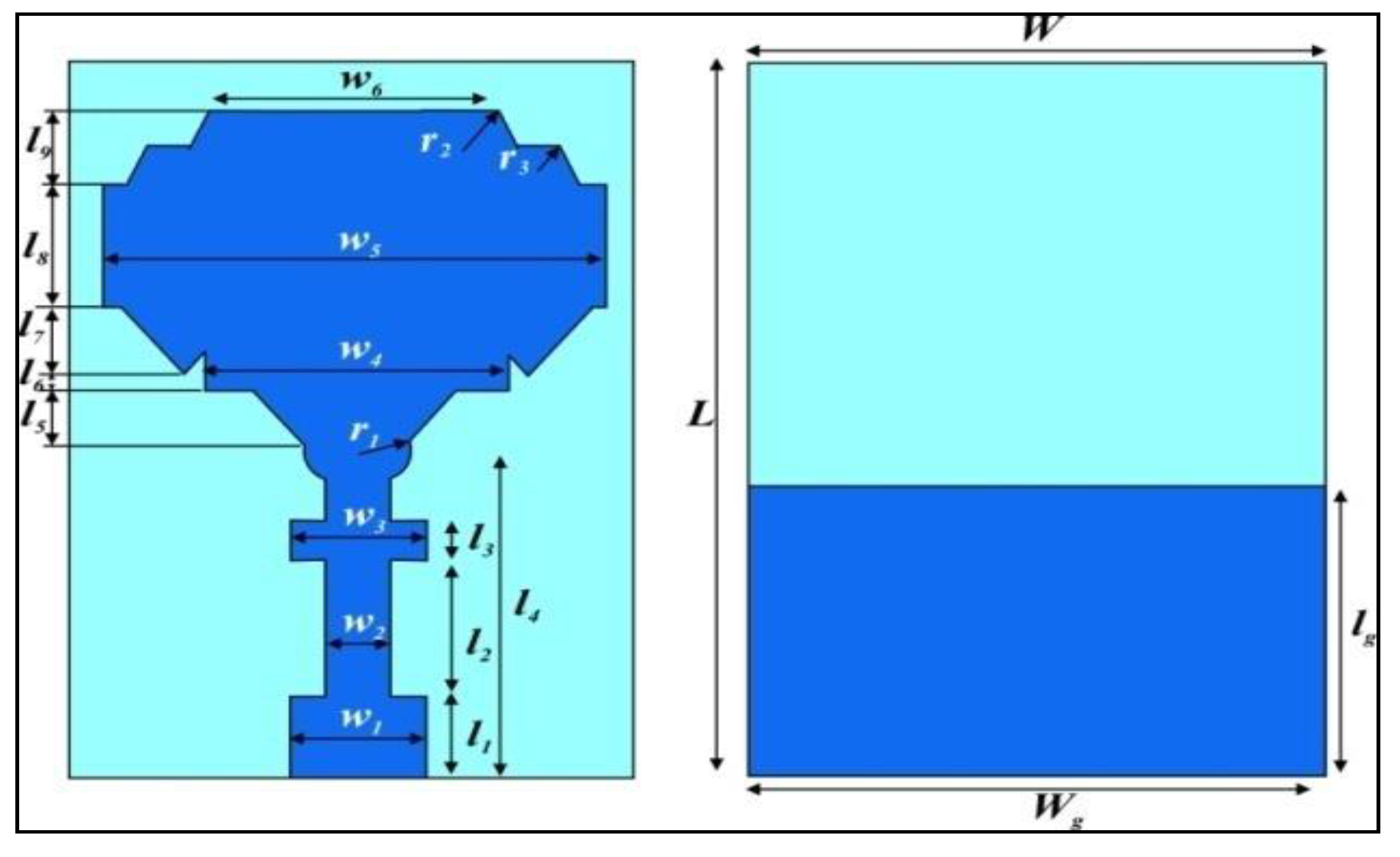
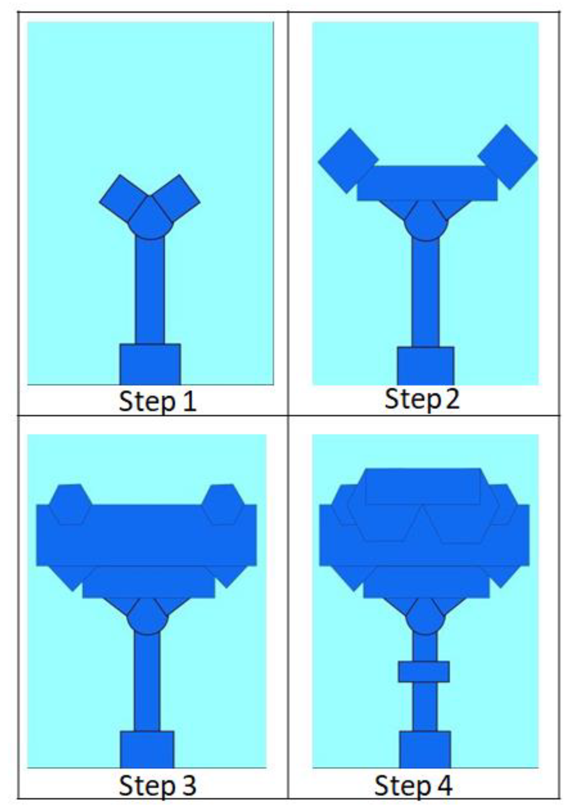
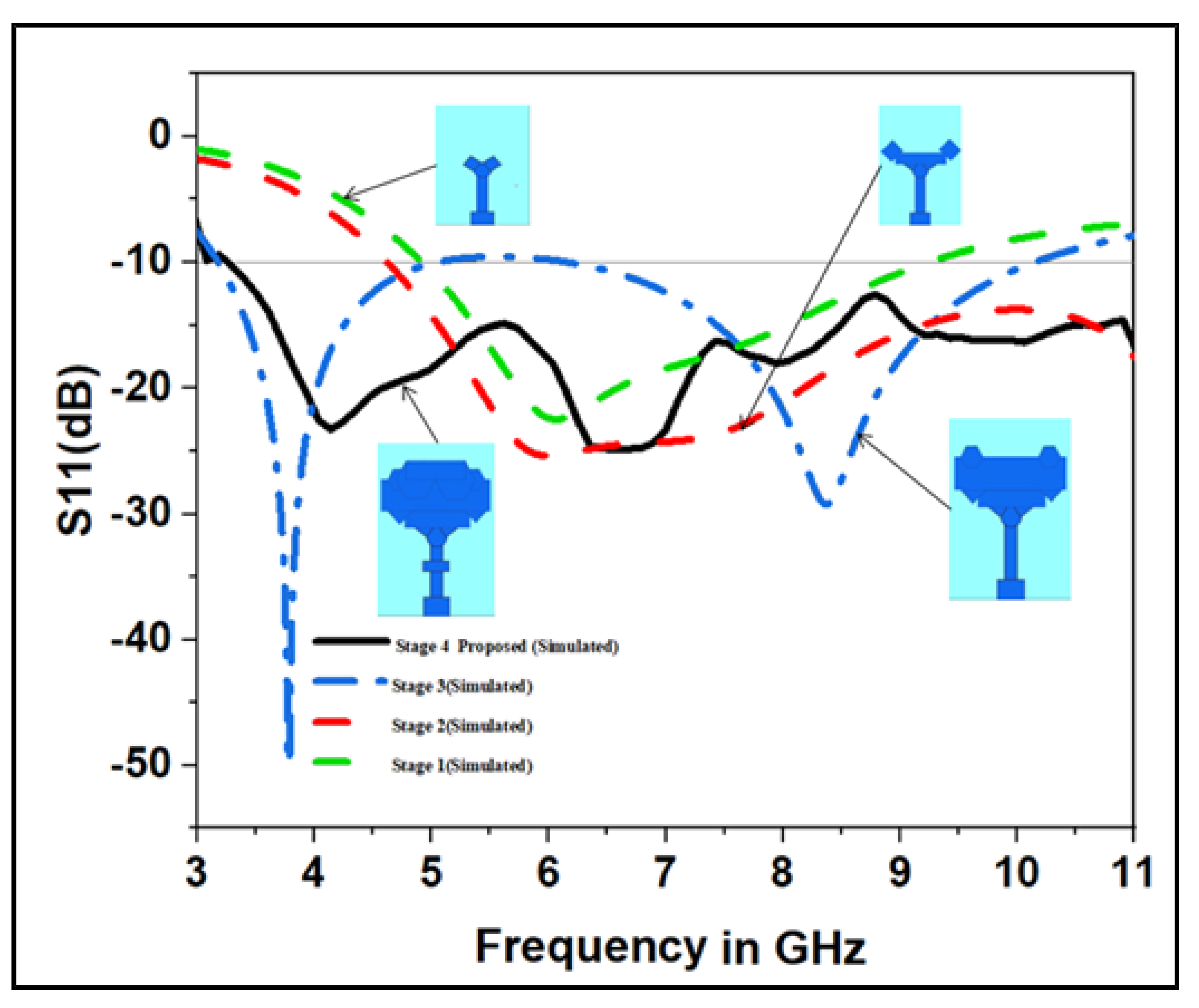
2.1. Unit Cell Design

The unit cell of the proposed antenna consisted of a partial ground plane and an antenna radiator that was designed in four steps, where different geometrical shapes (square, rectangular, hexagonal, and V-shaped patch) were used, finally leading to the particular form shown in Figure 1. The computer simulation tool CST Microwave Studio was used for the design, analysis, and optimization process of the proposed antenna. The left half of Figure 1 illustrates the front view (radiating element) of the unit cell, whereas the right half illustrates the rear view (ground plane) of the unit cell. The optimized geometrical dimensions of the proposed antenna are listed in Table 1.
A 50 Ω microstrip line fed the single unit cell with a hexagonally shaped radiator with dimensions of 10 mm × 18 mm. The FR4 substrate had a permittivity value of 4.3 and a loss tangent of 0.02. One side of the substrate had a 0.035 mm thick ground plane. The design of the partial ground plane played a key role in achieving UWB performance. The use of a partial plane in the substrate reduced the storage of energy, which caused a decrease in the quality factor and eventually resulted in an improved bandwidth. Tapered feed lines of 9 × 3 mm2 were used to increase the current flooding near the radiator and achieve the required impedance.
Various stages of evolution were carried out in order to arrive at the final design of the single unit-cell antenna. At every stage, the S parameter of the simulated antennal cell was evaluated and suitable modifications were incorporated into the unit cell design for improving the S parameter. The final design of the unit-cell antenna was achieved over four stages of evolution, as shown in Figure 2. The simulated S parameters during the evolution stages are displayed in Figure 3. The antenna designed in Step 1 consisted of a low-profile, compact-sized microstrip line-fed V-shaped patch. (Refer to Step 1 in Figure 2). This antenna, however, had a poor impedance bandwidth, as seen in the green-colored curve in Figure 3. In evolution Step 2, a rectangle radiator and two rotated square-shaped radiators were integrated into a microstrip-fed V-shaped radiator to increase the impedance bandwidth, as shown in Step 2 of Figure 2. In this modification, the upper UWB frequencies were covered, but the lower UWB frequencies were not covered well. The hexagonal-form radiator concept is an intelligent solution for compact UWB MIMO antennas. In Step 3, we added two hexagonally shaped radiators along with another rectangular radiator to increase the impedance bandwidth. The resulting impedance bandwidth curve is shown in blue color. It can be seen from the curve that the impedance bandwidth improved. The final evolution was carried out for further improvement by adding a rectangular patch at the top of the structure, as shown in Step 4 of Figure 2. The corresponding curve is shown in black color in Figure 3. Pictures of the fabricated unit-cell antenna, along with a scale, are displayed in Figure 4.

2.2. Monopole UWB MIMO Antenna

The ultra-wideband MIMO monopole antenna can be made using four unit-cell antennas. The unit-cell structure described in the above section was used to develop the UWB MIMO antenna. Four unit-cell antennas were mounted at the four corners of the substrate to form the proposed antenna. The mutual coupling and isolation are important parameters that have significant effects for individuality between the unit cells. In order to boost the performance of the MIMO antenna, it was necessary to achieve adequate isolation. For this reason, the four unit cells were arranged orthogonally. The front and back views of the proposed MIMO antenna structure are illustrated in Figure 5. Better performance of the MIMO antenna can be obtained by restricting the scattering parameters below −15 dB.
The front and back views of the fabricated MIMO antenna are shown in Figure 6. The overall size of the four-port antenna was 28 × 28 × 1.6 mm3. Figure 7 shows the unit-cell antenna scattering parameter (S11) over the target bandwidth. It can be seen that the value of S11 is below −10 dB over the entire frequency range from 3.1 to 10.6 GHz.

3. Results and Discussion

The fabricated prototype of the antenna was experimentally evaluated and validated by a comparison of the simulated and measured results. Measurements to determine the antenna’s MIMO/Diversity parameters were conducted using an Anritsu MS2703 Vector Network Analyzer, shown in Figure 8. The diversity parameter measurement and radiation pattern measurement were conducted using a setup in an anechoic chamber, as shown in Figure 9. The performance comparison of the proposed design with the existing designs is also presented.
S-parameters can be used to calculate various parameters of MIMO systems that enable a quantitative comparison of the MIMO systems. These parameters include envelope correlation coefficients (ECC), diversity gains (DG), channel capacity losses (CCL), and the total active reflection coefficient (TARC). CST Microwave Studio software was used to simulate and analyze the antenna’s radiation characteristics.

3.1. Mutual Coupling

The Ultra-wideband MIMO monopole antenna was made by arranging multiple unit-cell antennas of a similar shape. When multiple unit-cell antennas are integrated into a small substrate to form a UWB MIMO antenna, stronger mutual coupling between cells leads to antenna impedance mismatching, which ultimately reduces the channel capacity. For a given unit-cell antenna i, the mutual coupling due to the other cell j, with (ij), can be obtained in terms of the Sij parameter. The MIMO antenna’s orthogonal arrangement reduced the mutual coupling and overall size. The UWB MIMO monopole antenna design should have a mutual coupling of less than −20 dB for optimal performance.
Figure 10 shows the measured and simulated results for the isolation of the proposed UWB MIMO monopole antenna. It is clear from the figure that the proposed UWB-MIMO antennal system provides a high isolation and a mutual coupling of less than −20 dB over the frequency range from 3.1 to 10.6 GHz. Better performance of the proposed antenna in terms of the isolation and mutual coupling between antennal elements was achieved due to the use of the reduced ground plane and tapered feed in the design.

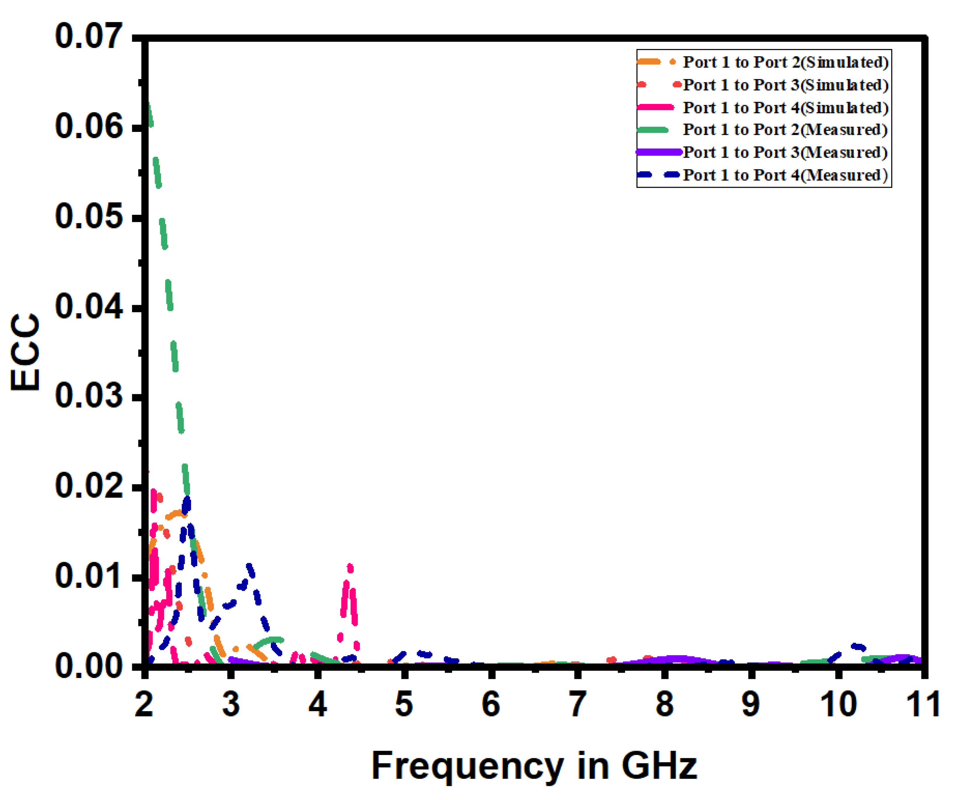
3.2. Envelope Correlation Coefficient (ECC)

A MIMO antenna’s essential diversity parameter is the correlation between the radiating elements. The envelope correlation coefficient reflects how the antennal elements are independent of each other. It measures the similarity between the performances of the antennas from a radiation pattern point of view. Ideally, the radiation patterns of two or more antennas should be entirely independent of each other. The value of ECC can be estimated by using 3D radiation patterns. This value should be 0 in the ideal case, and it should not exceed 0.5 in any practical case. Lower values of ECC mean that the two antennas are well isolated. Although it is difficult to estimate the ECC value, it can still be computed using the S parameters. The envelope correlation coefficient is determined by replacing the S parameters in Equation (1) [36,37].
E C C i j = S ii *   S ij + S ji * S jj 2 1 S ii 2   S ij 2   1 S jj 2   S ji 2  
Here, i and j are the port numbers. Looking at Figure 11, we find that the ECC is much less than 0.001 between all the ports, which is closely equal to the ideal value of the envelope correlation coefficient.

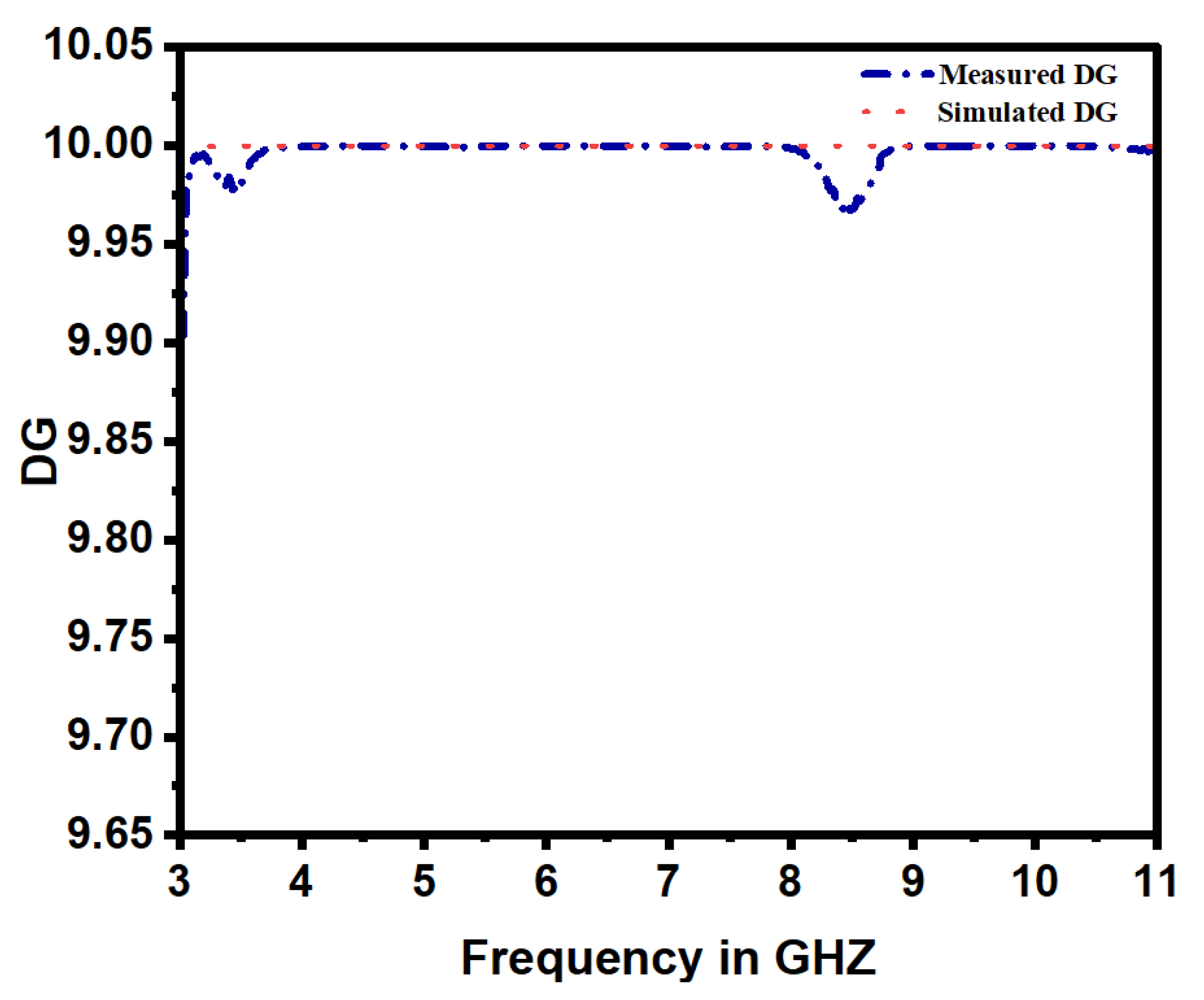
3.3. Diversity Gain (DG)

The UWB MIMO antenna’s diversity gains must be the pinnacle of making the wireless communication device more authentic and delivering better efficiency. The ideal value is 10 dB. The value for the diversity gain can be determined for the given antenna using the formula in Equation (2) [37].
DG = 10 1 | E C C i j | 2
The measured and simulated DG1,2 of the proposed antenna are shown in Figure 12. We can confirm from this Figure that the maximum gain in diversity was 9.999 dB. We also noticed that the value of the diversity gain was very similar for the simulated and measured cases.

3.4. Total Active Reflection Coefficient (TARC)

The ratio between the squared value of the reflected power and its incident power at the port is called total active reflection coefficient (TARC). It relates to the coupling between ports. For an N port antenna, the TARC ratio can be presented as in Equation (3) [38,39]:
Γ a t = i = 1 N y i 2 i = 1 N x i 2
where x i represents incident signals and y i represents reflected signals. The scattering matrix of a 2 × 2 antennal array can be patterned as:
y 1 y 2 = s 11 s 12 s 21 s 22 x 1 x 2
The minimum value of TARC is 0, which indicates that all incident power is radiated, whereas the maximum value is 1, which indicates that all the incident power is reflected. The phase of any excitation signal is unpredictable in the MIMO antenna. Before the signal enters the receiver, the propagation environment allows different signal phase selection. The MIMO signal, also called a random phase, is independent and distributed similarly. Gaussian values are obtained from the difference of Gaussian random variables; reflected signals are expressed as [40,41]. The TARC of the antenna was calculated at a random phase of 0° and is plotted in Figure 13.
y 1 = S 11 x 1 + S 12 x 2   = S 11   x 0   e j θ 1 + S 12   x 0   e j θ 2   = x 1 S 11   + S 12   e j θ
y 2 = S 21 x 1 + S 22 x 2   = S 21   x 0   e j θ 1 + S 22   x 0   e j θ 2   = x 1 S 21   + S 22 e j θ
Therefore, the TARC is described as follows:
Γ a t = ( x 1 S 11 + S 12 e j θ 2 + x 1 S 21 + S 22 e j θ 2 2 x 1 2
Γ a t = ( S 11 + S 12 e j θ 2 + S 21 + S 22 e j θ 2 2
To achieve the best operation of MIMO antennas, the TARC value must be less than −10 dB. Figure 13 indicates that the proposed design agrees well with the default TARC norm values. Thus, from Figure 11 and Figure 13, it can be claimed that the antenna was competent for diversity reception/transmission in the MIMO channels.

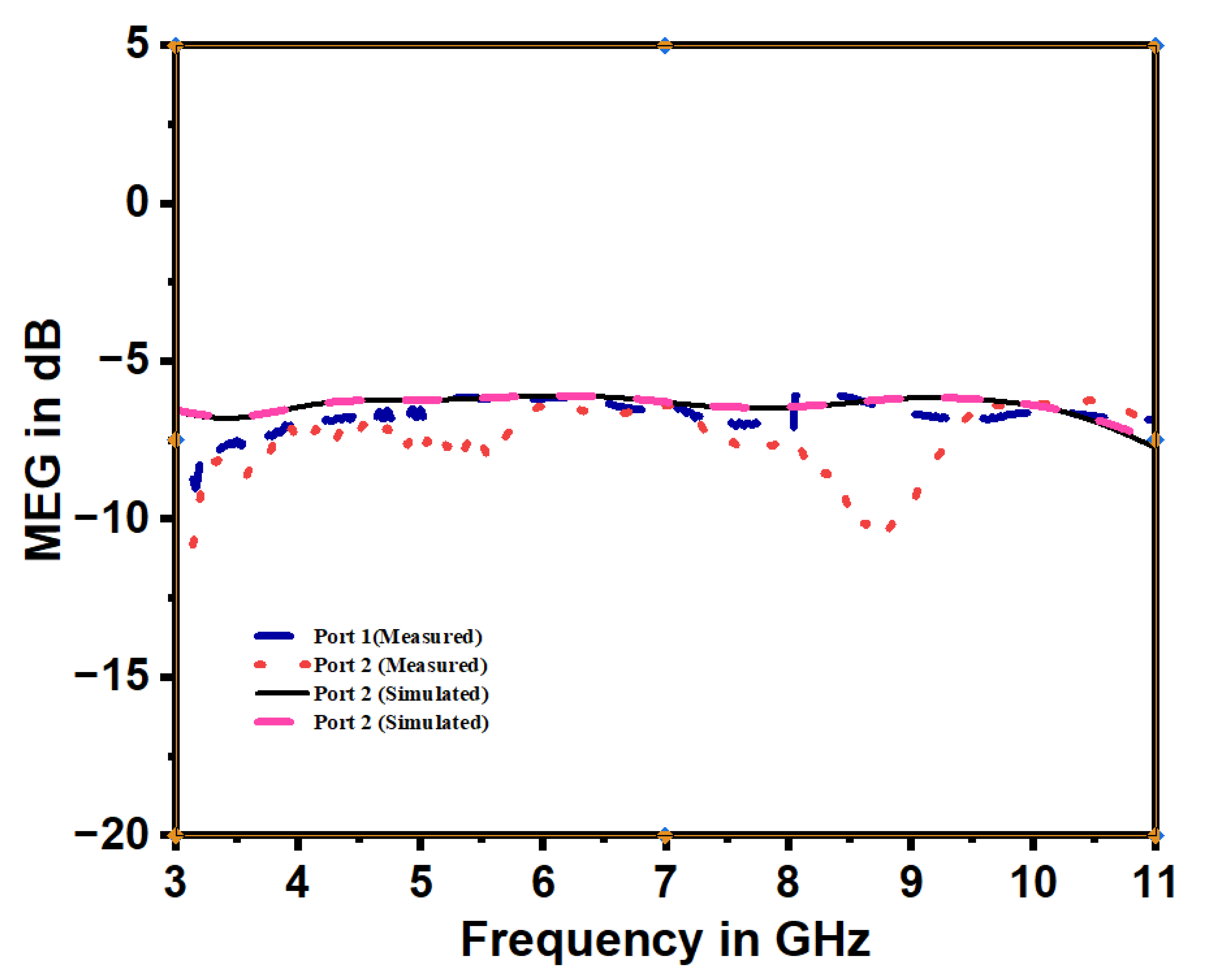
3.5. Mean Effective Gain (MEG)

The mean effective gain of the unknown antenna related to the reference antenna averaged over the route can be compared by the mean power level of the unknown antenna with that of the reference antenna [42].
The MEG value for the MIMO antenna system was determined using the following relationship [43].
MEG i = 0.5 1 j = 1 N | S i j | 2 ,     i = 1 , 2
The ratios of the mean effective gains (MEGi/MEGj) were calculated to quantify the power imbalance of the antennal elements. To guarantee a good channel characteristic, the signal received from the antennas should satisfy the following criteria [24].
  MEG i MEG j 1
The MEG plot of the proposed multiple-in and multiple-out antenna is depicted in Figure 14. It shows that the MEG curves of different ports are the same. It indicates a better overall performance of the proposed radiator array.

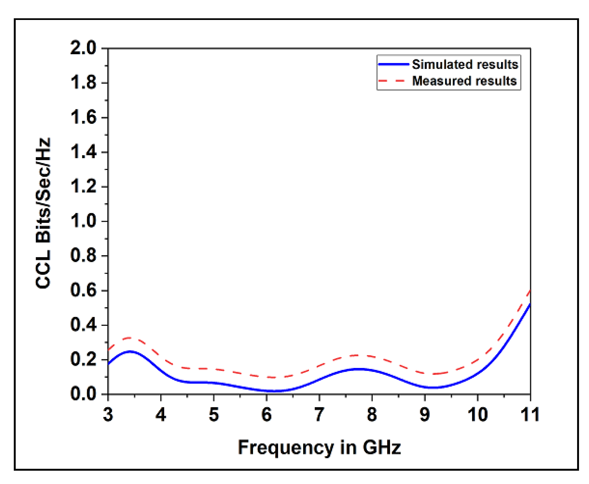
3.6. Channel Capacity Loss (CCL)

The correlation between the elements in MIMO channel systems produces a capacity loss. It can be calculated as follows [44].
C loss = l o g   2   d e t Ψ R
ψ R = ψ 11 ψ 12 ψ 21 ψ 22
ψ 11 = 1 S 11 2 + S 12 2
ψ 22 = 1 S 22 2 + S 21 2
ψ 12 = S 11 * S 12 + S 21 * S 22
ψ 21 = S 22 * S 21 + S 12 * S 11  
It is desirable to have a CCL value that is less than 0.4 bits/s/Hz. The proposed radiator’s CCL values for the UWB spectrum are shown in Figure 15 as a simulation and measurement. From the diagram, it can be seen that the proposed design achieved the recommended MIMO antenna CCL value over the operational frequency spectrum.

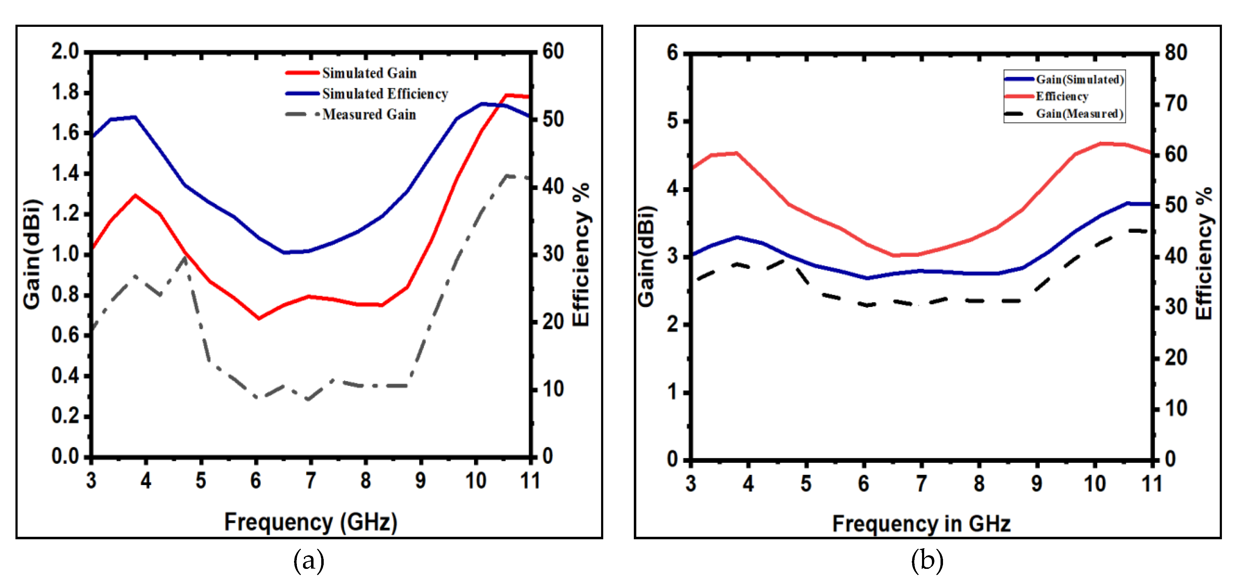
3.7. Gain and Percentage Efficiency

The gain and efficiency curves of the proposed single-element antenna are displayed in Figure 16a. The proposed single antenna design provided a gain of around 1.8 dBi and an efficiency of around 55%. Similarly, the gain and efficiency curves of the proposed MIMO antenna are displayed in Figure 16b. The proposed MIMO design demonstrated a simulated peak gain of 3.8 dBi while the measured peak gain was 3.0 dBi for the MIMO antenna. Similarly, the peak antenna efficiency was about 65%.

3.8. Radiation Patterns

The radiation patterns of the simulated and measured results for the proposed monopole UWB MIMO antenna in the x–z plane (H-plane) and y–z plane (E-plane) at 5.5 GHz frequency are shown in Figure 17 for each port. Orthogonal polarization is achieved when two linearly polarized waves are perpendicular to each other. The waves do not interact with each other, as they are orthogonal to each other, and therefore they are well isolated. The isolation between multiple antennas can be improved by placing the antennas in such a manner that the antenna’s polarization is orthogonal. According to the results, it was found that the simulated radiation patterns were in good agreement with the measured one. The proposed antenna exhibited an omnidirectional radiation pattern. The measured results offered good coverage for UWB communications.
Table 2 presents a quantitative comparison of the proposed antenna design with the antenna designs reported in the literature. The comparison was made on the basis of different types of structures and parameters, such as the design method, the number of ports, the size of antenna, the isolation, TARC, ECC, CCL, gain, and the operating frequency range.
In this comparison, it was observed that the proposed antenna was the most compact, as its size in terms of area was 28 × 28 = 784 mm2, which was the smallest among all other antennas. The proposed antenna provided better isolation than that provided by the other antennas of a comparable size. Further, the design achieved promising results in terms of a CCL value less than 0.4 bits/s/Hz, a TARC value less than −10 dB, and an ECC value less than 0.001.

4. Conclusions

A design of a compact four-port UWB MIMO antenna with the overall dimensions of 28 mm × 28 mm × 1.6 mm is presented in this paper. Polarization diversity, an orthogonal arrangement, and a tapered feed were employed in the MIMO antenna to achieve a higher isolation. The proposed antenna operated in the entire UWB band (3.1–10.6 GHz) with a high isolation. The antenna had an average gain of 3.0 dBi. The diversity performance of the proposed antenna was good, with an ECC value less than 0.001, a DG value greater than 9.90, a TARC value less than −10 dB, and an isolation greater than 20 dB. The measured values of return loss, isolation, and the radiation pattern agree with the simulated ones. In summary, the proposed antenna is a promising candidate for UWB MIMO wireless diversity applications. One challenge these antennas face is electromagnetic interference between UWB and licensed frequency bands. Future designs should aim at the construction of an antenna with notched-band features to mitigate this issue.

Author Contributions

Conceptualization, S.K., L.B. and M.M.; data curation, S.K.; formal analysis, S.K.; investigation, S.K.; methodology, S.K., L.B. and M.M.; software, S.K., L.B. and M.M.; supervision, L.B.; writing—original draft, S.K.; writing—review and editing, L.B. and M.M. All authors have read and agreed to the published version of the manuscript.

Funding

This work was supported by the project SP2022/60 Applied Research in the Area of Machines and Process Control, supported by the Ministry of Education, Youth and Sports, Czech Republic.

Data Availability Statement

The data presented in this study are available through email upon request to the corresponding author.

Conflicts of Interest

The authors declare no conflict of interest.

References

  1. Chen, Z.N.; Ammann, M.J.; Qing, X.; Wu, X.H.; See, T.S.; Cai, A. Planar antennas. IEEE Microw. Mag. 2006, 7, 63–73. [Google Scholar] [CrossRef]
  2. Zhou, G.; Deng, R.; Zhou, X.; Long, S.; Li, W.; Lin, G.; Li, X. Gaussian Inflection Point Selection for LiDAR Hidden Echo Signal Decomposition. IEEE Geosci. Remote Sens. Lett. 2021, 19, 1–5. [Google Scholar] [CrossRef]
  3. Kong, H.; Lu, L.; Yu, J.; Chen, Y.; Tang, F. Continuous Authentication Through Finger Gesture Interaction for Smart Homes Using WiFi. IEEE Trans. Mob. Comput. 2021, 20, 3148–3162. [Google Scholar] [CrossRef]
  4. Liu, G. Data Collection in MI-Assisted Wireless Powered Underground Sensor Networks: Directions, Recent Advances, and Challenges. IEEE Commun. Mag. 2021, 59, 132–138. [Google Scholar] [CrossRef]
  5. Schantz, H.G. A brief history of UWB antennas. IEEE Aerosp. Electron. Syst. Mag. 2004, 19, 22–26. [Google Scholar] [CrossRef]
  6. Zhou, G.; Li, W.; Zhou, X.; Tan, Y.; Lin, G.; Li, X.; Deng, R. An innovative echo detection system with STM32 gated and PMT adjustable gain for airborne LiDAR. Int. J. Remote Sens. 2021, 42, 9187–9211. [Google Scholar] [CrossRef]
  7. Zhou, G.; Long, S.; Xu, J.; Zhou, X.; Song, B.; Deng, R.; Wang, C. Comparison Analysis of Five Waveform Decomposition Algorithms for the Airborne LiDAR Echo Signal. IEEE J. Sel. Top. Appl. Earth Obs. Remote Sens. 2021, 14, 7869–7880. [Google Scholar] [CrossRef]
  8. Wu, H.; Jin, S.; Yue, W. Pricing Policy for a Dynamic Spectrum Allocation Scheme with Batch Requests and Impatient Packets in Cognitive Radio Networks. J. Syst. Sci. Syst. Eng. 2022, 31, 133–149. [Google Scholar] [CrossRef]
  9. Federal Communications Commission, Revision of Part 15 of the Commission’s Rules Regarding Ultra-Wideband Transmission Systems. First Report and Order, pp.FCC-02. Available online: https://www.fcc.gov/document/revision-part-15-commissions-rules-regarding-ultra-wideband-7 (accessed on 1 August 2022).
  10. Khan, M.S.; Capobianco, A.-D.; Asif, S.M.; Anagnostou, D.E.; Shubair, R.M.; Braaten, B.D. A Compact CSRR-Enabled UWB Diversity Antenna. IEEE Antennas Wirel. Propag. Lett. 2016, 16, 808–812. [Google Scholar] [CrossRef]
  11. Chandel, R.; Gautam, A.K.; Rambabu, K. Design and Packaging of an Eye-Shaped Multiple-Input–Multiple-Output Antenna with High Isolation for Wireless UWB Applications. IEEE Trans. Compon. Packag. Manuf. Technol. 2018, 8, 635–642. [Google Scholar] [CrossRef]
  12. Saxena, S.; Kanaujia, B.; Dwari, S.; Kumar, S.; Tiwari, R. MIMO antenna with built-in circular shaped isolator for sub-6 GHz 5G applications. Electron. Lett. 2018, 54, 478–480. [Google Scholar] [CrossRef]
  13. Dikmen, C.M.; Cimen, S.; Cakir, G. Planar Octagonal-Shaped UWB Antenna with Reduced Radar Cross Section. IEEE Trans. Antennas Propag. 2014, 62, 2946–2953. [Google Scholar] [CrossRef]
  14. Gopikrishna, M.; Das Krishna, D.; Anandan, C.K.; Mohanan, P.; Vasudevan, K. Design of a Compact Semi-Elliptic Monopole Slot Antenna for UWB Systems. IEEE Trans. Antennas Propag. 2009, 57, 1834–1837. [Google Scholar] [CrossRef]
  15. Saad, A.A.R.; Mohamed, H.A. Conceptual design of a compact four-element UWB MIMO slot antenna array. IET Microw. Antennas Propag. 2019, 13, 208–215. [Google Scholar] [CrossRef]
  16. Tang, Z.; Wu, X.; Zhan, J.; Hu, S.; Xi, Z.; Liu, Y. Compact UWB-MIMO Antenna With High Isolation and Triple Band-Notched Characteristics. IEEE Access 2019, 7, 19856–19865. [Google Scholar] [CrossRef]
  17. Yang, L.; Xu, M.; Li, C. Four-Element MIMO Antenna System for UWB Applications. Radioengineering 2019, 28, 60–67. [Google Scholar] [CrossRef]
  18. Koohestani, M.; Moreira, A.A.; Skrivervik, A.K. A Novel Compact CPW-Fed Polarization Diversity Ultrawideband Antenna. IEEE Antennas Wirel. Propag. Lett. 2014, 13, 563–566. [Google Scholar] [CrossRef]
  19. Yu, J.-F.; Liu, X.L.; Shi, X.-W.; Wang, Z. A compact four-element UWB MIMO antenna with QSCA implementation. Prog. Electromagn. Res. Lett. 2014, 50, 103–109. [Google Scholar] [CrossRef]
  20. Wang, L.; Du, Z.; Yang, H.; Ma, R.; Zhao, Y.; Cui, X.; Xi, X. Compact UWB MIMO Antenna with High Isolation Using Fence-Type Decoupling Structure. IEEE Antennas Wirel. Propag. Lett. 2019, 18, 1641–1645. [Google Scholar] [CrossRef]
  21. Wang, F.; Duan, Z.; Li, S.; Wang, Z.L.; Gong, Y.B. Compact UWB MIMO antenna with metamaterial-inspired isolator. Prog. Electromagn. Res. C 2018, 84, 61–74. [Google Scholar]
  22. Srivastava, G.; Dwari, S.; Kanuijia, B.K. A compact 4 × 4 ultrawideband(UWB) band notched MIMO antenna. In Proceedings of the 2014 IEEE International Microwave and RF Conference (IMaRC), Bangalore, India, 15–17 December 2014; IEEE: Piscataway, NJ, USA, 2014; pp. 198–200. [Google Scholar] [CrossRef]
  23. Mao, C.-X.; Chu, Q.-X. Compact Coradiator UWB-MIMO Antenna with Dual Polarization. IEEE Trans. Antennas Propag. 2014, 62, 4474–4480. [Google Scholar] [CrossRef]
  24. Zhu, J.; Li, S.; Feng, B.; Deng, L.; Yin, S. Compact dual-polarized UWB quasi-self-complementary MIMO/diversity antenna with band-rejection capability. IEEE Antennas Wirel. Propag. Lett. 2015, 15, 905–908. [Google Scholar] [CrossRef]
  25. Wu, Y.; Ding, K.; Zhang, B.; Li, J.; Wu, D.; Wang, K. Design of a Compact UWB MIMO Antenna without Decoupling Structure. Int. J. Antennas Propag. 2018, 2018, 9685029. [Google Scholar] [CrossRef]
  26. Behdad, N.; Li, M.; Yusuf, Y. A Very Low-Profile, Omnidirectional, Ultrawideband Antenna. IEEE Antennas Wirel. Propag. Lett. 2013, 12, 280–283. [Google Scholar] [CrossRef]
  27. Altaf, A.; Iqbal, A.; Smida, A.; Smida, J.; Althuwayb, A.A.; Hassan Kiani, S.; Alibakhshikenari, M.; Falcone, F.; Limiti, E. Iso-lation Improvement in UWB-MIMO Antenna System Using Slotted Stub. Electronics 2020, 9, 1582. [Google Scholar] [CrossRef]
  28. Liu, X.-L.; Wang, Z.-D.; Yin, Y.-Z.; Ren, J.; Wu, J.-J. A Compact Ultrawideband MIMO Antenna Using QSCA for High Isolation. IEEE Antennas Wirel. Propag. Lett. 2014, 13, 1497–1500. [Google Scholar] [CrossRef]
  29. Tripathi, S.; Mohan, A.; Yadav, S. A Compact Koch Fractal UWB MIMO Antenna With WLAN Band-Rejection. IEEE Antennas Wirel. Propag. Lett. 2015, 14, 1565–1568. [Google Scholar] [CrossRef]
  30. Althuwayb, A.A. Low-Interacted Multiple Antenna Systems Based on Metasurface-Inspired Isolation Approach for MIMO Applications. Arab. J. Sci. Eng. 2022, 47, 2629–2638. [Google Scholar] [CrossRef]
  31. Alibakhshikenari, M.; Babaeian, F.; Virdee, B.S.; Aïssa, S.; Azpilicueta, L.; See, C.H.; Althuwayb, A.A.; Huynen, I.; Abd-Alhameed, R.A.; Falcone, F.; et al. A comprehensive survey on “Various decoupling mechanisms with fo-cus on metamaterial and metasurface principles applicable to SAR and MIMO antenna systems”. IEEE Access 2020, 8, 192965–193004. [Google Scholar] [CrossRef]
  32. Althuwayb, A.A. Enhanced radiation gain and efficiency of a metamaterial-inspired wideband microstrip antenna using substrate integrated waveguide technology for sub-6 GHz wireless communication systems. Microw. Opt. Technol. Lett. 2021, 63, 1892–1898. [Google Scholar] [CrossRef]
  33. Alibakhshikenari, M.; Virdee, B.S.; Salekzamankhani, S.; Aïssa, S.; See, C.H.; Soin, N.; Fishlock, S.J.; Althuwayb, A.A.; Abd-Alhameed, R.; Huynen, I.; et al. High-isolation antenna array using SIW and realized with a graphene layer for sub-terahertz wireless applications. Sci. Rep. 2021, 11, 10218. [Google Scholar] [CrossRef] [PubMed]
  34. Jamshed, M.A.; Ur-Rehman, M.; Frnda, J.; Althuwayb, A.A.; Nauman, A.; Cengiz, K. Dual Band and Dual Diversity Four-Element MIMO Dipole for 5G Handsets. Sensors 2021, 21, 767. [Google Scholar] [CrossRef] [PubMed]
  35. Naktong, W.; Ruengwaree, A. Four-port rectangular monopole antenna for UWB-MIMO applications. Prog. Electromagn. Res. B 2020, 87, 19–38. [Google Scholar] [CrossRef]
  36. CST Microwave Studio Suite 2018. Available online: www.cst.com (accessed on 1 August 2022).
  37. Khalid, M.; Naqvi, S.I.; Hussain, N.; Rahman, M.; Fawad; Mirjavadi, S.S.; Khan, M.J.; Amin, Y. 4-Port MIMO Antenna with Defected Ground Structure for 5G Millimeter Wave Applications. Electronics 2020, 9, 71. [Google Scholar] [CrossRef]
  38. Chae, S.H.; Kawk, W.I.; Park, S.-O.; Lee, K. Analysis of mutual coupling in MIMO antenna array by TARC calculation. In Proceedings of the 2006 Asia-Pacific Microwave Conference, Yokohama, Japan, 12–15 December 2006; IEEE: Piscataway, NJ, USA, 2006; pp. 2090–2093. [Google Scholar] [CrossRef]
  39. Chae, S.H.; Oh, S.-K.; Park, S.-O. Analysis of Mutual Coupling, Correlations, and TARC in WiBro MIMO Array Antenna. IEEE Antennas Wirel. Propag. Lett. 2007, 6, 122–125. [Google Scholar] [CrossRef]
  40. Amin, F.; Saleem, R.; Shabbir, T.; Rehman, S.U.; Bilal, M.; Shafique, M.F. A Compact Quad-Element UWB-MIMO Antenna System with Parasitic Decoupling Mechanism. Appl. Sci. 2019, 9, 2371. [Google Scholar] [CrossRef]
  41. Anitha, R.; Vinesh, P.V.; Prakash, K.C.; Mohanan, P.; Vasudevan, K. A Compact Quad Element Slotted Ground Wideband Antenna for MIMO Applications. IEEE Trans. Antennas Propag. 2016, 64, 4550–4553. [Google Scholar] [CrossRef]
  42. Taga, T. Analysis for mean effective gain of mobile antennas in land mobile radio environments. IEEE Trans. Veh. Technol. 1990, 39, 117–131. [Google Scholar] [CrossRef]
  43. Nasir, J.; Jamaluddin, M.H.; Khan, A.A.; Kamarudin, M.R.; Leow, C.Y.; Owais, O. Throughput Measurement of a Dual-Band MIMO Rectangular Dielectric Resonator Antenna for LTE Applications. Sensors 2017, 17, 148. [Google Scholar] [CrossRef] [Green Version]
  44. Ali, W.A.; Ibrahim, A.A. A compact double-sided MIMO antenna with an improved isolation for UWB applications. AEU Int. J. Electron. Commun. 2017, 82, 7–13. [Google Scholar] [CrossRef]
  45. Ibrahim, A.A.; Abdalla, M.A.; Hu, Z. Design of a compact mimo antenna with asymmetric coplanar strip-fed for UWB applications. Microw. Opt. Technol. Lett. 2017, 59, 31–36. [Google Scholar] [CrossRef]
  46. Malviya, L.; Panigrahi, R.K.; Kartikeyan, M.V. Four Element Planar MIMO Antenna Design for Long-Term Evolution Operation. IETE J. Res. 2018, 64, 367–373. [Google Scholar] [CrossRef]
  47. Kolangiammal, S.; Vairavel, G. Compact Planar Monopole UWB MIMO Antenna for Diversity Applications. In Advances in Smart System Technologies; Springer: Singapore, 2021; pp. 281–291. [Google Scholar] [CrossRef]
Figure 1. Front and rear views of unit-cell antenna.
Electronics 11 03087 g001
Figure 2. Evolution of monopole UWB unit-cell antenna.
Electronics 11 03087 g002
Figure 3. Simulated S parameter S11 during evolution stages.
Electronics 11 03087 g003
Figure 4. Fabricated unit-cell antenna.
Electronics 11 03087 g004
Figure 5. Front and rear view of MIMO antenna structure.
Electronics 11 03087 g005
Figure 6. Fabricated UWB MIMO antenna.
Electronics 11 03087 g006
Figure 7. Simulated and measured S11 parameters of the monopole UWB unit-cell antenna.
Electronics 11 03087 g007
Figure 8. Anritsu MS2703 Vector Network Analyzer used to measure MIMO parameters.
Electronics 11 03087 g008
Figure 9. MIMO antenna experimental measurement setup.
Electronics 11 03087 g009
Figure 10. Simulated and measured isolation of monopole UWB MIMO antenna.
Electronics 11 03087 g010
Figure 11. Simulated and measured ECC of monopole UWB MIMO antenna.
Electronics 11 03087 g011
Figure 12. Measured and simulated DG1,2 of monopole UWB MIMO antenna.
Electronics 11 03087 g012
Figure 13. TARC of the monopole MIMO UWB antenna.
Electronics 11 03087 g013
Figure 14. Simulated and measured MEG of proposed antenna.
Electronics 11 03087 g014
Figure 15. CCL of the monopole MIMO ultra-wideband antenna.
Electronics 11 03087 g015
Figure 16. (a) Gain and efficiency of proposed single-element antenna. (b) Gain and efficiency of the monopole MIMO UWB antenna.
Electronics 11 03087 g016
Figure 17. The radiation patterns of simulation and measurement results of E-plane and H-plane for all 4 ports: (a) port 1 E-plane; (b) port 1 H-plane; (c) port 2 E-plane; (d) port 2 H-plane; (e) port 3 E-plane; (f) port 3 H-plane; (g) port 4 E-plane; and (h) port 4 H-plane.
Electronics 11 03087 g017aElectronics 11 03087 g017b
Table 1. Geometrical specifications of proposed monopole UWB unit-cell antenna.
Parameterr1r2r3l1l2l3l4l5l6l7l8
Units (mm)10.91.52419121.52.5
Parameterl9lgw1w2w3w4w5w6wgWL
Units (mm)1.3631359.44.5101018
Table 2. Comparison with designs in existing literature.
RefPortsApplied Design MethodSize
(mm2)
Isolation
(dB)
TARC
(dB)
ECCCCL
(bps/Hz)
Gain (dBi)GHz
[15]4AFS miniaturizing technique40 × 40>17-<0.03-52.94–14
[16]4Four-directional staircase-shaped structure39 × 39>22<−10<0.02<0.21.4–4.62.3–13.7
[17]4Decoupling structure70 × 4117<−9<0.012<0.4-3.1–12
[18]2Coplanar-fed 27 × 52≥20-----
[19]4QSCA40 × 40≥20-<0.04−73.85–4.672.9–12.1
[20]2Fence-type decoupling structure35 × 50>25-<0.004--3–11
[22]4Rectangular slots in ground40 × 40>20----3–11.5
[23]4Coradiator40 × 40>10----3–11
[24]4Quasi-self-complementary50 × 50>20-<0.5--3–12
[25]2Circular coupling structure25 × 35>18-<0.005--3.1–11
[45]4Asymmetric coplanar strip-fed40 × 4320−8<0.2<0.3-3.1–10.6
[46]4Phase-reversed and phase-rotated antennal elements 68 × 9810-<0.1--1.66–2.7
[47]4Orthogonal, defected ground structure40 × 40>35-<0.001--3.1–10.6
Proposed4Orthogonal, tapered feed28 × 28>20<−10<0.001< 0.433.1–10.6
Publisher’s Note: MDPI stays neutral with regard to jurisdictional claims in published maps and institutional affiliations.

