


An Embedded Software Development Framework for Internet of Things Devices
by
 , , , and
Camilo Lozoya
1,* ,
,
José Miguel Díaz
2,
César Rodríguez-Esqueda
2,
Claudia Prieto-Resendiz
2 and
Alberto Aguilar-Gonzalez
1,* 1
Tecnologico de Monterrey, School of Engineering and Science, Av. H. Colegio Militar 4700, Chihuahua 31300, Mexico
2
Tecnologico Nacional de Mexico, Av. Tecnologico 2909, Chihuahua 31310, Mexico
*
Authors to whom correspondence should be addressed.
Electronics 2022, 11(24), 4158; https://doi.org/10.3390/electronics11244158
Submission received: 1 November 2022
/
Revised: 24 November 2022
/
Accepted: 5 December 2022
/
Published: 13 December 2022
(This article belongs to the Special Issue Software Engineering for Internet of Things: Architectures, Technologies, and Applications)
Abstract
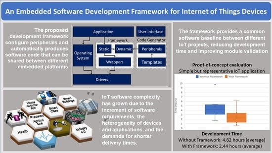
:Internet of things (IoT) devices are mostly ubiquitous in this day and age, and it is hard to imagine a life without them, especially in the productive sectors (industry, agriculture, and automotive) and in our daily life activities (consumer electronics, home automation, and intelligent buildings). The high demand for these devices has created significant competition to provide them at the best price, at the right time, and with the best features. The trend in which these devices have increased their product features has resulted in their embedded software being more complex, leading to extended development and testing times. Consequently, as the types of advanced IoT products keep diversifying, the field maintenance of all the different models deployed grows more complicated. This paper proposes an embedded software development framework for IoT devices independent of the microcontroller architecture, the compiler, and the development environment. This framework allows having a common software baseline between different projects, which shortens the learning curve, development time, and module validation while allowing code reuse for embedded software professionals. A proof-of-concept evaluation is also presented to demonstrate the efficiency and reliability of the obtained embedded software code for a simple but representative IoT application.
1. Introduction
Internet of things (IoT) applications are rapidly expanding due to the growth in interest and investments in the industrial, services, and consumer markets. According to a survey by [1], two-thirds of software developer professionals indicate that their organizations are currently working on the development and deployment of IoT solutions. These solutions enable the interconnection of devices to provide efficiency and intelligence in different contexts [2]. IoT devices are an essential part of our day-to-day lives; they are present in different application areas such as manufacturing, logistics, agriculture, transportation, cities, buildings, homes, and healthcare [3]. An IoT device comprises an embedded system that conducts sensing, actuation, control, and communication tasks within a network infrastructure, managing energy, timing, and space constraints [4]. Analysis, design, implementation, and testing of embedded software for IoT devices have become more complex, while development challenges differ among systems and sectors [5]. The increased use of embedded applications has created new challenges for the software development teams to fulfill user demands. The software complexity in this area has increased due to the constant increment of software requirements, the heterogeneity of devices and applications, the increasingly higher quality standards, and the demands for shorter delivery times.
According to a comprehensive survey of the embedded systems markets worldwide [6], software professionals usually work in teams with an average of 15 to 20 engineers sharing pieces of code and software modules. Further, 56% of developers are working on an upgrade or improvement to an earlier or existing embedded project, while up to 81% of the projects are reusing developed in-house code. The survey also reveals that one-third of the projects in the embedded domain must be completed in 6 months or less; however, more than 60% of the projects are not delivered on time. Therefore, to meet these challenges, software development tools must be in place within organizations to accelerate the software life cycle while ensuring reliable and robust embedded software products for IoT applications [7].
From the perspective of commercial products, most microprocessor and microcontroller vendors provide development tools to reduce the software life cycle and accelerate the deployment of new products or upgrades to existing ones [8,9,10,11,12]. These tools are conformed by proven drivers and code modules integrated into what is known as a development framework with the specific purpose of simplifying the software implementation on embedded devices by providing an abstraction to the hardware using intermediate software elements. However, these frameworks are vendor-specific and only support a small group of microcontroller or microprocessor families, as it is in the vendors’ best interest to lock the client to their ecosystems. On the other hand, low-cost open-source platforms are available to develop rapid prototypes [13,14,15], which simplifies the hardware design, but their development tools [16,17,18] are usually hardware-specific, and software portability is limited. Moreover, these platforms are rarely used for final product deployment.
Software development tools can significantly contribute toward reliable embedded devices [19,20]. Specifically, automatic code generation software can produce skeletal source codes, such as variable declarations, initializations, pre-defined constant values, functions, and types definitions to assist the programmer [21]. Further, code generators preserve similar code structure and coding guidelines in every generated file, facilitating teamwork in a software development organization [22]. Moreover, due to the growing complexity of embedded systems, the need for reusable software components during the development process has become more evident. Specifically, peripheral configuration tools have been a big concern since most development time is consumed in these tasks. In [23,24,25,26], software platforms were presented that allow the designer to configure peripherals, generate code, and build a project to implement specific applications. However, these configuration tools only support a small group of specific microcontrollers, which cannot be extended to other families. Recently, the work developed by [27], proposed a model-based code generator for control systems on an embedded platform to provide software engineers with a solid framework to set up complex control systems. Although the proposed framework generates robust and reliable code based on the specified requirements, the software engineering improvements were not explicitly evaluated.
The software development research community has extensively analyzed and evaluated model-based design with code generator frameworks to reduce development time, improve software quality and produce portable code across different hardware platforms [28,29]. In [30], a model-based solution is implemented to produce GraphQL code for complex cloud computing applications. In [31], RTL (Register Transfer Level) code is automatically generated from UML (Unified Modeling Language) diagrams. Finally, in [32], a model-based testing approach is proposed for user interface web applications. These works focus on providing effective development and testing tools for complex software system solutions; however, software development support for specific microcontroller-based IoT devices is not explicitly addressed since C Language is not on their scope, and it is currently the dominant programming language for embedded devices [6].
This paper presents the design and implementation of a platform-independent development framework that software programmers can use to create embedded projects for IoT devices. Furthermore, a simple but representative IoT application running in two different microcontroller units from different vendors was implemented to validate the proposed framework. This proof-of-concept was conducted on a 32-bit high-performance NXP microcontroller [33] and an 8-bit low-end Microchip microcontroller [34]. The resulting codes were analyzed for each case regarding detected vulnerabilities, code size, execution time, software quality, and development time.
The novel contribution of the proposed framework is to provide a development tool for software professionals in microcontroller-based IoT devices, with similar features offered by the commercial proprietary tools but with the advantage of supporting multiple hardware platforms. The scope of this work considers C Language as the development instrument to implement embedded devices within the IoT application domain. It evaluates the potential benefits of using a single framework for any development project instead of using different specific tools for every microcontroller platform. The research methodology approach for this work started with the analysis of commercial and open-source development tools, then proposed a multiplatform solution, and finally conducted an experimental validation considering development time and software quality as the main evaluated variables. Therefore, the work presented in this paper provides the following specific contributions:
- Conducts a comparative analysis of software development tools features (multiplatform support, automatic peripheral configuration, integrated framework, etc.), based on the functional elements of typical IoT devices, to improve software life cycle.
- Proposes an embedded development framework with a code generator that effectively configures peripherals typically used in IoT devices and automatically produces application code that can be shared between microcontrollers without needing to perform any modifications.
- Validates the efficiency and reliability of the obtained embedded software code compared to code produced without the framework and demonstrates that using the development framework and code generator improves software development time and reduces compiler errors and warnings.
The proposed framework and code generator currently support the following microcontroller platforms:
- MIMXRT1064 (32 bits) from NXP.
- ATMEGA4809 (8 bits) from Atmel.
- MSP430FR6989 (16 bits) from Texas Instrument.
- STM32F334R8 (32 bits) from STMicroelectronics.
More processor units can be added to the framework by building the specific wrappers and static elements according to the guidelines provided by [35].
2. Materials and Methods
An embedded framework is a set of tools used by software developers to build programs for specific applications [36]. The proposed embedded framework aims to assist the developers in configuring and interacting with the microcontrollers’ peripherals seamlessly and independently of the hardware specifics. Embedded systems represent the core of the IoT devices that requires the capability to sense, actuate, and communicate within a network infrastructure. Although IoT devices target different application domains, they share common design challenges to build optimal and cost-effective heterogeneous sensors and actuator networks [37].
Typically, embedded software professionals deal with multiple microcontroller platforms to deliver cost-effective solutions for final product deployment. Therefore, they spend a relevant amount of time analyzing hardware specifications and configuring device peripherals; also, application software reusability across platforms is limited by hardware differences. This section presents a comparative analysis of development tools based on the common requirements for IoT solutions, then the proposed framework and code generator design and implementation details are presented.
2.1. Internet of Things Design and Development Tools
Broadly speaking, an IoT system architecture is composed of three layers: the perception layer, the network layer, and the application layer [38]. The perception or sensing layer is composed of heterogeneous smart and interconnected devices that interact with physical objects to measure, collect, and process their state information while transmitting data into the IoT network [39]. Different communication technologies in the network layer, such as Bluetooth, Zigbee, Wifi, LoRa, LTE, and 5G, are used to transfer data from the devices to a cloud server for further analysis and decision-making that takes place in the application layer [40].
An IoT device comprises a microcontroller, sensors, actuators, a communication transceiver, and a power unit, as depicted in Figure 1. To implement the interface with the sensor, the microcontroller requires the use of an analog-to-digital converter unit (ADC), while the interface with the actuator requires a digital-to-analog unit (DAC), which may include the use of on/off or pulse width modulated (PWM) signals. On the other hand, the interface with the transceiver is typically implemented through serial communication using protocols such as UART (universal asynchronous receiver transmitter), SPI (serial peripheral interface), and I2C (inter-integrated circuit), among others. Examples of implementations of IoT devices for different applications that include these functional elements can be found in [41,42,43,44,45,46,47].
IoT devices typically operate with energy, memory, and computational constraints; therefore, designers must select the adequate microcontroller according to the specific needs of the applications to implement cost-effective solutions. For example, high-performance microcontrollers may be too expensive for basic IoT devices, while low-end microcontrollers may not have enough computational power to support more complex IoT tasks. Additionally, the software developer must consider memory management and energy consumption when implementing the algorithms for IoT devices.
Based on these previous development requirements, Table 1 summarizes the comparative analysis of different software development frameworks conducted to evaluate the following features:
- Hardware platforms: the support of different microcontroller families from different vendors in a single framework assists the developer in focusing more on the application solution rather than on the hardware specifics.
- Peripheral configuration: automatic peripherals configuration simplifies software development and reduces development time.
- Integrated framework: code portability reduces maintenance and promotes the reuse of application code.
- Software solution: software solutions are heterogeneous and may be implemented using either embedded operating systems (OS) or the bare-metal (BM) direct coding approach.
- Targeted applications: the selected development tools provide IoT solutions through embedded devices. However, some tools focus on rapid prototypes while others focus on final user products.
Commercial development tools are vendor-specific to promote their devices, while open-source tools target the development of prototypes, usually for non-professional software developers. Similar approaches found in the literature focus on solving specific problems for IoT applications. The proposed framework provides a platform-independent solution not addressed by commercial tools.
2.2. Software Development Framework Architecture
The proposed software development framework has been designed to allow the migration of an IoT application code into any microcontroller regardless of its family, architecture, and vendor. This allows faster code development, promotes code reusability, and encourages developers to select the adequate microcontroller according to the application requirements.
The framework architecture has been divided into a static element, a dynamic element, and a set of wrappers. Figure 2 shows the architecture of a typical embedded application that uses the framework, which contains the application code, an optional operating system, the framework, and vendor drivers. The architecture allows either the use of an embedded operating system-based implementation or the bare-metal approach.
The application code includes the software modules that do not directly interface with the hardware, but they implement functions and sequential logic required for the system to behave according to the device requirements. Even though this element is represented as a single module, it can contain several modules, each in charge of specific functionality of the IoT device, e.g., network communication, control algorithm, and data acquisition.
The driver element is composed of different code files, which the microcontroller vendors usually provide. These files contain functions, definitions, and data types that can be used to configure and use the different elements in the device, such as general purpose input/output pins and clock sources, among others. The drivers are specific for each microcontroller, and there might be huge differences among them, even if they come from the same vendor.
The three elements that compose the framework are: static, dynamic, and vendor wrappers. The static element’s primary function is to abstract the different operations that can be performed with the microcontroller and its peripherals. The functions defined within this element are generic in order to be able to handle the peripherals without knowing any specific information about the microcontroller being used. This element acts as a bridge between the application module and the other framework elements, and since it contains generic functions, it allows the application code that uses the framework to be used in any microcontroller without requiring any modification. Each peripheral in the microcontroller requires a set of files for the static element (peripheral.h and peripheral.c files), and every microcontroller supported by the framework can reuse this.
The dynamic element contains the files produced by the code generator, which contain the description of how each peripheral used by the application should be configured. The static element consumes these files in order to perform this configuration. The files from this element are application-specific and, therefore, must be one set of files for each peripheral used (peripheral_cfg.c and peripheral_cfg.h files).
The wrappers act as translators between the functions from the static element and the functions contained within the vendor drivers. These files contain generic labels connected with data types and definitions from the vendor drivers. The wrappers also contain functions from the static element that make direct calls to the code contained within the drivers to interact with the peripherals. These labels and functions allow portability in the application module between the different supported microcontrollers because they are defined in the wrappers of every microcontroller. The application module needs to call the functions from the static element using these labels, and the framework will translate and perform the desired operation in the microcontroller. Since the wrappers depend on the microcontroller characteristics, a set of these files (peripheral_wrapper.c and peripheral_wrapper.h files) must be created for each peripheral contained in each microcontroller supported by the framework.
2.3. Supported Peripherals
The peripherals that are currently supported by the framework are the general purpose input/outputs (GPIOs), the analog-to-digital converter (ADC), and the universal asynchronous receiver-transmitter (UART). These represent the essential elements for an IoT device.
The GPIO framework element is formed by the files gpio.c and gpio.h for the static element, gpio_cfg.c and gpio_cfg.h for the dynamic element, and gpio_wrapper.c and gpio_wrapper.h for the wrappers. This module allows the user to configure the following fields on any GPIO contained in a microcontroller: mode (input, output, or used by a microcontroller peripheral), pull resistor (pull-up, pull-down, or none), speed (if supported), output type (open drain or push-pull) and the alternate mode, in the case a peripheral is using the GPIO as another function such as UART or ADC. The framework also allows the user to read and write either to individual pins or the complete port in the microcontroller. The currently supported GPIO functions are shown in Figure 3.
The ADC framework module is formed by the files adc.c and adc.h for the static element, files adc_cfg.c and adc_cfg.h for the dynamic element, and files adc_wrapper.c and adc_wrapper.h for the wrappers. This module allows the user to configure the following fields on any ADC contained in the microcontroller: the clock source, the clock pre-scaler, conversion channel, resolution in bits, number of samples, voltage reference, and the justification (right or left) to store the result in a register. The framework also allows the user to enable or disable the ADC, start a conversion, check the conversion status, and get the conversion result for any ADC in the microcontroller. The supported functions are illustrated in Figure 4.
The UART framework module is formed by the files uart.c and uart.h for the static element, uart_cfg.c and uart_cfg.h for the dynamic element, and uart_wrapper.c and uart_wrapper.h for the wrappers. This module allows the user to configure the following fields on any UART contained within the microcontroller: the clock source, the clock pre-scaler, the baud rate, the number of stop bits, the number of data bits, and the parity (even, odd, or no parity). The framework also allows the user to enable or disable the UART and send or receive data through the polling method. The UART functions are shown in Figure 5.
2.4. Code Generator Implementation
The code generator consists of a desktop application that allows the user to select the project’s microcontroller, configure peripherals, create the dynamics elements, and integrate them into the framework. Figure 6 shows the software modules that implement the code generator.
Each microcontroller model supported by the framework requires an XML (eXtensible Markup Language) file with its hardware specifications. This feature file contains the device’s characteristics, such as manufacturer and model, supported peripherals, and pins’ capabilities. Each pin in the device contains its name, integrated circuit, port, and pin number in the port. It can also contain any alternate function, such as analog-to-digital converters or serial communication. This file is created once and can be used anytime the specific microcontroller is required to develop a solution. First, the XML parser reads the features file and loads the information in the peripherals configuration module. Then, through a user interface, the developer visually configures the peripherals according to the project requirements and stores the selection in the project configuration XML file for further modifications, if required. Finally, the code generator module selects configuration and produces code files based on template files. The resulting source code (.c) and headers (.h) files are integrated into the framework as the dynamic element.
2.5. Code Generator User Interface
The developer configures the project’s settings using the code generator’s user interface. Figure 7 shows the application’s main screen allowing the user to open an existing project file and see the project’s properties. This allows the user to get configuration files for a microcontroller without needing to code for the specific hardware capabilities and limitations and create the dynamic elements of the framework.
Figure 8 shows the configuration window for the GPIOs. This window displays all pins set as gpio in the microcontroller features file divided by port. When the port is selected, all its pins become available for configuration; the selected checkbox indicates if any code will be generated for that pin. Supported modes are input, output, and alternate.
Figure 9 shows the configuration window for the ADC. This window displays the configuration options separated in instances of ADCs. When the ADC is selected, all its settings become available for configuration. Additionally, each channel must be selected to indicate what code will be generated.
Figure 10 shows the configuration window for the UART. This window displays the configuration options separated into instances of UARTs. When the UART is selected, all its settings become available for configuration. Moreover, each channel must be selected to indicate what code will be generated.
Finally, the code generator creates the following configuration files that conform the framework’s dynamic elements through the following four steps:
- Elements generation: creates structure elements as macro definitions for each peripheral selected by the user and stores them in the module_cfg.c file.
- Elements definition: creates a header file module_cfg.h, where the generator matches the data types and values used by the static element to each pin in the peripheral.
- Common definition: creates another header file frameworkCommon.h, containing every definition needed by all the framework files to build the project correctly.
- Common file generation: creates a header file frameworkCommon.h with every peripheral header file reference: gpio.h, adc.h, and uart.h.
Once these files have been created, they are automatically incorporated into the framework so the developer can codify the logic that implements the functionality required by the IoT device.
3. Results
Two different microcontrollers were used to validate the framework and the code generator, as specified in Table 2. They were selected based on their vendor, family, and architecture to validate that the proposed development tool worked correctly regardless of these parameters. The developed code, on both microcontrollers, from the framework was compared in terms of binary size, configuration execution time, and stack memory size, with the case where the code was implemented directly by the developer with no framework. Then, a group of professional embedded developers was asked to implement a representative IoT application for both microcontrollers, using first the framework and later the same application using just the vendor drivers.
3.1. Simple IoT Application
A small but representative application was developed using the code generator and the framework for both microcontrollers. The application represents a simple IoT device that requires the use of the three currently supported peripherals: a UART to communicate with a network transceiver, an ADC to take a measurement from a sensor, and a GPIO to activate an actuator element. The application code implements the sequence of events described by the state machine from Figure 11.
Each state conducts the following tasks:
- Init—The microcontroller is initialized, and the peripherals are configured. After this is completed, a transition is made to the “Wait” state.
- Wait—In this state, a message is received from the UART interface. If the message is valid, a transition is made to the “Sense” state.
- Sense—A measurement from the sensor is performed, and the physical value is calculated from the ADC read.
- Communicate—The obtained value from measurement is transmitted through UART to the network, and then, a transition is performed to the “Actuate” state.
- Actuate—In this state, a digital output is updated depending on the measured value obtained from the sensor. The output is activated if the value exceeds a high threshold. If the value is less than a lower threshold, the output is deactivated. After this is performed, a transition is made to the “Wait” state.
The code of the application was shared between both microcontrollers, and once they were programmed with the final application, they both worked as expected. These results validate that the framework allows application code compatibility between microcontrollers, regardless of their vendor or architecture.
3.2. Static Code Analysis
Static code analysis allows code examination without the need to run the program and helps to find vulnerabilities and errors in the code. The projects developed for both microcontrollers to create the test application were analyzed using SonarQube, which is an automatic tool for static code analysis [48]. This tool reports bugs, vulnerabilities, and code smells. Bugs are errors in the code that should be fixed immediately, vulnerabilities are points in the code that might be vulnerable to attacks, and code smells are issues that might make the code difficult to be maintained by other developers, but they do not represent a major problem. As observed in Figure 12, both projects got the highest grade, “A”, for bugs, vulnerabilities, and code smells. Although some code smells were detected, they are not critical enough to present maintainability issues.
3.3. Code Evaluation
To verify how the use of framework may impact the size of the binary file generated when a program is compiled, the projects developed were compiled with and without size optimization to obtain their corresponding binaries. As a result, the size of the binaries for both microcontrollers can be observed in Figure 13.
As can be observed, the use of the framework increases the size of the obtained binary size. For the high-performance NXP microcontroller, the increment is not very significant, and it should not represent any problem for the application. However, for the low-end Microchip microcontroller, the framework practically doubles the total binary size, which may be a problem if the application is running under very tight space constraint issues. In any case, the compiler size optimization option benefits the obtained code even when the framework is used.
Another relevant parameter that was evaluated is the running time spent by the program in the peripheral configuration during the initialization state. In this state, the UART, the ADC, and the GPIO are configured according to the device specifications, and the total running time results for both microcontrollers are shown in Figure 14. Notice that the use or not of the compiler’s speed optimization option is included in the evaluation.
Since the framework uses a code generator to configure the peripheral automatically, it is expected that the produced code may increase the execution time during initialization since every peripheral register is updated even if it is not required since the default values are used. However, only in the low-end Microchip microcontroller is the increment in running time considerable and may impact the application performance. On the other hand, for the high-performance NXP microcontroller, the increment is minimum.
Finally, the last evaluated parameter is the dynamic use of memory due to the maximum stack size during running time. The stack analysis was conducted for each microcontroller to evaluate the risk of stack overflow running-time error; the results can be observed in Figure 15.
It was detected that slightly more stack is consumed when the framework is used, but this represents only a few bytes (9 for the ATMEGA4809 and 28 for the MIMXRT1064). Therefore, the framework does not have a noticeable negative impact on any microcontroller’s stack and does not induce the risk of generating a major running-time memory problem.
3.4. Development Process Evaluation
A group of professional software developers was asked to implement the application described previously to evaluate the development process. The software developers have an average of four years of experience developing embedded IoT solutions for the industry; however, none of them had previous experience with these two specific microcontrollers. Each developer was given a manual explaining how to use the framework and code generator and was asked to log the time it took them to complete each test case, along with the number of compiler errors and warnings obtained in each. The test cases include both microcontrollers with and without the use of the framework. Figure 16, Figure 17 and Figure 18 summarize the results in terms of development time in hours, the total number of compiler errors, and the total number of compiler warnings, respectively.
The obtained results are very favorable for the framework since the number of errors, warnings, and development time tends to be lower when this tool is used. Specifically, the development time is reduced by practically 50% when the framework is used, which means that the proposed framework effectively improves the software life cycle by automatically generating a software baseline for the application.
4. Discussion
The proposed embedded software development framework has been designed to support multiple microcontrollers from different vendors with different architectures and different computing performances to allow faster code development while producing reusable code. The context where the framework performance was evaluated considers the typical basic requirements for an IoT device application using two different types of microcontrollers: a 32-bit high-performance NXP microcontroller and an 8-bit low-end Microchip microcontroller.
According to the results, the application code with the framework can be directly shared between the two microcontrollers, even though they are from different vendors and with very different computing characteristics. This means that the framework provides an adequate environment where the same code can be reused for different targeted microcontrollers, and the developer can choose the more suitable destination according to the specific IoT application needs. Furthermore, cost-effectiveness is a relevant attribute of an IoT device; therefore, finding the optimal microcontroller for an application is a time-consuming task that developers must conduct, and the framework alleviates these efforts.
The framework’s significant contribution to the software life cycle is to reduce the time spent to finish an application by the developer. The obtained results indicate that for a simple IoT application, the developer time can be reduced by up to 50%. For more complex applications, the impact may be less, but the produced software is robust and reliable, allowing faster code development.
The framework’s major opportunity area can probably be found in running time optimization. In general, the produced code by the framework is more extensive (occupying more program memory), slower (specifically during the peripheral initialization), and uses more run-time memory (specifically in the stack area). However, these increments are practically imperceptible for the high-performance NXP microcontroller. On the other hand, for the low-end Microchip microcontroller, the impact may look large, but considering its characteristics, the increment can be easily supported without affecting the overall device performance. Anyway, this is an area where the framework design can be improved. Ultimately, we may state that the framework’s benefits surpass its drawbacks.
This proof-of-concept evaluation considered the implementation of a simple IoT application. However, real-life IoT applications are more complex and may require more application development hours to cover any possible use case scenario. As a result, it is expected that the impact on the development time, compiler errors, and warnings would be less significant. However, the fixed amount of development time used during the peripheral configuration would be saved. More importantly, if a previously developed embedded solution requires the change of another microcontroller due to cost reduction or a deprecated device, then the code portability feature may provide a straightforward solution.
5. Conclusions
This paper presented a software tool consisting of a development framework with a code generator to assist the developer during the software implementation for embedded IoT devices. The code generator allows the user to set the different peripherals in the microcontroller and generate files containing the corresponding configuration using a graphical user interface. The framework uses these files to configure the microcontroller properly and provides the user with standardized functions to interact with the microcontroller and its peripherals regardless of its architecture.
A simple but representative IoT application was developed for two microcontrollers with different architectures and vendors to validate the proposed tool. The obtained code from the application module was successfully shared between the microcontrollers without requiring any modifications. A performance evaluation shows that the proposed development tool does not significantly affect the size of the binary code, the configuration execution time, and the memory used by the microcontrollers. Further, using the framework and the code generator effectively accelerates the software life cycle.
The following steps to enhance the proposed software development tool include supporting more microcontrollers and developing new modules to support additional peripherals, such as interrupts and clock management, which directly affect the power management of an IoT device.
Author Contributions
Conceptualization, C.L. and C.P.-R.; methodology, C.L., J.M.D. and C.R.-E.; software, J.M.D. and C.R.-E.; validation, A.A.-G., C.L. and C.P.-R.; formal analysis, C.P.-R.; investigation, C.L. and A.A.-G.; resources, C.P.-R.; writing—original draft preparation, C.L., A.A.-G., J.M.D. and C.R.-E.; writing—review and editing, C.L., J.M.D. and C.R.-E.; supervision, C.L. and C.P.-R. All authors have read and agreed to the published version of the manuscript.
Funding
This research received no external funding.
Institutional Review Board Statement
Not applicable.
Informed Consent Statement
Not applicable.
Data Availability Statement
Not applicable.
Acknowledgments
The authors would like to thank Instituto Tecnologico de Chihuahua and Tecnologico de Monterrey for their support in the development of this project.
Conflicts of Interest
The authors declare no conflict of interest.
Abbreviations
The following abbreviations are used in this manuscript:
| ADC | Analog-to-Digital Converter |
| DAC | Digital-to-Analog Converter |
| GPIO | General Purpose Input/Outputs |
| I2C | Inter-Integrated Circuit |
| IoT | Internet of Things |
| PWM | Pulse Width Modulator |
| RTL | Register Transfer Level |
| SPI | Serial Peripheral Interface |
| UART | Universal Asynchronous Receiver-Transmitter |
| UML | Unified Modeling Language |
| XML | eXtensible Markup Language |
References
- Eclipse. IoT Developer Survey 2019 Results. Technical Report, Eclipse Foundation, 2019. Available online: https://iot.eclipse.org/community/resources/iot-surveys/ (accessed on 10 July 2021).
- Xu, H.; Yu, W.; Griffith, D.; Golmie, N. A Survey on Industrial Internet of Things: A Cyber-Physical Systems Perspective. IEEE Access 2018, 6, 78238–78259. [Google Scholar] [CrossRef] [PubMed]
- Qiu, T.; Chen, N.; Li, K.; Atiquzzaman, M.; Zhao, W. How Can Heterogeneous Internet of Things Build Our Future: A Survey. IEEE Commun. Surv. Tutorials 2018, 20, 2011–2027. [Google Scholar] [CrossRef]
- Ray, P. A survey on Internet of Things architectures. J. King Saud Univ. Comput. Inf. Sci. 2018, 30, 291–319. [Google Scholar] [CrossRef] [Green Version]
- Akdur, D.; Garousi, V.; Demirörs, O. A survey on modeling and model-driven engineering practices in the embedded software industry. J. Syst. Archit. 2018, 91, 62–82. [Google Scholar] [CrossRef] [Green Version]
- Evanczuk, S. 2019 Embedded Markets Study Reflects Emerging Technologies, Continued C/C++ Dominance; Technical Report; Aspencore, 2019. Available online: https://www.embedded.com/2019-embedded-markets-study-reflects-emerging-technologies-continued-c-c-dominance/ (accessed on 5 October 2021).
- Devine, J.; Finney, J.; de Halleux, P.; Moskal, M.; Ball, T.; Hodges, S. MakeCode and CODAL: Intuitive and efficient embedded systems programming for education. J. Syst. Archit. 2019, 98, 468–483. [Google Scholar] [CrossRef]
- Microchip Technology. Atmel Start. 2020. Available online: https://start.atmel.com/ (accessed on 21 October 2021).
- Renesas Electronic Corporation. AP4 Applilet. 2021. Available online: https://www.renesas.com/us/en/software-tool/ap4-applilet (accessed on 21 October 2021).
- NXP Semiconductors. MCUXpresso Secure Provisioning Tool. 2021. Available online: https://www.nxp.com/design/software/development-software/mcuxpresso-software-and-tools-/mcuxpresso-secure-provisioning-tool:MCUXPRESSO-SECURE-PROVISIONING (accessed on 26 October 2021).
- STMicroelectronics. STM32Cube Initialization Code Generator. 2021. Available online: https://www.st.com/en/development-tools/stm32cubemx.html (accessed on 26 October 2021).
- Texas Instrument. SYSCONFIG System Configuration Tool. 2022. Available online: https://www.ti.com/tool/SYSCONFIG (accessed on 22 October 2022).
- Arduino. Arduino: Open Source Electronic Prototyping Platform. 2022. Available online: https://www.arduino.cc/ (accessed on 16 September 2022).
- Espressif Systems. ESP32 Wi-Fi and Bluetooth MCU. 2022. Available online: https://www.espressif.com/en/products/socs/esp32 (accessed on 16 September 2022).
- Raspberry Pi Foundation. Teach, Learn, and make with the Raspberry Pi Foundation. 2022. Available online: https://www.raspberrypi.org/ (accessed on 16 September 2022).
- Cayene. The Raspberry Pi Internet of Things Toolkit. 2015. Available online: http://webiopi.trouch.com/ (accessed on 10 August 2022).
- Blynk Inc. Blynk IoT Platform. 2022. Available online: https://blynk.io/ (accessed on 10 August 2022).
- OpenJS Foundation. Node-RED Low-Code Programming for Event-Driven Applications. 2022. Available online: https://nodered.org/ (accessed on 10 August 2022).
- Hsiung, P.A.; Lin, S.W.; Tseng, C.H.; Lee, T.Y.; Fu, J.M.; See, W.B. VERTAF: An application framework for the design and verification of embedded real-time software. IEEE Trans. Softw. Eng. 2004, 30, 656–674. [Google Scholar] [CrossRef]
- Rehman, S.; Shafique, M.; Kriebel, F.; Henkel, J. Reliable software for unreliable hardware: Embedded code generation aiming at reliability. In Proceedings of the 2011 Ninth IEEE/ACM/IFIP International Conference on Hardware/Software Codesign and System Synthesis (CODES+ISSS), Taipei, Taiwan, 9–14 October 2011; pp. 237–246. [Google Scholar] [CrossRef]
- Viswanathan, S.E.; Samuel, P. Automatic code generation using unified modeling language activity and sequence models. IET Softw. 2016, 10, 164–172. [Google Scholar] [CrossRef]
- Shinde, K.; Sun, Y. Template-Based Code Generation Framework for Data-Driven Software Development. In Proceedings of the 2016 4th Intl Conf on Applied Computing and Information Technology/3rd Intl Conf on Computational Science/Intelligence and Applied Informatics/1st Intl Conf on Big Data, Cloud Computing, Data Science Engineering (ACIT-CSII-BCD); IEEE: Piscatvey, NJ, USA, 2016; pp. 55–60. [Google Scholar] [CrossRef]
- Jose, F.; Pillai, A.S. Code configuration tool for real time systems. In Proceedings of the 2017 International Conference on Computation of Power, Energy Information and Commuincation (ICCPEIC), Melmaruvathur, India, 22–23 March 2017; pp. 342–346. [Google Scholar] [CrossRef]
- Hussein, M.; Nouacer, R.; Radermacher, A.; Puccetti, A.; Gaston, C.; Rapin, N. An end-to-end framework for safe software development. Microprocess. Microsystems 2018, 62, 41–49. [Google Scholar] [CrossRef]
- Lee, J.; Park, G.i.; Shin, J.h.; Lee, J.h.; Sreenan, C.J.; Yoo, S.e. SoEasy: A Software Framework for Easy Hardware Control Programming for Diverse IoT Platforms. Sensors 2018, 18, 2162. [Google Scholar] [CrossRef] [Green Version]
- Sasongko, A. Hardware/Software Co-design Flow Using Automatic Generation of Embedded System Framework Based on Interacting FSM Model. Int. J. Electr. Eng. Informatics 2020, 12, 859–877. [Google Scholar] [CrossRef]
- Baeyens, R.; Denil, J.; Steckel, J.; Daems, W. Model-Based Firmware Generation for Acquisition Systems Using Heterogeneous Hardware. Automation 2022, 3, 471–485. [Google Scholar] [CrossRef]
- Kelly, S.; Tolvanen, J. Domain-Specific Modeling: Enable Full Code Generation; IEEE Computer Society Publications: Los Alamitos, CA, USA, 2008. [Google Scholar]
- Brambilla, M.; Cabot, J.; Wimmer, M. Model-Driven Software Engineering in Practice; Morgan and Claypool: San Rafael, CA, USA, 2012. [Google Scholar]
- Samea, F.; Azam, F.; Rashid, M.; Anwar, M.W.; Haider Butt, W.; Muzaffar, A.W. A model-driven framework for data-driven applications in serverless cloud computing. PLoS ONE 2020, 15, e0237317. [Google Scholar] [CrossRef] [PubMed]
- Anwar, M.W.; Rashid, M.; Azam, F.; Naeem, A.; Kashif, M.; Butt, W.H. A Unified Model-Based Framework for the Simplified Execution of Static and Dynamic Assertion-Based Verification. IEEE Access 2020, 8, 104407–104431. [Google Scholar] [CrossRef]
- Yousaf, N.; Azam, F.; Butt, W.H.; Anwar, M.W.; Rashid, M. Automated Model-Based Test Case Generation for Web User Interfaces (WUI) From Interaction Flow Modeling Language (IFML) Models. IEEE Access 2019, 7, 67331–67354. [Google Scholar] [CrossRef]
- NXP Semiconductors. i.MX RT1064. 2022. Available online: https://www.nxp.com/products/processors-and-microcontrollers/arm-microcontrollers/i-mx-rt-crossover-mcus/i-mx-rt1064-crossover-mcu-with-arm-cortex-m7-core:i.MX-RT1064 (accessed on 16 September 2022).
- Microchip Technology. ATmega4809. 2022. Available online: https://www.microchip.com/en-us/product/ATMEGA4809 (accessed on 16 September 2022).
- Rodriguez, C.; Diaz, M. Framework for Embedded Systems. 2022. Available online: https://github.com/cesaresq209/Framework-for-Embedded-Systems-with-Residential-Applications (accessed on 1 June 2022).
- Noergaard, T. Embedded Systems Architecture: A Comprehensive Guide for Engineers and Programmers; Elsevier: Amsterdam, The Netherlands, 2012. [Google Scholar]
- Du, R.; Santi, P.; Xiao, M.; Vasilakos, A.V.; Fischione, C. The Sensable City: A Survey on the Deployment and Management for Smart City Monitoring. IEEE Commun. Surv. Tutorials 2019, 21, 1533–1560. [Google Scholar] [CrossRef]
- Verma, A.; Prakash, S.; Srivastava, V.; Kumar, A.; Mukhopadhyay, S.C. Sensing, Controlling, and IoT Infrastructure in Smart Building: A Review. IEEE Sens. J. 2019, 19, 9036–9046. [Google Scholar] [CrossRef]
- Lin, J.; Yu, W.; Zhang, N.; Yang, X.; Zhang, H.; Zhao, W. A Survey on Internet of Things: Architecture, Enabling Technologies, Security and Privacy, and Applications. IEEE Internet Things J. 2017, 4, 1125–1142. [Google Scholar] [CrossRef]
- Wolfert, S.; Ge, L.; Verdouw, C.; Bogaardt, M.J. Big Data in Smart Farming—A review. Agric. Syst. 2017, 153, 69–80. [Google Scholar] [CrossRef]
- Lozoya, C.; Mendoza, C.; Aguilar, A.; Román, A.; Castelló, R. Sensor-Based Model Driven Control Strategy for Precision Irrigation. J. Sens. 2016, 2016, 12. [Google Scholar] [CrossRef] [Green Version]
- Sethi, P.; Sarangi, S.R. Internet of Things: Architectures, Protocols, and Applications. J. Electr. Comput. Eng. 2017, 2017, 25. [Google Scholar] [CrossRef] [Green Version]
- Risteska Stojkoska, B.L.; Trivodaliev, K.V. A review of Internet of Things for smart home: Challenges and solutions. J. Clean. Prod. 2017, 140, 1454–1464. [Google Scholar] [CrossRef]
- Alahi, M.E.E.; Pereira-Ishak, N.; Mukhopadhyay, S.C.; Burkitt, L. An Internet-of-Things Enabled Smart Sensing System for Nitrate Monitoring. IEEE Internet Things J. 2018, 5, 4409–4417. [Google Scholar] [CrossRef]
- Benammar, M.; Abdaoui, A.; Ahmad, S.H.; Touati, F.; Kadri, A. A Modular IoT Platform for Real-Time Indoor Air Quality Monitoring. Sensors 2018, 18, 581. [Google Scholar] [CrossRef] [PubMed] [Green Version]
- Ahmed, N.; De, D.; Hussain, I. Internet of Things (IoT) for Smart Precision Agriculture and Farming in Rural Areas. IEEE Internet Things J. 2018, 5, 4890–4899. [Google Scholar] [CrossRef]
- Dwivedi, A.D.; Srivastava, G.; Dhar, S.; Singh, R. A Decentralized Privacy-Preserving Healthcare Blockchain for IoT. Sensors 2019, 19, 326. [Google Scholar] [CrossRef]
- SonarQube. Code Quality and Code Security. 2021. Available online: https://www.sonarqube.org/ (accessed on 17 December 2021).
Figure 1.
Basic functional elements of an IoT device.

Figure 2.
Architecture of an embedded application using the framework as a software development tool.
Figure 2.
Architecture of an embedded application using the framework as a software development tool.

Figure 3.
General Purpose Input/Outputs functions diagram.

Figure 4.
Analog-to-Digital Converter functions diagram.

Figure 5.
Universal Asynchronous Receiver-Transmitter functions diagram.

Figure 6.
Implementation of the code generator that provides the dynamic elements to the framework.

Figure 7.
Code generator’s user interface main screen.

Figure 8.
General Purpose Input/Outputs configuration screen.

Figure 9.
Analog-to-Digital Converter configuration screen.

Figure 10.
Universal Asynchronous Receiver-Transmitter configuration screen.

Figure 11.
Simple IoT application state machine.

Figure 12.
Static code analysis results using SonarQube for the 8-bit Microchip microcontroller (ATMEGA4809) and the 32-bit NXP microcontroller (MIMXRT1064).
Figure 12.
Static code analysis results using SonarQube for the 8-bit Microchip microcontroller (ATMEGA4809) and the 32-bit NXP microcontroller (MIMXRT1064).

Figure 13.
Binary size comparison for the 32-bit NXP microcontroller (MIMXRT1064) and for the 8-bit Microchip microcontroller (ATMEGA4809) considering four evaluated cases.
Figure 13.
Binary size comparison for the 32-bit NXP microcontroller (MIMXRT1064) and for the 8-bit Microchip microcontroller (ATMEGA4809) considering four evaluated cases.

Figure 14.
Peripheral configuration running time comparison for the 32-bit NXP microcontroller (MIMXRT1064) and for the 8-bit Microchip microcontroller (ATMEGA4809) considering the four evaluated cases.
Figure 14.
Peripheral configuration running time comparison for the 32-bit NXP microcontroller (MIMXRT1064) and for the 8-bit Microchip microcontroller (ATMEGA4809) considering the four evaluated cases.

Figure 15.
Stack usage comparison for the 32-bit NXP microcontroller (MIMXRT1064) and for the 8-bit Microchip microcontroller (ATMEGA4809) considering the two evaluated cases.
Figure 15.
Stack usage comparison for the 32-bit NXP microcontroller (MIMXRT1064) and for the 8-bit Microchip microcontroller (ATMEGA4809) considering the two evaluated cases.

Figure 16.
Summary of spent time to finish the application by the developers. Average of 4.82 h without the framework and 2.44 h with the framework.
Figure 16.
Summary of spent time to finish the application by the developers. Average of 4.82 h without the framework and 2.44 h with the framework.

Figure 17.
Summary of compiler errors during development. Average of 17.5 errors without the framework and 16.6 errors with the framework.
Figure 17.
Summary of compiler errors during development. Average of 17.5 errors without the framework and 16.6 errors with the framework.

Figure 18.
Summary of compiler warnings during development. Average of 35.3 warnings without the framework and 17.0 warnings with the framework.
Figure 18.
Summary of compiler warnings during development. Average of 35.3 warnings without the framework and 17.0 warnings with the framework.


Table 1.
Comparative analysis of features for the different evaluated software development tools (Fully supported: ✓, Limited support: ∘, Not supported: × ).
Table 1.
Comparative analysis of features for the different evaluated software development tools (Fully supported: ✓, Limited support: ∘, Not supported: × ).
| Development Tool | Multiple Platforms | Peripheral Configuration | Integrated Framework | Software Solution | Targeted Applications | |
|---|---|---|---|---|---|---|
| OS | BM | |||||
| Proposed framework | ✓ | ✓ | ✓ | ✓ | ✓ | Embedded and IoT |
| Commercial tools [8,9,10,11,12] | × | ✓ | ∘ | ✓ | ✓ | Embedded and IoT |
| Open-source tools [16,17,18] | ∘ | ✓ | ∘ | ∘ | ∘ | IoT prototypes |
| SoEasy framework [25] | ✓ | ✓ | ✓ | ∘ | ∘ | IoT prototypes |
| EBGES framework [26] | ✓ | × | ✓ | ✓ | ✓ | Embedded and IoT |
| Firmware generator [27] | ✓ | × | ✓ | ✓ | ✓ | Data acquisition |
Table 2.
Microcontroller specifications supported by the software development framework.
| Parameter | MIMXRT1064 | ATMEGA4809 |
|---|---|---|
| Vendor | NXP | Microchip |
| Family | ARM Cortex M7 | AVR Series 0 |
| Bit Number | 32 | 8 |
| Maximum Frequency | 600 MHz | 20 MHz |
| Internal Memory | 4 MB | 48 KB |
| UART Ports | 8 | 4 |
| I2C Ports | 4 | 1 |
| ADC Number | 2 | 1 |
Publisher’s Note: MDPI stays neutral with regard to jurisdictional claims in published maps and institutional affiliations. |
© 2022 by the authors. Licensee MDPI, Basel, Switzerland. This article is an open access article distributed under the terms and conditions of the Creative Commons Attribution (CC BY) license (https://creativecommons.org/licenses/by/4.0/).
Share and Cite
MDPI and ACS Style
Lozoya, C.; Díaz, J.M.; Rodríguez-Esqueda, C.; Prieto-Resendiz, C.; Aguilar-Gonzalez, A. An Embedded Software Development Framework for Internet of Things Devices. Electronics 2022, 11, 4158. https://doi.org/10.3390/electronics11244158
AMA Style
Lozoya C, Díaz JM, Rodríguez-Esqueda C, Prieto-Resendiz C, Aguilar-Gonzalez A. An Embedded Software Development Framework for Internet of Things Devices. Electronics. 2022; 11(24):4158. https://doi.org/10.3390/electronics11244158
Chicago/Turabian StyleLozoya, Camilo, José Miguel Díaz, César Rodríguez-Esqueda, Claudia Prieto-Resendiz, and Alberto Aguilar-Gonzalez. 2022. "An Embedded Software Development Framework for Internet of Things Devices" Electronics 11, no. 24: 4158. https://doi.org/10.3390/electronics11244158
Note that from the first issue of 2016, this journal uses article numbers instead of page numbers. See further details here.