
A Direct Single-Phase to Three-Phase AC/AC Power Converter
by
 , , , and
Shuvra Prokash Biswas
1 ,
,
Md. Shihab Uddin
1 ,
,
Md. Rabiul Islam
2,* ,
,
Sudipto Mondal
1 and
and
Joysree Nath
1 1
Department of Electronics & Telecommunication Engineering, Rajshahi University of Engineering & Technology, Rajshahi 6204, Bangladesh
2
School of Electrical, Computer and Telecommunications Engineering, University of Wollongong, Wollongong, NSW 2522, Australia
*
Author to whom correspondence should be addressed.
Electronics 2022, 11(24), 4213; https://doi.org/10.3390/electronics11244213
Submission received: 22 November 2022
/
Revised: 9 December 2022
/
Accepted: 12 December 2022
/
Published: 16 December 2022
(This article belongs to the Special Issue Single-Stage DC-AC Power Conversion Systems)
Abstract
:The traditional DC-link indirect AC/AC power converters (AC/DC/AC converters) employ two-stage power conversion, which increases the circuit complexity along with gate driving challenges, placing an excessive burden on the processor while implementing complex switching modulation techniques and leads to power conversion losses due to the use of a large amount of controlled power semiconductor switches. On the contrary, the traditional direct AC/AC voltage controllers, as well as frequency changers, suffer from high total harmonic distortion (THD) problems. In this paper, a new single-phase to three-phase AC/AC step-down power converter is proposed, which utilizes a multi-linking transformer and bilateral triode thyristors (TRIACs) as power semiconductor switches. The proposed direct AC/AC power converter employs single-stage power conversion, which mitigates the complexity of two-stage DC-link indirect AC/AC converters and traditional single-stage AC/AC frequency changers. Instead of using high-frequency pulse width modulated gate driving signals, line frequency gate pulses are used to trigger the TRIACs of the proposed AC/AC converter, which not only aids in reducing the power loss of the converter but also mitigates the cost and complexity of gate driver circuits. The proposed AC/AC converter reduces the THD of the output voltage significantly as compared to traditional direct AC/AC frequency changers. The performance of the proposed AC/AC converter is validated against RL and induction motor load in terms of overall THD and individual harmonic components through MATLAB/Simulink environment. A reduced-scale laboratory prototype is built and tested to evaluate the performance of the proposed AC/AC power converter. The experimental and simulation outcomes reveal the feasibility and excellent features of the proposed single-phase to three-phase AC/AC converter topology.
1. Introduction
The advancement of power electronic converters has made them useful in a variety of applications, including those in industry, domestic usage, flexible AC transmission systems, electrical motor drives, microgrids, and automobile and transportation. Much greater consideration is being given to the resilience [1,2,3], efficiency [4,5], and dependability of power electronics converters in the creation of power converter topologies. Due to safety regulations, power electronics systems must adhere to highly strict dependability standards in the automotive and transportation industries [6]. In addition, the energy and industrial sectors are working to increase the reliability and efficiency of power electronics systems [7].
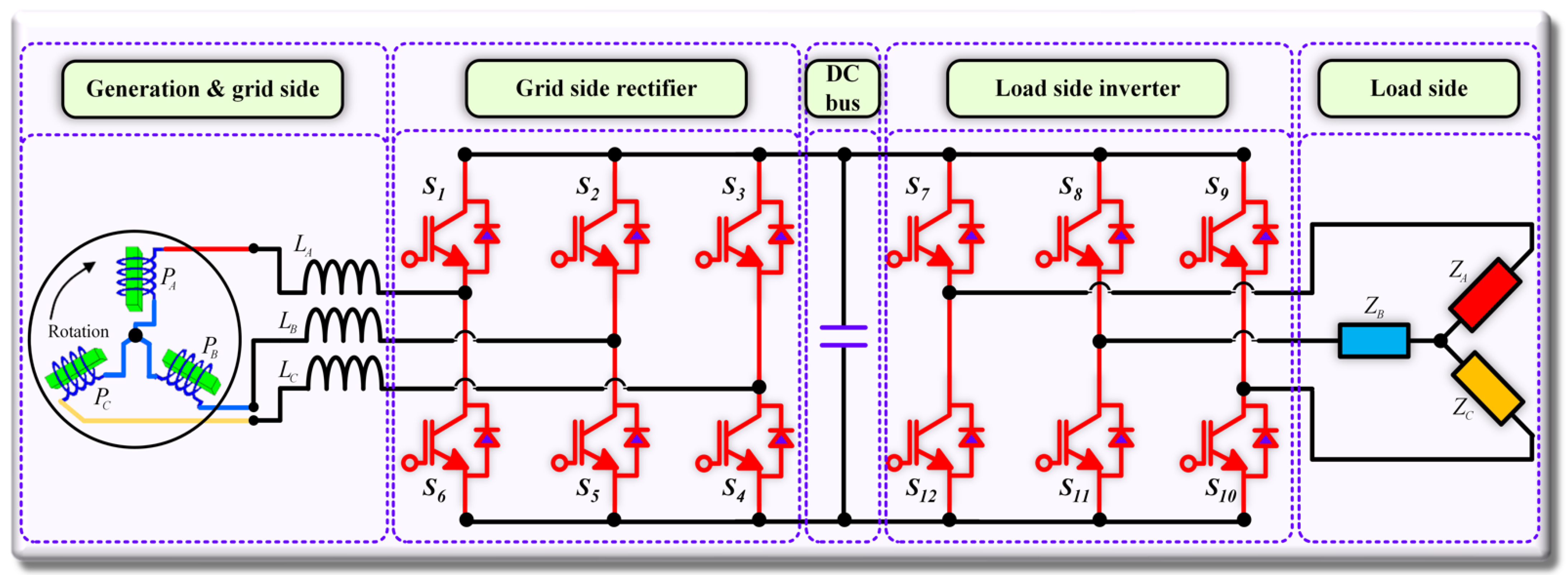
The AC/AC power converter is the commonly used topology that is most frequently employed in low-voltage and medium-voltage industrial systems [8]. Power converters employed in AC/AC power conversion can be classified into direct and indirect converter topologies. The indirect AC/AC power converter is termed a DC-link converter or AC/DC/AC converter. A back-to-back converter, or B2B, is an indirect AC/AC converter with a bidirectional structure that employs two stages of power conversion, as shown in Figure 1 [9].
A diode bridge rectifier and six active switches inverters make up the traditional AC/DC/AC converter for various industrial applications such as induction motor drives and grid integrations. This topology’s drawback is that the input grid current is non-sinusoidal and operates with a low power factor [10]. The diode bridge rectifier is further replaced by an active six-switch converter known as a back-to-back converter to increase the quality of input current [11]. For AC/DC/AC conversion, twelve active switches are needed. This solution makes the system complex and bulky because of the use of a higher number of controlled power switches and a complicated grid-size transformer for suppressing input current total harmonic distortion (THD) [12]. Apart from these, the two stages AC/DC/AC converter requires bulky filters at the inverter end for reducing THD from the inverter output voltage. The excessive use of magnetic core material like inductor filters raises some severe problems in the system [13,14,15]. Another important concern of a two-stage AC/AC converter is the DC-link capacitor [16]. In the DC-link circuits of contemporary power electronic converters, aluminum electrolytic capacitors are arguably the most frequently utilized capacitors. Additionally, multi-layer ceramic structures and metalized polypropylene structures are other technologies used in the manufacture of these capacitors. Modern capacitors used in DC circuits have significantly shrunk in size, yet they still make up the majority of the components that increase the size, weight, and cost of power converters [17]. Additionally, the capacitor is the component that sustains damage the most frequently as a result of poor operation and power grid disruptions. Because of this, the lifespan of the DC-link AC/AC power converter device prematurely shortens due to the usage of the most prevalent electrolytic capacitors [18,19,20]. For the aforementioned reasons, environmental and operational factors impacting the longevity of power converters, particularly high-power ones, are given special consideration, with a focus on DC-link capacitors [21]. An intriguing way to lower the price and size of power converters is to produce them without huge capacitors in their design (DC-link) [22,23]. Another complexity of two-stage DC-link AC/AC converters is the use of complicated pulse width modulation (PWM) techniques. Complex high-frequency PWM techniques are used for controlling both the AC/DC converter and the DC/AC converter of the DC-link converter. Due to high-frequency switching, the overall switching and conduction power loss increases which reduces the efficiency of the DC-link AC/AC converter [24,25].
Due to the aforementioned shortcomings of existing two-stage DC-link AC/AC power converters (AC/DC/AC converters), the two-stage typical AC/DC/AC converters and thyristor choppers are rapidly being replaced by single-stage direct AC/AC converters without DC-link capacitors, such as frequency changers and matrix converters [26]. The most popular topology for direct converters in low and medium-power applications is the cycloconverter (CCV), which connects the power supply to the machine directly using a series of power semiconductor switches to transform a three-phase or single-phase AC voltage with fixed magnitude and frequency into a three-phase AC voltage with variable magnitude and variable frequency. It enables effective power flow in both directions. With technical advantages in low-speed range and high-torque applications, such as grinding mills, CCV drives are an established technology [27,28]. Different topologies with various functions are available for AC/AC converters without DC-link capacitors. In a matrix-type single-stage AC/AC converter, the common DC link is removed in exchange for an increase in the number of active switches in order to lengthen the converter lifespan. For AC/AC conversion, there must be 18 active switches. As a result, complexity, and losses related to switches rise [29]. The only drive manufacturer with commercially available products based on single-stage AC/AC converters is Yaskawa Electric. Thus, the stage AC/AC converter is one of the most investigated but less industrially-applied converter topologies [30]. The main drawbacks of traditional single-stage AC/AC converters are high THD of the output voltage, SCR commutation complexity, and high-stress voltage on semiconductor switches. [31]. Different solutions for reducing the THD from the output voltage of single-stage AC/AC converters are available. Most of the solutions are related to modulation techniques and filters. The standard filter scheme [32] and advanced modulation techniques [33,34] were taken into consideration for the minimization of harmonic distortion. In order to enhance the output power’s quality, various modulation techniques were applied, including pulse width modulation (PWM) [35], sinusoidal PWM [36], space vector modulation, delta modulation, discrete amplitude modulation, and pulse density modulation (PDM) [37]. Another method for removing harmonics from the output voltage of an AC/AC power converter is delta modulation. However, the output voltage is controlled by an additional controller circuit, which adds expense and bulk to the architecture. For discrete amplitude modulation to produce a carrier wave for amplitude modulation (AM), an additional circuit topology is required, and for pulse density modulation (PDM), an additional delta-sigma analog to digital converter is required. As a result, conventional approaches with sophisticated modulation are not very appealing because they raise circuit complexity and expense.
Despite the extensive research conducted over the past 40 years and all the significant advantages connected with single-stage AC/AC power converters, such topologies are still not extensively used in the industry because of their very serious harmonic distortion problems. That’s why the reduction of THD for single-stage AC/AC power converters is always an industrial concern.
Apart from these, from the viewpoint of industrial application areas, three-phase induction motors have some advantages in terms of machine efficiency, power factor, and torque ripples compared to their single-phase counterparts. Therefore, in some low-power industrial applications, it is preferable to switch from single-phase to three-phase induction motor drives. We should change a single-phase supply to a three-phase supply, though, in some remote locations where there is only a single-phase utility available. The conventional method for changing a single-phase voltage to a three-phase voltage uses rotary, capacitor, or autotransformer converters. Most of these converters remain balanced only at one specified load. On the contrary, for low-power induction motor-driven traction applications, a three-phase induction motor drive from a single-phase utility supply is also considered a critical concern. So, it is highly desirable to develop a modular single-phase to three-phase AC/AC power converter to meet the industrial demand for drive applications.
In order to mitigate the problems associated with two-stage DC-link AC/AC converters and conventional single-stage AC/AC converters, a new single-stage AC/AC power converter is proposed in this paper. The proposed topology conducts single-phase to three-phase AC/AC power conversion. A multi-winding transformer has been utilized at the input side, and TRAIC switches are used to construct the proposed power converter. The specialty of the multi-winding transformer is to provide variable amplitude AC voltages as the inputs of the proposed power converter, which aids in producing a low harmonic distorted output voltage. The proposed AC/AC power converter:
- Employs single-stage power conversion;
- Can perform multiple order frequency conversion by changing the gate signals only;
- Mitigates the output voltage THD;
- Utilizes line frequency switching instead of high-frequency switching, which aids to reduces the power loss of the converter;
- Reduces the magnitude of detrimental lower-order harmonics;
- Can be used to drive low-cost three-phase induction motors in the industry from single-phase supply;
- Reduces the overall cost and circuit complexity due to the use of TRIAC instead of SCR;
- Can be used to drive a low-power three-phase traction motor from a single-phase supply;
- Can be considered the best candidate for the farmers to run their three-phase induction motor-driven water pump where only single-phase utility is available.
Instead of having the abovementioned promising merits of the proposed direct AC/AC power converter, the proposed AC/AC power converter has some drawbacks and challenges, which are the requirements of a complex structure multi-winding transformer and the requirement of a higher number of TRIACs with an increase of frequency conversion order. These shortcomings might be considered further research challenges.
The rest of the paper is organized as follows: the proposed AC/AC power converter topology, its operating principles, and simulated performance analysis are described in Section 2. Section 3 represents the experimental validation of the proposed AC/AC power converter. Analytical harmonics analysis for the proposed AC/AC power converter is described in Section 4. Result analysis and comparative analysis of the proposed AC/AC power converter with some existing topologies are depicted in Section 5. Finally, the paper is concluded in Section 6.
2. Proposed AC/AC Power Converter
This section describes the topology and operating principle of the proposed direct single-phase to three-phase step-down AC/AC power converter.
2.1. Topology of the Proposed AC/AC Power Converter
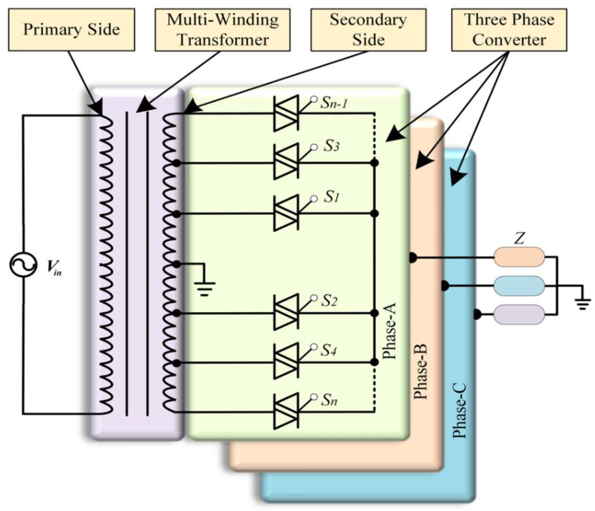
Figure 2 shows the generalized topology of the proposed single-phase to three-phase step-down AC/AC power converter. The proposed converter uses a 1:3 multi-winding center tapped transformer and bidirectional triode thyristor or bilateral triode thyristor (TRIAC) as a power semiconductor switch. The secondary side of the multi-winding transformer has three separate windings for driving a three-phase load. Each winding is isolated from the others and divided by some small sub-windings to create different voltage levels. Here, different voltage levels are created in each winding for desired frequency conversion by doubling the peak magnitude of the transformer output voltage to gate close sinusoidal waveform at the converter output. The frequency conversion order, m, can be divided into odd frequency conversion, mo, and even frequency conversion, me. For AC/AC frequency conversion, the conversion order, m, can be written as,
where fi is the input frequency, and fo is the converted output frequency. In conversion order, m is a positive integer value, and m = 3, 4, 5, …
Hence, the required number of windings for mo can be calculated as,
For me, the required number of windings is equal to the number of me, i.e.,
The required number of switches, Nso for mo can be calculated as,
For me, the required number of switches is equal to the number of me, i.e.,
2.2. Operating Principle of the Proposed AC/AC Converter
With the help of 3:1 (m = 3) and 4:1 (m = 4) frequency conversions, the operating principle of the proposed AC/AC power converter is described here. The single-phase AC voltage source is connected to the primary side of the multi-winding transformer in Figure 2. Now, the input AC voltage is divided into small AC voltage levels in the different segments of the transformer’s secondary winding. TRIAC switches are connected to each winding of the transformer secondary side to pass the corresponding winding voltage. Because of their high current flow capacity, TRIACs are used in this case. There is a total of nine operating modes required for the proposed single-phase to three-phase step-down AC/AC power converter to get 16.67 Hz (m = 3) and 12.5 Hz (m = 4) output frequency from 50 Hz supply. The nine operating modes are described in this section to understand the 16.67 Hz (m = 3) and 12.5 Hz (m = 4) frequency conversion, followed by the proposed AC/AC power converter. These operating modes are explained in detail, which may aid in the understanding of other frequency conversions also. The operating modes of the proposed AC/AC power converter are shown in Figure 3. m = 3 and m = 4 are taken into consideration for demonstrating the operating modes of the proposed AC/AC power converter. The operating modes are named as mode-1, mode-2, mode-3, mode-4, mode-5, mode-6, mode-7, mode-8, and mode-9, respectively. A detailed description of each of the modes is provided below.
Mode-1: In this mode, switch S1 for phase-A as well as phase-C and S4 for phase-B, creating a conduction path through the three-phase load, as shown in mode-1 of Figure 3. Phase-A and phase-C pass the positive half cycle, and phase-B passes the negative half cycle. The output voltage polarity of phase-A and phase-C remains the same with the input, but the output voltage polarity of phase-B is changed by 180°. Again, the amplitude of the half-cycle output voltage of phase-B is twice as compared to that of phase-A and phase-C. Thus, the converted output voltage expression for individual three phases can be written as,
Mode-2: In this mode, switch S4 for phase-A, S1 for phase-B, and phase-C create a conduction path through the three-phase load, as shown in mode-2 of Figure 3. Phase-A passes the positive half cycle, and phase-B and phase-C pass the negative half cycle of the input. The output voltage polarity of phase-B and phase-C remain the same width, followed by the input, but the output voltage polarity of phase-A is changed by 180°. Again, the amplitude of the half-cycle output voltage of phase-A is twice compared to phase-B and phase-C, respectively. Thus, the converted output voltage expression for individual three phases can be written as,
Mode-3: Switch S1 for phase-A as well as phase-B and S4 for phase-C take part in flowing the load current, as shown in mode-3 of Figure 3. On the contrary, phase-A and phase-B pass the positive half cycle followed by the input voltage, but phase-C passes the negative half cycle by 180° polarity reversal compared to the input voltage with twice amplitude. The output voltage expressions can be written as,
Mode-4: Here, switch S3 for phase-A, S1 for phase-B, and S4 for phase-C flow the load current as shown in mode-4 of Figure 3. Phase-A and phase-B pass the positive half cycle with the same polarity of the input voltage, but phase-C passes the negative half cycle by 180° polarity reversal of the input voltage. The half-cycle amplitude of phase-B is half compared to phase-A and phase-C, respectively. The output voltage expressions can be written as,
Mode-5: Switch S2 for phase-A, S4 for phase-B and S3 for phase-C flow the load current shown in the mode-5 of Figure 3. On the contrary, phase-A and phase-B pass the positive half cycle but phase-C passes the negative half cycle. The polarity of the phase phase-B is altered by 180° where phase-C remains same polarity of the input voltage. Therefore, the amplitude of the phase-A is half compared to the phase-B and phase-C, respectively. The output voltage expressions can be written as,
Mode-6: In this mode, switch S2 for phase-A as well as phase-C and S3 for phase-B, creating a current-carrying conduction path as shown in mode-6 of Figure 3. On the contrary, phase-A and phase-B pass the positive half cycle, and phase-C passes the negative half cycle. The output voltage polarity of phase-A and phase-C is altered by 180°, but phase-B remains the same, followed by the input voltage. The amplitude of the half-cycle output voltage of phase B is twice as compared to phase-A and phase-C, respectively. Thus, the converted output voltage expressions can be written as,
Mode-7: Here, switch S3 for phase-A, S2 for phase-B and phase-C flow the load current as shown in mode-7 of Figure 3. Phase-B and phase-C pass the positive half cycle with 180° polarity of the input voltage, but phase-A passes the negative half cycle with the same polarity of the input voltage. The half-cycle amplitude of phase-A is twice as compared to that of phase-B and phase-C. The output voltage expression can be written as,
Mode-8: Switch S4 for phase-A, S2 for phase-B and S3 for phase-C flow; the load current is shown in mode-8 of Figure 3. On the contrary, phase-A and phase-B pass the negative half cycle, but phase-C passes the positive half cycle. The polarity of phase-A and phase-B is altered by 180°, where phase-C remains the same polarity followed by the input voltage, and the amplitude of phase-B is half compared to phase-A and phase-C, respectively. The output voltage expressions can be written as,
Mode-9: In this mode, switch S1 for phase-A, S3 for phase-B and S4 for phase-C create a current-carrying conduction path as shown in mode-9 of Figure 3. On the contrary, phase-A and phase-B pass the negative half cycle, and phase-C passes the positive half cycle. The output voltage polarity of phase-A and phase-B remains the same, but phase-C is altered by 180° followed by the input voltage. The amplitude of the half-cycle output voltage of phase-A is half compared to phase-B and phase-C, respectively. Thus, the converted output voltage expressions can be written as,
Table 1 summarizes the corresponding switching state of the proposed single-phase to three-phase AC/AC power converter for frequency transformation of m = 3 (16.67 Hz) and m = 4 (12.5 Hz).
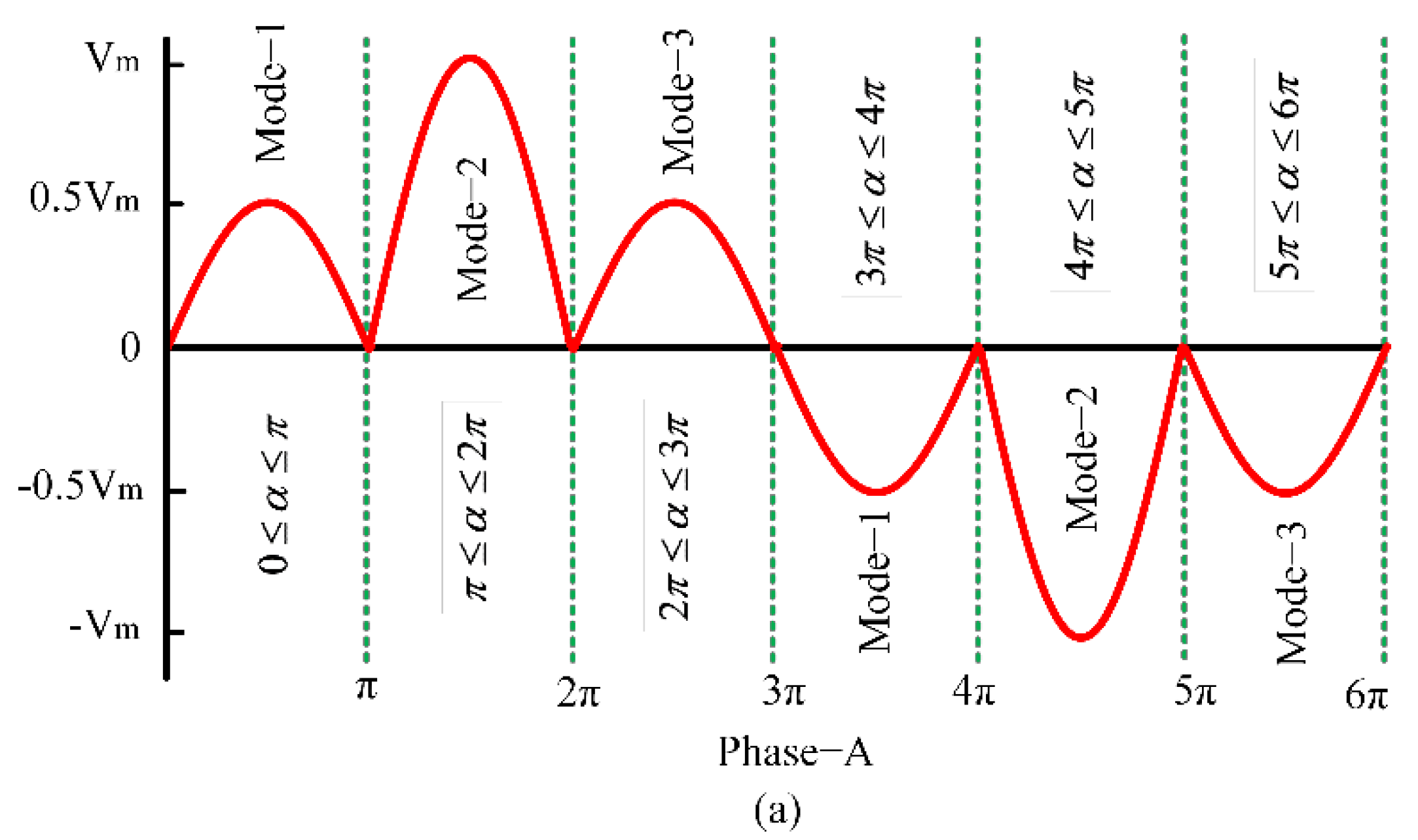
Here, mode-1, mode-2, and mode-3, as shown in Figure 3 are used for frequency conversion at m = 3 (16.67 Hz). In order to perform m = 3 frequency conversion (16.67 Hz output from 50 Hz input), the output side needs a total of six half-cycle portions where three of the half cycles occur during the positive side and another three half-cycles occur during the negative side. Whereas operating mode-1, mode-2, and mode-3 repeat twice as shown in Figure 4a–c, respectively. Hence, the six-state output voltage expression of the corresponding separated three phases is shown as follows:
On the contrary, a total of eight operating modes are required for frequency conversion at m = 4 (12.5 Hz) except mode-3. In order to perform m = 4 frequency conversion (12.5 Hz output from 50 Hz input), the output side needs a total of eight half-cycle portions where the four half-cycles occur during the positive side, and another four half-cycles occur during the negative side. In contrast, every operating mode except mode-3 is active, as shown in Figure 5a–c. Hence, the eight-state output voltage expression of the corresponding separated three phases is shown as follows:
2.3. Performance Analysis of the Proposed AC/AC Power Converter
Two distinct frequency conversions, named m = 3 (16.67 Hz output from 50 Hz input) and m = 4 (12.5 Hz output from 50 Hz input), were simulated in the MATLAB/Simulink software environment to analyze the performance and reliability of the proposed single- phase to three-phase step-down AC/AC power converter. The simulation parameters of the proposed AC/AC power converter are depicted in Table 2. The nominal power rating of the power converter is 1.8 kVA. Two thyristors equivalent TRIAC switches are used during the simulation. The on-state resistance (Ron), forward voltage drops (Vf), snubber resistance (Rs), and snubber capacitance (Cs) of the TRIAC are provided in Table 2. A three-phase, 1.5 hp induction motor is used as a load during the simulation.
A 1:3 multi-winding center-tapped transformer is used to convert the single-phase supply to a three-phase supply. Three separated converters are connected to the separated three winding of the transformer’s secondary side. Each winding of the transformer is divided into different sub-windings to create different voltage levels, and a TRAIC switch is connected to the sub-winding to pass the positive as well as the negative half cycle, respectively. Figure 6 illustrates the half-cycle phase conversion and inversion technique for converting a single-phase 50 Hz power source to a three-phase 16.67 Hz power source. The half-cycle phase conversion is done by the separated three converters connecting with the transformer’s three windings. Similarly, Figure 7 illustrates the half-cycle phase conversion and inversion technique for converting a single-phase 50 Hz power source to a three-phase 12.5 Hz power source. From Figure 6 and Figure 7, it is evident that the converted output voltage of each phase follows the sinusoidal pattern as closely as possible. The output waveforms of Figure 6 and Figure 7 are investigated for resistive load.
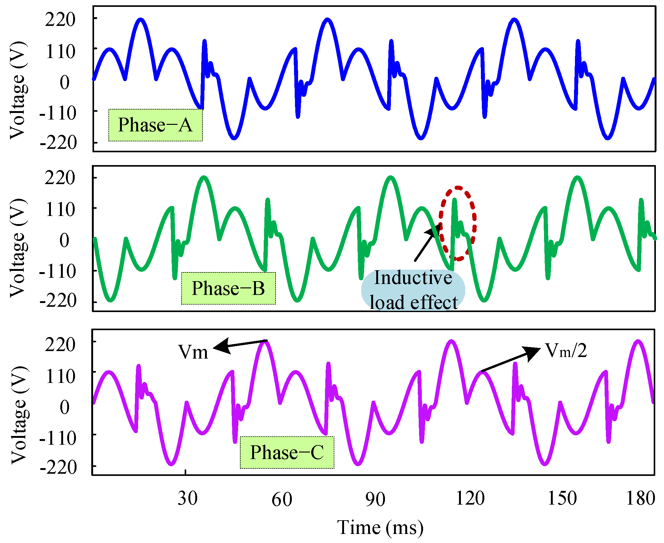
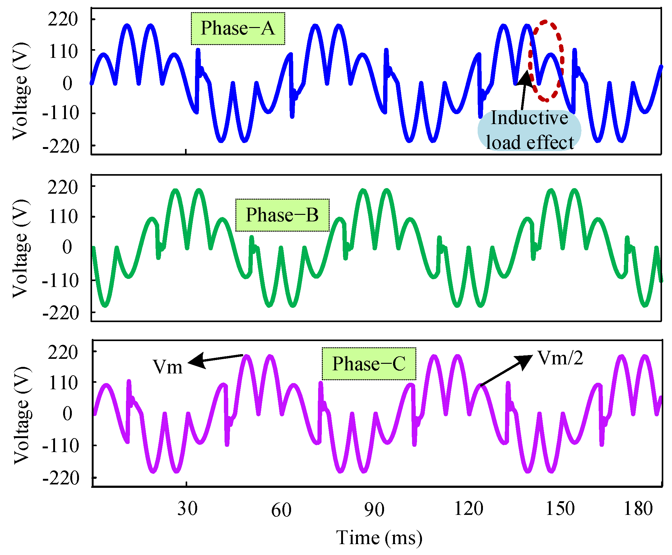
The performance of the proposed single-phase to three-phase AC/AC power converter is assessed here with RL load and double squirrel cage induction motor load also. Figure 8 and Figure 9 illustrate the single-phase to three-phase output voltage waveforms of 16.67 Hz (m = 3) and 12.5 Hz (m = 4) frequency conversion, respectively, for RL load.
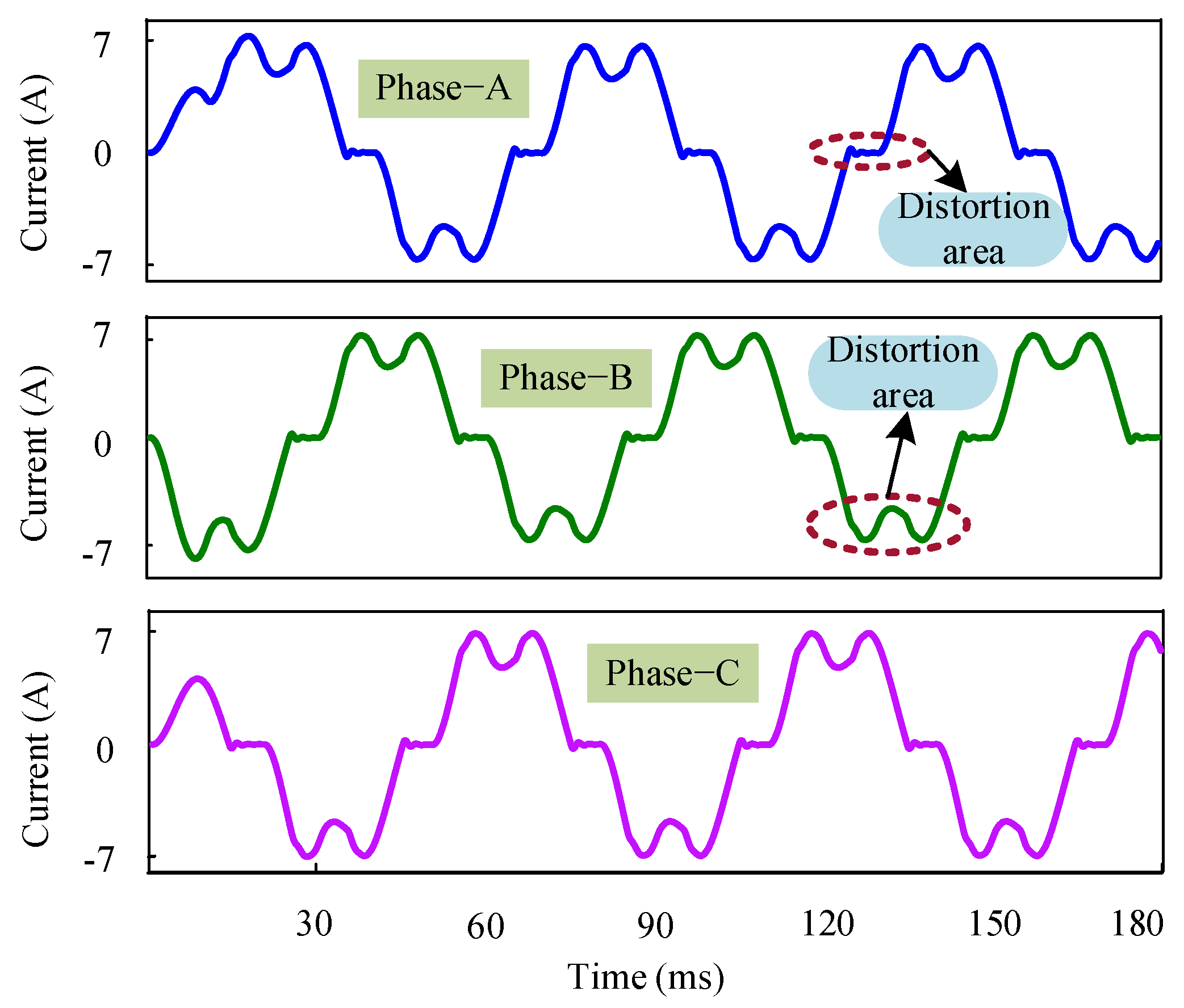
It is seen that the output voltage waveforms have little distortion because of the nature of inductive load. Figure 10 shows the output current waveforms of individual three-phases for m = 3 (16.67 Hz output from 50 Hz input). The output current of each phase has inductive load effect and the distortion area indicates that some harmonic components are present there due to inductive spike.
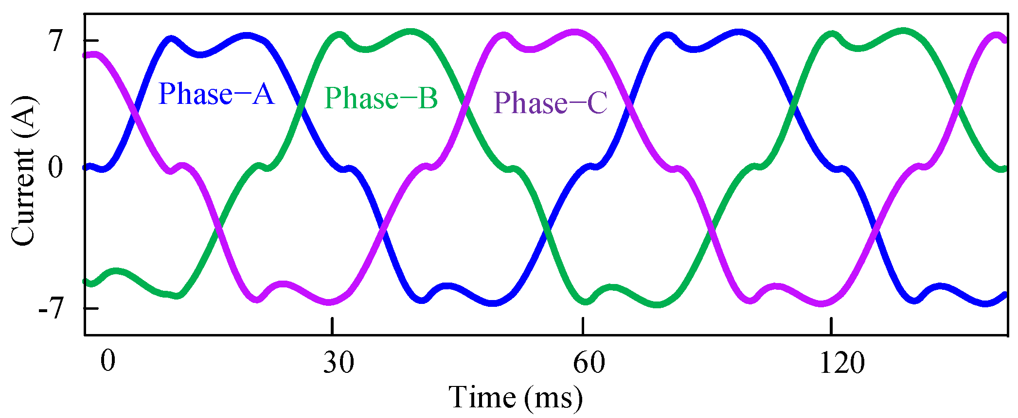
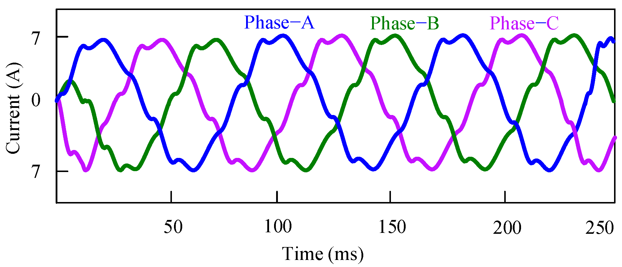
Figure 11 and Figure 12 show the combined three-phase load current waveforms for m = 3 (16.67 Hz output from 50 Hz input) and m = 4 (12.5 Hz output from 50 Hz input) frequency conversion order, respectively. It is noticeable that the distortion area of the three-phase load current is reduced for 12.5 Hz (m = 4) frequency conversion. So, it is clear that the power quality is improved when the frequency conversion order, m, is increased.
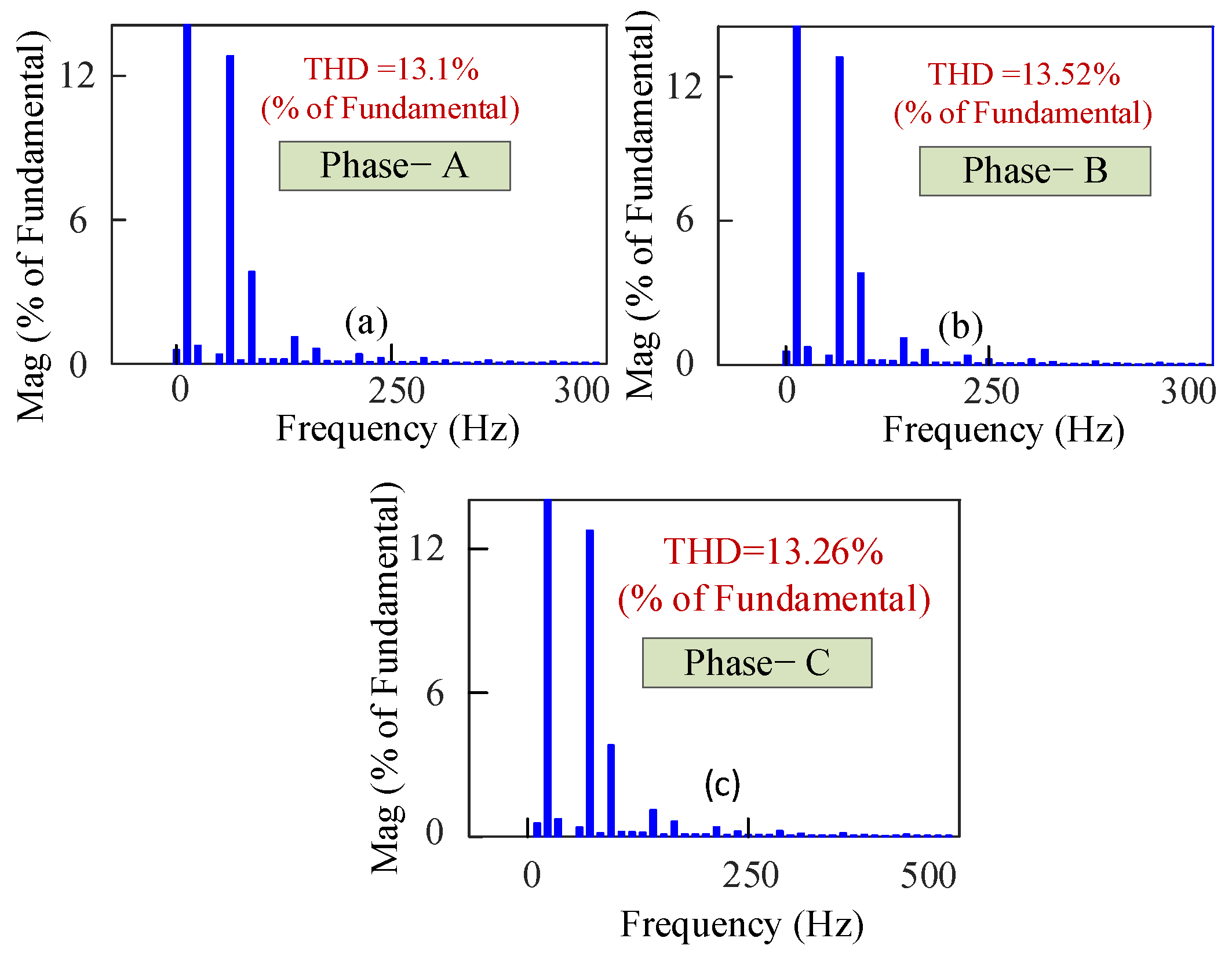
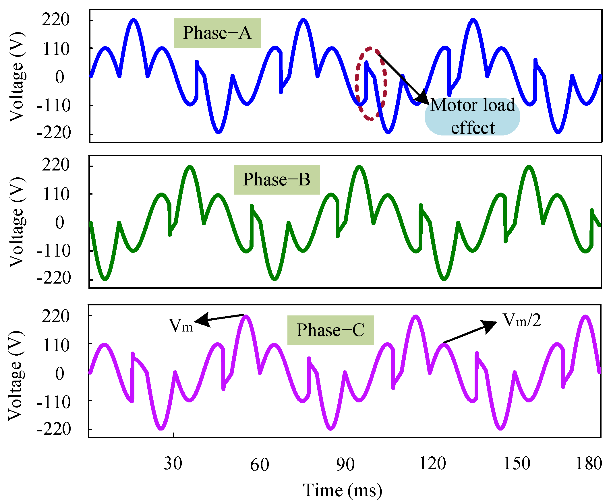
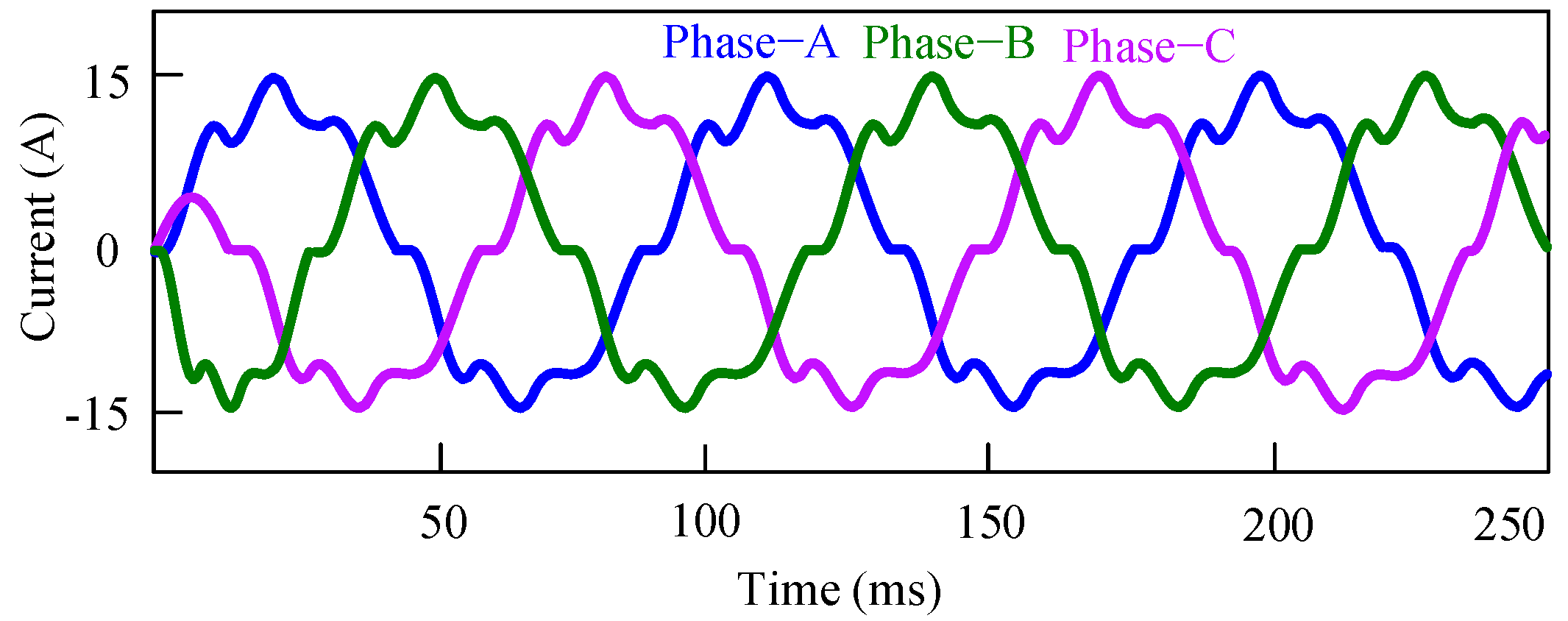
The harmonic spectrums of the three-phase load current of 16.67 Hz (m = 3) and 12.5 Hz (m = 4) frequency conversion are shown in Figure 13 and Figure 14, respectively, for RL load. The THDs for phase-A, phase-B, and phase-C are found 13.1%, 13.52%, and 13.26%, respectively as depicted in Figure 13a–c for m = 3 frequency conversion. Similarly, the THDs for phase-A, phase-B, and phase-C are recorded 10.14%, 10.37%, and 10.21%, respectively as depicted in Figure 14a–c for m = 4 frequency conversion. The THDs of the three-phase load current of 16.67 Hz (m = 3) and 12.5 Hz (m = 4) frequency are found to be 13% and 10% (average), respectively, for RL load. The power quality parameter, which is expressed in terms of THD, is improved by 3% by increasing the frequency conversion order, m because the output current follows a more sinusoidal wave shape. Figure 15 and Figure 16 illustrate the three-phase output voltage waveforms of 16.67 Hz (m = 3) and 12.5 Hz (m = 4) frequency conversion, respectively, for induction motor load. Because of the motor load, the output voltage waveforms show little distortion. Figure 17 and Figure 18 show the load current of 16.67 Hz (m = 3) and 12.5 Hz (m = 4) frequency conversion for the motor load.
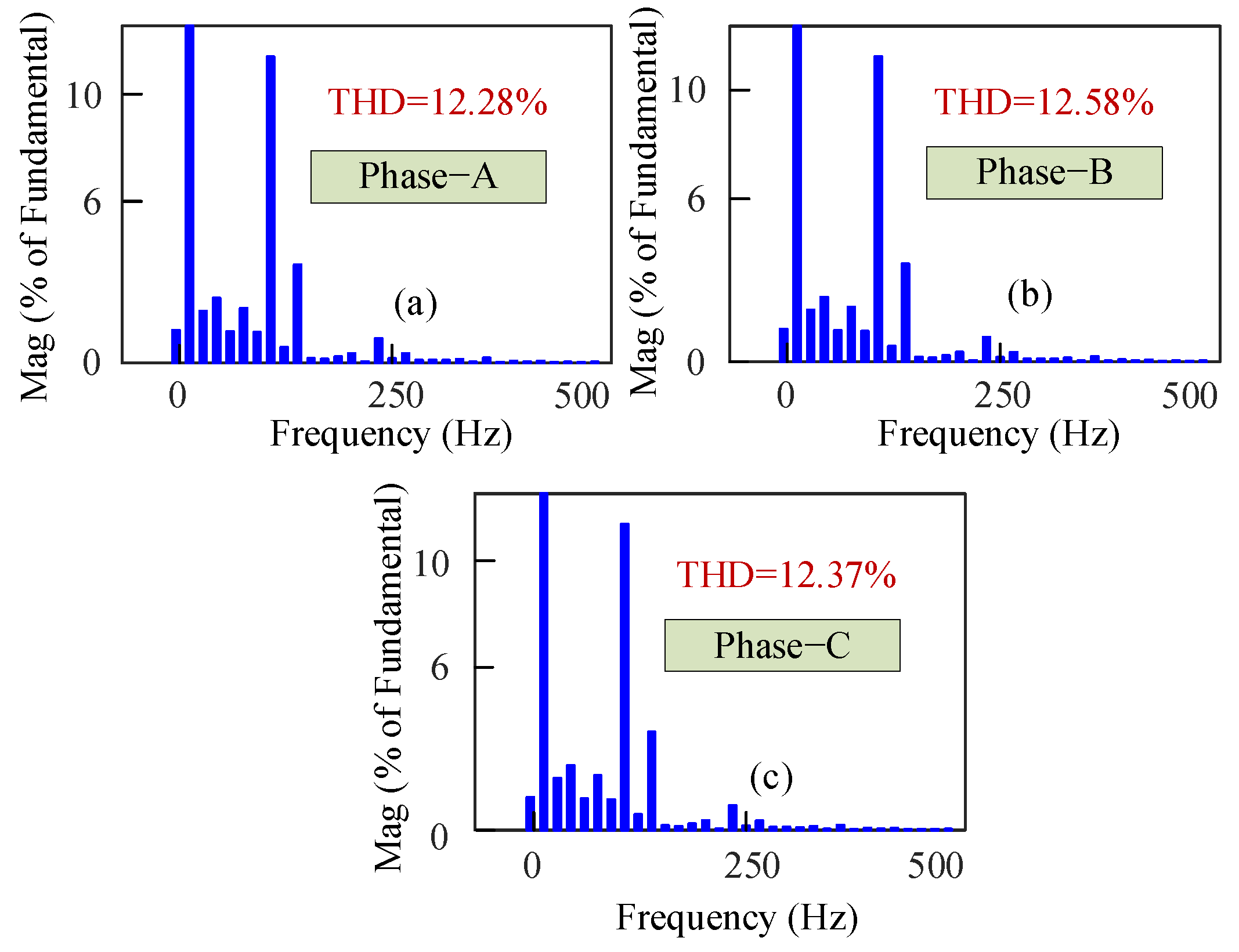
It is seen that the current wave-shape distortion of 12.5 Hz (m = 4) frequency conversion is less than that of 16.67 Hz (m = 3) frequency conversion. The THDs for phase-A, phase-B, and phase-C are found 17.31%, 17.67%, and 17.21%, respectively as depicted in Figure 19a–c for m=3 frequency conversion. Similarly, the THDs for phase-A, phase-B, and phase-C are recorded 12.28%, 12.58%, and 12.37%, respectively as depicted in Figure 20a–c for m=4 frequency conversion. The average THDs of the three-phase load currents of 16.67 Hz (m = 3) and 12.5 Hz (m = 4) frequency are found to be 17% and 12% (average), respectively, for the motor load as depicted in Figure 19 and Figure 20, respectively. Thus, the THD is improved by 5% by increasing the frequency conversion order, m. So, it can be claimed that by increasing the frequency conversion order (m = 5, 6, 7…), the THD of motor load current can be minimized to less than 5% as per the requirement of IEEE-519 standard.
3. Experimental Validation
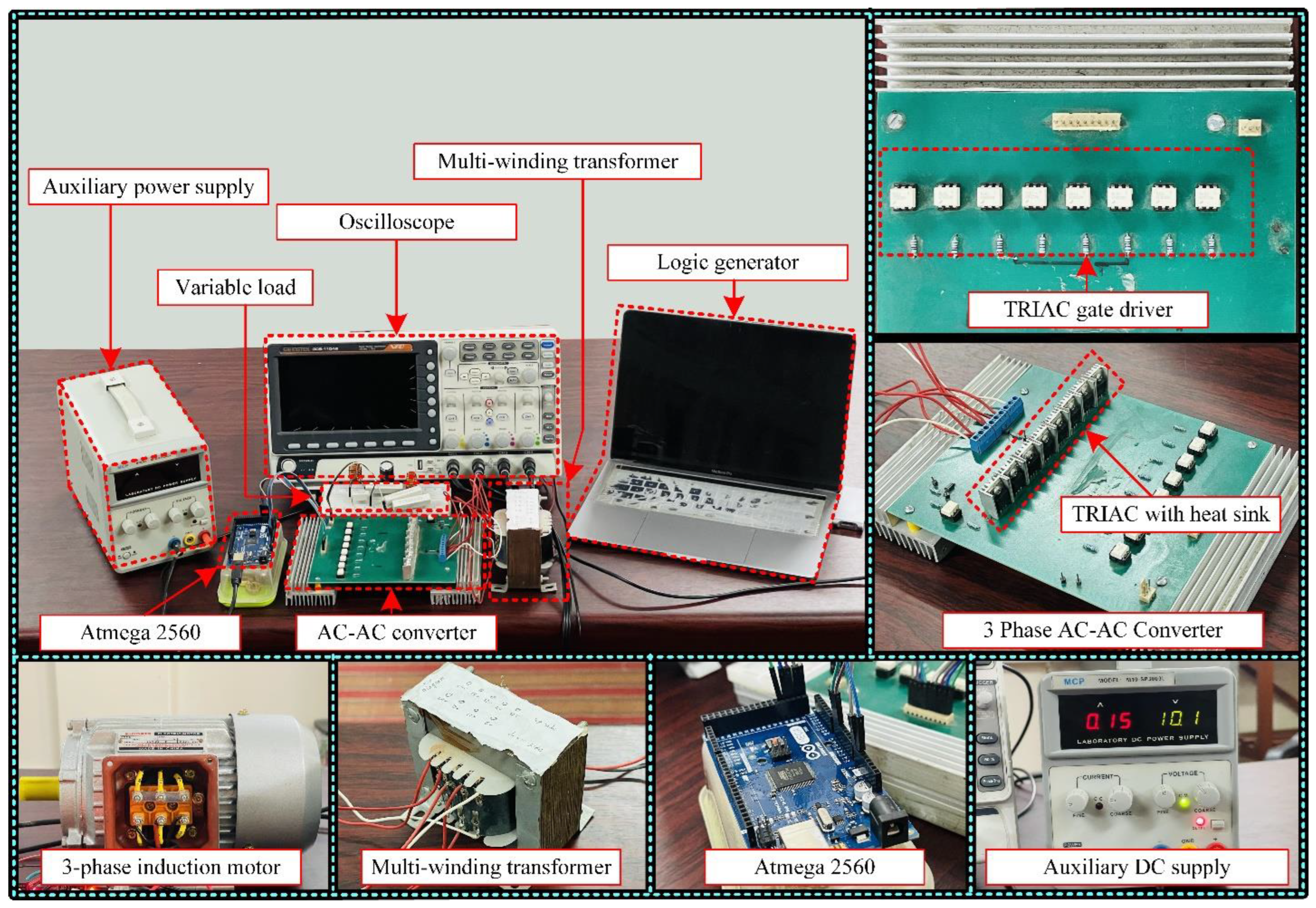
In order to verify the analysis and simulation results, a reduced scale prototype was built and tested in the laboratory. This condensed version emphasizes verifying the conceptual idea of the proposed converter topology. The photograph of the experimental setup is shown in Figure 21. The experimental parameters are provided in Table 3. BT 135 TRAIC switches are used to construct the proposed converter. For producing gate pulses for the TRIACs, zero-crossing detection (ZCD) circuit has been designed using a 4 N35 optocoupler. The zero-crossing control signal is feedback to the processor board. The Arduino ATmega2560 processor board is used here to control the overall circuit. The gate pulses are produced from the processor board based on zero-crossing information. After that, the gate pulses are passed through a gate driver circuit consisting of MOC3021 optocouplers. The MOC3021 ensures the isolation between the low-voltage processor board and high-voltage power switches of the proposed AC/AC power converter. This scaled-down converter is tested for an RL load to observe filtered current waveforms for both m = 3 (16.67 Hz output from 50 Hz input) and m = 4 (12.5 Hz output from 50 Hz input) frequency conversion, respectively.
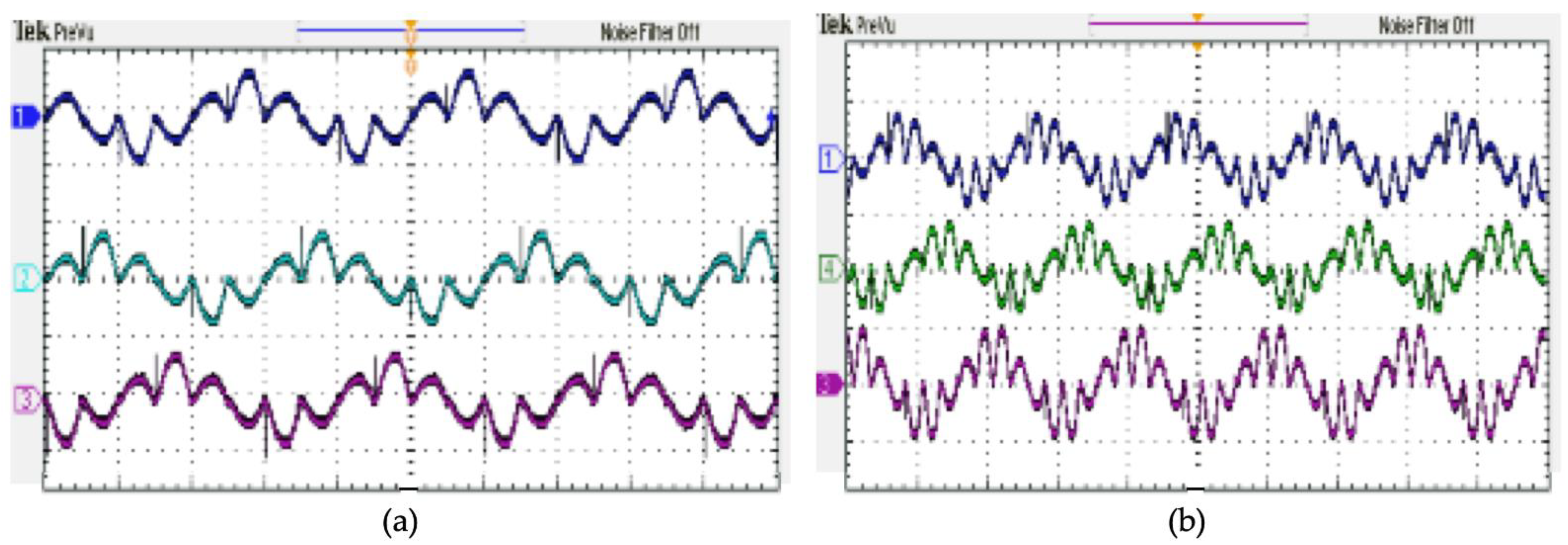
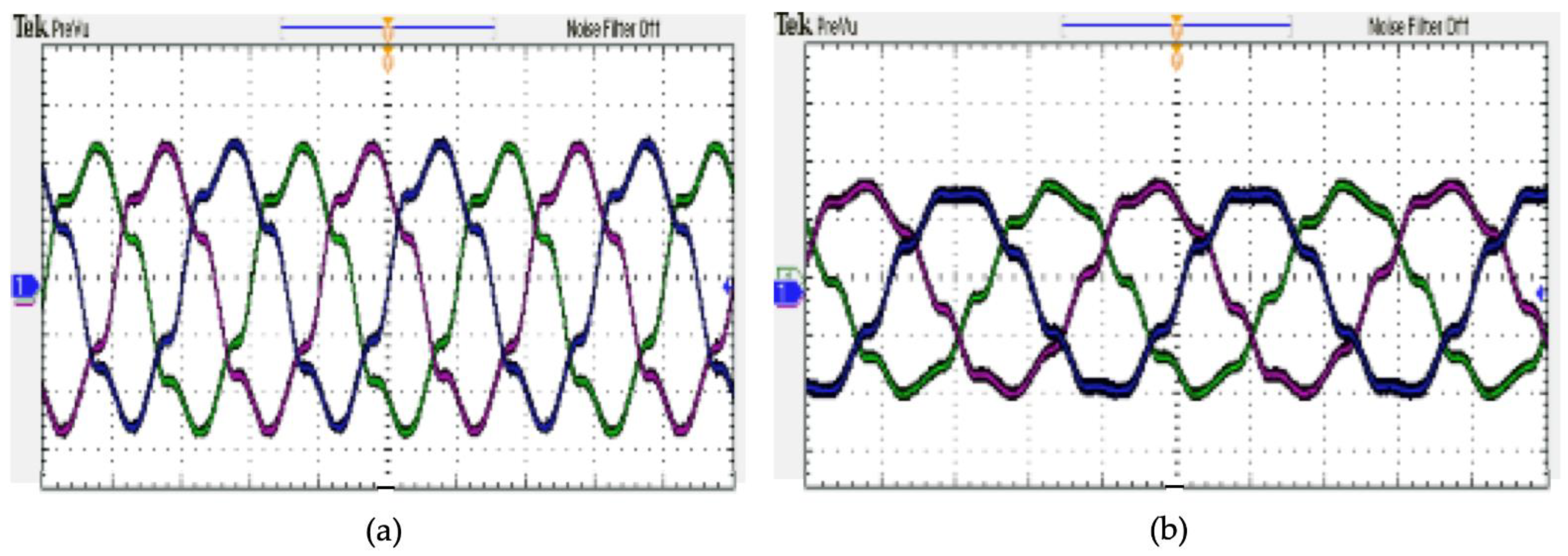
The gate drive signals are the main control pulses for the TRIACs to conduct certain frequency conversion operations. The experimental gate drive signals generated from the ArduinoMega2560 processor board for m = 3 (16.67 Hz output from 50 Hz input) and m = 4 (12.5 Hz output from 50 Hz input) frequency conversions are depicted in Figure 22 and Figure 23, respectively. The converted output voltage waveforms of m = 3 (16.67 Hz output from 50 Hz input) and m = 4 (12.5 Hz output from 50 Hz input) frequency conversions are shown in Figure 24a,b, respectively, against an RL load. Some spikes are notable in the voltage waveforms of Figure 24a,b, respectively, which are due to the impact of reactive load. From Figure 24a,b, it is evident that the experimental result agrees well with the simulation results of Figure 8 and Figure 9, respectively. Figure 25a depicts the experimental output current waveforms for m = 3 (16.67 Hz output from 50Hz input) frequency conversion order. The current waveforms look more sinusoidal than voltage waveforms that are because the currents are filtered by the load inductance. Similarly, the output current waveform for m = 4 (12.5 Hz output from 50 Hz input) frequency conversion order is shown in Figure 25b. The current of the waveform of m = 4 frequency conversion is more sinusoidal than that of the current waveform of m = 3 frequency conversion. Thus, it is clear that with the increase of frequency conversion order, both the voltage and current waveforms will follow a more sinusoidal pattern, and overall harmonic distortion will be decreased consequently.
4. Analytical Harmonics Analysis for the Proposed AC/AC Power Converter
The THD of the proposed single-phase to three-phase step-down AC/AC power converter is evaluated in this section for 16.67 Hz (m = 3) frequency conversion only. The THD of the output waveform of the AC/AC power converter can be determined by the Fourier series expression, as shown below.
where, m is the frequency conversion ratio. To analyze the harmonic distortion of the output voltage by using Equation (47), all ao and an Fourier coefficients are zero, except the bn coefficient. All even harmonic components are zero for the bn coefficient, leaving only odd harmonic components. As a result, the Fourier series expression of the traditional m = 3 frequency conversion output voltage can be written by Equation (48) using the half-cycle pairs method [38].
where the first term represents the 3rd harmonic component and the second term represents any harmonic components other than the 3rd order harmonic. The frequency conversion ratio and harmonic order are denoted by ‘m’ and ‘n’, respectively, in Equation (48).
The half-cycle pair method can also be used to measure the harmonic distortion of the proposed AC/AC power converter output voltage, followed by Equation (48). Similar procedures can be followed for calculating the analytical harmonic components of the output voltage waveforms of the AC/AC power converter. Thus, any order (m = 3,4,5, 6,….) harmonic components and overall THD can be evaluated using Equation (47) and Equation (48).
5. Result Analysis and Comparisons
Table 4 summarizes a comparative analysis for m = 3 (16.67 Hz output from 50 Hz input) order frequency conversion in terms of load current THD for RL load and induction motor load, respectively. For motor load, the DC component is found 3.22% for the conventional 3:1 converter, whereas 1.10% DC component is found for the proposed 3:1 converter. The highly 3rd harmonic component is completely suppressed by the proposed 3:1 converter for RL load, whereas 30.89% 3rd harmonic component is found for the conventional 3:1 power converter for the same load. For motor load, the 3rd harmonic component is 0.07% for the proposed 3:1 power converter, whereas 37.68% 3rd harmonic component is found for the conventional 3:1 converter. The 5th harmonic component is found at 28.45% and 40.07% for the conventional 3:1 converter with RL load and motor load, respectively. On the contrary, 12.42% and 16.21% 5th harmonic components are found for the proposed 3:1 power converter with RL load and motor load, respectively. The 7th harmonic component is recorded at 8.73% and 12.46% for the conventional 3:1 converter with RL load and motor load, respectively. At the same time, 3.65% and 3.80% 7th harmonic components are found for the proposed 3:1 power converter with RL load and motor load, respectively. The 8th, 9th, 10th, 12th, 14th, and 15th harmonic components are completely nullified by the proposed 3:1 power converter. The overall current THDs of the conventional 3:1 converter are found to be 42.97% and 57.81% for RL load and motor load, respectively. On the contrary, 13.00% and 17.31% current THDs are recorded for the proposed 3:1 power converter with RL load and motor load, respectively. From Table 4, it is clearly observable that the proposed 3:1 power converter outperformed than conventional 3:1 converter in terms of all harmonic components and overall THD for both RL and motor load, respectively.
Table 5 summarizes the comparative analysis results for m = 4 (12.5Hz output from 50Hz input) order frequency conversion in terms of load current THD for RL load and induction motor load, respectively. The 3rd harmonic component for RL load and motor load is found at 32.49% and 44.73%, respectively, with the conventional 4:1 converter. On the contrary, 6.03% and 4.44% 3rd harmonic components are found for RL load and motor load, respectively, with the proposed 4:1 power converter. The 5th harmonic components are recorded 21.07% and 34.62% for the conventional 4:1 converter with RL load and motor load, respectively. On the contrary, 2.20% and 1.74% 5th harmonic components are found for the proposed 4:1 power converter with RL load and motor load, respectively. The overall current THDs of the conventional 4:1 converter are found to be 49.82% and 78.09% for RL load and motor load, respectively. On the contrary, 12.00% and 16.35% current THDs are recorded for the proposed 4:1 power converter with RL load and motor load, respectively. The proposed power converter also outperforms than conventional converter for 4:1 frequency conversion also, as cleared in Table 5.
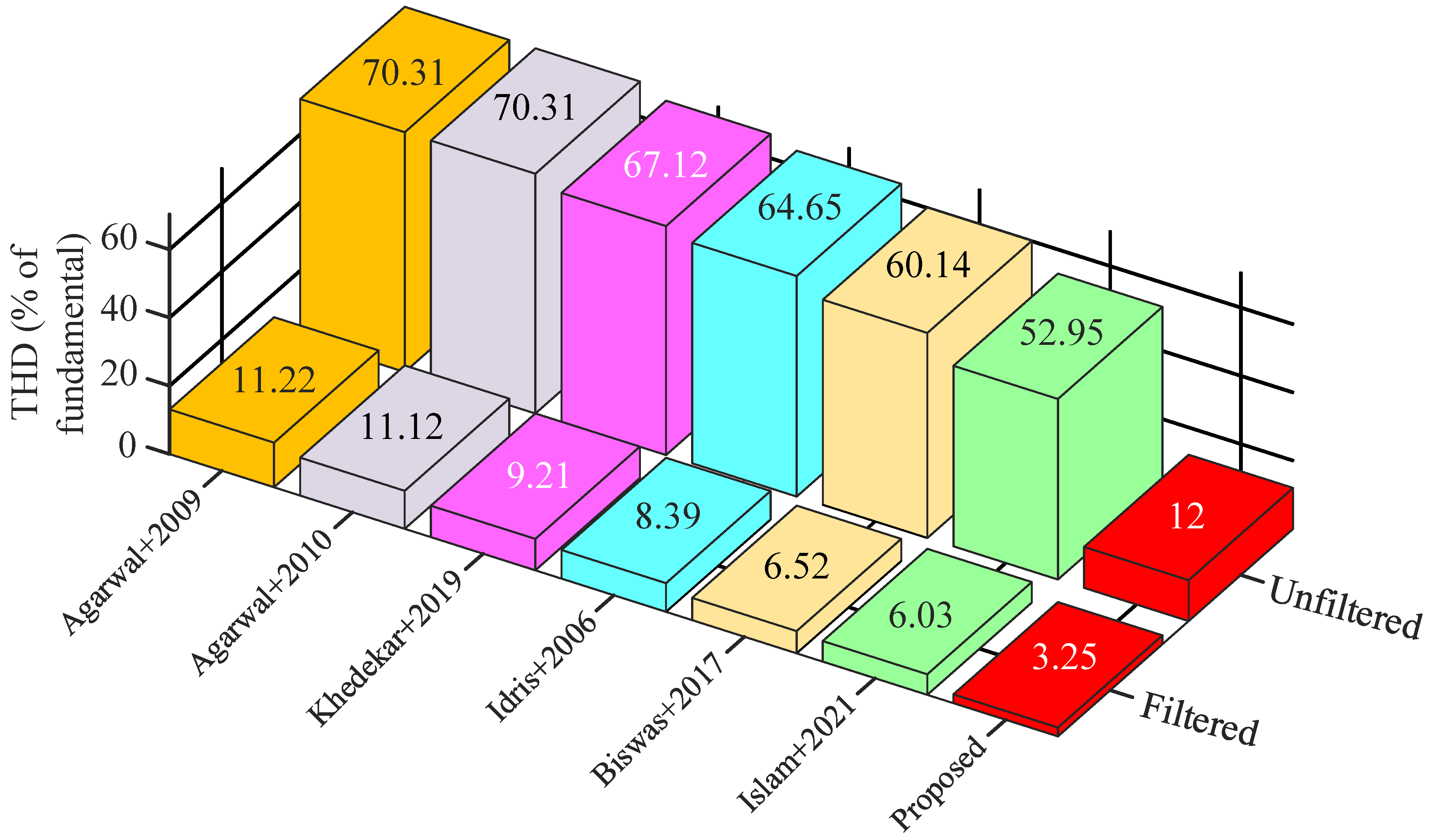
A comparative study has also been conducted in terms of current THD for both filtered and unfiltered conditions among various AC/AC power converter topologies, as depicted in Figure 26. This comparison is conducted against the RL condition for the m = 4 frequency conversion order. The unfiltered THDs for AC/AC power converter of [39,40,41,42,43,44] are 70.31%, 70.31%, 67.12%, 64.65%, 60.14%, and 52.95%, respectively. In contrast, the filtered THDs for AC/AC power converter of [39,40,41,42,43,44] is 11.22%, 11.12%, 9.21%, 8.39%, 6.52%, and 6.03%, respectively. Among all filtered THDs, none of them follow the IEEE-519 power quality standard. On the contrary, the filtered and unfiltered THDs are found to be 3.25% and 12.00%, respectively, for the proposed AC/AC power converter. The filtered THD of the proposed AC/AC power converter follows the IEEE-519 power quality standard. Thus, the proposed AC/AC power converter outperforms those of existing counterparts in terms of current THD, which ensures the better power density of the proposed AC/AC power converter.
6. Conclusions
In this paper, a new topology of direct single-phase to three-phase AC/AC power converter is introduced. The proposed converter is designed with a multi-winding transformer and TRIAC switches. The performance of the proposed AC/AC converter is analyzed and tested through computer simulation and experimental evaluation against different load type. The proposed converter outperforms than conventional counterpart in terms of individual harmonic components mitigation and overall THD reduction of the output voltage/current. For m = 3 (16.67Hz output from 50 Hz input) frequency conversion order, the overall current THD gets reduced by approximately 30% (Table 3) for RL load and 40% for motor load with the proposed AC/AC power converter. For m = 4 (12.5 Hz output from 50 Hz input) frequency conversion order, the overall current THD gets reduced by approximately 38% (Table 4) for RL load and 60% for motor load by utilizing the proposed topology. The switch count is reduced by 50% as compared to conventional SCR based single-phase to three-phase AC/AC power converter. Due to the use of TRIAC switches, the overall gate driving complexity also gets reduced for the proposed AC/AC power converter. The proposed AC/AC power converter can perform any order frequency conversion without changing the circuit topology by modifying only the line frequency switching pulses. Due to the use of line frequency switching pulses instead of high-frequency modulated gate pulses, the proposed AC/AC power converter can be considered the best candidate for reduced power loss and highly efficient power conversion applications. Although it is notable that direct AC/AC converters without DC-link have not been implemented on an industrial scale, this type of advanced direct AC/AC power converter without DC-link may reopen the door of further research interest to the industrial community.
Author Contributions
Conceptualization, S.P.B. and M.S.U.; methodology, S.P.B. and M.R.I.; software, M.S.U. and S.M.; validation, S.P.B., S.M. and J.N.; formal analysis, M.R.I.; investigation, S.P.B. and J.N.; resources, M.R.I. and J.N.; data curation, S.M., writing—original draft preparation, S.P.B.; writing—review and editing, M.R.I.; visualization, M.S.U.; supervision, M.R.I.; project administration, S.P.B. and M.R.I.; funding acquisition, M.R.I. All authors have read and agreed to the published version of the manuscript.
Funding
This research received no external funding.
Data Availability Statement
Not applicable.
Conflicts of Interest
The authors declare no conflict of interest.
References
- Jibhakate, C.; Chaudhari, M.; Renge, M. A Reduced Switch AC-AC Converter with the Application of D-STATCOM and Induction Motor Drive. Electronics 2018, 7, 110. [Google Scholar] [CrossRef] [Green Version]
- Barrios, M.A.; Cárdenas, V.; Sandoval, J.M.; Guerrero, J.M.; Vasquez, J.C. A Cascaded DC-AC-AC Grid-Tied Converter for PV Plants with AC-Link. Electronics 2021, 10, 409. [Google Scholar] [CrossRef]
- Varajão, D.; Araújo, R.E. Modulation Methods for Direct and Indirect Matrix Converters: A Review. Electronics 2021, 10, 812. [Google Scholar] [CrossRef]
- Szczesniak, P. Challenges and Design Requirements for Industrial Applications of AC/AC Power Converters without DC-Link. Energies 2019, 12, 1581. [Google Scholar] [CrossRef] [Green Version]
- Vishnuram, P.; Dayalan, S.; Thanikanti, S.B.; Balasubramanian, K.; Nastasi, B. Single Source Multi-Frequency AC-AC Converter for Induction Cooking Applications. Energies 2021, 14, 4799. [Google Scholar] [CrossRef]
- Afshari, E.; Khodabandeh, M.; Amirabadi, M. A Single-Stage Capacitive AC-Link AC–AC Power Converter. IEEE Trans. Power Electron. 2019, 34, 2104–2118. [Google Scholar] [CrossRef]
- Liu, C.; Guo, D.; Shan, R.; Cai, G.; Ge, W.; Huang, Z.; Wang, Y.; Zhang, H.; Wang, P. Novel Bipolar-Type Direct AC–AC Converter Topology Based on Non-Differential AC Choppers. IEEE Trans. Power Electron. 2019, 34, 9585–9599. [Google Scholar] [CrossRef]
- Ma, D.; Chen, W.; Shu, L.; Qu, X.; Gao, S.; Hou, K. A Multiport AC–AC–DC Converter for Soft Normally Open Point. IEEE Trans. Circuits Syst. II Express Br. 2022, 69, 2146–2150. [Google Scholar] [CrossRef]
- Wang, H.; Blaabjerg, F. Reliability of capacitors for DC-Link applications in power electronic converters—An overview. IEEE Trans. Ind. Appl. 2014, 50, 3569–3578. [Google Scholar] [CrossRef] [Green Version]
- Diab, M.S.; Elserougi, A.A.; Abdel-Khalik, A.S.; Massoud, A.M.; Ahmed, S. A Nine-Switch-Converter-Based Integrated Motor Drive and Battery Charger System for EVs Using Symmetrical Six-Phase Machines. IEEE Trans. Ind. Electron. 2016, 63, 5326–5335. [Google Scholar] [CrossRef]
- Liu, C.; Wu, B.; Zargari, N.; Xu, D. A novel nine-switch PWM rectifier-inverter topology for three-phase UPS applications. In Proceedings of the 2007 European Conference on Power Electronics and Applications, Aalborg, Denmark, 2–5 September 2007; pp. 1–10. [Google Scholar]
- Alves, W.C.; Morais, L.M.F.; Cortizo, P.C. Design of an Highly Efficient AC-DC-AC Three-Phase Converter Using SiC for UPS Applications. Electronics 2018, 7, 425. [Google Scholar] [CrossRef] [Green Version]
- Komarzyniec, G.; Aftyka, M. Operating Problems of Arc Plasma Reactors Powered by AC/DC/AC Converters. Appl. Sci. 2020, 10, 3295. [Google Scholar] [CrossRef]
- Petrauskas, G.; Svinkunas, G. Application of Single-Phase Supply AC-DC-AC VFD for Power Factor Improvement in LED Lighting Devices Loaded Power Distribution Lines. Appl. Sci. 2022, 12, 5955. [Google Scholar] [CrossRef]
- Petrauskas, G.; Svinkunas, G.; Jonaitis, A.; Giannakis, A. Application of Novel AC–AC Matrix VFD for Power Factor Improvement in Conventional AC–DC–AC VFD-Loaded Power Distribution Lines. Electronics 2022, 11, 997. [Google Scholar] [CrossRef]
- Kolar, J.W.; Friedli, T.; Rodriguez, J.; Wheeler, P.W. Review of three-phase PWM AC–AC converter topologies. IEEE Trans. Ind. Electron. 2011, 58, 4988–5006. [Google Scholar] [CrossRef]
- Szcze’sniak, P.; Kaniewski, J.; Jarnut, M. AC/AC power electronic converters without DC energy storage: A review. Energy Convers. Manag. 2015, 92, 483–497. [Google Scholar] [CrossRef]
- Empringham, L.; Kolar, J.W.; Rodriguez, J.; Wheeler, P.W.; Clare, J.C. Technological issues and industrial application of matrix converters: A review. IEEE Trans. Ind. Electron. 2013, 60, 4260–4271. [Google Scholar] [CrossRef]
- Abo-Khalil, A.G.; Alyami, S.; Alhejji, A.; Awan, A.B. Real-Time Reliability Monitoring of DC-Link Capacitors in Back-to-Back Converters. Energies 2019, 12, 2369. [Google Scholar] [CrossRef] [Green Version]
- Plazas-Rosas, R.A.; Orozco-Gutierrez, M.L.; Spagnuolo, G.; Franco-Mejía, É.; Petrone, G. DC-Link Capacitor Diagnosis in a Single-Phase Grid-Connected PV System. Energies 2021, 14, 6754. [Google Scholar] [CrossRef]
- Ashraf, N.; Abbas, G.; Ullah, N.; Alzaed, A.N.; Raza, A.; Raza, M.T.; Farooq, U. A New Dual Polarity Direct AC-AC Voltage Regulator Ensuring Voltage Step-Up and Step-Down Capabilities. Appl. Sci. 2021, 11, 11944. [Google Scholar] [CrossRef]
- Ashraf, N.; Abbas, G.; Ullah, N.; Alahmadi, A.A.; Awan, A.B.; Zubair, M.; Farooq, U. A Simple Two-Stage AC-AC Circuit Topology Employed as High-Frequency Controller for Domestic Induction Heating System. Appl. Sci. 2021, 11, 8325. [Google Scholar] [CrossRef]
- Wang, R.; Huang, M.; Lu, C.; Wang, W. A Direct Three-Phase AC–AC Matrix Converter-Based Wireless Power Transfer System for Electric Vehicles. Appl. Sci. 2020, 10, 2217. [Google Scholar] [CrossRef] [Green Version]
- Sadeghi, Z.; Shahparasti, M.; Rajaei, A.; Laaksonen, H. Three-Level Reduced Switch AC/DC/AC Power Conversion System for High Voltage Electric Vehicles. Sustainability 2022, 14, 1620. [Google Scholar] [CrossRef]
- Mahanta, A.; Biswas, S.P. THD Reduction of Single-Phase to Single-Phase Step-Down Cycloconverter Using Multiwinding Transformer. In Proceedings of the 2019 5th International Conference on Advances in Electrical Engineering (ICAEE), Dhaka, Bangladesh, 26–28 September 2019; pp. 108–112. [Google Scholar] [CrossRef]
- Ashraf, N.; Abbas, G.; Ullah, N.; Al-Ahmadi, A.A.; Raza, A.; Farooq, U.; Jamil, M. Investigation of the Power Quality Concerns of Input Current in Single-Phase Frequency Step-Down Converter. Appl. Sci. 2022, 12, 3663. [Google Scholar] [CrossRef]
- Abu-Siada, A.; Budiri, J.; Abdou, A.F. Solid State Transformers Topologies, Controllers, and Applications: State-of-the-Art Literature Review. Electronics 2018, 7, 298. [Google Scholar] [CrossRef] [Green Version]
- Lumbreras, D.; Gálvez, E.; Collado, A.; Zaragoza, J. Trends in Power Quality, Harmonic Mitigation and Standards for Light and Heavy Industries: A Review. Energies 2020, 13, 5792. [Google Scholar] [CrossRef]
- Rahman, K.; Al-Emadi, N.; Iqbal, A.; Rahman, S. Common mode voltage reduction technique in a three-to-three phase indirect matrix converter. IET Electr. Power Appl. 2018, 12, 254–263. [Google Scholar] [CrossRef]
- Friedli, T.; Kolar, J.W. Milestones in Matrix Converter Research. IEEE J. Ind. Devices Appl. 2012, 1, 2–14. [Google Scholar] [CrossRef] [Green Version]
- Uddin, M.S.; Biswas, S.P.; Islam, M.R.; Anower, M.S.; Kouzani, A.Z.; Mahmud, M.A.P. A New Generalized Step-Down Single-Stage AC/AC Power Converter. Sustainability 2020, 12, 9181. [Google Scholar] [CrossRef]
- Basic, D.; Ramsden, V.S.; Muttik, P.K. Selective compensation of cycloconverter harmonics and inter harmonics by using a hybrid power filter system. In Proceedings of the 2000 IEEE 31st Annual Power Electronics Specialists Conference, Galway, Ireland, 23–23 June 2000; pp. 1137–1142. [Google Scholar]
- Taufik, T.; Adamson, J.; Prabuwono, A.S. Pulse density modulated soft-switching single-phase cycloconverter. In Proceedings of the 2011 IEEE Applied Power Electronics Colloquium (IAPEC), Johor Bahru, Malaysia, 18–19 April 2011; pp. 189–194. [Google Scholar]
- Mazumder, S.K.; Rathore, A.K. Primary-Side-Converter-Assisted Soft-Switching Scheme for an AC/AC Converter in a Cycloconverter-Type High-Frequency-Link Inverter. IEEE Trans. Ind. Electron. 2011, 58, 4161–4166. [Google Scholar] [CrossRef]
- Babaei, E.; Heris, A.A. PWM-based control strategy for forced commutated cycloconverters. In Proceedings of the 2009 IEEE Symposium on Industrial Electronics & Applications, Kuala Lumpur, Malaysia, 4–6 October 2009; pp. 669–674. [Google Scholar]
- Agarwal, V.; Agarwal, A. FPGA based delta modulated cyclo-converter. In Proceedings of the 2011 5th International Power Engineering and Optimization Conference, Shah Alam, Selangor, Malaysia, 6–7 June 2011; pp. 301–305. [Google Scholar]
- Yan, Z.; Xu, S.; Han, X.; Sun, X.; Li, J. A novel de-re-couple modulation strategy for full-wave mode single-phase high-frequency link inverter. In Proceedings of the 2014 IEEE Transportation Electrification Conference & Expo Asia-Pacific (ITEC Asia-Pacific), Beijing, China, 31 August–3 September 2014; pp. 1–4. [Google Scholar]
- Ashraf, N.; Hanif, A.; Farooq, U.; Asad, M.U.; Rafiq, F. Half cycle pairs method for harmonic analysis of cycloconverter voltage waveform. In Proceedings of the 2013 International Conference on Open Source Systems and Technologies, Lahore, Pakistan, 16–18 December 2013; pp. 97–102. [Google Scholar]
- Agarwal, A.; Agarwal, V. Harmonic reduction in AC to AC converter by trapezoidal modulation technique. In Proceedings of the 2009 International Conference on Power Systems, Kharagpur, India, 27–29 December 2009; pp. 1–6. [Google Scholar]
- Agarwal, A.; Agarwal, V. Design of delta-modulated generalized frequency converter. IEEE Trans. Ind. Electron. 2010, 57, 3724–3729. [Google Scholar] [CrossRef]
- Khedekar, A.; Badade, D.; Ugawekar, H.; Kale, S.; Kulkarni, R.D.; Kumari, M. Simulation of single phase to single phase step down cycloconverter for industrial application. In Proceedings of the 2019 International Conference on Nascent Technologies in Engineering (ICNTE), Navi Mumbai, India, 4–5 January 2019; pp. 1–6. [Google Scholar]
- Idris, Z.; Hamzah, M.K. Implementation of a new single-phase cycloconverter based on single-phase matrix converter topology using sinusoidal pulse width modulation with passive load condit. In Proceedings of the 2006 1ST IEEE Conference on Industrial Electronics and Applications, Singapore, 24–26 May 2006; pp. 1–6. [Google Scholar]
- Biswas, A.; Chaudhari, S. Harmonic reduction in single phase AC-AC converter. Indian J. Sci. Technol. 2017, 10, 1–7. [Google Scholar]
- Islam, T.; Fayek, H.H.; Rusu, E.; Rahman, F. Triac based novel single phase step-down cycloconverter with reduced THDs for variable speed applications. Applied Sciences 2021, 11, 8688. [Google Scholar] [CrossRef]
Figure 1.
Conventional DC-link two-stage AC/AC variable frequency power converter.

Figure 2.
A generalized circuit configuration of the proposed single-phase to three-phase AC/AC power converter.
Figure 2.
A generalized circuit configuration of the proposed single-phase to three-phase AC/AC power converter.

Figure 3.
Operating modes of the proposed AC/AC power converter for m = 3 (16.67 Hz) and m = 4 (12.5 Hz) order frequency conversion with 50 Hz supply frequency.
Figure 3.
Operating modes of the proposed AC/AC power converter for m = 3 (16.67 Hz) and m = 4 (12.5 Hz) order frequency conversion with 50 Hz supply frequency.
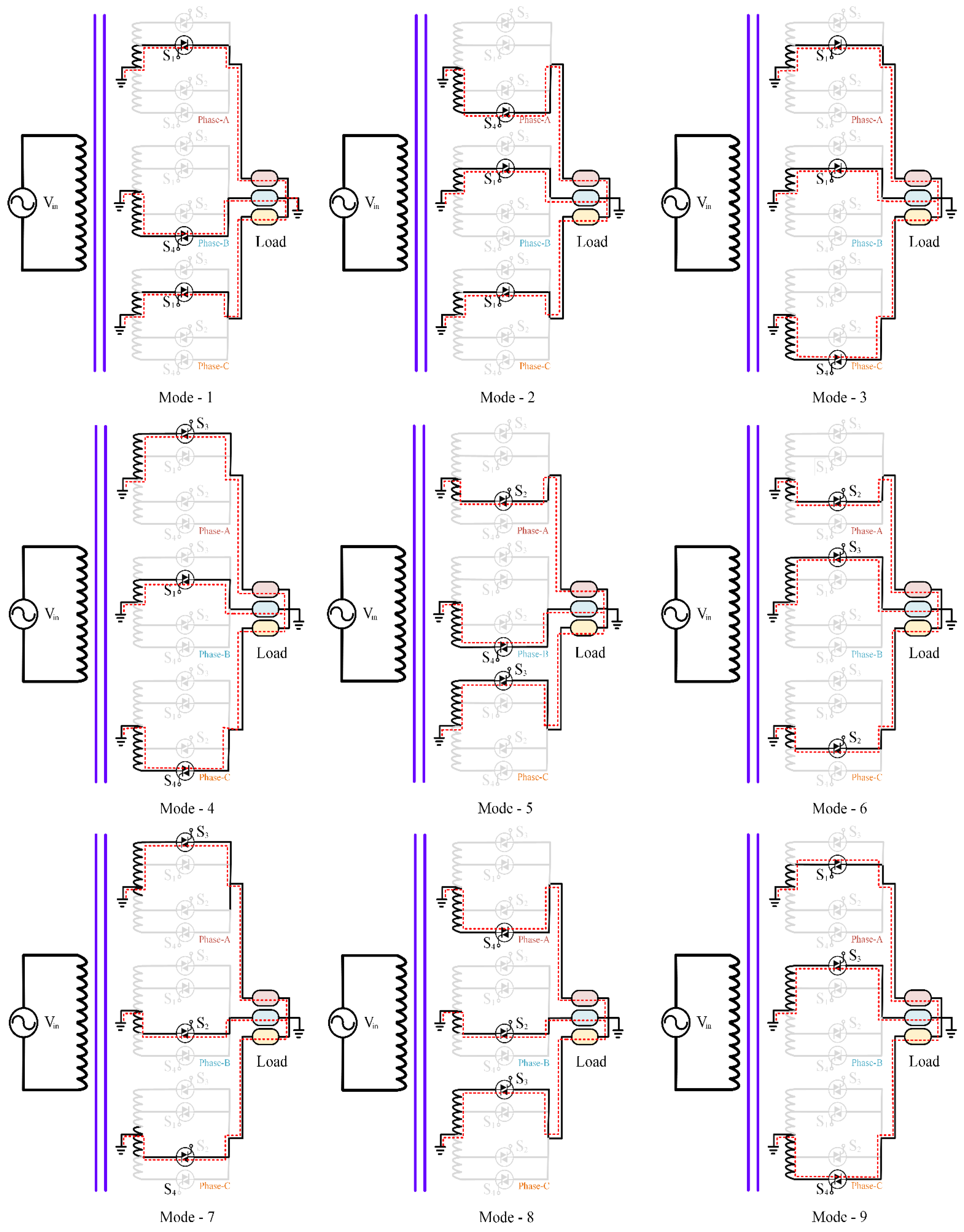
Figure 4.
Output voltage waveforms of (a) phase-A, (b) phase-B, and (c) phase-C for m = 3 order frequency conversion mode.
Figure 4.
Output voltage waveforms of (a) phase-A, (b) phase-B, and (c) phase-C for m = 3 order frequency conversion mode.

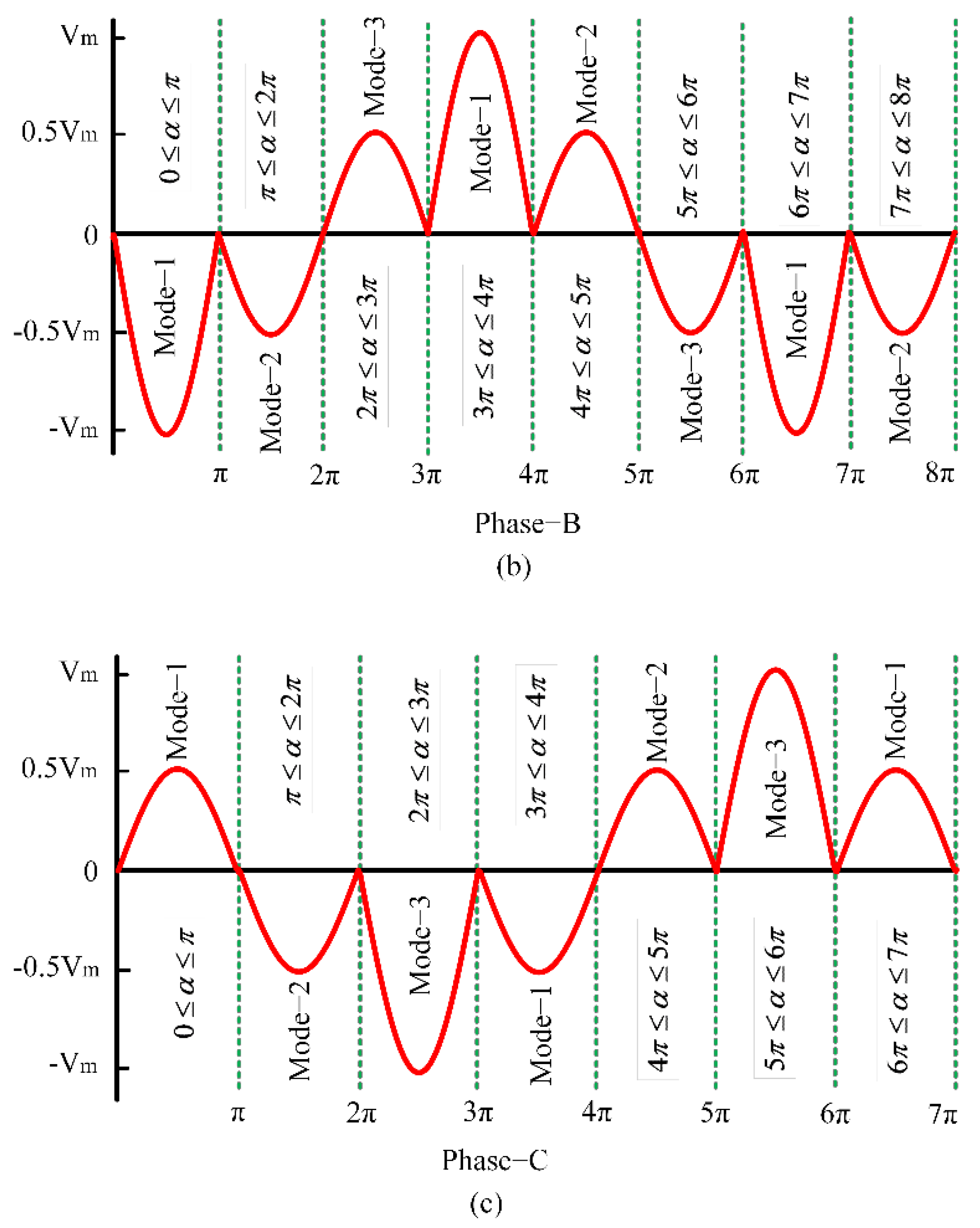
Figure 5.
Output voltage waveforms of (a) phase-A, (b) phase-B and (c) phase-C for m = 4 order frequency conversion mode.
Figure 5.
Output voltage waveforms of (a) phase-A, (b) phase-B and (c) phase-C for m = 4 order frequency conversion mode.
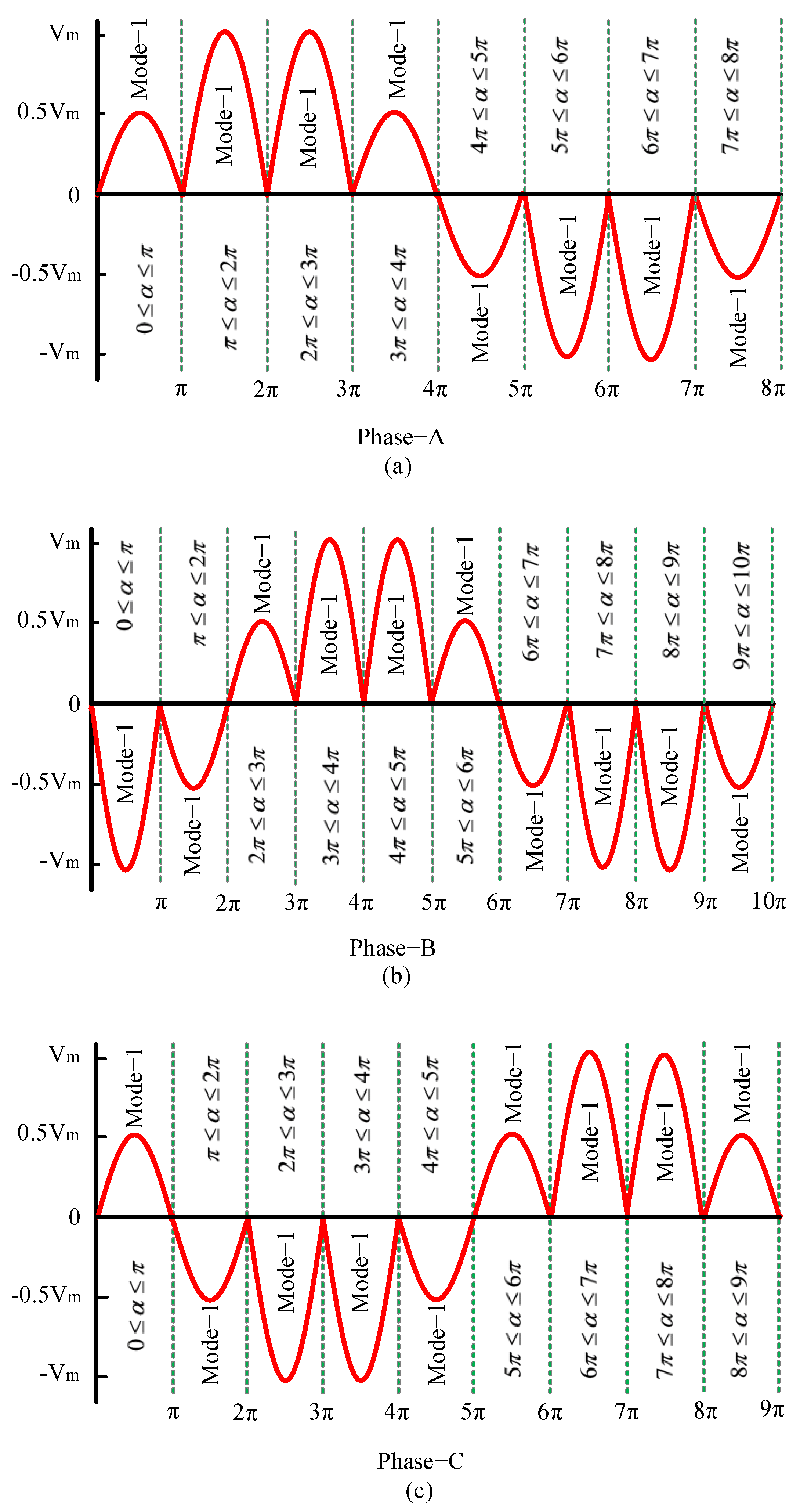
Figure 6.
Simulated input-output voltage waveforms of the proposed single-phase to three-phase AC/AC power converter for m = 3 (16.67 Hz output from 50 Hz input).
Figure 6.
Simulated input-output voltage waveforms of the proposed single-phase to three-phase AC/AC power converter for m = 3 (16.67 Hz output from 50 Hz input).
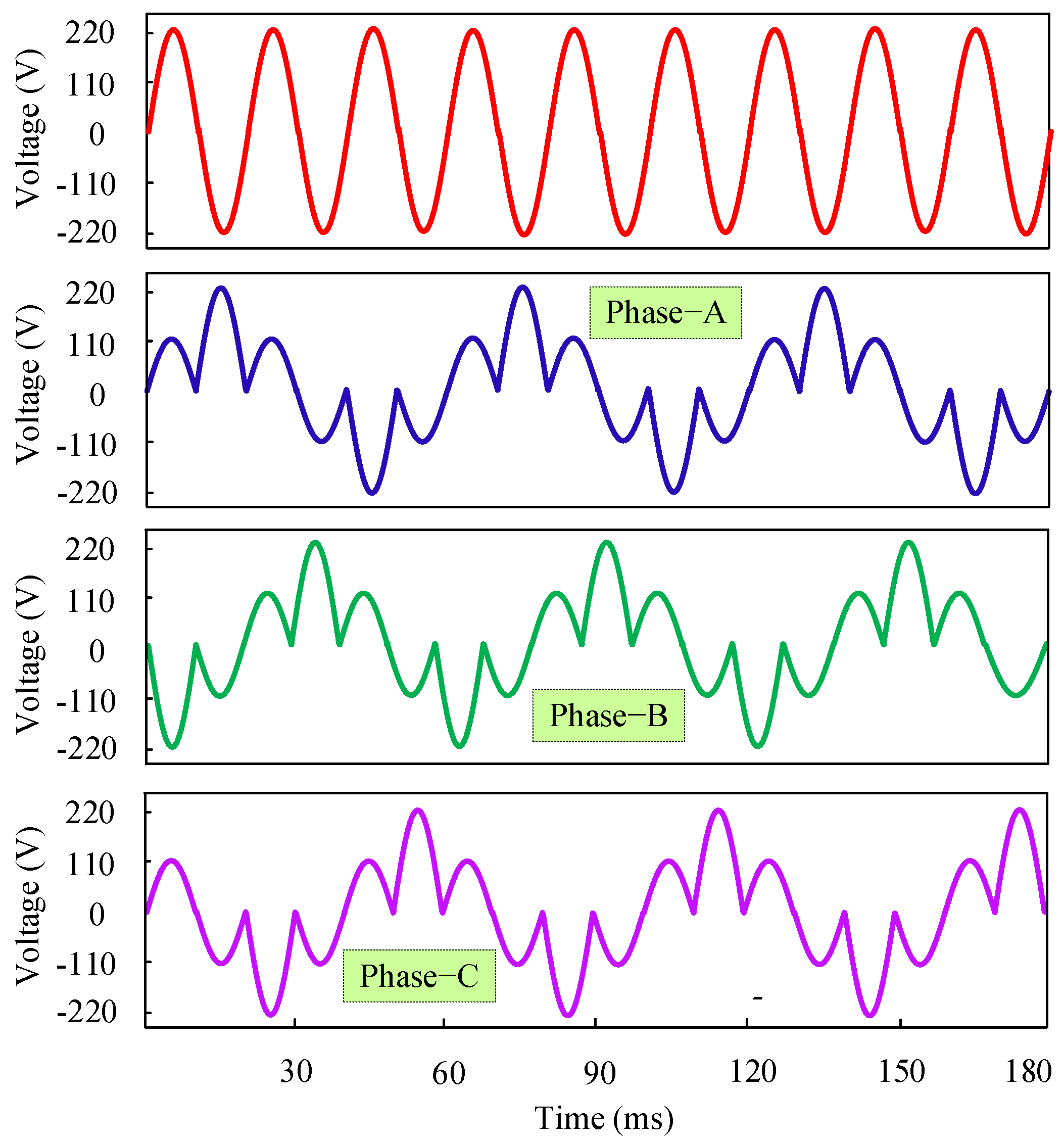
Figure 7.
Simulated input-output voltage waveforms of the proposed single-phase to three-phase AC/AC power converter for m = 4 (12.5 Hz output from 50 Hz input).
Figure 7.
Simulated input-output voltage waveforms of the proposed single-phase to three-phase AC/AC power converter for m = 4 (12.5 Hz output from 50 Hz input).
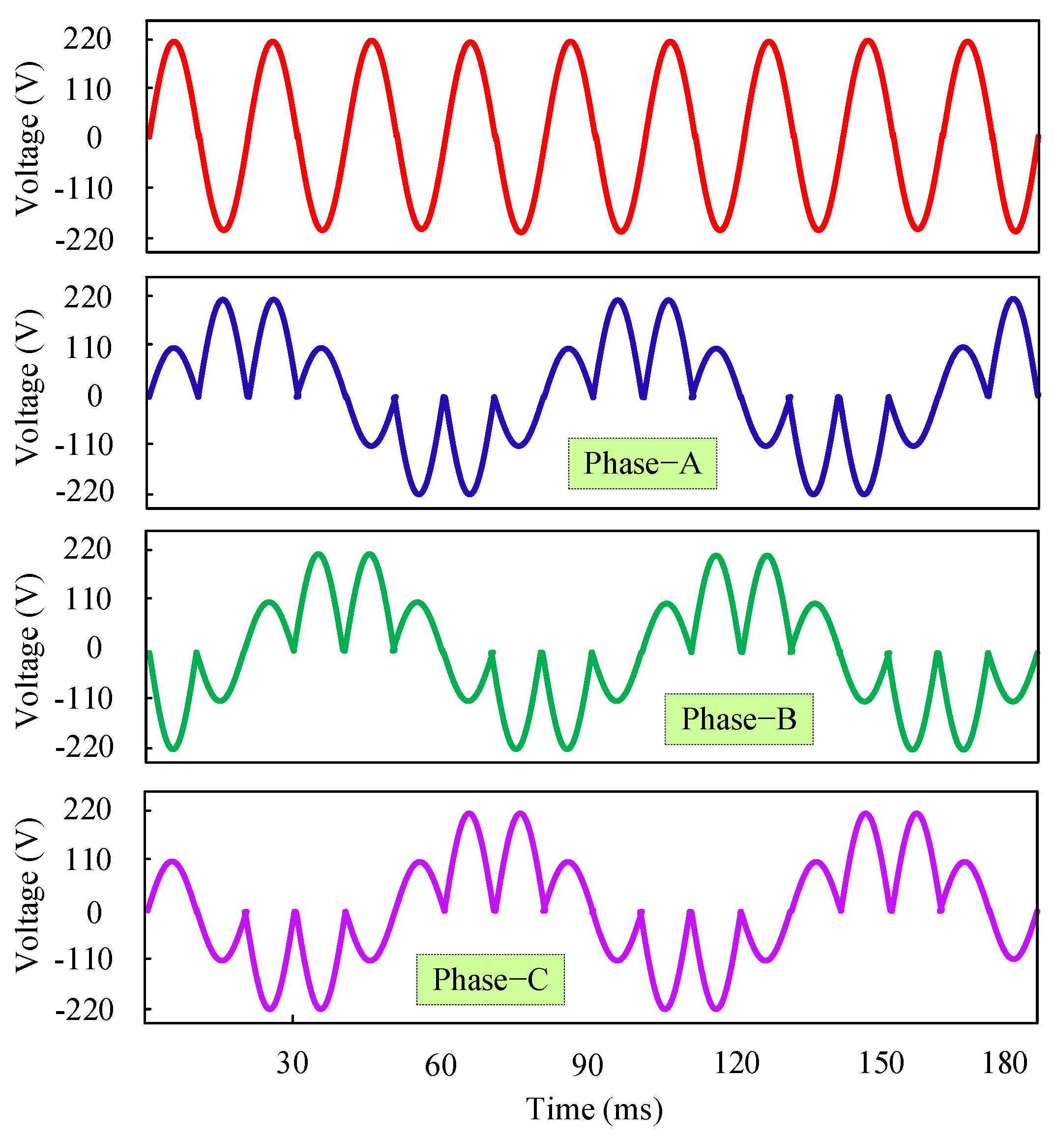
Figure 8.
Simulated input-output voltage waveforms of the proposed single-phase to three-phase AC/AC power converter for m = 3 (16.67 Hz output from 50 Hz input) for RL load.
Figure 8.
Simulated input-output voltage waveforms of the proposed single-phase to three-phase AC/AC power converter for m = 3 (16.67 Hz output from 50 Hz input) for RL load.

Figure 9.
Simulated input-output voltage waveforms of the proposed single-phase to three-phase AC/AC power converter for m = 4 (12.5 Hz output from 50 Hz input) for RL load.
Figure 9.
Simulated input-output voltage waveforms of the proposed single-phase to three-phase AC/AC power converter for m = 4 (12.5 Hz output from 50 Hz input) for RL load.

Figure 10.
Simulated separated three-phase output current waveforms of 16.67 Hz (m = 3) frequency conversion for RL load.
Figure 10.
Simulated separated three-phase output current waveforms of 16.67 Hz (m = 3) frequency conversion for RL load.

Figure 11.
Simulated combined three-phase output current waveforms of 16.67 Hz (m = 3) frequency conversion for RL load.
Figure 11.
Simulated combined three-phase output current waveforms of 16.67 Hz (m = 3) frequency conversion for RL load.

Figure 12.
Simulated combined three-phase output current waveform of 12.5 Hz (m = 4) frequency conversion for RL load.
Figure 12.
Simulated combined three-phase output current waveform of 12.5 Hz (m = 4) frequency conversion for RL load.

Figure 13.
Harmonic spectrums of the simulated three-phase load currents for 16.67 Hz (m = 3) frequency conversion with RL load.
Figure 13.
Harmonic spectrums of the simulated three-phase load currents for 16.67 Hz (m = 3) frequency conversion with RL load.

Figure 14.
Harmonic spectrums of the simulated three-phase load currents for 12.5 Hz (m = 4) frequency conversion with RL load.
Figure 14.
Harmonic spectrums of the simulated three-phase load currents for 12.5 Hz (m = 4) frequency conversion with RL load.
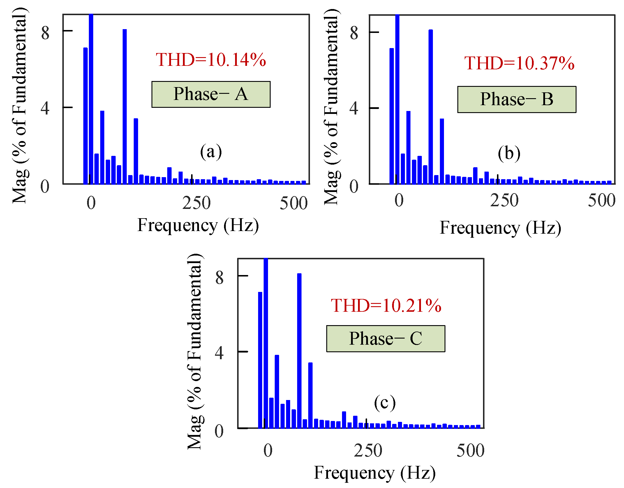
Figure 15.
Simulated three-phase output voltage waveforms of 16.67 Hz (m = 3) frequency conversion with motor load.
Figure 15.
Simulated three-phase output voltage waveforms of 16.67 Hz (m = 3) frequency conversion with motor load.

Figure 16.
Simulated three-phase output voltage waveforms of 12.5 Hz (m = 4) frequency conversion with motor load.
Figure 16.
Simulated three-phase output voltage waveforms of 12.5 Hz (m = 4) frequency conversion with motor load.
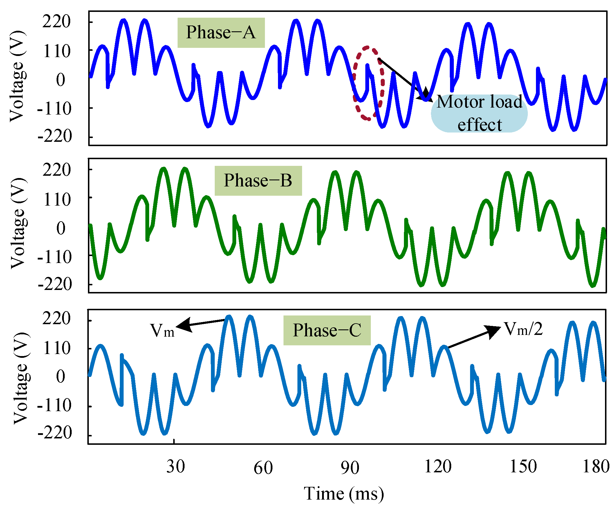
Figure 17.
Simulated three-phase output current waveforms of 16.67 Hz (m = 3) frequency conversion with motor load.
Figure 17.
Simulated three-phase output current waveforms of 16.67 Hz (m = 3) frequency conversion with motor load.

Figure 18.
Simulated three-phase output current waveforms of 12.5 Hz (m = 4) frequency conversion for motor load.
Figure 18.
Simulated three-phase output current waveforms of 12.5 Hz (m = 4) frequency conversion for motor load.
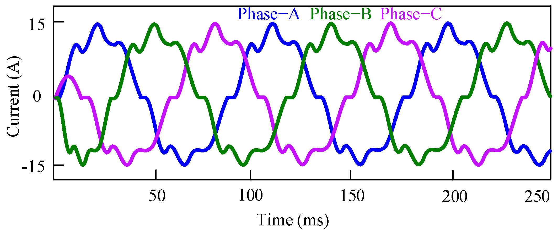
Figure 19.
Harmonic spectrums of the simulated three-phase load currents for 16.67 Hz (m = 3) frequency conversion with motor load.
Figure 19.
Harmonic spectrums of the simulated three-phase load currents for 16.67 Hz (m = 3) frequency conversion with motor load.
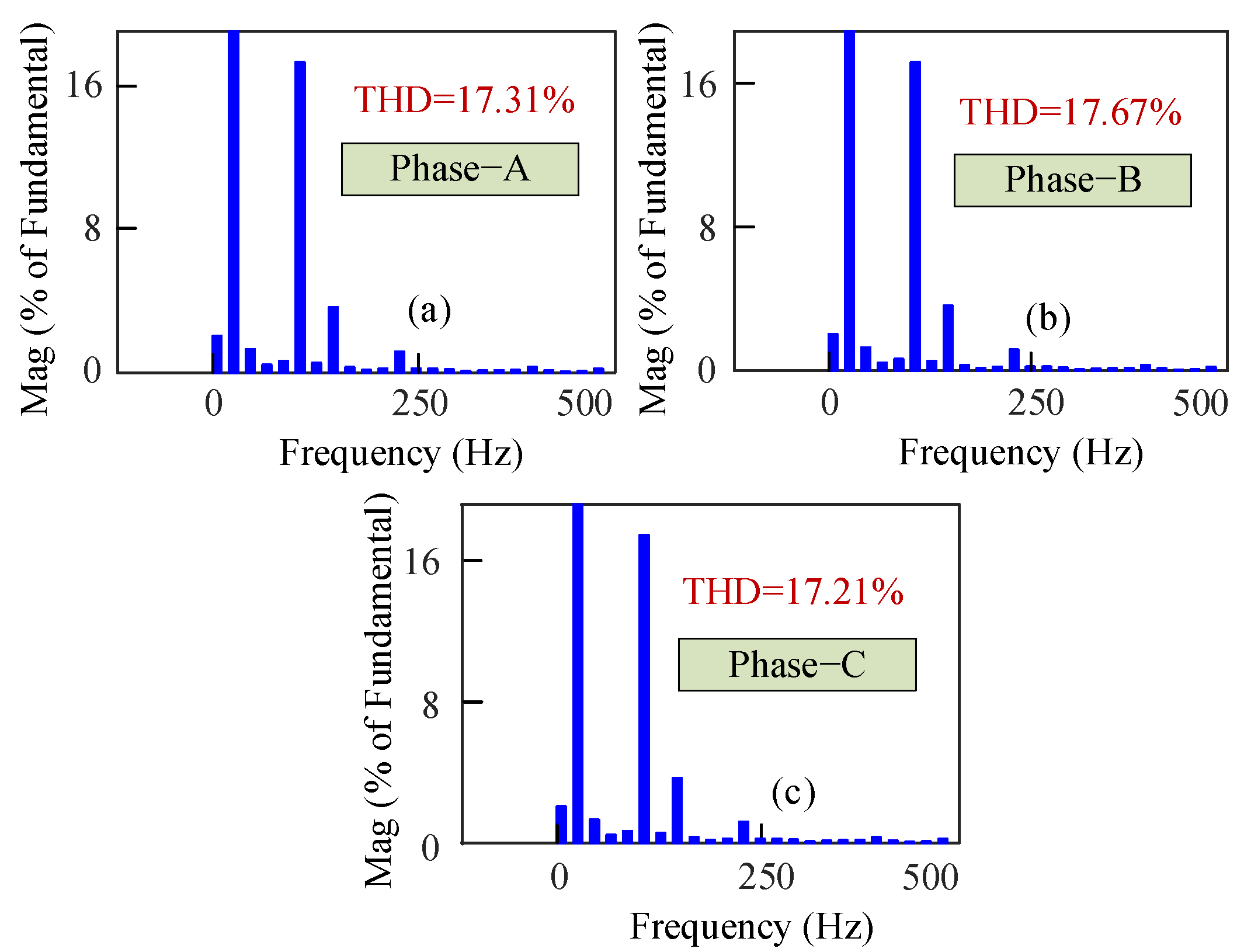
Figure 20.
Harmonic spectrums of the simulated three-phase load currents for 12.5 Hz (m = 3) frequency conversion with motor load.
Figure 20.
Harmonic spectrums of the simulated three-phase load currents for 12.5 Hz (m = 3) frequency conversion with motor load.

Figure 21.
Experimental test rig of the proposed AC/AC power converter.

Figure 22.
Experimental gate drive signals (5 V/div) of m = 3 (16.67 Hz output from 50 Hz input) frequency conversion for (a) phase-A, (b) phase-B, and (c) phase-C.
Figure 22.
Experimental gate drive signals (5 V/div) of m = 3 (16.67 Hz output from 50 Hz input) frequency conversion for (a) phase-A, (b) phase-B, and (c) phase-C.
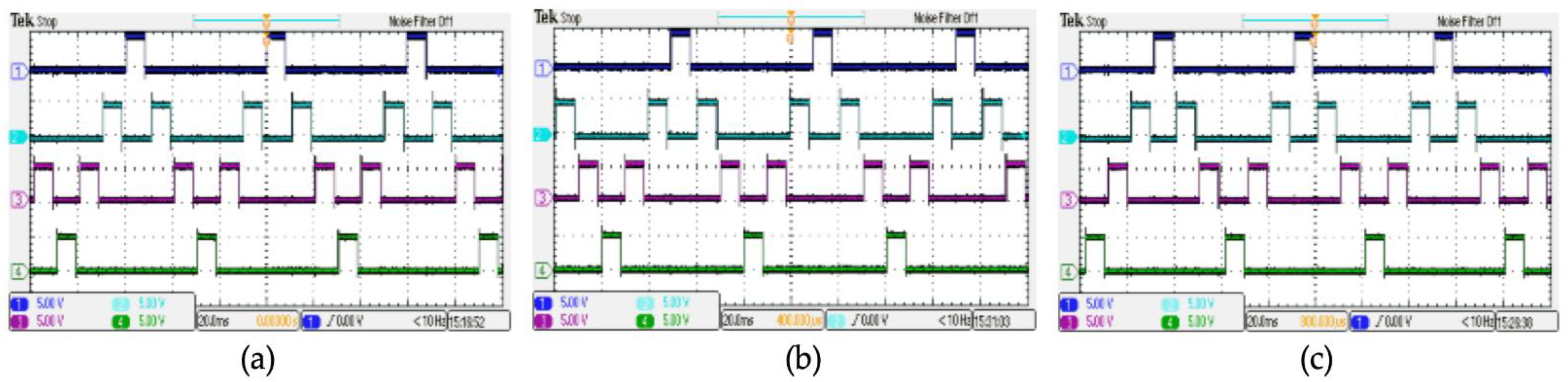
Figure 23.
Experimental gate drive signals (5 V/div) m = 4 (12.5 Hz output from 50 Hz input) frequency conversion for (a) phase-A, (b) phase-B, and (c) phase-C.
Figure 23.
Experimental gate drive signals (5 V/div) m = 4 (12.5 Hz output from 50 Hz input) frequency conversion for (a) phase-A, (b) phase-B, and (c) phase-C.
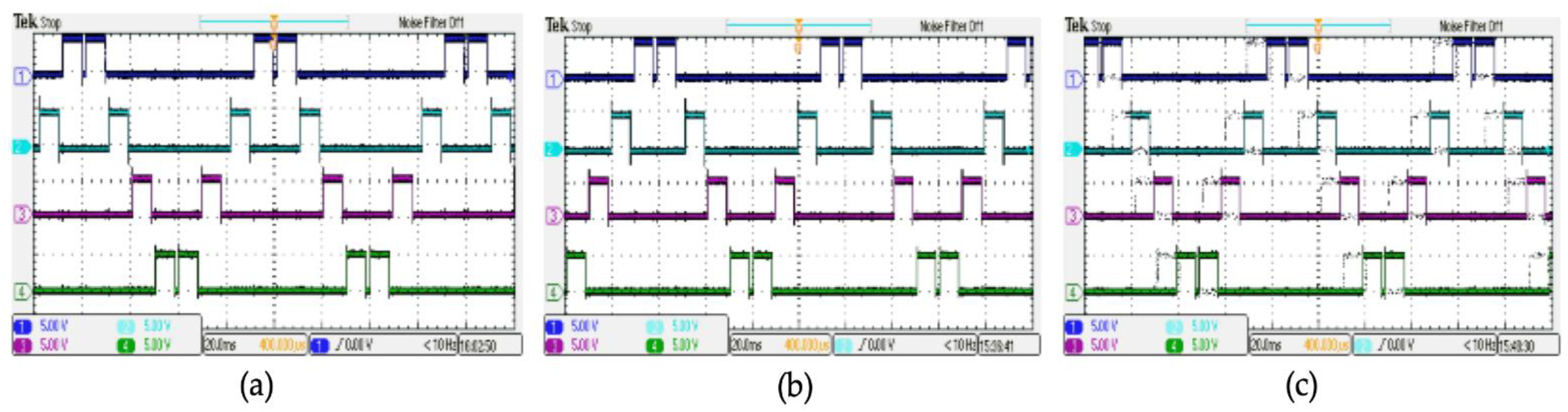
Figure 24.
Experimental output voltage (20 V/div) waveforms for (a) m = 3 (16.67 Hz output from 50 Hz input) and (b) m = 4 (12.5 Hz output from 50 Hz input) frequency conversion order with RL load.
Figure 24.
Experimental output voltage (20 V/div) waveforms for (a) m = 3 (16.67 Hz output from 50 Hz input) and (b) m = 4 (12.5 Hz output from 50 Hz input) frequency conversion order with RL load.

Figure 25.
Experimental output current (1 A/div) waveforms for (a) m = 3 (16.67 Hz output from 50 Hz input) and (b) m = 4 (12.5 Hz output from 50 Hz input) frequency conversion order with RL load.
Figure 25.
Experimental output current (1 A/div) waveforms for (a) m = 3 (16.67 Hz output from 50 Hz input) and (b) m = 4 (12.5 Hz output from 50 Hz input) frequency conversion order with RL load.

Figure 26.
Comparative analysis of filtered and unfiltered THDs among various AC/AC power converter topologies: Agarwal+2009 [39], Agarwal+2010 [40], Khedekar+2019 [41], Idris+2006 [42], Biswas+2017 [43], and Islam+2021 [44].

Table 1.
Switching states of the proposed AC/AC converter with corresponding frequency conversion order (m = 3 and m = 4).
Table 1.
Switching states of the proposed AC/AC converter with corresponding frequency conversion order (m = 3 and m = 4).
| Output Frequency (Hz) | Mode | Switching State | Output Voltage (V) | |||||||||||||
|---|---|---|---|---|---|---|---|---|---|---|---|---|---|---|---|---|
| Phase | Phase | |||||||||||||||
| A (0°) | B (120°) | C (240°) | A | B | C | |||||||||||
| S1 | S2 | S3 | S4 | S1 | S2 | S3 | S4 | S1 | S2 | S3 | S4 | |||||
| 16.67 Hz (m = 3) | 1 | 1 | 0 | 0 | 0 | 0 | 0 | 0 | 1 | 1 | 0 | 0 | 0 | +Vm/2 | +Vm/2 | −Vm |
| 2 | 0 | 0 | 0 | 1 | 1 | 0 | 0 | 0 | 1 | 0 | 0 | 0 | +Vm | −Vm/2 | −Vm/2 | |
| 3 | 1 | 0 | 0 | 0 | 1 | 0 | 0 | 0 | 0 | 0 | 0 | 1 | +Vm/2 | −Vm | +Vm/2 | |
| 1 | 1 | 0 | 0 | 0 | 0 | 0 | 0 | 1 | 1 | 0 | 0 | 0 | −Vm/2 | −Vm/2 | +Vm | |
| 2 | 0 | 0 | 0 | 1 | 1 | 0 | 0 | 0 | 1 | 0 | 0 | 0 | −Vm | +Vm/2 | +Vm/2 | |
| 3 | 1 | 0 | 0 | 0 | 1 | 0 | 0 | 0 | 0 | 0 | 0 | 1 | −Vm/2 | +Vm | −Vm/2 | |
| 12.5 Hz (m = 4) | 1 | 1 | 0 | 0 | 0 | 0 | 0 | 0 | 1 | 1 | 0 | 0 | 0 | +Vm/2 | +Vm/2 | −Vm |
| 2 | 0 | 0 | 0 | 1 | 1 | 0 | 0 | 0 | 1 | 0 | 0 | 0 | +Vm | −Vm/2 | −Vm/2 | |
| 4 | 0 | 0 | 1 | 0 | 1 | 0 | 0 | 0 | 0 | 0 | 0 | 1 | +Vm | −Vm | +Vm/2 | |
| 5 | 0 | 1 | 0 | 0 | 0 | 0 | 0 | 1 | 0 | 0 | 1 | 0 | +Vm/2 | −Vm | +Vm | |
| 6 | 0 | 1 | 0 | 0 | 0 | 0 | 1 | 0 | 0 | 1 | 0 | 0 | −Vm/2 | −Vm/2 | +Vm | |
| 7 | 0 | 0 | 1 | 0 | 0 | 1 | 0 | 0 | 0 | 1 | 0 | 0 | −Vm | +Vm/2 | +Vm/2 | |
| 8 | 0 | 0 | 0 | 1 | 0 | 1 | 0 | 0 | 0 | 0 | 1 | 0 | −Vm | +Vm | −Vm/2 | |
| 9 | 1 | 0 | 0 | 0 | 0 | 0 | 1 | 0 | 0 | 0 | 0 | 1 | −Vm/2 | +Vm | −Vm | |
Note: Switch ON = 1; Switch OFF = 0.
Table 2.
Simulation parameters of the proposed AC/AC power converter.
| Parameters | Values |
|---|---|
| Nominal power rating | 1.8 kVA |
| TRIAC (Two-thyristors equivalent) | Ron = 0.001 Ω, Vf = 0.8 V, Rs = 500 Ω, Cs = 250 nF |
| Supply voltage | 230 V |
| Supply frequency | 50 Hz |
| RL Load | R = 10 Ω, L = 5 mH |
| Induction motor (IM) | 1.5 hp |
| Stator winding of IM | Rst = 0.6 Ω, Lst = 0.34 mH |
| Rotor winding of IM | Rrt = 0.65 Ω, Lrt = 5.47 mH |
| Mutual Inductance of IM | Lm = 35.4 mH |
Table 3.
Parameters of experimental setup.
| Item | Specification |
|---|---|
| Input voltage (AC) | 230 V, 50 Hz |
| Multi-winding transformer | (28–14–0-14–28) V (1:4 winding) |
| TRIAC | BT136 |
| Opto-coupler | MOC3021, 4N35 |
| Microcontroller board | Arduino Mega (ATMega2560) |
| Load resistor | 10 Ω, 10 W |
| Load inductor | 5 mH |
Table 4.
Comparison between conventional and proposed power converter in terms of THD (m = 3).
| Harmonic Order | Conventional 3:1 (m = 3) | Proposed 3:1 (m = 3) | ||
|---|---|---|---|---|
| Fund. % of Output Current (A) (RL Load) | Fund. % of Output Current (A) (M. Load) | Fund. % of Output Current (A) (RL Load) | Fund. % of Output Current (A) (M. Load) | |
| DC Component | 0.00% | 3.22% | 0% | 1.10% |
| 1 | 100% | 100% | 100% | 100% |
| 2 | 0.01% | 4.23% | 0.04% | 0.66% |
| 3 | 30.89% | 37.68% | 0.00% | 0.07% |
| 4 | 0.01% | 4.09% | 0.03% | 0.45% |
| 5 | 28.45% | 40.07% | 12.42% | 16.21% |
| 6 | 0.06% | 5.54% | 0.01% | 0.43% |
| 7 | 8.73% | 12.46% | 3.65% | 3.80% |
| 8 | 0.01% | 2.97% | 0.00% | 0.16% |
| 9 | 0.04% | 3.95% | 0.00% | 0.01% |
| 10 | 0.01% | 2.96% | 0.00% | 0.12% |
| 11 | 2.14% | 2.93% | 0.92% | 1.12% |
| 12 | 0.01% | 3.52% | 0.00% | 0.17% |
| 13 | 1.24% | 0.75% | 0.54% | 0.39% |
| 14 | 0.01% | 0.97% | 0.00% | 0.07% |
| 15 | 0.03% | 1.80% | 0.00% | 0.00% |
| THD | 42.97% | 57.81% | 13.00% | 17.31% |
Note: Fund. = Fundamental; M. = Motor.
Table 5.
Comparison between conventional and proposed power converter in terms of THD (m = 4).
| Harmonic Order | Conventional 4:1 (m = 4) | Proposed 4:1 (m = 4) | ||
|---|---|---|---|---|
| Fund.% of Output Current (A) (RL Load) | Fund. % of Output Current (A) (M. Load) | Fund. % of Output Current (A) (RL Load) | Fund. % of Output Current (A) (M. Load) | |
| DC Component | 1.90% | 35.79% | 0.77% | 1.62% |
| 1 | 100% | 100% | 100% | 100% |
| 2 | 3.54% | 10.26% | 6.01% | 8.89% |
| 3 | 32.49% | 44.73% | 6.03% | 4.44% |
| 4 | 3.00% | 5.05% | 1.98% | 3.43% |
| 5 | 21.07% | 34.62% | 2.20% | 1.74% |
| 6 | 2.47% | 3.90% | 2.30% | 2.45% |
| 7 | 27.57% | 47.41% | 7.24% | 9.95% |
| 8 | 2.06% | 5.91% | 2.22% | 4.50% |
| 9 | 11.90% | 19.30% | 1.16% | 3.03% |
| 10 | 1.74% | 4.59% | 2.39% | 2.40% |
| 11 | 1.98% | 2.95% | 1.36% | 1.35% |
| 12 | 1.51% | 1.36% | 1.01% | 1.26% |
| 13 | 1.57% | 2.24% | 0.85% | 0.90% |
| 14 | 1.32% | 2.99% | 0.76% | 0.69% |
| 15 | 2.69% | 2.97% | 0.61% | 0.91% |
| THD | 49.82% | 78.09% | 12.00% | 16.35% |
Note: Fund. = Fundamental; M. = Motor.
Publisher’s Note: MDPI stays neutral with regard to jurisdictional claims in published maps and institutional affiliations. |
© 2022 by the authors. Licensee MDPI, Basel, Switzerland. This article is an open access article distributed under the terms and conditions of the Creative Commons Attribution (CC BY) license (https://creativecommons.org/licenses/by/4.0/).
Share and Cite
MDPI and ACS Style
Biswas, S.P.; Uddin, M.S.; Islam, M.R.; Mondal, S.; Nath, J. A Direct Single-Phase to Three-Phase AC/AC Power Converter. Electronics 2022, 11, 4213. https://doi.org/10.3390/electronics11244213
AMA Style
Biswas SP, Uddin MS, Islam MR, Mondal S, Nath J. A Direct Single-Phase to Three-Phase AC/AC Power Converter. Electronics. 2022; 11(24):4213. https://doi.org/10.3390/electronics11244213
Chicago/Turabian StyleBiswas, Shuvra Prokash, Md. Shihab Uddin, Md. Rabiul Islam, Sudipto Mondal, and Joysree Nath. 2022. "A Direct Single-Phase to Three-Phase AC/AC Power Converter" Electronics 11, no. 24: 4213. https://doi.org/10.3390/electronics11244213
Note that from the first issue of 2016, this journal uses article numbers instead of page numbers. See further details here.