1. Introduction
During the last two years, new solid-state power amplifiers with improved efficiency and performance readily available in the marketplace have been tested for high-power microwave applications [
1,
2].
Using semiconductor-based RF generators offers control perfection to any necessary degree in terms of the properties of the RF signal: frequency, phase, power level, modulation, and timing of the electromagnetic microwave field can be set and monitored for feedback at will. The basic idea is to turn this perfect control capability into a beneficial heat source in a solid-state RF-driven microwave oven [
3].
These developments present an opportunity to work with other ISM frequencies. Nevertheless, the lack of suitable feeding structures designs for this kind of source hinders fully exploiting the advantages offered by this technology because it must be used with conventional waveguide-based feeding circuits. A survey of patents of feeding structures for solid-state driven microwave ovens was conducted. A variety of feeding structures was identified, encompassing patch antennas [
4,
5], dipole antennas [
6], monopole antennas [
7,
8], and waveguides apertures [
9,
10,
11]. However, no reference to shielded slot antennas for solid-state driven microwave oven applicators was found.
The antenna presented in this paper aims at offering a solution to feed conventional microwave cavities with solid-state sources through compact TEM feeding structures capable of handling high power. In this way, it will be possible to improve the performance of both commercial and industrial microwave ovens while reducing the environmental impact of these devices.
Slot antennas have been widely used in high power microwave applications, being the most outstanding example, the slotted waveguide used in many radars [
12]. However, for communication purposes, printed slot antennas have more interesting features; hence, there is a lot of research effort devoted to them in the literature [
13,
14,
15,
16]. There is increased use of integrated patch antennas due to the need for size and cost reduction as well as integration with monolithic microwave integrated circuit (MMIC) devices [
17]. This paradigm shift that happened at the beginning of the century was limited to low-power applications. In high-power heating applications, tubes and waveguides had no opponent until now.
By combining slot and printed techniques, other kinds of antennas have been developed. Such is the case of cavity-backed antennas. As explained in the literature, the main feature of these antennas is the presence of a metallic plane to improve the performance of the main radiator. It can be used, for instance, to enhance the peak gain [
18], to improve the bandwidth [
19] or change the radiation pattern [
20].
The purpose of the present work is to use the antenna design techniques already available to create a feeding structure for a microwave applicator. In this case, even though the design is the same as an antenna, the focus has been set to achieve proper matching between the generator system and the applicator. Typical antenna parameters such as gain, or far-field radiation pattern make no sense in this case. The overall system efficiency (i.e., the ratio between the power delivered to the load and the one provided by the source) is driven by the return losses. Hence, this will be the main parameter considered to represent the behaviour of the feeding structure.
This paper is structured as follows:
Section 2 covers the methodology used to perform the complete parametric study and design.
Section 3 shows the results of the measurements carried out using a prototype manufactured according to the design developed in
Section 2.
Section 4 contains the discussion of the results. Lastly, some conclusions on both the design and the application are drawn in
Section 5.
2. Materials and Methods
2.1. Overview
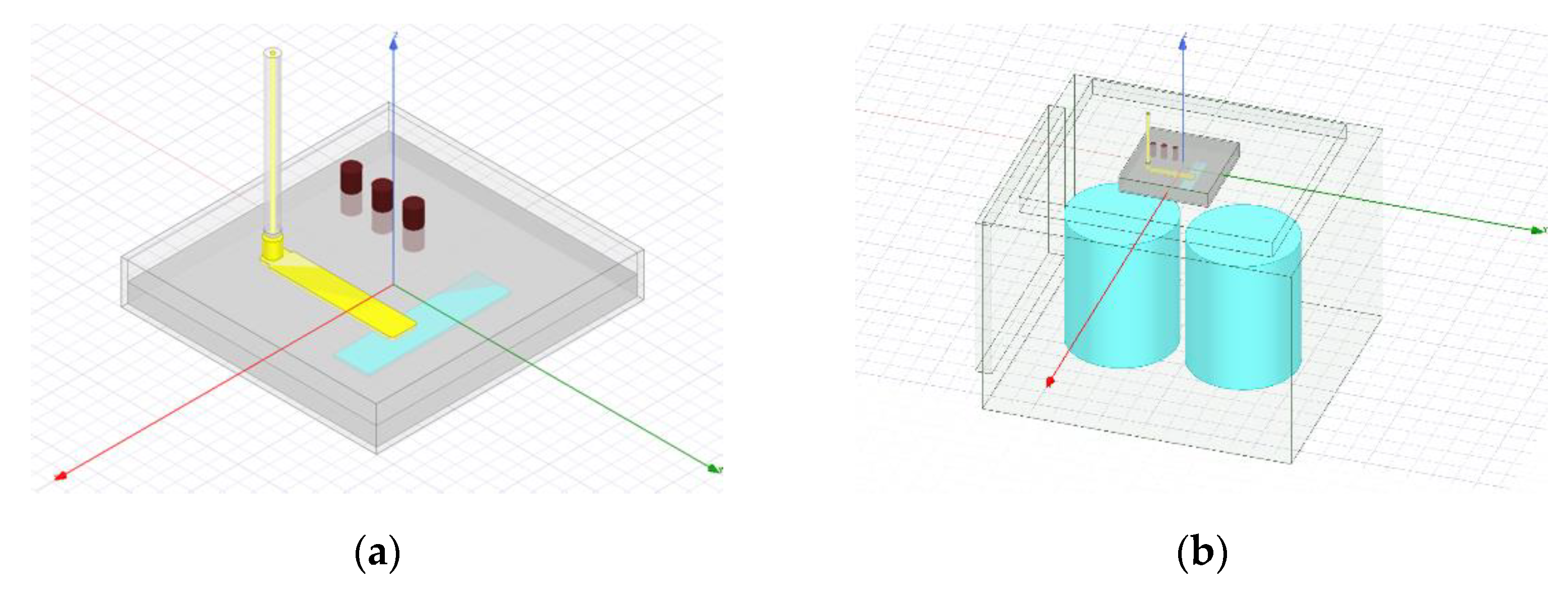
The proposed antenna has three main components: (1) a vertical coaxial-to-stripline transition with tapered matching elements, feeding an (2) asymmetric shielded stripline, which, in turn, feeds a (3) radiating slot (see
Figure 1a). The antenna is placed on the top of a standard commercial microwave oven, which is a combination of rectangular cavities.
Figure 1b shows the considered microwave cavity geometry and the load used for testing purposes (two 1-L containers filled with water).
The feeding structure is based on a slot antenna operating at 2.45 GHz, the ISM frequency most used in microwave heating applications. The design of the antenna consisted of five steps: (1) the slot antenna was designed on a ground plane without a cavity; this design led to the slot dimensions and the position of the feeding line; (2) due to the envisaged application, the stripline was shielded within a metallic box, and the slot design was modified to take into account the effect of the lateral walls; (3) a SIW (Substrate-integrated Waveguide) structure [
21] was added to suppress non-TEM modes arising in the shielding cavity; (4) the vertical coaxial-to-stripline transition was designed (including a matching network) to make this antenna easy to integrate into a microwave applicator, and (5) the slot dimensions were modified again to match the applicator impedance.
The initial design of the slot was carried out using standard antenna theory whereas the rest of the steps were done using the commercial Ansys HFSS full-wave simulator, based on the Finite Element Method (FEM). A prototype of the designed antenna was manufactured and measured in an anechoic chamber with the sole purpose of verifying that the coaxial-to-stripline transition is well adapted and the SIW structure suppresses the non-TEM modes.
Finally, to assess the proper performance of the feeding structure taking into account the effect of the applicator cavity, a 2-liter test was performed. This test is a standard method developed by the IMPI (International Microwave Power Institute) [
22] to check the actual efficiency of a microwave oven, consisting of heating 2 L of tempered water in two different containers for 122 s. Applying Equations (1) and (2), the value of the amount of power transmitted to the water is obtained (3).
E is the energy, P is the injected power, t is the duration of the test, m is the mass of the load, Ce is its specific heat, and ∆T is the temperature increase.
The two-liter test was conducted in two steps: (1) the return losses were simulated using ANSYS (ANSYS Multiphysics, ANSYS, Inc., Canonsburg, PA, USA) and measured in the laboratory, showing a good agreement, and (2) the absorbed power was obtained applying Equation (3).
The rest of
Section 2 describes the five design stages listed above, whereas the two-liter test is described in
Section 3, along with the rest of the results.
2.2. Slot Antenna Fed with a Stripline
A slot antenna consists of a narrow rectangular aperture on a ground plane of
L ×
W dimensions, where
L >> W. To have a good radiation performance, the length
L of the slot should be around half a wavelength (
L ≈
λ/2). At the same time, the width
W should be
W ≤ 0.1λ [
12]. Considering the 2.45 GHz working frequency, the first approach is a slot of
L = 60 mm and
W = 10 mm. Later, a study was performed to understand the effect of these two parameters (
Figure 2).
The slot antenna is fed using a stripline structure. The term stripline refers to a structure having a strip laying between two ground planes and parallel to them. Usually, the strip is placed at the same distance from each ground plane, but in this case, to simplify the manufacture of the antenna, the dielectric filling the space between both ground planes is split into two slabs with the exact dimensions. The strip is embedded in a slot drilled on the surface of one of them, leading to a slightly off-centre stripline structure [
23].
Considering the application envisaged for this antenna, the stripline used to feed it must be designed to support the propagation of high-power waves (in the order of 500 W). Therefore, a material with excellent dielectric and thermal properties (PTFE) was selected for the substrate. The separation between the ground planes and the stripline width was designed keeping in mind the power requirement, leading to a set-up consisting of two slabs of 6 mm height, allowing the stripline to be thick enough to support the required power. A parametric study of the strip width w was conducted to obtain a 50 Ω stripline, leading to a value of w = 8.34 mm.
The stripline-fed slot is a well-known antenna [
24]. The impedance matching of this kind of feed mainly depends on the distance between the feeding stripline and the centre of the slot [
25]. Once the strip and slot dimensions were defined, the position (distance to the slot centre) and the penetration over the slot width were the two parameters governing the impedance matching. A parametric analysis using HFSS showed that the best solution was achieved when the strip was 11 mm away from the slot centre and entirely covered the slot (see
Figure 3a).
2.3. Shielded Slot Antenna with SIW Structure
Due to the enclosed nature of the antenna (which is application-driven), it becomes a cavity, sharing the structure of the cavity-backed slot antenna [
26]. The two main design parameters for these antennas are the distance between the slot and the walls and between the upper and lower ground planes (i.e., the cavity height). A thorough parametric study was conducted to assess the sensitivity to these variables.
First, a high dependency on the distance to walls transverse to the slot was observed. This behaviour is because the standing wave pattern along the radiating slot strongly depends on this distance. The study showed that the effect of the separation between the two lateral walls transverse to the slot yields a significant variation within a narrow sweep (from 20 mm to 25 mm). The distance needed to tune the antenna at 2.45 GHz is 22 mm (which is close to λeff/4, a typical value for a resonator design).
A second parametric study was run to assess the distance’s effect to the closest parallel wall (that on the right of the slot in
Figure 3a). This effect is somehow equivalent to a displacement of the slot along the transverse (Y) direction and thus is similar to that of the slot width, W (i.e., basically affects the antenna matching).
Finally, the last parameter would be the height of the cavity. In this case, as the fed is designed as a stripline, the height has been defined to obtain a 50 Ω characteristic impedance in the line. A similar effect to that described above with the transverse lateral walls can also be observed on the strip. In this case, the distance of the strip to the closest wall is fixed by the slot and the position of the strip, leading to an asymmetric layout of the lateral walls parallel to the strip (see
Figure 3a). This asymmetry allows the appearance of high-order modes.
To cope with this issue, vias have been used to suppress them. A significant effort was devoted to understanding their behaviour [
27]. However, a new type of transmission line has been recently defined: Substrate-integrated Waveguides (SIW). This structure has propagation characteristics similar to the classical metallic rectangular waveguide [
28]. Moreover, most of the features of conventional waveguides such as the high-power handling capability, high-quality factor, and electrical and mechanical shielding with self-consistent property have been exhibited by the SIW. The diameter of the posts,
Vr in
Figure 3b, and the separation between them was obtained according to [
29], where a comprehensive study of SIW structures is presented.
2.4. Coaxial-to-Stripline Transition
This antenna has been designed to feed a microwave applicator. Therefore, the slot and the connector must be in opposite planes, making the injection of microwave power easier. For that purpose, a vertical transition is needed [
30].
A vertical coaxial-to-stripline transition usually needs two or three matching elements. In this case, a tapered strip and a cylinder were used to reduce the return losses. The design parameters for the tapered strip were the length, the width, and the distance to the closest wall (i.e., that on the left in
Figure 3a). In the case of the cylinder, its radius and its height are the parameters that drive the matching. The final dimensions of the matching elements were obtained using the HFSS simulation tool.
2.5. Antenna–Applicator Matching
When a resonant antenna such as the one discussed in the previous subsections is used to feed an empty resonant cavity, such as a commercial microwave oven applicator, there are several changes with regard to the antenna behaviour in the free space: (1) the resonant frequencies of the antenna are lower than those in the free space and (2) the resonances are also narrower. When the cavity is loaded, the resonances are wider (leading to larger band-width), the resonant frequencies are even lower, and the resonance level is higher due to the power absorbed by the load.
Thus, some changes to the antenna designed in the previous subsections must be made. According to the process described above in this section, an excellent approach to improving matching is modifying the slot width (
W) and length (
L), increasing
W from 10.7 to 11.2 mm and reducing
L from 49 to 46, which tunes this antenna to the loaded cavity.
Table 1 contains the final dimensions of the structure.
3. Results
The manufacturing process of the antenna was conducted from a mechanisation point of view (
Figure 4), with relatively thick components aiming to have a simple and economical design. Two aluminum plates were used for the shielding (with the corresponding bending); the strip was manufactured from a copper sheet and the transition from a cylindrical copper piece. Two 6 mm Teflon
® slabs were used as a dielectric filling, and metric screws served as metallic posts for the SIW. Four screws were used to secure the assembly and, finally, an N-connector was welded into the cylindrical transition.
The antenna was measured in an anechoic chamber (
Figure 5a), leading to radiation measurements shown in (
Figure 5b), where a large spot of a homogeneous electric field can be observed. These measurements also showed a resonant frequency at 2.35 GHz (
Figure 6), upholding the fact that the antenna needs to be designed with a higher resonant frequency to counter the cavity effect.
The antenna was also installed on top of a modified microwave oven (
Figure 7), and the S11 parameter was measured.
Figure 8 shows that both the model and the measure of the manufactured antenna have similar behaviour, although the simulated solution showed a smooth and symmetric line.
To conclude the measurements of the antenna integrated into the cavity, the IMPI 2-liter test was performed, as explained earlier in the paper. The constant parameters used for this test were (1) m(g) = 2000 g, (2) Ce = 4.1813 J/gK, and (3) t = 122 s.
The power was generated using a solid-state power amplifier (Generator Lab Kit, Leanfa Srl, Ruvo di Puglia, Bari, Italy) with an output power of 250 W and capable of measuring forward and reflected power during the test. After ten repetitions, the average results are shown in
Table 2. It can be seen that when significant power is introduced, the actual power absorption is higher than the S11 obtained in the measurements because of the effect of the load.
4. Discussion
A shielded slot antenna fed by an asymmetric stripline with a Substrate-integrated Waveguide (SIW) structure and N-connectorized was designed to work as a high-power feeding element for microwave applicators at 2.45 GHz.
A prototype was manufactured using simple elements, as can be seen in
Figure 4, and its return losses were measured in an anechoic chamber, as shown in
Figure 5, showing good agreement with the simulated values, thus confirming that the assembly process was successful. The deviation in
Figure 6 shows the challenge of manufacturing a TEM feeding structure with solid parts, where small air gaps can affect the tuned frequency.
Results in
Figure 8 show the agreement between the simulated model of the IMPI 2-L test set up and the measurement. Slight differences can be seen due to details that can be hardly included in the simulation. It is essential to underline that, after the feeding structure, the two most significant contributors to the impedance matching are the oven and the load.
Finally, the prototype was tested in a controlled environment according to standard procedures. The validation process (
Table 2) showed an efficiency higher than 80%, a good value for heating processes and a standard in the current microwave oven applicators. However, considering the total electric power consumption, solid-state generators overcome the electricity-to-radiofrequency transformation performance, resulting in a system with greater energy efficiency.
5. Conclusions
Given the results obtained, some essential details can be pointed out. One of them is the difficulty faced when manufacturing devices for microwave applications and obtaining results close to the design ones. For high-frequency applications such as the one presented in this paper, slight changes in the dimensions or air gaps produce important changes in the actual performance. Another important aspect is the variation between the modelling of a resonant cavity, focusing on the adaptation of a matching device, as the present antenna, and the actual performance. Other contour conditions and multiphysics modelling might be needed to improve that relationship, requiring more computing time and resources.


