
Near-Nyquist-Limit Optical Communication and Ranging Method Based on Waveform Matched PPM


School of Information and Electronics, Beijing Institute of Technology, Beijing 100081, China
*
Author to whom correspondence should be addressed.
Electronics 2022, 11(4), 565; https://doi.org/10.3390/electronics11040565
Submission received: 14 January 2022
/
Revised: 7 February 2022
/
Accepted: 9 February 2022
/
Published: 13 February 2022
(This article belongs to the Section Microwave and Wireless Communications)
Abstract
:Deep-space optical communication and ranging technologies have attracted much attention for satellite-to-earth and moon-to-earth exploration. In integrated communication and ranging scenarios, non-integer oversampling factors are employed to improve the ranging performance, which can cause accumulated timing errors. We propose a novel pulse position modulation (PPM) symbol decision method based on waveform matching to reduce the impact of accumulated timing errors near the Nyquist sampling limit. Simulation results demonstrate that the ranging accuracy can reach 2.6 and 0.52 mm at sampling rates of 625 Msps and 2.5 Gsps, respectively. The proposed symbol decision method has a gain of over 1.1 dB compared with the traditional method at the bit error rate (BER) of less than 10−6. The experimental results verify that this method can achieve high-precision measurements of distance and reliable transmission of information.
1. Introduction
Deep-space exploration is one of the most difficult and valuable types of space exploration. A total of 246 deep-space exploration activities have been carried out, but only 143 tasks were successful until 2020 [1]. Optical communication has the advantages of wide bandwidth, large communication capacity, strong anti-interception ability, and good confidentiality [2,3,4]. Differently from radio communication, optical communication does not require a frequency license; hence, is suitable for deep-space exploration missions [5,6,7]. A method capable of integrated communication and ranging is attractive to deep-space exploration.
In the past few decades, deep-space optical communication has aimed toward a high transmission rate and ranging accuracy. The National Institute of Information and Communications Technology (NICT) installed an optical communication terminal on the Japanese Engineering Test Satellite VI, which realized a data rate of 1 Mbps downlink from a Geostationary Earth Orbit (GEO) device to a ground (GND) receiving station between 1994 and 1996 [8]. In 2001, the European Space Agency (ESA) conducted the Semiconductor Laser Intersatellite Link Experiment and demonstrated a 50 Mbps optical link between GEO and Low Earth Orbit (LEO) terminals [9]. The Optical Inter-orbit Communications Engineering Test Satellite by NICT realized 50 Mbps communications between GEO-LEO satellites in 2006 [10]. The Near-Field Infrared Experiment by Missile Defense Agency and a German commercial SAR satellite named TerraSAR-X cooperated to achieve 5.6 Gbps cross-link experiments from 2007 to 2008 [11]. In 2011, Russia developed an onboard laser communication terminal which operated at 125 Mbps between the International Space Station and GND [12]. In 2013, the Lunar Laser Communication Demonstration designed by the National Aeronautics and Space Administration (NASA) realized a downlink transmission rate of 622 Mbps [13]. Micius by the Chinese Academy of Sciences achieved 5.12 Gbps communications between LEO and GND in 2016 [14]. From 2013 to 2019, ESA launched multiple satellites for the European Data Relay System, realizing a 1.8 Gbps laser link between LEO-GEO devices [15,16,17]. It will launch Engineering Test Satellite 9 by NICT in 2022 to study deep-space optical communication between GEO and GND at 10 Gbps [18]. The research trend of deep space laser communication is shown in Figure 1.
In the pulse position modulation (PPM) scheme, a symbol period is divided into several time slots, i.e., the information is transmitted by the position of a single pulse slot within the symbol [19]. The modulation methods of deep-space optical communication include on–off keying (OOK) control modulation, PPM, binary phase shift keying (BPSK) modulation, and differential phase shift keying (DPSK) modulation [14]. Taking advantage of its eminent power efficiency [20] and weak inter-symbol interference [21], PPM is suitable for future deep-space communication and ranging demands. The theoretical ranging accuracy depends on the slot rate, and higher ranging accuracy can be achieved at a higher slot rate. Restricted by the analog-to-digital converter (ADC) device sampling technology, it is necessary to process signals close to the Nyquist sampling limit to realize high-speed communication and high-precision ranging. The signal, meanwhile, needs to be operated on non-integer oversampling factors to improve the ranging performance. This process causes accumulated timing errors, so the pulse energy leaks to the adjacent slots. The bit error rate (BER) performance is degraded because of the leaked energy.
Tao proposed a method for simultaneous communication and ranging using dual-pulse interval modulation (DPIM) [22]. The method improves the reliability of system communication and has a simple hardware structure. However, it does not address the relationship between and ranging accuracy. The communication rate was extremely low: 6.25 kbps was realized. The ranging accuracy was only about 2 cm in a laboratory environment, which is not enough for deep space exploration. The performance of this method is degraded near the Nyquist sampling limit.
An integrated method of optical communication and ranging is described, and a PPM symbol decision method based on waveform matching is proposed to reduce the impact of PPM signal energy leakage near the Nyquist sampling limit. A technical approach to high-precision ranging and reliable communication is presented for the integrated task for deep-space optical measurement and control.
The rest of this paper is organized as follows. In Section 2, the system structure and ranging method are described. In Section 3, the waveform matching algorithm is proposed. In Section 4, simulation results are, presented and discussed. In Section 5, the experimental platform is designed, and the results are analyzed. Finally, concluding remarks are provided in Section 6.
2. Deep-Space Optical Communication and Ranging Method Based on PPM
2.1. System Structure
The integrated system for deep-space optical measurement and control contains the ground terminal and the space terminal, as shown in Figure 2. The electronic control unit controls the entire terminal: it sends and receives the communication data. The modem module processes electrical signals, including sampling, modulation/demodulation, etc. The optical module processes optical signals, realizing the mutual conversions between electrical and optical signals.
The downlink refers to the transmission direction of the space terminal to the ground terminal. The modulation module operates framing, encoding, scrambling, modulating, and PPM symbol mapping of the control instructions and communication data issued by the electronic control unit in the space terminal. The laser diode transmitter converts electrical signals into optical signals. Then optical signals are transmitted through an optical antenna, i.e., an optical telescope. The optical antenna on the ground terminal receives downlink optical signals transmitted through free space. As downlink optical signals are extremely weak, a superconducting nanowire single-photon detector (SNSPD) [23,24] is used to detect a single photon. The demodulation module conducts sampling, demodulation, and decoding of baseband signals. The field programmable gate array (FPGA) processes and transmits ranging information and communication data to the electronic control unit in the modem module.
The uplink refers to the transmission direction of the ground terminal to the space terminal. The difference between an uplink and a downlink is that the space terminal uses a lightweight single-photon avalanche diode (SPAD) [25,26,27] for photon detection, limited by the volume and weight of the payload.
The L-ary pulse position modulation (L-PPM) symbol [28] can be expressed as:
where T is the symbol period and L indicates the length of slots within a symbol. indicates the location of the pulse. The rect(t) is defined as:
As SPAD and SNSPD cannot detect the signal within their dead time [29,30,31], inserting the guard time slot into the signal and receiving it by the detector array are applied to solve the problem [32,33]. The former can be realized by programming but reduces communication efficiency, whereas the latter increases hardware complexity and power consumption. Therefore, the method of inserting guard slots is applied to solve this problem of SPAD. Hence, there is in (1) for the uplink signal, and the length of the guard slots is . An array comprising multiple SNSPDs is employed for the downlink signal; hence, there is no need to insert guard slots, , for the downlink signal.
2.2. Ranging Method
The essence of ranging is the measurement of time-of-flight (TOF). The measurement variables of time involved in the ranging method are shown in Figure 3. The transmission time of the signal in free space can be obtained by recording the sending time and receiving time. Due to non-integer oversampling ratios, the frequency of TX Clk is not equal to that of RX. It is impossible to add or subtract the sending time recorded by TX Clk and the receiving time recorded by RX Clk because the time starting points of the two are difficult to align. To solve this problem, a self-looping link is designed for self-transmitting and self-receiving, which can realize the record of the sending time by RX Clk. In addition, the unmeasured inherent delay in the system can be eliminated with the help of the self-looping link. The detailed description is as follows.
The ground terminal generates an uplink signal at time and sends the signal after the transmission delay . The ground terminal receives the signal through the cable delay and the reception delay of the self-looping link at time . The receiving time of the downlink signal is recorded after a processing delay .
The space terminal generates a downlink signal at time , and sends the signal after the transmission delay . The space terminal receives the signal through the cable delay and the reception delay of the self-looping link at time . The receiving time of the downlink signal is recorded after a processing delay . The transmission time of uplink and downlink signals in free space is .
Thus, the distance between the space terminal and the ground terminal is given by:
where is the propagation speed of light in vacuum.
The basis of accurate ranging is to achieve accurate time measurement, i.e., the measurement accuracy of , , and determines the accuracy of ranging. Assume the time difference between the signal arrival time and the sampling time interval is , as shown in Figure 4. , where denotes sampling rate. The phase of a slot is quantized and indicates the left phase of the last slot of the previous frame. The target variable of time that needs to be measured is . The signal is sampled at a frequency that is relatively prime for the slot rate. fluctuates within the sampling time period ; hence, there are slight fluctuations in the synchronization process of the signal. Higher ranging accuracy can be obtained by estimating these fluctuations more accurately.
The time difference () is given by:
where represents the starting phase of the frame obtained by the signal synchronization algorithm, which is the phase corresponding to . K denotes the phase quantization depth of a slot, and indicates the slot rate. It is shown that the timing accuracy is determined by K and with the same .
As shown in Figure 4, the sum of the starting phase and the left phase is the code numerically controlled oscillator (), i.e., , where is determined by the signal synchronization algorithm. The starting phase of the hth frame is expressed as:
where and denotes the set of integers. The left phase is given by:
where is the number of slots setting in a frame, and is the number of sampling points in a frame calculated by and oversampling factors.
3. PPM Symbol Decision Algorithm Based on Waveform Matching
The position of the pulse slot within the symbol reflects the information carried by the PPM symbol. With the digital signal sampled and discretized by ADC, the estimated pulse slot position of PPM symbol can be described as:
where is the number of sampling points in a slot. . For integrated communication and ranging scenarios, the bit error performance of (12) is degraded due to the non-integer oversampling ratio, especially near the Nyquist sampling limit.
We propose a L-PPM symbol decision method based on waveform matching to solve the energy leakage problem at near-Nyquist-limit. This method accumulates adjacent sampling points to reduce pulse energy loss, as in (12). The maximum point of the accumulated signal is applied to find the pulse slot sampling points and neighboring points. Then the method matches those points in the pulse waveform expression, which is obtained and modeled by the actual situation. The pulses have different shapes of different systems. The ideal shape is a rectangle expressed by (2). In high-speed conditions, the pulse behaves as an approximately quadratic function when the system bandwidth is insufficient, since the PPM signal is an ultra-wideband signal. The pulse output by SNSPD shows a rapid rise followed by an exponential decay, as shown in Figure 5. Traditional interpolation algorithms such as the Gardner method can only achieve linear interpolation when the oversampling rate is near the Nyquist sampling limit, which differs from the waveform characteristics of the pulse signal. Therefore, the pulse waveform is modeled, and the sampled data are matched to the pulse waveform model to reconstruct the best sampling point and position of the pulse. The pseudo-code of the proposed method is described in Algorithm 1.
| Algorithm 1 Waveform matched PPM symbol decision algorithm. |
| Input: received signal samples Initialization:, PPM pulse slot time-domain model
|
4. Simulation Results
The indicators for evaluating the performance of the integrated system are ranging accuracy and communication reliability. The ranging accuracy is evaluated by the root mean square error (RMSE) . Furthermore, bit error performance is employed to assess communication reliability.
4.1. Ranging Accuracy
Two scenarios near the Nyquist sampling limit were simulated. They were and , respectively. Four other scenarios of higher oversampling rates were employed as the comparison. The simulation results are shown in Figure 6.
It can be seen that the improved speed of ranging accuracy gradually slows down with the increase in , where is the bit energy and is the noise power spectral density. At the same sampling rate (), a higher slot rate () and a lower are achieved. With near the Nyquist sampling limit, Gsps and Msps can reach 0.52 and 2.4 mm, respectively, when is 18 dB. The simulation results demonstrate that it is necessary to increase or slot rate to obtain higher ranging accuracy.
4.2. Bit Error Rate
The proposed method was compared with the traditional method shown in (12) via simulation. We employed RS(255,223) code as the forward error correction approach. This code is suggested by the Consultative Committee for Space Data Systems (CCSDS). A sampling rate of Gsps, as shown in Figure 7, was obtained. Compared with the other two scenarios, about 1.3 dB loss is inevitable for 1.24416 Gslot/s when the bit error rate is 10−6 by (12). The reason for this is that timing errors have a greater impact on the lower oversampling ratio scenario. It can be seen that the BER performances of the traditional method and the proposed method are basically the same far from the Nyquist sampling limit, but a gain of around 1.1 dB is achieved near the limit for the proposed method. The proposed algorithm is more advantageous than the traditional algorithm when it is near the Nyquist sampling limit. The results with a sampling rate of Msps are similar to that of Gsps.
5. Experimental Results
In order to verify the feasibility of the proposed method, we have built a hardware platform for real world tests. A diagram and a photograph of the hardware platform are given in Figure 8. ② is the initiator of the system. The uplink PPM electrical signal sent by the ground terminal is converted into a 1550 nm laser signal by the laser diode transmitter placed in the laser source modulation module. The laser signal is transmitted in the optical fiber and detected into an electrical signal by SPAD. The electrical signal is sent to the space terminal, which samples the uplink signal and performs digital signal processing to receive communication and ranging information. The frequency reference provides a GPS timing clock and time information for the ground terminal and the space terminal. Similarly, the downlink PPM signal sent by the space terminal is converted into the laser signal, which is transmitted in optical fiber and detected by SNSPD array. The ground terminal collects the downlink PPM signal with ADC and processes the sampled digital signal to obtain communication and ranging information.
The variable optical attenuator FVA-600 is applied to simulate the atmospheric attenuation. The atmospheric attenuation [34] can be calculated using
where is an atmospheric attenuation coefficient, V is visibility in kilometers, and l is the transmission distance in kilometers. In the experiment, the emission power of the laser was 10 dBm. We set the attenuation value to 100 dB. The equivalent transmission distance exceeds 100,654 km when V is greater than 750 km.
A small number of control commands were transmitted through the uplink, for deep-space exploration spacecraft, and a large amount of research data obtained by the probe were transmitted through the downlink. Therefore, the demand for downlink communication speed was much higher than that for uplink communication speed. The hardware system depicted in Figure 8 applied Mslot/s for the uplink and Gslot/s for the downlink, respectively, with an oversampling factor near the Nyquist limit.
The video transmission results are given in Figure 9, which displays the local video (left) and the received video (right). Real-time video transmission can be carried out between the two terminals to visually demonstrate the communication quality.
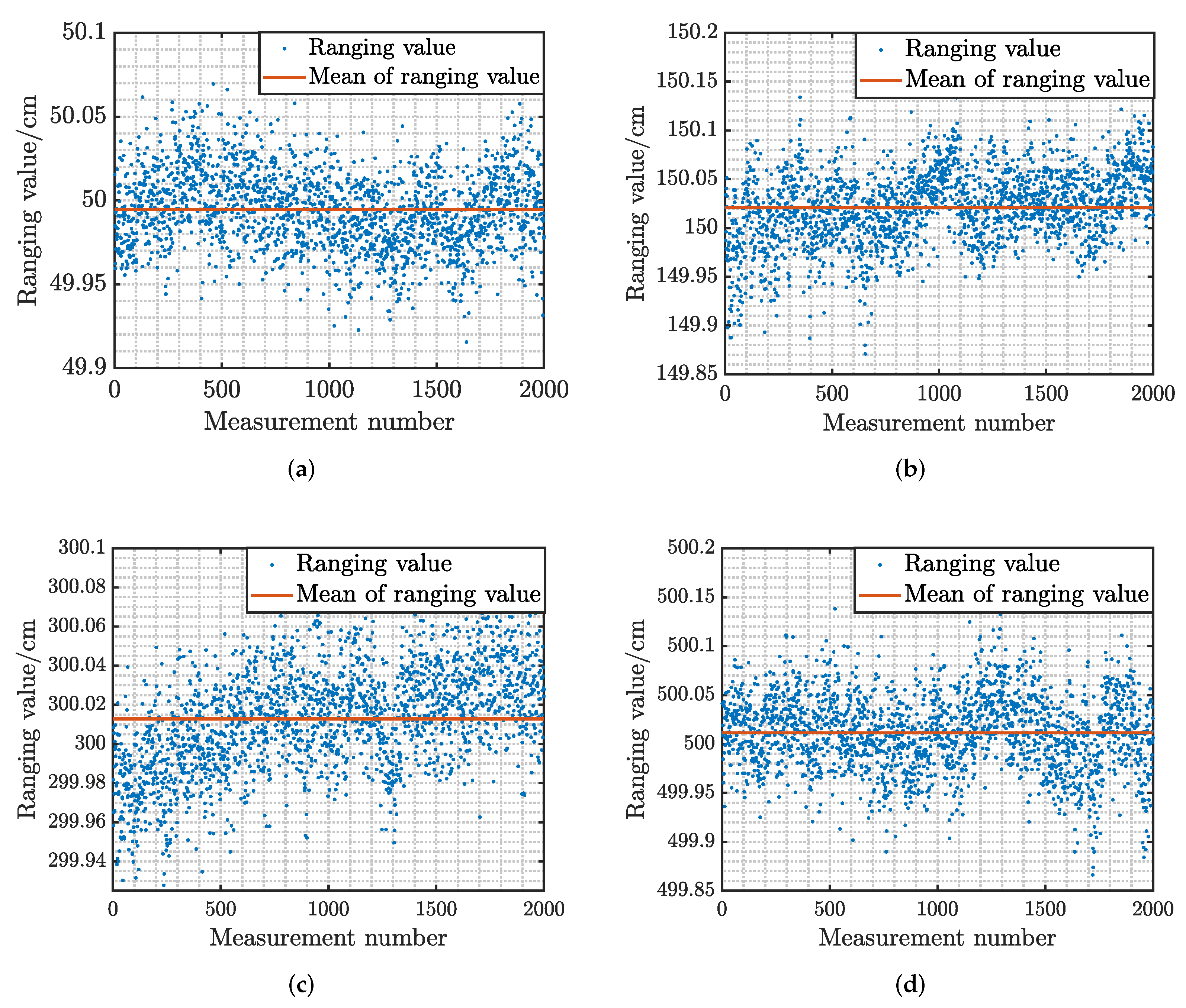
The ranging performances of the system at different distances were tested. Four distance scenarios were selected for statistics, 0.5, 1.5, 3, and 5 m, respectively. The ranging results are presented in Figure 10. As shown, a blue dot resulted from a single ranging, and the red line is the average of total single ranging results. The statistics for the ranging results are displayed in Table 1. The RMSE() was calculated with the total data observed. It can be seen that the RMSE() was less than 0.4 mm at each set distance. Some experimental data show low frequency variation due to instability of the frequency reference module.
6. Conclusions
A method of integrated optical communication and ranging based on PPM was presented. The ranging accuracy can be improved with a higher slot rate at the same sampling rate. In particular, a novel PPM symbol decision method based on waveform matching was proposed to solve the problem of slot energy leakage near the Nyquist sampling limit. A gain of around 1.1 dB in bit error performance is achieved by the proposed method compared with the traditional method. Reliable optical communication and high accuracy of range measurements are obtained at the same time by the experimental hardware platform. Real-time video transmission was demonstrated, and the ranging accuracy was higher than 0.4 mm.
Author Contributions
Formal analysis, C.H., Y.L., J.L. and X.B.; funding acquisition, J.A.; writing—original draft, C.H.; writing—review and editing, C.H. and Y.L. All authors have read and agreed to the published version of the manuscript.
Funding
This research was funded by National Scientific Foundation of China under grant 62001030.
Conflicts of Interest
The authors declare no conflict of interest.
References
- Yu, G. Application and trend of model-based systems engineering methods for deep space exploration mission. J. Deep. Space Explor. 2021, 8, 407–415. [Google Scholar]
- Malik, S.; Sahu, P.K. Performance analysis of free space optical communication system using different modulation schemes over weak to strong atmospheric turbulence channels. In Optical and Wireless Technologies; Springer: Berlin/Heidelberg, Germany, 2020; Volume 546, pp. 387–399. [Google Scholar]
- Chen, J.; Huang, Y.; Cai, R.; Zheng, A.; Yu, Z.; Wang, T.; Liu, Z.; Gao, S. Free-space communication turbulence compensation by optical phase conjugation. IEEE Photonics J. 2020, 12, 1–11. [Google Scholar] [CrossRef]
- Li, R.; Chen, T.; Fan, L.; Dang, A. Performance analysis of a multiuser dual-hop amplify-and-forward relay system with FSO/RF links. J. Opt. Commun. Netw. 2019, 11, 362–370. [Google Scholar] [CrossRef]
- Toyoshima, M. Recent trends in space laser communications for small satellites and constellations. J. Light. Technol. 2020, 39, 693–699. [Google Scholar] [CrossRef]
- Wu, W.; Chen, M.; Zhang, Z.; Liu, X.; Dong, Y. Overview of deep space laser communication. Sci. China Inf. Sci. 2018, 61, 1–12. [Google Scholar] [CrossRef]
- An, J.; Zhang, Y.; Gao, X.; Yang, K. Energy-Efficient Base Station Association and Beamforming for Multi-Cell Multiuser Systems. IEEE Trans. Wirel. Commun. 2020, 19, 2841–2854. [Google Scholar] [CrossRef]
- Araki, K.; Arimoto, Y.; Shikatani, M.; Toyoda, M.; Toyoshima, M.; Takahashi, T.; Kanda, S.; Shiratama, K. Performance evaluation of laser communication equipment onboard the ETS-VI satellite. In Free-Space Laser Communication Technologies VIII. International Society for Optics and Photonics; SPIE: Bellingham, WA, USA, 1996; Volume 2699, pp. 52–59. [Google Scholar]
- Tolker-Nielsen, T.; Oppenhauser, G. In-orbit test result of an operational optical intersatellite link between ARTEMIS and SPOT4, SILEX. In Free-Space Laser Communication Technologies XIV. International Society for Optics and Photonics; SPIE: Bellingham, WA, USA, 2002; Volume 4635, pp. 1–15. [Google Scholar]
- Jono, T.; Takayama, Y.; Shiratama, K.; Mase, I.; Demelenne, B.; Sodnik, Z.; Bird, A.; Toyoshima, M.; Kunimori, H.; Giggenbach, D.; et al. Overview of the inter-orbit and the orbit-to-ground laser communication demonstration by OICETS. In Free-Space Laser Communication Technologies XIX and Atmospheric Propagation of Electromagnetic Waves. International Society for Optics and Photonics; SPIE: Bellingham, WA, USA, 2007; Volume 6457, p. 645702. [Google Scholar]
- Fields, R.; Lunde, C.; Wong, R.; Wicker, J.; Kozlowski, D.; Jordan, J.; Hansen, B.; Muehlnikel, G.; Scheel, W.; Sterr, U.; et al. NFIRE-to-TerraSAR-X laser communication results: Satellite pointing, disturbances, and other attributes consistent with successful performance. In Sensors and Systems for Space Applications III. International Society for Optics and Photonics; SPIE: Bellingham, WA, USA, 2009; Volume 7330, p. 73300Q. [Google Scholar]
- Grigoryev, V.; Kovalev, V.; Shargorodskiy, V.; Sumerin, V. High-bit-rate laser space communication technology and results of on-board experiment. In Proceedings of the International Conference on Space Optics, Kobe, Japan, 7–9 May 2014; Volume 7685, pp. 1–3. [Google Scholar]
- Boroson, D.M.; Robinson, B.S.; Murphy, D.V. Overview and results of the lunar laser communication demonstration. In Free-Space Laser Communication and Atmospheric Propagation XXVI. International Society for Optics and Photonics; SPIE: Bellingham, WA, USA, 2014; Volume 8971, p. 89710S. [Google Scholar]
- Chen, W.; Sun, J.; Hou, X.; Zhu, R.; Hou, P.; Yang, Y.; Gao, M.; Lei, L.; Xie, K.; Huang, M.; et al. 5.12 Gbps optical communication link between LEO satellite and ground station. In Proceedings of the 2017 IEEE International Conference on Space Optical Systems and Applications (ICSOS), Naha, Japan, 14–16 November 2017; pp. 260–263. [Google Scholar]
- Hauschildt, H.; Garat, F.; Greus, H.; Kably, K.; Lejault, J.; Ludwig Moeller, H.; Murrell, A.; Perdigues, J.; Witting, M. European data relay system–one year to go! In Proceedings of the International Conference on Space Optical Systems and Applications (ICSOS). Kobe, Japan, 7–9 May 2014; Volume 2014. [Google Scholar]
- Calzolaio, D.; Curreli, F.; Duncan, J.; Moorhouse, A.; Perez, G.; Voegt, S. EDRS-C—The second node of the European data relay system is in orbit. Acta Astronaut. 2020, 177, 537–544. [Google Scholar] [CrossRef]
- Hauschildt, H.; le Gallou, N.; Mezzasoma, S.; Moeller, H.L.; Armengol, J.P.; Witting, M.; Herrmann, J.; Carmona, C. Global quasi-real-time-services back to Europe: EDRS Global. In Proceedings of the International Conference on Space Optics—ICSO 2018. International Society for Optics and Photonics, Chania, Greece, 12 October 2018; Volume 11180, p. 111800X. [Google Scholar]
- Munemasa, Y.; Saito, Y.; Carrasco-Casado, A.; Kolev, D.R.; Trinh, P.V.; Takenaka, H.; Suzuki, K. Advanced demonstration plans of high-speed laser communication “HICALI” mission onboard the engineering test satellite 9. In Proceedings of the Advances in Communications Satellite Systems. Proceedings of the 37th International Communications Satellite Systems Conference (ICSSC-2019); Okinawa, Japan, 29 October–1 November 2019, pp. 1–7.
- Maalej, M.; Besbes, H. Performance of free space optical communication system based on M-ary PPM modulation over double generalized gamma channel. China Commun. 2020, 17, 19–30. [Google Scholar] [CrossRef]
- Xu, G. Error performance of deep space optical communication with M-ary pulse position modulation over coronal turbulence channels. Opt. express 2019, 27, 13344–13356. [Google Scholar] [CrossRef]
- Noshad, M.; Brandt-Pearce, M. Expurgated PPM using symmetric balanced incomplete block designs. IEEE Commun. Lett. 2012, 16, 968–971. [Google Scholar] [CrossRef]
- Tao, M.; Guan, J.; Peng, T.; Li, S.; Yu, S.; Song, J.; Song, Z.; Gao, L.; Gao, F. Simultaneous realization of laser ranging and communication based on dual-pulse interval modulation. IEEE Trans. Instrum. Meas. 2021, 70, 1–10. [Google Scholar] [CrossRef]
- You, L. Superconducting nanowire single-photon detectors for quantum information. Nanophotonics 2020, 9, 2673–2692. [Google Scholar] [CrossRef]
- Li, X.; Tan, J.; Zheng, K.; Zhang, L.; Zhang, L.; He, W.; Huang, P.; Li, H.; Zhang, B.; Chen, Q.; et al. Enhanced photon communication through Bayesian estimation with an SNSPD array. Photonics Res. 2020, 8, 637–641. [Google Scholar] [CrossRef]
- Sarbazi, E.; Safari, M.; Haas, H. The bit error performance and information transfer rate of SPAD array optical receivers. IEEE Trans. Commun. 2020, 68, 5689–5705. [Google Scholar] [CrossRef]
- Koziy, A.A.; Losev, A.; Zavodilenko, V.V.; Kurochkin, Y.V.; Gorbatsevich, A.A. Modern methods of detecting single photons and their application in quantum communications. Quantum Electron. 2021, 51, 655. [Google Scholar] [CrossRef]
- Ren, X.; Xu, B.; Fei, Q.; Liang, Y.; Ge, J.; Wang, X.; Huang, K.; Yan, M.; Zeng, H. Single-photon counting laser ranging with optical frequency combs. IEEE Photonics Technol. Lett. 2020, 33, 27–30. [Google Scholar] [CrossRef]
- Djordjevic, I.B. Multidimensional pulse-position coded-modulation for deep-space optical communication. IEEE Photonics Technol. Lett. 2011, 23, 1355–1357. [Google Scholar] [CrossRef]
- Kosman, J.; Moore, K.; Haas, H.; Henderson, R.K. Distortion losses of high-speed single-photon avalanche diode optical receivers approaching quantum sensitivity. Philos. Trans. R. Soc. A 2020, 378, 20190194. [Google Scholar] [CrossRef] [Green Version]
- Meng, X.; Cunningham, D.G.; White, I.H.; Penty, R.V. SPAD-Array contention signal and noise model suitable for multilevel modulation schemes with signal processing. IEEE Access 2021, 9, 48483–48500. [Google Scholar] [CrossRef]
- Li, B.; Liu, Y.; Tong, S.; Zhang, L.; Yao, H. BER analysis of a deep space optical communication system based on SNSPD over double generalized gamma channel. IEEE Photonics J. 2018, 10, 1–7. [Google Scholar] [CrossRef]
- Ivanov, H.; Leitgeb, E.; Pezzei, P.; Freiberger, G. Experimental characterization of SNSPD receiver technology for deep space FSO under laboratory testbed conditions. Optik 2019, 195, 163101. [Google Scholar] [CrossRef]
- Wen, G.; Huang, J.; Dai, J.; Zhang, L.; Wang, J. Performance analysis optimization and experimental verification of a photon-counting communication system based on non-photon-number-resolution detectors. Opt. Commun. 2020, 468, 125771. [Google Scholar] [CrossRef]
- Handura, M.; Ndjavera, K.; Nyirenda, C.; Olwal, T. Determining the feasibility of free space optical communication in Namibia. Opt. Commun. 2016, 366, 425–430. [Google Scholar] [CrossRef]

Figure 2.
Structure of the integrated system for deep-space optical measurement and control.

Figure 3.
Time relationships for ranging.

Figure 4.
Signal arrival time.
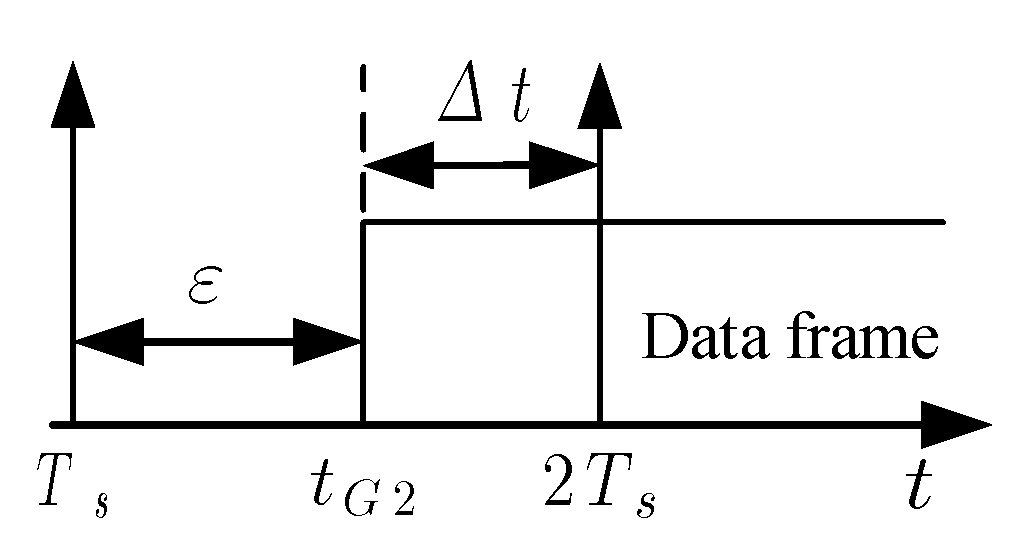
Figure 5.
SNSPD response pulse waveform. denotes the time-domain model of the waveform. indicates the discrete signal.
Figure 5.
SNSPD response pulse waveform. denotes the time-domain model of the waveform. indicates the discrete signal.

Figure 6.
Ranging accuracy () simulation results.

Figure 7.
BER simulation results ( Gsps).
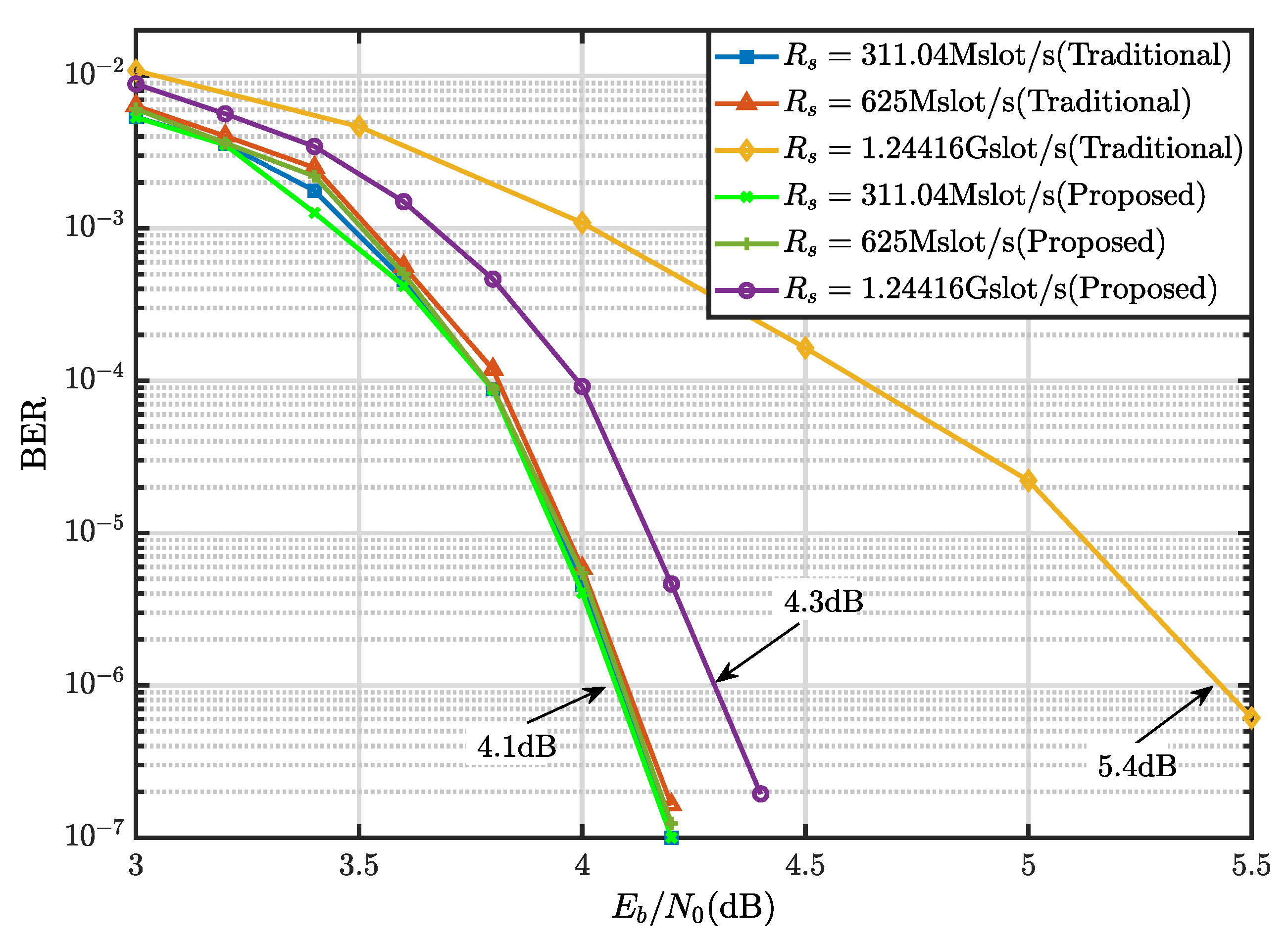
Figure 8.
Structure of the hardware platform: (a) Topology of the hardware platform. (b) Photograph of the hardware platform.
Figure 8.
Structure of the hardware platform: (a) Topology of the hardware platform. (b) Photograph of the hardware platform.
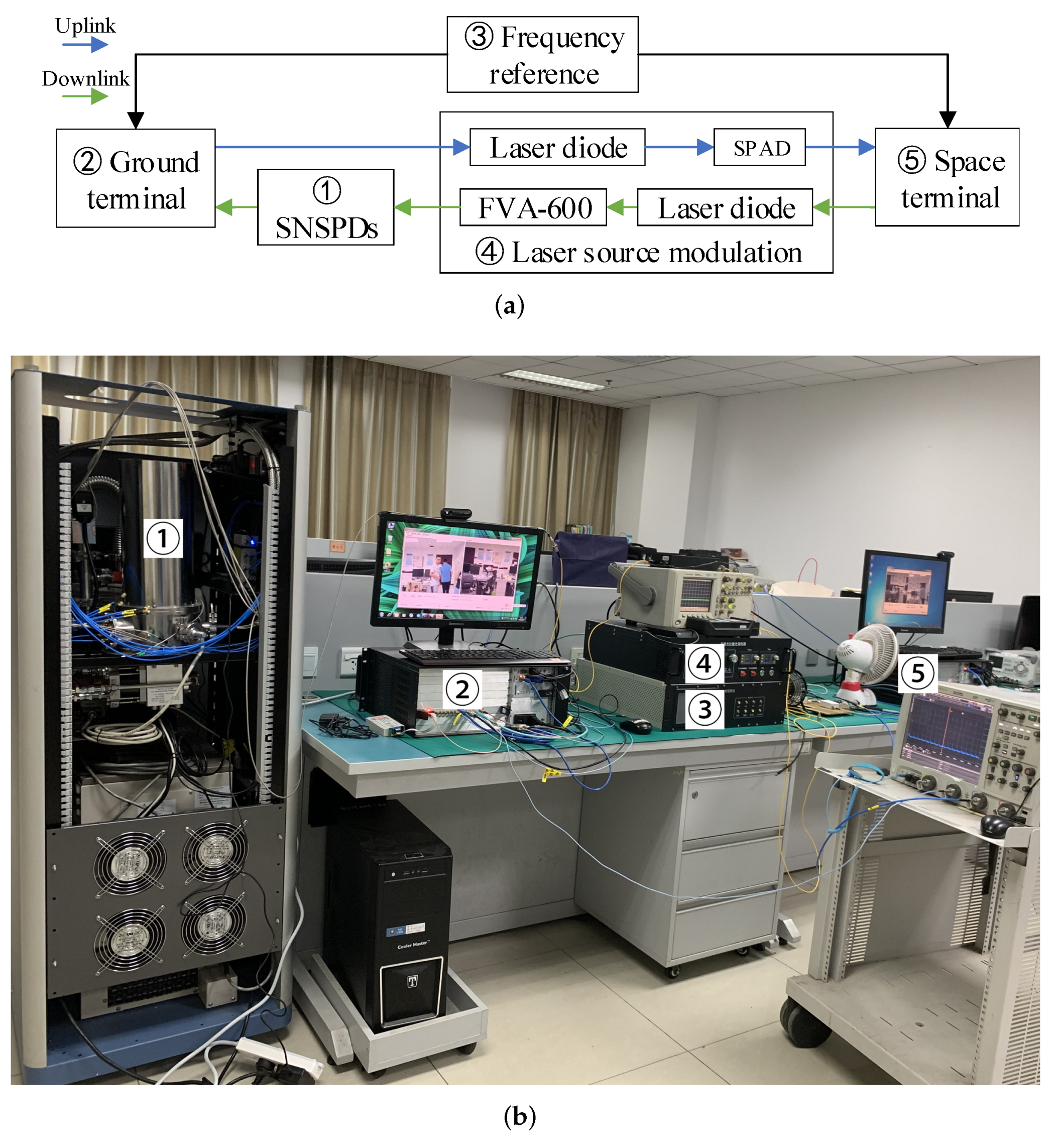
Figure 9.
Video transmission experiment results: (a) Experimental results at the ground terminal. (b) Experimental results at the space terminal. The local video is on the left and the received video is on the right in each subplot.
Figure 9.
Video transmission experiment results: (a) Experimental results at the ground terminal. (b) Experimental results at the space terminal. The local video is on the left and the received video is on the right in each subplot.
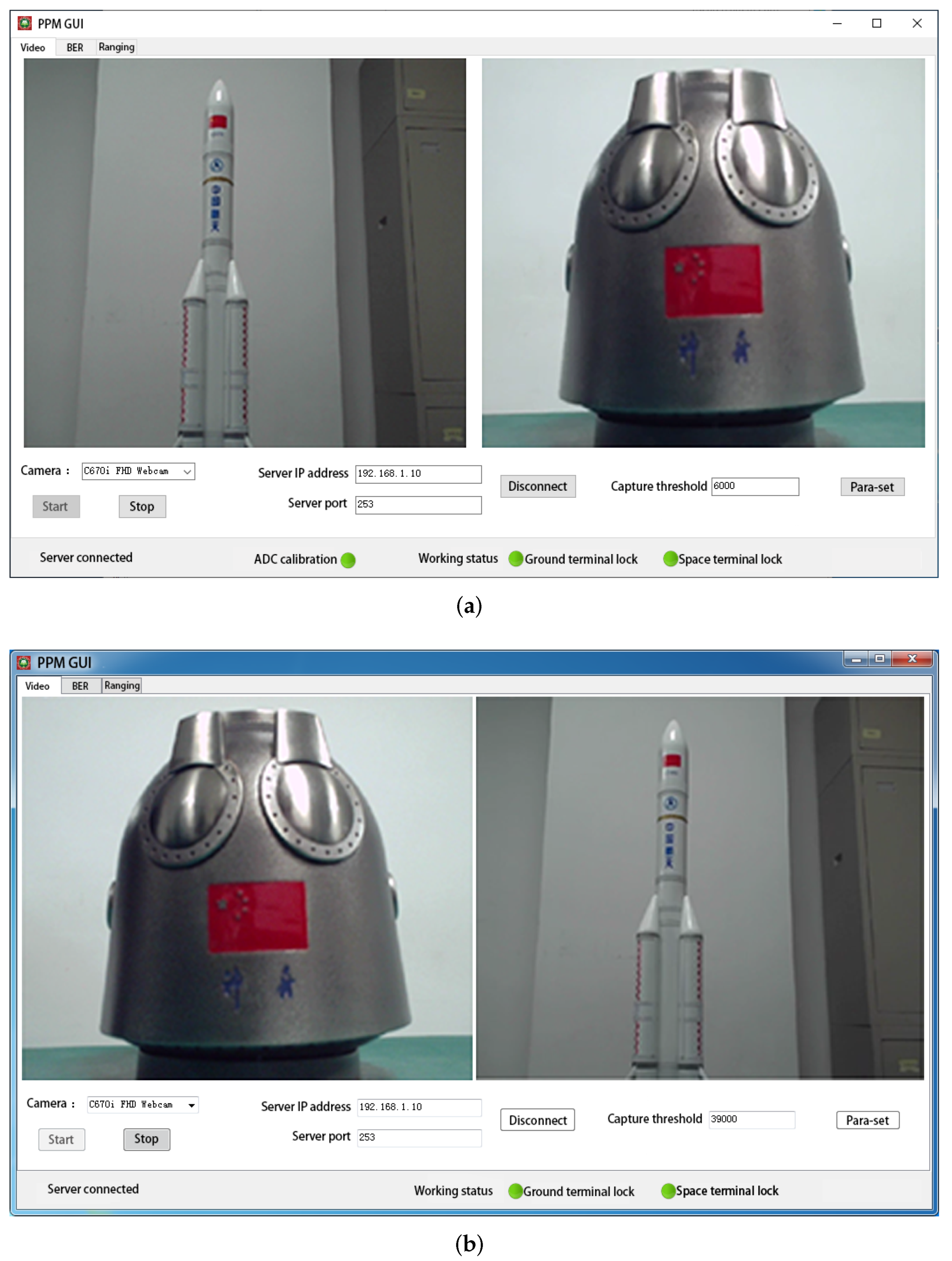
Figure 10.
Ranging results at different distances. (a) True distance is 50 cm. (b) True distance is 150 cm. (c) True distance is 300 cm. (d) True distance is 500 cm.
Figure 10.
Ranging results at different distances. (a) True distance is 50 cm. (b) True distance is 150 cm. (c) True distance is 300 cm. (d) True distance is 500 cm.

Table 1.
RMSE() results at different distances.
| True Distance/cm | 50 | 150 | 300 | 500 |
|---|---|---|---|---|
| Mean of ranging value/cm | 49.995 | 150.021 | 300.013 | 500.011 |
| RMSE/mm | 0.23 | 0.37 | 0.27 | 0.38 |
Publisher’s Note: MDPI stays neutral with regard to jurisdictional claims in published maps and institutional affiliations. |
© 2022 by the authors. Licensee MDPI, Basel, Switzerland. This article is an open access article distributed under the terms and conditions of the Creative Commons Attribution (CC BY) license (https://creativecommons.org/licenses/by/4.0/).
Share and Cite
MDPI and ACS Style
Hu, C.; Lin, Y.; Li, J.; Bu, X.; An, J. Near-Nyquist-Limit Optical Communication and Ranging Method Based on Waveform Matched PPM. Electronics 2022, 11, 565. https://doi.org/10.3390/electronics11040565
AMA Style
Hu C, Lin Y, Li J, Bu X, An J. Near-Nyquist-Limit Optical Communication and Ranging Method Based on Waveform Matched PPM. Electronics. 2022; 11(4):565. https://doi.org/10.3390/electronics11040565
Chicago/Turabian StyleHu, Chunyuan, Yujie Lin, Jianguo Li, Xiangyuan Bu, and Jianping An. 2022. "Near-Nyquist-Limit Optical Communication and Ranging Method Based on Waveform Matched PPM" Electronics 11, no. 4: 565. https://doi.org/10.3390/electronics11040565
Note that from the first issue of 2016, this journal uses article numbers instead of page numbers. See further details here.