
Finite-Time Parameter Observer-Based Sliding Mode Control for a DC/DC Boost Converter with Constant Power Loads


School of Automation, Nanjing University of Information Science and Technology, Nanjing 210044, China
*
Author to whom correspondence should be addressed.
Electronics 2022, 11(5), 819; https://doi.org/10.3390/electronics11050819
Submission received: 5 February 2022
/
Revised: 26 February 2022
/
Accepted: 1 March 2022
/
Published: 5 March 2022
(This article belongs to the Special Issue Power Electronics Converter Topologies and Control Techniques)
Abstract
:Constant power loads have negative impedance characteristics, which reduce the damping of DC/DC converter systems and have negative effects on the stability of the DC microgrid. In this paper, a finite-time parameter observer-based sliding mode controller is proposed for a boost converter with constant power loads. Firstly, a non-singular terminal sliding-mode controller is designed based on the flatness of the differential and sliding mode control theory. Secondly, a finite-time observer is designed to estimate the input voltage and tunes the parameter of the controller in time. Thirdly, the finite-time stability of the closed-loop system is proved through the proposed controller. Finally, the effectiveness and robustness of the proposed controller with unknown input voltage are verified by simulation. The proposed controller can guarantee finite-time convergence without input voltage sensors, which can reduce system cost and improve system reliability.
1. Introduction
Energy is the material basis for promoting economic and social development. Due to the exhaustion of traditional energy and increasing air pollution, the demand for renewable energy such as water, wind, and solar energy is gradually increasing [1]. Microgrids, which can flexibly integrate energy into power systems, mainly consist of loads, energy storage devices, distributed power sources, energy conversion devices, etc. [2]. At present, renewable energy is an important power source in the microgrid [3,4]. In order to improve resource utilization and power-supply reliability, the stable operation and power dispatch of renewable energy and microgrids have become a popular research topic. In [5], a robust, optimal power-management system is proposed for hybrid AC/DC microgrids to maximize the use of renewable energy and reduce the use of fuel energy. In [6], direct sliding mode controllers were designed combined with the perturb and observe method for DC boost converters to increase the photovoltaic system’s dynamic performance and ensure the stability of the system voltage.
In particular, the stable operation of DC microgrids has received a lot of attention from scholars [7,8]. Compared with AC microgrids, which have problems such as phase unbalance, harmonics, synchronization, and reactive power flow, DC microgrids are simpler to control [9,10]. In addition, DC microgrids can provide more efficient and more reliable integration of DC sources and DC loads than AC microgrids [11,12]. Nowadays, because of the increasing quantity of DC sources and the growing proportion of DC loads, DC microgrids are widely used.
DC/DC converters, which are usually used as the ports between renewable energy and the DC bus of the microgrid to ensure bus voltage stability, have become important parts of DC microgrids [13,14]. Due to the complexity of the actual working environment, DC microgrids are often affected by uncertainties such as power and load disturbances. If the DC/DC converters fail to handle these uncertainties immediately, this may cause instability in the DC microgrid. Many scholars have conducted research on the control problem of DC/DC converters to ensure the stability of DC microgrids. In [15], an SMC was designed for DC/DC boost converters. In [16], a total SMC was proposed for DC/DC converters to ensure tracking performance under the occurrence of system uncertainties. In [17], a novel non-linear model predictive control formulation was designed to realize the control of DC/DC converters in the microsecond range. In [18], a non-linear adaptive observer was designed for DC/DC converters to estimate load variations and state variables, which can improve the robustness of converter system control.
With the development of technology and the increasing use of power electronics devices, a large number of constant power loads (CPLs) have appeared in DC microgrids [19]. In order to increase the flexibility of voltage regulation, some DC/DC converters are used in the cascaded form [20,21]. However, when these converters are tightly controlled, the DC/DC converter loads behave as CPLs [22]. For CPLs, the input current is inversely proportional to the input voltage [23]. This phenomenon shows that CPLs have negative impedance characteristics, which can decrease system damping. Therefore, CPLs may reduce the performance of DC/DC converters and even cause the instability of DC microgrids [24,25]. Therefore, in order to ensure the stable operation of DC microgrids, the control problem of DC/DC converters with CPLs has attracted the attention of many scholars.
There are numerous strategies proposed for power electronics converter systems with CPLs to mitigate the impacts of CPLs. One of the basic control strategies is the passive-damping method, which adds necessary capacitors, resistors, and inductors to the system to increase system damping. However, this approach increases cost and decreases system efficiency. In order to reduce system loss, reference [26] proposed using loss-free resistors instead of resistors. However, the design of loss-free resistors is complex, so it is difficult to implement in the actual system. Another basic control strategy, which adds virtual impedance to the system by designing a control algorithm, is the active-damping method. Nevertheless, some active-damping methods are designed based on linear small-signal models, which are obtained by locally linearizing the system around the equilibrium point. If large disturbances occur in the system, their control performance is poor.
The DC/DC converter system with CPL is a non-linear system [27]. Linear controllers present difficulties in ensuring global stability. In order to solve the non-linearity of the DC/DC converter system feeding a CPL, many control algorithms have been designed, such as passive control [28,29] and backstepping control [30,31]. In [32], a method was proposed to transform a non-linear system into a linear system based on the flatness of the differential. In [33], an exact linearization and optimal tracking control method was designed for the boost converter with a CPL. In [34], a common controller-design methodology was proposed for the DC/DC converters with CPLs. In the above two control methods, the non-linear DC/DC converter systems were transformed into linear systems based on the feedback linearization and the flatness of the differentials. Compared with local linearization, feedback linearization, which is an efficient and reliable method to deal with the control problem of non-linear systems, not only simplifies the structure of the system but also retains the information about the higher derivatives of the system.
With the deepening of research on the DC/DC converter system feeding a CPL, the uncertainty and disturbance which exist in the actual operation of the converter were considered. At present, there are many control methods designed to address the control problems of the system caused by uncertainties and disturbances, such as adaptive control [35,36] and active disturbance-rejection control [37,38]. In [39], an objective holographic feedback linearization control method, which has strong robustness, was designed for the boost converter with CPL. In [40], a composite prescribed performance-control strategy based on feedback linearization was developed. A non-linear observer was designed to estimate the disturbance and adjust the output voltage. SMC is robust and can restrain external disturbances effectively [41,42]. Combining SMC with feedback linearization can deal with the non-linearity of the system and ensure the robustness of the system. In [43], an adaptive backstepping sliding mode control strategy for a boost converter with CPL was proposed, combined with feedback linearization technology. The robustness and stability analysis of the closed-loop system was clearly proved. In [44], based on feedback linearization, an SMC combined with a linear extended-state observer, which can ensure the stability of the closed-loop system with mismatched disturbance, was designed for DC/DC buck–boost converter systems. However, the above controllers can only guarantee the exponential convergence of the system.
The finite-time control can put the system under a faster convergence rate and has better disturbance-rejection ability [45]. In this paper, we designed a finite-time-parameter, observer-based sliding mode controller for DC/DC boost converters with constant power loads. The specific contributions of this paper are:
- A finite-time observer was designed to estimate the input voltage online and adjust the controller parameter. The observer just needs a very weak PE condition;
- A finite-time-parameter, observer-based sliding mode control for the boost converter feeding a CPL was designed to ensure the finite-time stability of the closed-loop system when the input voltage is unknown;
- The finite-time stability analysis of the proposed controller is also given.
2. Mathematical Model and Problem Formation
2.1. The State Space Model of a DC/DC Boost Converter Feeding a CPL
The state–space averaging technique was adopted to simplify the system analysis and the controller design [46]. The mathematical model of DC/DC boost converter with CPL, which operates in continuous-conduction mode (CCM), can be written as
where vc ∈ R > 0 is the capacitance voltage or the output voltage, iL ∈ R > 0 is the inductor current, C ∈ R > 0 is the capacitance value, L ∈ R > 0 is the inductance value, P ∈ R > 0 is the power of CPL, E ∈ R > 0 is the input voltage. u = 1 − d is the control input, where d ∈ [0, 1] is the duty ratio of the switch signal.
2.2. Problem Formation
The assumption of the DC/DC boost converter with CPL is given as follows.
Assumption 1.
The DC/DC boost converter feeding a CPL is working in CCM. The boost converter’s parameters C, L, and P are available constants. The input voltage E is an unknown constant.
The main aim of this paper is to design a control law combined with a parameter observer for System (1) to ensure the finite-time convergence of the closed-loop system. The proposed control law and the parameter observer have the following characteristics:
- The estimates of the parameter E can trace the real E in finite time. That is
- The output of the closed-loop system can converge to the desired value in finite time.
3. The Controller Design
A finite-time-parameter, observer-based sliding mode controller is designed in this section. Firstly, through coordinate transformation, System (1) is transformed into a linear state space model. Later on, based on non-singular terminal sliding-mode theory, a finite-time controller is designed. Finally, a finite-time parameter observer is designed to estimate the unknown E and adjust the controller parameters in time.
3.1. Coordinate Transformation
In this subsection, System (1) is transformed into a linear system model by input–output feedback linearization. Here, we assume that the input voltage is known. The case that the input voltage is unknown is discussed later. Based on the flatness of the differential, the sum of energy in inductance and capacitance is selected as a virtual output [32]. The expressions of the virtual output and its derivative to time are as follows
According to System (1), the time derivatives of the virtual output are obtained
It is obvious that the relative degree is equal to two for the virtual output y. Hence, inner dynamics are non-existent for this output.
The expected output voltage is . It is simple to determine that the expected equilibrium point is from the dynamic model (1). Then, the expected virtual output is obtained
The new states are defined that
Let
Then, the mapping from to , which is recorded as , is obtained
The Jacobian matrix of is computed as
While and are greater than zero, the matrix J is non-singular. Consequently, is a local diffeomorphism in the region where and are greater than zero. System (1) can be transformed into the following linear state space model.
3.2. The Design of the Non-singular Terminal Sliding-Mode Controller
According to sliding-mode control theory [47], a non-singular terminal sliding-mode controller is designed for System (11).
The sliding surface is designed as follows:
In addition, the following control law is designed
where p and q are positive odd integers and meet the condition , and k are controller parameters and meet the condition .
Proposition 1.
The state of System (11) is able to converge to zero in finite time under Sliding Surface (12) and Controller (13) for any initial state. That is
Proof of Proposition 1.
The Lyapunov function is selected as follows:
The expressions for the time derivative of function V1 are obtained
The time derivative of Sliding Surface (12) is derived as follows:
Substituting (13) and (17) into (16), one obtains
The time derivative of function V1 is negative semi-definite. When and , we can obtain from Equations (11) and (13). The state and the are not always equal to 0, when It can be concluded from [48] that the states of System (11) with all initial conditions can reach the designed sliding surface in finite time, which is recorded as .
For system states in the sliding surface, we can obtain
According to the model of System (11), one obtains
The time from to can be calculated that
Then, we can obtain
where . The proof of Proposition 2 is completed. □
According to Equations (4), (8), and (13), the finite-time control law for System (1) is obtained as follows:
3.3. The Design of the Parameter Observer
In this subsection, we consider the case that the input voltage E is unknown. According to reference [49], a finite-time-parameter observer is designed to estimate the input voltage E online.
Proposition 2.
Consider System (1), the finite-time input voltage observer, is as follows:
with the parametersis defined as
whereis a constant chosen by designer. We assume that ∃satisfies the following inequality:
then the observer outputcan trace the real E in finite time. That is,
Proof of Proposition 2.
According to System (1), we can obtain
where The error is defined by . Substituting (31) into (26), one obtains
The solution of the above function is
Substituting the solution of (27) into (33), it is obtained that
From Equation (29) and Inequality (30), we can obtain
Therefore, according to Equations (35) and (36), it can be obtained that
Under Function (28), we have
The proof of the observer-estimation finite-time convergence is completed. □
Through replacing the unknown E by the output of the parameter observer , a finite-time-parameter, observer-based sliding mode controller is obtained
Figure 2 shows the structure of the proposed controller.
3.4. Stability Analysis
Proposition 3.
Under Controller (38) with Observer (23)–(28), the output of System (1) can converge to the reference output voltage in finite time.
Proof of Proposition 3.
According to Proposition 3, when Consequently, we divide the proof process into two steps. Firstly, we prove that the states are bounded in the finite time . Secondly, we prove that the bounded states can converge to the expected states under Controller (38) with the condition in finite time.
Step 1: A function is defined that
The time derivative of is as follows:
Because the control input
and the duty ratio , we can obtain Then,
where . Since and are constants, the function is bounded, when . It can be concluded from [50] that are bounded and cannot escape into infinity in the finite time .
Step 2: when . We can obtain
and are considered as the initial time and the finite initial, respectively. We consider the stability of System (11) under Sliding Surface (42) and Control Law (43). According to Proposition 2, the state of System (11) is able to converge to zero in finite time. That is,
where . Because the mapping is a local diffeomorphism in the region where and are greater than zero, the output of System (1) can track the expected output under the control (44) in finite time. That is,
On the whole, under Controller (38) with the Observer (23)–(28), the output of System (1) can converge to the reference output voltage in finite time . The proof is completed. □
Remark 1.
The proposed controller can ensure the finite-time convergence of the closed-loop system in the case that the input voltage is unknown. Compared with the exponential convergence, the finite-time convergence can make the system have better transient performance and stronger robustness. Moreover, the controller-design step can be extended to the design of controllers for DC/DC boost converters with resistive loads, constant current loads, or mixed loads.
Remark 2.
We did not apply any treatments for chattering in this paper. Currently, many methods are available to restrain chattering. By using a disturbance observer, chattering can be weakened. The switching function gain k can be reduced to the upper bound of the observation error, which can realize the suppression of chattering [44,51].
4. Simulation Results
In this section, the proposed controller is used to control the boost converter feeding a CPL in a MATLAB/Simulink environment, and its effectiveness is verified. The simulation schematic of the proposed controller is shown in Figure 3. From the reference [33], the parameters adopted by boost converter are shown in Table 1. The initial output of the proposed observer is selected as 9 V to imitate the case that the input voltage E is unknown. The sliding surface parameters p and q are chosen as 5 and 3, respectively.
4.1. Scenario 1
Firstly, we test the performance of the proposed control method. The reference output voltage is set as The observer parameters are set as .
Figure 4 shows the transient of the closed-loop system. We can improve the convergence speed by increasing the values of and appropriately. However, a large value of k causes strong chattering and a large value of causes numerical errors in practice. When we select the values of k and , we should consider keeping the balance between the transient performance of the system and the amplitude of the chattering, and also need to consider the feasibility in practice. Figure 5 shows the transients of the controller with different parameters for the user to choose and reference according to the actual situation.
Moreover, we consider the step change in reference output voltage . At 0.02 s, is changed from 40 V to 50 V. When t = 0.04 s, is increased to 60 V.
The simulation result is revealed in Figure 6. The output voltage can track reference voltage precisely and quickly.
4.2. Scenario 2
Here, we test the tracking performance of the presented parameter observer with the controller’s parameters . When t = 0.05 s, there is a step change in input voltage E.
The output of the observer with different and are shown in Figure 7. We can increase the values of and appropriately to improve the tracking performance. The voltage estimates can converge to the real input voltage in finite time. After 0.05 s, the estimates still track the actual voltage in a short amount of time.
4.3. Scenario 3
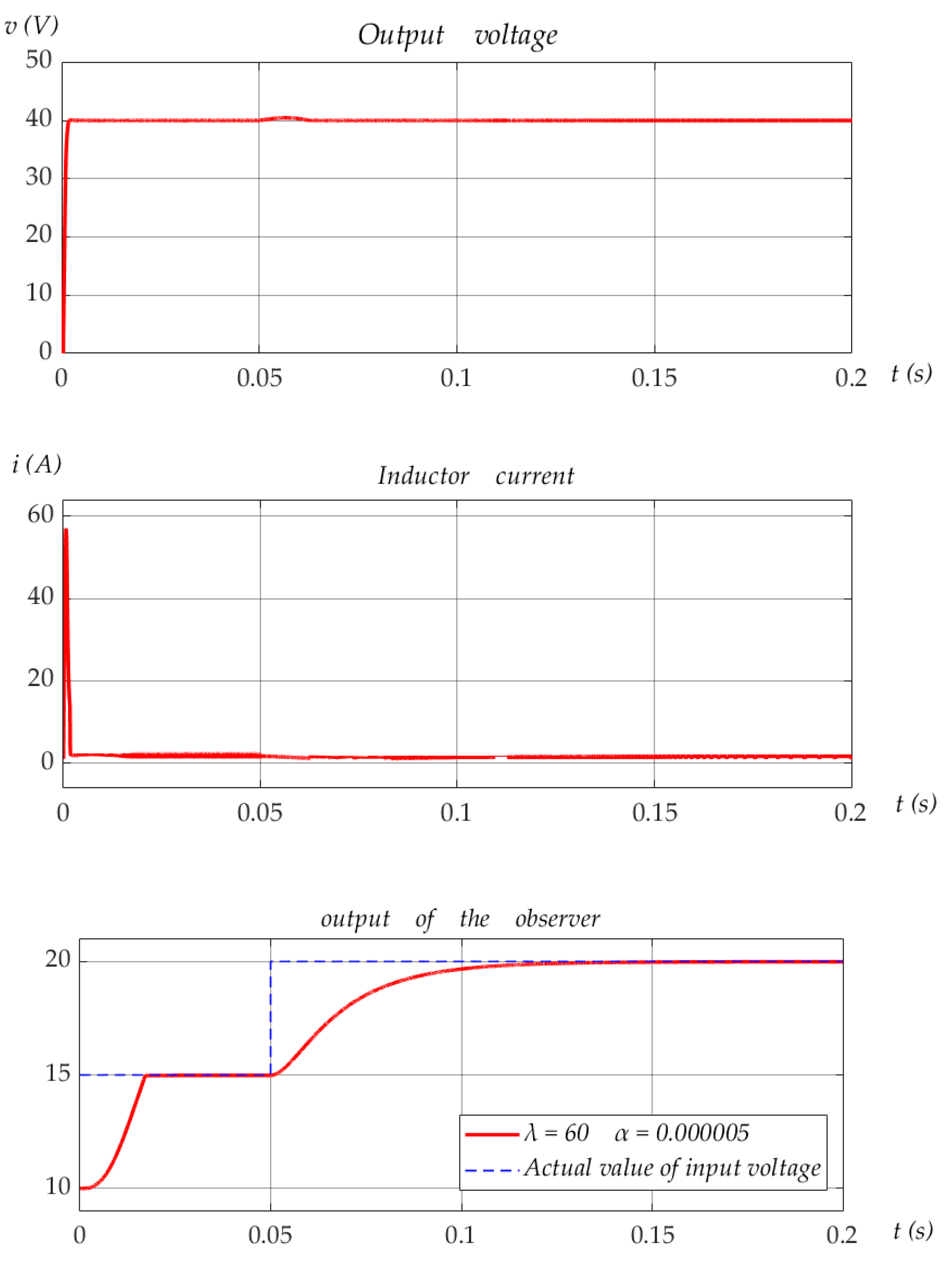
Finally, we verify the stability of the closed-loop system when there is a step change in the input voltage E. It changes from 15 V to 20 V at 0.04 s. The controller parameters are
Figure 8 demonstrates the simulation results. At 0.05 s, the output voltage converges to the reference voltage rapidly only after a small fluctuation. The proposed control method can effectively reduce the impact of input voltage disturbance on the system.
5. Conclusions
In this paper, we solved the finite-time control problem of a DC/DC boost converter feeding a CPL in the case that input voltage is unknown. Firstly, the non-linear state–space average model of the boost converter feeding a constant power load is transformed into a linear state–space model based on the flatness of the differential, which can address the non-linear and non-minimum phase problems of the system. Secondly, a non-singular terminal sliding-mode controller was designed for the linear system to ensure the finite-time stability and robustness of the system. Thirdly, in order to estimate the input voltage, a finite-time input voltage observer was designed. The output of the observer can trace the real input voltage E in finite time, which can improve the ability of the system to suppress disturbances caused by input-voltage fluctuations. By replacing the parameter E of the above non-singular terminal sliding-mode controller with the output of the observer, a finite-time-parameter, observer-based sliding mode controller was developed. Finally, simulation results verified the effectiveness of the designed control method. The proposed controller can ensure the finite-time stability of the closed-loop system without input voltage information. Compared with existing control techniques, which can ensure exponential stability, the controller proposed in this paper can provide faster convergence, higher tracking accuracy, and greater robustness, while the use of input-voltage sensors can be reduced to lower the cost of the system.
In future work, we plan to design an observer for the DC/DC converters with CPLs to realize the simultaneous estimation of inductance current and uncertain parameters. Based on the above ideas, an adaptive sensorless controller for converters is under study.
Author Contributions
Conceptualization, W.H.; Data curation, W.H.; Formal analysis, W.H.; Funding acquisition, W.H.; Methodology, W.H.; Project administration, W.H.; Resources, W.H.; Software, Y.S.; Supervision, W.H.; Validation, Y.S.; Writing—original draft, Y.S.; Writing—review & editing, W.H. All authors have read and agreed to the published version of the manuscript.
Funding
This research was supported in part by the National Natural Science Foundation (NNSF) of China (Grant No. 61903196), the Natural Science Foundation of Jiangsu Province of China (Grant No. BK20190773), the Natural Science Foundation of the Jiangsu Higher Education Institutions of China (Grant No. 19KJB510042), the Startup Foundation for Introducing Talent of NUIST (Grant No. 2018r084).
Conflicts of Interest
The authors declare no conflict of interest.
Nomenclature
| V | Capacitance voltage. | |
| A | Inductive current. | |
| E | V | Input voltage. |
| C | μF | Capacitance. |
| L | H | Inductance. |
| P | W | Power. |
| u | Control input. | |
| y | Virtual output. | |
| x | State vector. | |
| p | Sliding surface parameter. | |
| q | Sliding surface parameter. | |
| Sliding surface parameter. | ||
| Controller gain. | ||
| Filter gain. | ||
| Observer gain. | ||
| Observer parameter. | ||
| Estimation superscript. | ||
| Error superscript. | ||
| Reference footmark. | ||
| First-order time derivative superscript. | ||
| Second-order time derivative superscript. |
Abbreviations
| CPL | Constant power load. |
| SMC | Sliding mode control. |
| PE | Persistence of excitation. |
| CCM | Continuous-conduction mode. |
References
- Zhang, G.; Wu, Z.; Yu, S.S.; Trinh, H.; Zhang, Y. Four novel embedded Z-source DC–DC converters. IEEE Trans. Power Electron. 2022, 37, 607–616. [Google Scholar] [CrossRef]
- Zhu, X.; Zhang, B. High step-up quasi-Z-source DC-DC converters with single switched capacitor branch. J. Modern Power Syst. Clean Energy 2017, 5, 537–547. [Google Scholar] [CrossRef] [Green Version]
- Wu, M.; Lu, D.C. A novel stabilization method of lc input filter with constant power loads without load performance compromise in dc microgrids. IEEE Trans. Ind. Electron. 2015, 62, 4552–4562. [Google Scholar] [CrossRef]
- Yumei, L.I.; Zha, X.; Liu, F.; Sun, J. Stability control strategy for dc microgrid with constant power load. Electric Power Automat. Equip. 2014, 34, 57–64. [Google Scholar]
- Hosseinzadeh, M.; Salmasi, F.R. Robust optimal power management system for a hybrid ac/dc micro-grid. IEEE Trans. Sustain. Energy 2015, 6, 675–687. [Google Scholar] [CrossRef]
- Al-Wesabi, I.; Fang, Z.; Wei, Z.; Dong, H. Direct sliding mode control for dynamic instabilities in DC-link voltage of standalone photovoltaic systems with a small capacitor. Electronics 2022, 11, 133. [Google Scholar] [CrossRef]
- Mosayebi, M.; Sadeghzadeh, S.M.; Gheisarnejad, M.; Khooban, M.H. Intelligent and fast model-free sliding mode control for shipboard dc microgrids. IEEE Trans. Transp. Electrif. 2020, 7, 1662–1671. [Google Scholar] [CrossRef]
- Babaiahgari, B.; Jeong, Y.; Park, J.D. Stability enhancement method for DC microgrids with constant power loads using variable inductor. In Proceedings of the 2020 IEEE Applied Power Electronics Conference and Exposition (APEC), New Orleans, LA, USA, 15–19 March 2020. [Google Scholar]
- Xiao, J.; Wang, P.; Setyawan, L. Hierarchical control of hybrid energy storage system in dc microgrids. IEEE Trans. Ind. Electron. 2015, 62, 4915–4924. [Google Scholar] [CrossRef]
- Bagheri, S.; CheshmehBeigi, H.M. DC microgrid voltage stability through inertia enhancement using a bidirectional DC-DC converter. In Proceedings of the 7th Iran Wind Energy Conference, Shahrood, Iran, 17–18 May 2021. [Google Scholar]
- Jin, C.; Wang, P.; Xiao, J.; Tang, Y.; Choo, F.H. Implementation of hierarchical control in dc microgrids. IEEE Trans. Ind. Electron. 2014, 61, 4032–4042. [Google Scholar] [CrossRef]
- Chandra, A.; Singh, G.K.; Pant, V. Protection techniques for dc microgrid—A review. Electric Power Syst. Res. 2020, 187, 106439. [Google Scholar] [CrossRef]
- Alrajhi, H. A generalized state space average model for parallel DC-to-DC converters. Comput. Syst. Sci. Eng. 2022, 41, 717–734. [Google Scholar] [CrossRef]
- Chincholkar, S.H.; Chan, C.Y. Comparative study of current-mode controllers for the positive output elementary Luo converter via state-space and frequency response approaches. IET Power Electron. 2015, 8, 1137–1145. [Google Scholar] [CrossRef]
- Hanifi, G. Sliding mode control of dc-dc boost converter. J. Appl. Sci. 2005, 5, 588–592. [Google Scholar]
- Wai, R.J.; Shih, L.C. Design of voltage tracking control for dc–dc boost converter via total sliding-mode technique. IEEE Trans. Ind. Electron. 2011, 58, 2502–2511. [Google Scholar] [CrossRef]
- Microsecond nonlinear model predictive control for DC-DC converters. Int. J. Circuit Theory Appl. 2020, 48, 406–419. [CrossRef]
- Belhaj, F.Z.; Fadil, H.E.; Idrissi, Z.E.; Gaouzi, K.; Rachid, A. Adaptive observer design for non-linear cascade boost converter. In Proceedings of the 2020 International Conference on Electrical and Information Technologies (ICEIT), Rabat, Morocco, 4–7 March 2020. [Google Scholar]
- Eklas, H.; Ron, P.; Adel, N.; Sanjeevikumar, P. A comprehensive review on constant power loads compensation techniques. IEEE Access 2018, 6, 33285–33305. [Google Scholar]
- Meng, L.; Shafiee, Q.; Trecate, G.F.; Karimi, H.; Fulwani, D.; Lu, X.; Guerrero, J.M. Review on control of DC microgrids and multiple microgrid clusters. IEEE J. Emerg. Sel. Topics Power Electron. 2017, 5, 928–948. [Google Scholar]
- Xu, Q.; Wang, P.; Chen, J.; Wen, C.; Lee, M.Y. A module-based approach for stability analysis of complex more-electric aircraft power system. IEEE Trans. Transp. Electrif. 2017, 3, 901–919. [Google Scholar] [CrossRef]
- Singh, S.; Gautam, A.R.; Fulwani, D. Constant power loads and their effects in DC distributed power systems: A review. Renew. Sustain. Energy Rev. 2017, 72, 407–421. [Google Scholar] [CrossRef]
- Wei, L.; Huang, M.; Sun, J.; Zha, X. Nonlinear analysis of photovoltaic battery hybrid power system with constant power loads. Trans. China Electrotech. Soci. 2017, 32, 128–137. [Google Scholar]
- Riccobono, A.; Santi, E. Comprehensive review of stability criteria for dc power distribution systems. IEEE Trans. Ind. Appl. 2014, 50, 3525–3535. [Google Scholar] [CrossRef]
- Zhang, X.; Ruan, X. Adaptive active capacitor converter for improving the stability of cascaded DC power supply system. Trans. China Electrotech. Soc. 2012, 27, 23–32. [Google Scholar] [CrossRef]
- Singer, S.; Ozeri, S.; Shmilovitz, D. A pure realization of loss-free resistor. IEEE Trans. Circuits Syst. I Regul. Papers 2004, 51, 1639–1647. [Google Scholar] [CrossRef]
- Xu, Q.; Yan, Y.; Zhang, C.; Dragicevic, T.; Blaabjerg, F. An offset-free composite model predictive control strategy for dc/dc buck converter feeding constant power loads. IEEE Trans. Power Electron. 2019, 35, 5331–5342. [Google Scholar] [CrossRef]
- Kwasinski, A.; Krein, P.T. Passivity-based control of Buck converters with constant-power loads. In Proceedings of the IEEE Power Electronics Specialists Conference, Orlando, FL, USA, 17–21 June 2007. [Google Scholar]
- Kwasinski, A.; Krein, P.T. Stability of constant power loads in DC-DC converters using passivity-based control. In Proceedings of the International IEEE Telecommunications Energy Conference, Rome, Italy, 30 September–4 October 2007. [Google Scholar]
- Xu, Q.; Jiang, W.; Blaabjerg, F.; Zhang, C.; Fernando, T. Backstepping control for large signal stability of high boost ratio interleaved converter interfaced DC microgrids with constant power loads. IEEE Trans. Power Electron. 2020, 35, 5397–5407. [Google Scholar] [CrossRef]
- Yousefizadeh, S.; Bendtsen, J.D.; Vafamand, N.; Khooban, M.H.; Blaabjerg, F.; Dragicevic, T. Tracking control for a DC microgrid feeding uncertain loads in more electric aircraft: Adaptive backstepping approach. IEEE Trans. Ind. Electron. 2019, 66, 5644–5652. [Google Scholar] [CrossRef] [Green Version]
- Fliess, M.; LéVINE, J.; Martin, P.; Rouchon, P. Flatness and defect of non-linear systems: Introductory theory and examples. Int. J. Control 2003, 61, 1327–1361. [Google Scholar] [CrossRef] [Green Version]
- Gao, Z.; Lin, H.; Zhang, X. Exact linearization and optimal tracking control of boost converter with constant power loads. Proc. Chin. Soc. Electrical Eng. 2007, 13, 70–75. [Google Scholar]
- Tomassini, J.; Junco, S.; Donaire, A. Dealing with constant power loads in DC-DC power electronic converters using flatness based coordinate transformations. In Proceedings of the 2020 IEEE Congreso Bienal de Argentina, Resistencia, Argentina, 1–4 December 2020. [Google Scholar]
- Hassan, M.A.; Li, E.P.; Li, X.; Li, T.; Duan, C.; Chi, S. Adaptive passivity-based control of dc–dc buck power converter with constant power load in DC microgrid systems. IEEE J. Emerg. Sel. Topics Power Electron. 2019, 7, 2029–2040. [Google Scholar] [CrossRef]
- He, W.; Ortega, R. Design and implementation of adaptive energy shaping control for dc-dc converters with constant power loads. IEEE Trans. Ind. Inf. 2019, 16, 5053–5064. [Google Scholar] [CrossRef]
- Yang, J.X.; Wang, J.H.; Sun, S.T.; Wang, Z.Y. Nonlinear control of boost converter with constant power load. J. Liaoning Tech. Univ. 2020, 39, 338–343. [Google Scholar]
- Gheisarnejad, M.; Khooban, M.H. IoT-Based DC/DC deep learning power converter control: Real-time implementation. IEEE Trans. Power Electron. 2020, 35, 13621–13630. [Google Scholar] [CrossRef]
- Li, J.; Pan, H.; Long, X.; Liu, B. Objective holographic feedbacks linearization control for boost converter with constant power load. Int. J. Electrical Power Energy Syst. 2022, 134, 107310. [Google Scholar] [CrossRef]
- Xu, X.; Liu, Q.; Zhang, C.; Zeng, Z. Prescribed performance controller design for DC converter system with constant power loads in DC microgrid. IEEE Trans. Syst. 2020, 50, 4339–4348. [Google Scholar] [CrossRef]
- Zheng, C.; Dragicevic, T.; Zhang, J.; Chen, R.; Blaabjerg, F. Composite robust quasi-sliding mode control of dc-dc buck converter with constant power loads. IEEE J. Emerg. Selected Topics Power Electron. 2020, 9, 1455–1464. [Google Scholar] [CrossRef]
- Shtessel, Y.; Edwards, C.; Fridman, L.; Levant, A. Sliding Mode Control and Observation; Springer: New York, NY, USA, 2014. [Google Scholar]
- Wu, J.; Lu, Y. Adaptive backstepping sliding mode control for boost converter with constant power load. IEEE Access 2019, 7, 50797–50807. [Google Scholar] [CrossRef]
- Linares-Flores, J.; Juarez-Abad, J.A.J.; Hernandez-Mendez, A.; Castro-Heredia, O.; Castro-Heredia, J.F.; Heredia-Barba, R.R.; Curiel-Olivares, G. Sliding mode control based on linear extended state observer for DC-to-DC buck-boost power converter system with mismatched disturbances. IEEE Trans. Ind. Appl. 2022, 58, 940–950. [Google Scholar] [CrossRef]
- Yuan, C.; Huangfu, Y.; Ma, R. Adaptive finite-time control of DC-DC converter feeding constant power load for fuel cell vehicle. In Proceedings of the 2020 IEEE Industry Applications Society Annual Meeting, Detroit, MI, USA, 10–16 October 2020. [Google Scholar]
- Erickson, R.W.; Maksimović, D. Fundamentals of Power Electronics, 3rd ed.; Springer: Cham, Switzerland, 2006. [Google Scholar]
- Feng, Y.; Bao, S.; Xing, Y.U. Design method of non-singular terminal sliding mode control systems. Control Decis. 2002, 17, 194–198. [Google Scholar]
- Gui, J.; Zhang, L.; Li, S.; Wang, X. Nonsingular terminal sliding mode control for PMSM servo system based on backlash compensation and high-order sliding mode observer. In Proceedings of the 2020 Chinese Control and Decision Conference (CCDC), Hefei, China, 22–24 August 2020. [Google Scholar]
- Bobtsov, A.; Ortega, R.; Yi, B.; Nikolaev, N. Adaptive state estimation of state-affine systems with unknown time-varying parameters. Int. J. Control 2021. [Google Scholar] [CrossRef]
- Lu, Z.; Zuo, W.; Li, S.; Ding, B.; Du, H. Universal finite-time observer based second-order sliding mode control for dc-dc buck converters with only output voltage measurement. J. Frankl. Inst. 2020, 357, 11863–11879. [Google Scholar]
- Zhao, X.; Ma, X.; Ma, X. A novel disturbance observer for multiagent tracking control with matched and unmatched uncertainties. Math. Probl. Eng. 2019. [Google Scholar] [CrossRef] [Green Version]
Figure 1.
The circuit topology of DC/DC boost converter with CPL.
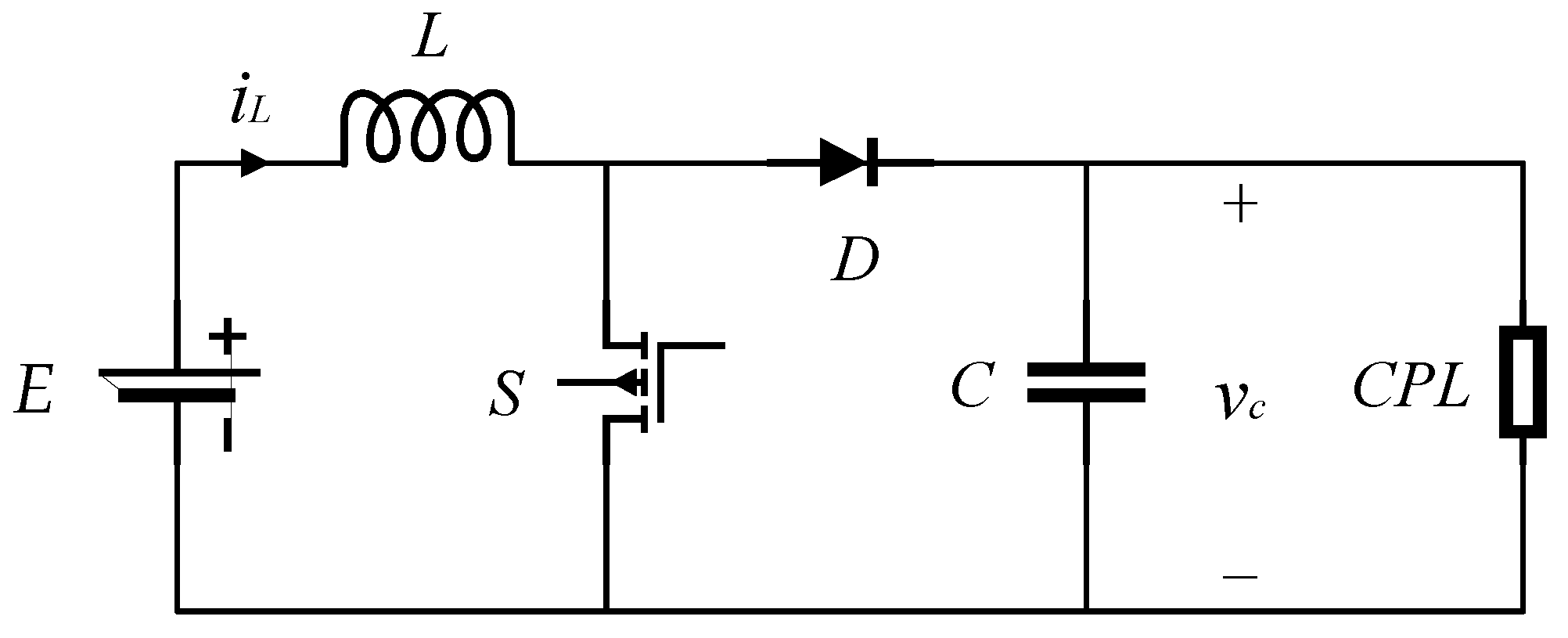
Figure 2.
The structure of the proposed controller.
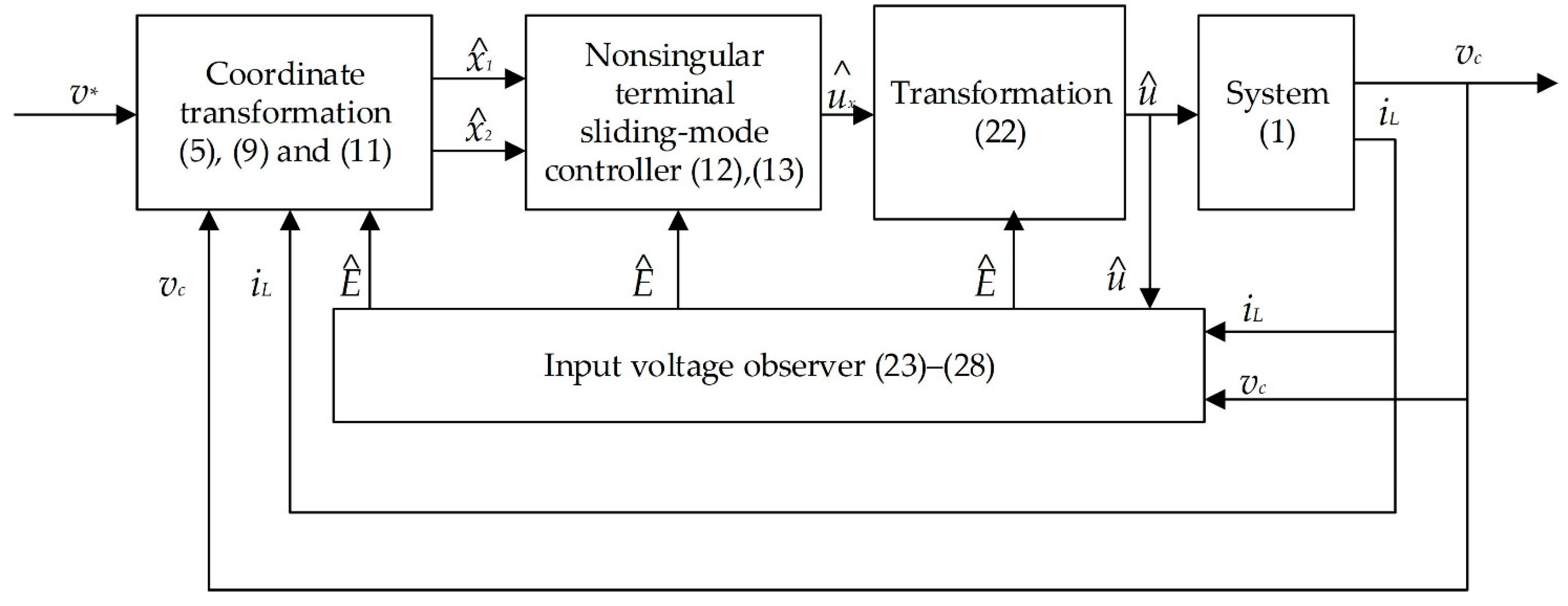
Figure 3.
The simulation schematic of the proposed controller.
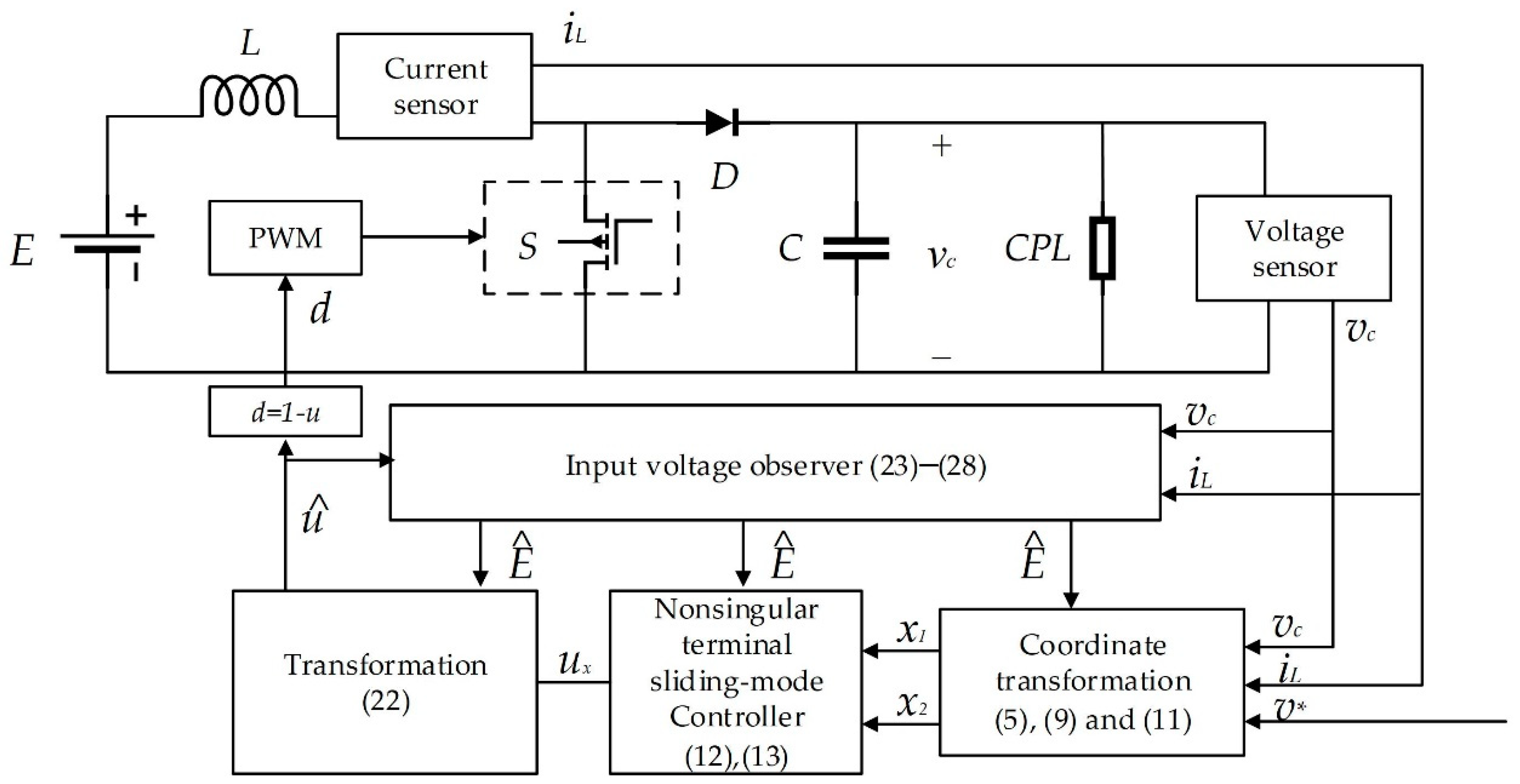
Figure 4.
Transient of boost converter feeding CPL under the proposed controller.
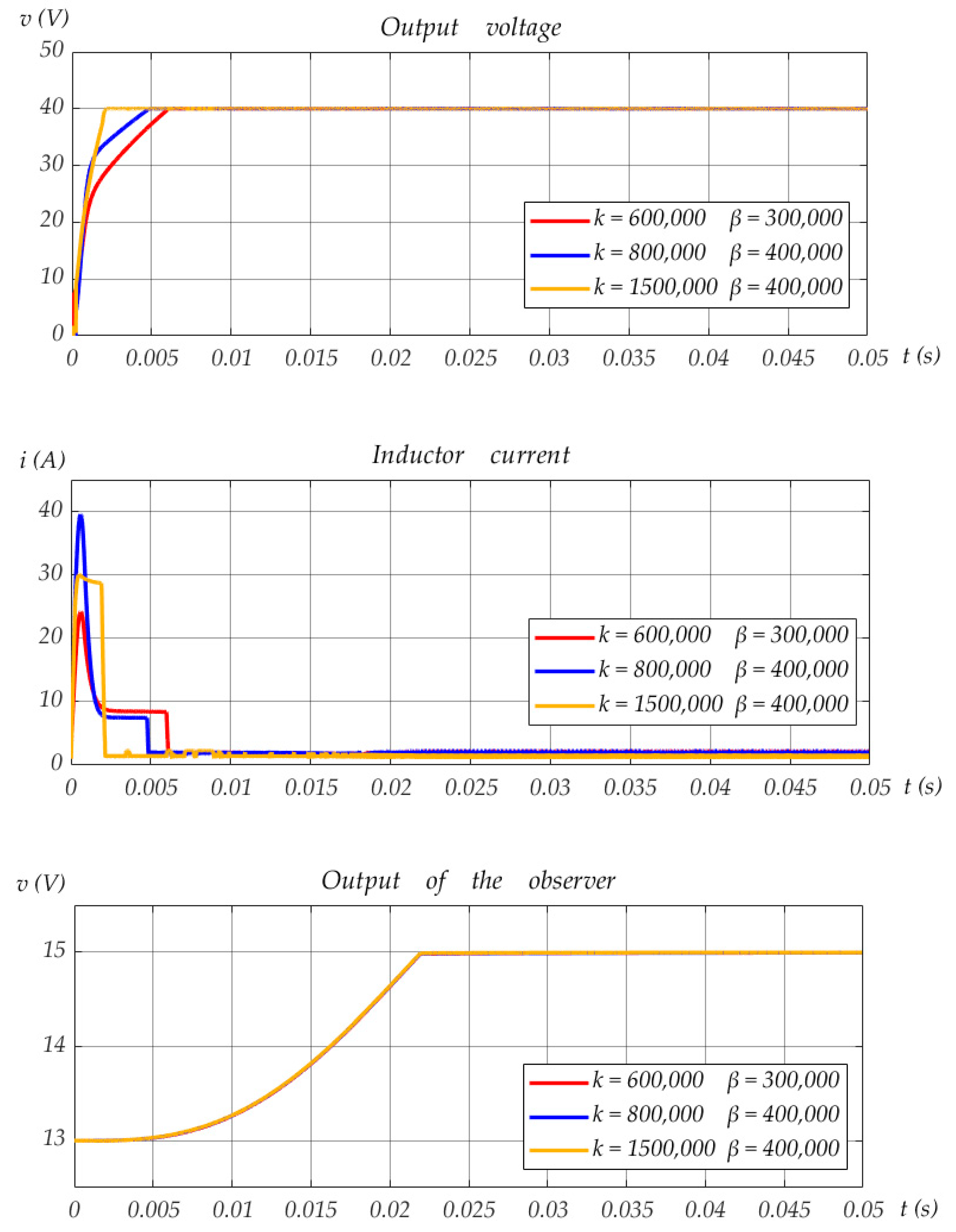
Figure 5.
Transient of boost converter feeding CPL under the proposed controller with different parameters.
Figure 5.
Transient of boost converter feeding CPL under the proposed controller with different parameters.
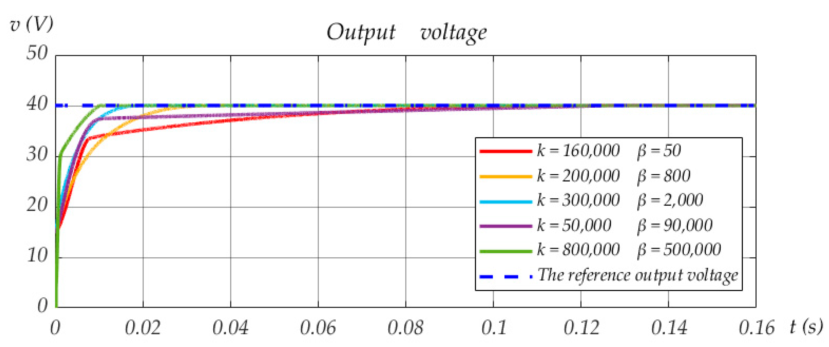
Figure 6.
Simulation results with step change in reference output voltage.
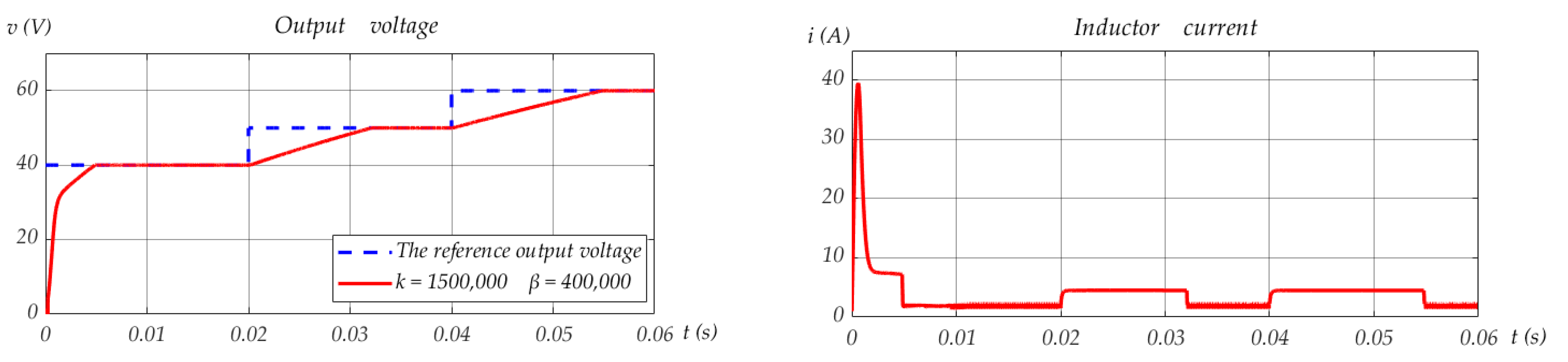
Figure 7.
Response curves of the proposed observer with different and .
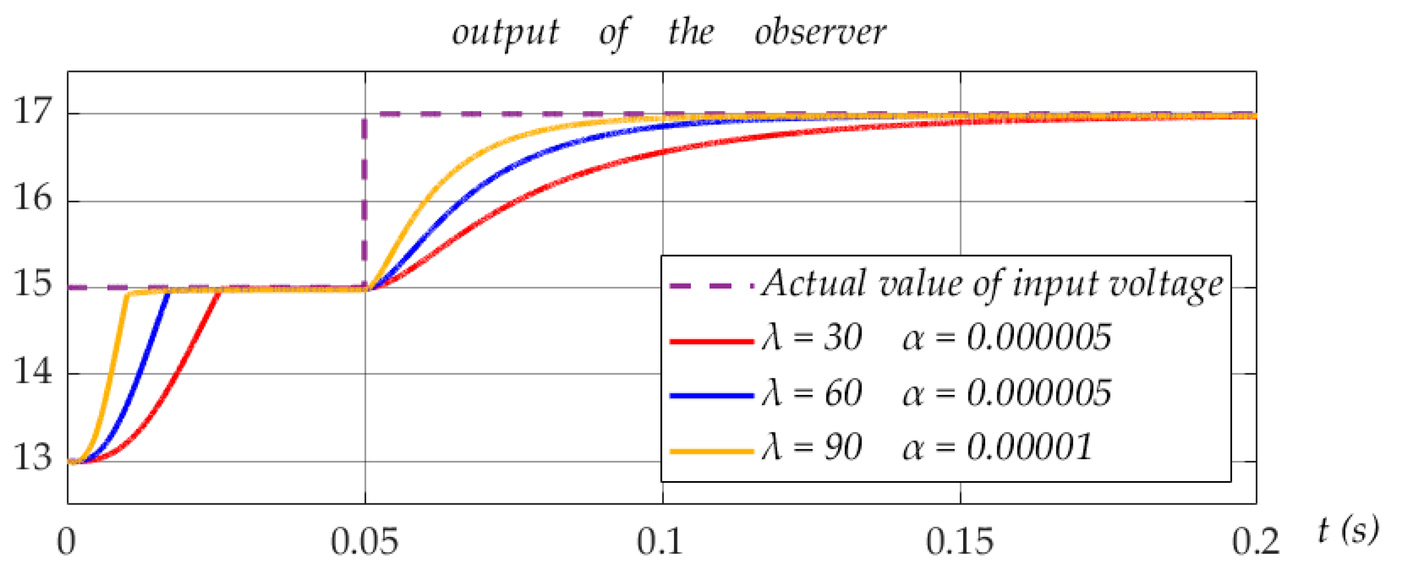
Figure 8.
Response curves of boost converter feeding CPL under the proposed controller with the step change in E.
Figure 8.
Response curves of boost converter feeding CPL under the proposed controller with the step change in E.

Table 1.
The parameters of boost converter with CPL.
| Parameters | Symbols | Values |
|---|---|---|
| Input Voltage | E | 15 V |
| Power of the CPL | P | 30 W |
| Inductance | L | 147 μH |
| Capacitance | C | 1000 μF |
Publisher’s Note: MDPI stays neutral with regard to jurisdictional claims in published maps and institutional affiliations. |
© 2022 by the authors. Licensee MDPI, Basel, Switzerland. This article is an open access article distributed under the terms and conditions of the Creative Commons Attribution (CC BY) license (https://creativecommons.org/licenses/by/4.0/).
Share and Cite
MDPI and ACS Style
He, W.; Shang, Y. Finite-Time Parameter Observer-Based Sliding Mode Control for a DC/DC Boost Converter with Constant Power Loads. Electronics 2022, 11, 819. https://doi.org/10.3390/electronics11050819
AMA Style
He W, Shang Y. Finite-Time Parameter Observer-Based Sliding Mode Control for a DC/DC Boost Converter with Constant Power Loads. Electronics. 2022; 11(5):819. https://doi.org/10.3390/electronics11050819
Chicago/Turabian StyleHe, Wei, and Yukai Shang. 2022. "Finite-Time Parameter Observer-Based Sliding Mode Control for a DC/DC Boost Converter with Constant Power Loads" Electronics 11, no. 5: 819. https://doi.org/10.3390/electronics11050819
Note that from the first issue of 2016, this journal uses article numbers instead of page numbers. See further details here.