
A Windmill-Shaped SSPP Waveguide for High-Efficiency Microwave and Terahertz Propagation


1
Southwest China Institute of Electronic Technology, Chengdu 610036, China
2
Institute of Electromagnetics and Acoustics, Xiamen University, Xiamen 361005, China
3
State Key Laboratory of Complex Electromagnetic Environment Effects on Electronics and Information System, Luoyang 471003, China
4
State Key Laboratory of Millimeter Waves, Southeast University, Nanjing 210096, China
5
Shenzhen Research Institute, Xiamen University, Shenzhen 518057, China
*
Author to whom correspondence should be addressed.
Electronics 2022, 11(9), 1293; https://doi.org/10.3390/electronics11091293
Submission received: 2 March 2022
/
Revised: 30 March 2022
/
Accepted: 14 April 2022
/
Published: 19 April 2022
(This article belongs to the Special Issue Physics and Applications of Terahertz Metasurfaces)
Abstract
:We propose a novel type of spoof surface plasmon polariton (SSPP) waveguide based on windmill-shaped units for high-efficiency microwave and terahertz propagation. The dependence of terahertz dispersion characteristics on geometrical parameters of the proposed waveguide is detailed and investigated. Compared with the conventional comb-shaped and T-shaped SSPP waveguide units, the proposed windmill-shaped unit shows a lower asymptotic frequency and stronger field-confinement characteristics for the supported fundamental SSPP mode. To demonstrate the properties of the windmill-shaped SSPP waveguide, a tapered conversion is designed to connect the windmill-shaped SSPP waveguide and the microstrip for smooth momentum and impedance matching. The simulated results show that the whole waveguide has excellent transmission performance with S11 < −10 dB and S21 > −1 dB from 0 THz to 5.68 THz, as well as a large out-of-band rejection response (S21 < −80 dB). Then, a scaled microwave windmill-shaped waveguide prototype is fabricated and measured. The numerical and experimental results are in good agreement, which further validates the proposed SSPP waveguide design. The proposed waveguide has excellent microwave and terahertz propagation and rejection characteristics, which may have great potential applications in various microwave and terahertz devices and circuits.
1. Introduction
The surface plasmon polaritons (SPPs) are a near-field electromagnetic wave propagating along with the metal-dielectric interface, which is produced by the interaction of light waves with electrons on the interface between metal and a dielectric [1]. Because of the coupling effect of free electrons and photons on the metal surface, SPPs can break the diffraction limit and achieve sub-wavelength confinement. When the SPPs propagate along with a metal–dielectric interface, the energy of the electromagnetic wave decreases exponentially in the perpendicular direction. These unique electromagnetic characteristics make them widely used in various fields such as biosensors [2], nano-imaging [3], miniaturized photonic circuits [4], and near-field detection [5]. Due to the high plasma frequencies of metals, natural SPPs usually exist in the visible and ultraviolet regimes. In microwave and terahertz frequencies, metals act as ideal conductors and therefore cannot support the natural SPPs [6]. To mimic the electromagnetic properties of SPPs at optical frequencies, the concept of spoof SPPs (SSPPs) or designer SPPs, supported by various corrugated bulk metal surface with hole arrays, grooved metal wires, and domino waveguides, was proposed for microwave and terahertz applications [7,8,9,10,11]. The dispersion characteristics of SSPPs are not only similar to SPPs, but also can be adjusted by changing the geometrical parameters of metal surface structures [12,13]. Since the SSPPs are a variety of slow waves, such as the SPPs in optical regime, the phase velocity of the SSPPs propagation along the waveguide is smaller than the light speed in a vacuum. In recent years, to further reduce the size of SSPP waveguide for better integration applications, many ultra-thin corrugated strip structures with single-corrugated, double-corrugated, staggered, V-shaped, and folded unit arrays have been demonstrated [14,15,16,17]. Based on these structures, a large number of planar SSPP circuits and devices, including filters, dividers, couplers, antennas sensors, have been proposed and investigated in the microwave and terahertz region [18,19,20,21,22,23,24,25,26]. The ultra-thin-strip-based SSPP waveguides and devices can be easily produced by the standard printed circuit board (PCB) processes. It is very important to develop new compact, ultra-thin SSPP waveguides with low loss and high performance for highly integrated plasmonic circuit and system applications.
In this paper, we propose a new type of ultra-thin windmill-shaped SSPP waveguides based on the concept of SSPPs. First, the dispersion relations of the proposed waveguide are investigated. It is found that the asymptotic frequency is less than the asymptotic frequency of the conventional comb-shaped and T-shaped SSPP waveguides, which implies great potential in highly integrated plasmonic device applications. Second, a conversion is designed to connect the windmill waveguide with microstrips, and to achieve momentum matching and impedance matching. The simulation results show that the proposed waveguide behaves as an ultra-wideband terahertz lowpass filter, which has good in passband transmission performance and good out-of-band suppression. To verify the proposed design, a proportionally enlarged windmill-shaped waveguide prototype is fabricated and measured in the microwave region. The transmission characteristics of the waveguide under different bend angles are also measured and analyzed.
2. Dispersion Characteristics of the Windmill-Shaped SSPP Unit
The configuration of the unit cell of the terahertz windmill-shaped SSPP waveguide is shown in Figure 1a, which consists of the “fan blade” above and the “bracket” below, wherein the “bracket” is a conventional comb SSPP waveguide. The geometric parameters of the windmill-shaped SSPP unit are set as: p = 6 μm, w = 1 μm, a = 1 μm, h = 3 μm, m = 2.5 μm, n = 0.5 μm, m1 = 1 μm, and n1 = 1 μm. Metal and dielectric substrates are made of copper with conductivity of 5.8 × 10⁷ S/m and Rogers 5880 substrate with relative permittivity of 2.2 and a loss tangent of 0.0009. The thickness of the metal layer is t1 = 0.018 μm, and the thickness of the dielectric substrate is t2 = 0.508 μm.
To better understand the mechanism of the proposed SSPP waveguide, we compare the dispersion curves of the windmill-shaped, comb-, and T-shaped waveguide units, as shown in Figure 1b. Here, we only consider the SSPP propagation along the waveguides in the x-direction. When simulating the dispersion curves, we define all the different SSPP units as having the same period of p along the x-direction, and calculate the eigenfrequencies of SSPP unit under different phase shifts between the periodic boundaries in the x direction. Meanwhile, the boundary conditions for y and z directions are all set as PEC, far enough away from the SSPP unit structure. The detailed dimension parameters for different SSPP units are shown in Figure 1. It is found that the asymptotic frequency of the proposed waveguide dispersion curve is 5.73 THz, which is lower than that of the comb and T-shaped waveguide. Since the decay constant α of the SSPPs can be obtained by
where kx and k0 are wave vectors in the SSPP waveguide and in free space, respectively, the larger kx will result in a larger value of α, implying the field confinement will be stronger. The lower the asymptotic frequency, the stronger the field confinement of the SSPPs waveguide will be. Therefore, the windmill-shaped SSPP waveguide has an obvious advantage of higher field confinement.
Furthermore, it is worth noting that of the scale invariance of the electromagnetic dispersion characteristics, the proposed terahertz windmill-shaped SSPP waveguide can be scaled down to the microwave frequencies with the exactly the same properties. By proportionally scaling up all the dimensions of the windmill-shaped SSPP unit by 1000 times from μm to mm (p = 6 mm, w = 1 mm, a = 1 mm, h = 3 mm, m = 2.5 mm, n = 0.5 mm, m1 = 1 mm, n1 = 1 mm, t1 = 0.018 mm, and t2 = 0.508 mm), the operating frequency of the waveguide will switch from THz to GHz. As clearly shown in Figure 1c, the dispersion relation shows the same shape as that shown in Figure 1b, implying great potential applications for microwave and terahertz SSPP circuits and devices.
Figure 2a,b show the dependence of the dispersion relation on two geometric parameters m and n1 of the terahertz windmill-shaped waveguide at terahertz frequencies. The unit cell asymptotic frequency significantly decreases from 6.37, 5.73, 5.20, to 4.96 GHz as m increases from 2, 2.5, 3, to 3.25 μm when n1 is fixed as 1 μm, as well as from 6.40, 6.04, 5.73, to 5.37 GHz as n1 increases from 0, 0.5, 1, to 1.5 μm when m is fixed as 2.5 μm. Therefore, the dispersion characteristics of the windmill-shaped waveguide can be flexibly engineered by changing the values of these two parameters. Similarly, by proportionally scaling up all the dimensions of the windmill-shaped SSPP unit by 1000 times from μm to mm, the dependence of the dispersion relations on the geometric parameters of the microwave windmill-shaped SSPP unit shows the same characteristics as those in the terahertz range, as clearly shown in Figure 2c,d.
3. Results and Discussion
To investigate the properties of the windmill-shaped SSPP waveguide, a windmill waveguide with two quasi-TEM to SSPP mode conventions is designed, as shown in Figure 3. In this design, the length and width of the two micriostrips are set as l1 = 5 μm and w1 = 1.49 μm. The dimension parameters of the 18 uniform windmill-shaped SSPP unit are consistent with those of Figure 1. Each mode conversion is composed of an array of 14 tapered windmill-shaped SSPP units with the size increasing gradually in proportions of 0.23, 0.25, 0.28, 0.31, 0.35, 0.39, 0.43, 0.48, 0.53, 0.59, 0.66, 0.73, 0.81, and 0.90 with respect to the uniform SSPP unit. We use this conversion to connect the microstrip and the uniform windmill-shaped SSPP waveguide to realize the smooth mode transformation from quasi-TEM mode to SSPPs.
Then, we simulate the frequency responses of the windmill-shaped SSPP waveguide. The simulated scattering parameters S21 and S11 are shown in Figure 4. The waveguide has good transmission characteristics with S21 > −1 dB and S11 < −10 dB from 0 to 5.68 THz, showing an excellent ultra-wideband low-pass frequency response with huge out-band suppression performance. When the working frequency is larger than the cut-off frequency, the S21 drops rapidly to below −80 dB. These characteristics are consistent with the dispersion relation shown in Figure 2. It should be pointed out that the cut-off frequency can be adjusted by directly changing the parameters of the windmill-shaped unit. To examine the guided mode characteristics, the simulated normalized electric field magnitude (|E|) distributions of the waveguide on the xoy plane at z = 0 are shown in Figure 5. It is clear that the guided 5 THz wave in the passband can propagate smoothly through the whole structure. Meanwhile, when the operating frequency is set as 7 THz, higher than the cutoff frequency, the guided wave is reflected in the uniform windmill-shaped unit region because of the cut-off phenomenon of the waveguide.
To verify the proposed design, we have fabricated and measured the windmill-shaped SSPP waveguide in microwave frequencies. By proportionally scaling up all of the dimensions by 1000 times, the operating frequency of the waveguide is transformed from terahertz to microwave. The windmill-shaped SSPP waveguide prototype is processed on a 0.508 mm-thick Rogers 5880 substrate and 18 μm-thick top and bottom copper layers, as shown in Figure 6a. In the experiment, two SMA connectors are soldered on the microstrip parts of the waveguide and connected to an Agilent N5230C PNA microwave network analyzer for microwave excitation and measurement. Comparison of the simulated and measured S parameters of this waveguide is shown in Figure 6b. Both the simulated and measured results show that the proposed waveguide has good transmission characteristics with S21 > −1 dB and S11 < −10 dB from 0 to 5.7 GHz, illustrating broadband, low loss, and smooth matching are realized in this waveguide structure. The waveguide also shows a good out-band suppression response with S21 < −60 dB when the operating frequency is higher than the cut-off frequency. Generally, the simulated and the measured results match well, while the slight frequency and magnitude differences mainly result from sample fabrication tolerance.
To intuitively illustrate the smooth mode conversion and propagation of the SSPPs of the designed microwave waveguide, we present the simulated and measured electric field distributions in Figure 7. The measured field distributions are collected by using a homemade near-field scanning system, as shown in Figure 7a. This near-field scanning system consists of a vector network analyzer (Agilent N5230C), a three-axis motion controller (Newport ESP301), a coaxial probe, and a parallel metal plate platform. During the measurement, the designed metal waveguide is fed by a coaxial probe connected to the vector network analyzer. The other coaxial probe connected to the vector network analyzer is used to measure the electric field component Ez of the SSPPs propagating along the waveguide. The simulated and measured electric field component Ez distributions of the microwave windmill-shaped SSPP waveguide on the xoy plane at z = 1 mm are compared in Figure 7b–e. Clearly, the microwave at 5 GHz (in the passband) can effectively propagate from the left- to the right-end of the structure. Meanwhile, the microwave at 6 GHz (in the stopband) will be terminated and reflected in the beginning of the uniform windmill-shaped region of the structure. The simulated and measured field distributions are in good agreement, which further demonstrates that the waveguide has a promising performance of passband for SSPP propagation and stopband for SSPP rejection.
Furthermore, the bend-loss characteristics of microwave windmill-shaped SSPP waveguide is also investigated. Figure 8 shows the measured the S parameters of the waveguide under the different bend angles θ of 0°, 30°, 60°, 90°, 120°, and 150°. Clearly, the windmill-shaped waveguide possesses excellent low bend-loss performance, where only small S11 and S21 magnitude differences are caused by the large bend angle up to 150°. This band-angle insensitivity is attributed to the subwavelength confinement characteristics of the SSPPs of the windmill-shaped waveguide, showing great conformal capacity for many potential microwave applications.
4. Conclusions
An ultra-thin windmill-shaped SSPP waveguide was proposed for microwave and terahertz proportion. Compared with the conventional comb and T-shaped units, the windmill-shaped SSPP unit had a lower dispersion asymptotic frequency, implying stronger field confinement. To achieve smooth momentum and impedance matching, a tapered conversion was designed to connect the windmill-shaped plasmonic waveguide and the microstrip. Then, an ultra-wide band terahertz lowpass filter with good filtering responses from 0 to 5.68 THz was designed. To further validate the proposed design, an enlarged microwave windmill-shaped waveguide prototype was fabricated and measured. The simulated and measured results showed that the windmill-shaped SSPP waveguide had excellent microwave and terahertz transmission performance with S11 < −10 dB and S21 > −1 dB in the passband below the cut-off frequency and a large out-of-band rejection response (S21 < −80 dB) in the stopband above the cut-off frequency, as well as low bend loss, which may have wide potential applications in various integrated plasmonic circuits and devices at microwave and terahertz frequencies.
Author Contributions
L.Y. conceived the research, Z.W. and H.F. undertook the simulations, experiments, and analysis, X.Y. and X.X. contributed to the analysis, Y.Z. participated in the initial simulation, all authors contributed to the manuscript writing and review. All authors have read and agreed to the published version of the manuscript.
Funding
This research is supported in part by Fundamental Research Funds for Central Universities (20720210048), in part by the Open Project of State Key Laboratory of Millimeter Waves (K202101), Shenzhen Science and Technology Program (JCYJ20210324121606017), and in part by Fujian Forestry Science and Technology Project (Minlinke Letter [2020] No. 9).
Institutional Review Board Statement
Not applicable.
Informed Consent Statement
Not applicable.
Data Availability Statement
The details of data taken are cited in the text.
Conflicts of Interest
The authors declare no conflict of interest.
References
- Barnes, W.L.; Dereux, A.; Ebbesen, T.W. Surface plasmon subwavelength optics. Nature 2003, 424, 824–830. [Google Scholar] [CrossRef] [PubMed]
- Lal, S.; Link, S.; Halas, N.J. Nano-optics from sensing to waveguiding. Nat. Photon. 2007, 1, 641–648. [Google Scholar] [CrossRef]
- Kawata, S.; Inouye, Y.; Verma, P. Plasmonics for near-field nano-imaging and superlensing. Nat. Photonics 2009, 3, 388–394. [Google Scholar] [CrossRef]
- Ozbay, E. Plasmonics: Merging Photonics and Electronics at Nanoscale Dimensions. Science 2006, 311, 189–193. [Google Scholar] [CrossRef] [PubMed]
- Falk, A.; Koppens, F.; Yu, C.L.; Kang, K.; Snapp, N.D.L.; Akimov, A.; Jo, M.-H.; Lukin, M.D.; Park, H. Near-field electrical detection of optical plasmons and single-plasmon sources. Nat. Phys. 2009, 5, 475–479. [Google Scholar] [CrossRef]
- Wait, J. The ancient and modern history of EM ground-wave propagation. IEEE Antennas Propag. Mag. 1998, 40, 7–24. [Google Scholar] [CrossRef]
- Pendry, J.B.; Martin-Moreno, L.; Garcia-Vidal, F.J. Mimicking surface plasmons with structured surfaces. Science 2004, 305, 847–848. [Google Scholar] [CrossRef]
- Hibbins, A.P.; Evans, B.R.; Sambles, J.R. Experimental Verification of Designer Surface Plasmons. Science 2005, 308, 670–672. [Google Scholar] [CrossRef] [Green Version]
- Maier, S.A.; Andrews, S.R.; Martin-Moreno, L.; Garcia-Vidal, F.J. Terahertz surface plasmon polariton propagation and focsing on periodically corrugated metal wires. Phys. Rev. Lett. 2006, 97, 176805. [Google Scholar] [CrossRef] [Green Version]
- Cano, D.M.; Nesterov, M.L.; Fernandez-Dominguez, A.I.; Garcia-Vidal, F.; Martin-Moreno, L.; Moreno, E. Domino plasmons for subwavelength terahertz circuitry. Opt. Express 2010, 18, 754–764. [Google Scholar] [CrossRef] [Green Version]
- Poulin, M.; Giannacopoulos, S.; Skorobogatiy, M. Surface Wave Enhanced Sensing in the Terahertz Spectral Range: Modalities, Materials, and Perspectives. Sensors 2019, 19, 5505. [Google Scholar] [CrossRef] [PubMed] [Green Version]
- Papari, G.P.; Koral, C.; Andreone, A. Geometrical Dependence on the Onset of Surface Plasmon Polaritons in THz Grid Metasurfaces. Sci. Rep. 2019, 9, 924. [Google Scholar] [CrossRef] [PubMed] [Green Version]
- Papari, G.P.; Mazaheri, Z.; Koral, C.; Andreone, A. Dispersion diagram of surface plasmon polaritons from angular transmission investigation. Opt. Lett. 2021, 46, 2601–2604. [Google Scholar] [CrossRef] [PubMed]
- Shen, X.; Cui, T.J.; Cano, D.M.; Garcia-Vidal, F.J. Conformal surface plasmons propagating on ultrathin and flexible films. Proc. Natl. Acad. Sci. USA 2012, 110, 40–45. [Google Scholar] [CrossRef] [Green Version]
- Ye, L.; Xiao, Y.; Liu, Y.; Zhang, L.; Cai, G.; Liu, Q.H. Strongly Confined Spoof Surface Plasmon Polaritons Waveguiding Enabled by Planar Staggered Plasmonic Waveguides. Sci. Rep. 2016, 6, 38528. [Google Scholar] [CrossRef] [Green Version]
- Ye, L.; Feng, H.; Cai, G.; Zhang, Y.; Yan, B.; Liu, Q.H. High-efficient and low-coupling spoof surface plasmon polaritons enabled by V-shaped microstrips. Opt. Express 2019, 27, 22088–22099. [Google Scholar] [CrossRef]
- Ye, L.; Xiao, Y.; Song, Z.; Liu, N.; Zhang, W. Plasmonic waveguide with folded stubs for highly confined terahertz propagation and concentration. Opt. Express 2017, 25, 898. [Google Scholar] [CrossRef]
- Gao, X.; Zhou, L.; Yu, X.Y.; Cao, W.P.; Li, H.O.; Ma, H.F.; Cui, T.J. Ultra-wideband surface plasmonic Y-splitter. Opt. Express 2015, 23, 23270–23277. [Google Scholar] [CrossRef]
- Ye, L.; Zhang, W.; Ofori-Okai, B.K.; Li, W.; Zhuo, J.; Cai, G.; Liu, Q.H. Super subwavelength guiding and rejecting of terahertz spoof SPPs enabled by planar plasmonic waveguides and notch filters based on spiral-shaped units. J. Lightwave Technol. 2018, 36, 4988–4994. [Google Scholar] [CrossRef]
- Ye, L.; Chen, Y.; Da Xu, K.; Li, W.; Liu, Q.H.; Zhang, Y. Substrate Integrated Plasmonic Waveguide for Microwave Bandpass Filter Applications. IEEE Access 2019, 7, 75957–75964. [Google Scholar] [CrossRef]
- Feng, H.; Ye, L.; Zhang, Y.; Li, W.; Chen, H.; Liu, Q.H. Bidirectional multi-mode microwave vortex beam generation enabled by spoof surface plasmon polaritons. Appl. Phys. Lett. 2020, 117, 241601. [Google Scholar] [CrossRef]
- Ye, L.; Chen, Y.; Zhuo, J.; Feng, H.; Zhang, Y.; Liu, Q.H. High-performance spoof surface plasmon polariton waveguides and splitters based on Greek-cross fractal units. J. Phys. D Appl. Phys. 2020, 53, 235502. [Google Scholar] [CrossRef]
- Zhang, X.-F.; Fan, J.; Chen, J.-X. High Gain and High-Efficiency Millimeter-Wave Antenna Based on Spoof Surface Plasmon Polaritons. IEEE Trans. Antennas Propag. 2018, 67, 687–691. [Google Scholar] [CrossRef]
- Ye, L.; Chen, Y.; Wang, Z.; Zhu, C.; Zhuo, J.; Liu, Q.H. Compact Spoof Surface Plasmon Polariton Waveguides and Notch Filters Based on Meander-Strip Units. IEEE Photononics Technol. Lett. 2020, 33, 135–138. [Google Scholar] [CrossRef]
- Ye, L.; Wang, Z.; Zhuo, J.; Han, F. A Back-fire to Forward Wide-Angle Beam Steering Leaky-wave Antenna Based on SSPPs. IEEE Trans. Antennas Propag. 2022. [Google Scholar] [CrossRef]
- Kim, Y.; Salim, A.; Lim, S. Millimeter-Wave-Based Spoof Localized Surface Plasmonic Resonator for Sensing Glucose Concentration. Biosensors 2021, 11, 358. [Google Scholar] [CrossRef]
Figure 1.
Waveguide unit structure and dispersion relations. (a) Terahertz windmill-shaped SSPP unit, where the parameters are set as: p = 6 μm, w = 1 μm, a = 1 μm, h = 3 μm, m = 2.5 μm, n = 0.5 μm, m1 = 1 μm, and n1 = 1; (b) comparison of the terahertz dispersion curves for the fundamental SSPP among the comb-, T-, and windmill-shaped unit; (c) the microwave dispersion relation for the fundamental SSPP of the windmill-shaped unit with all dimensions scaled up by 1000 times from μm to mm.
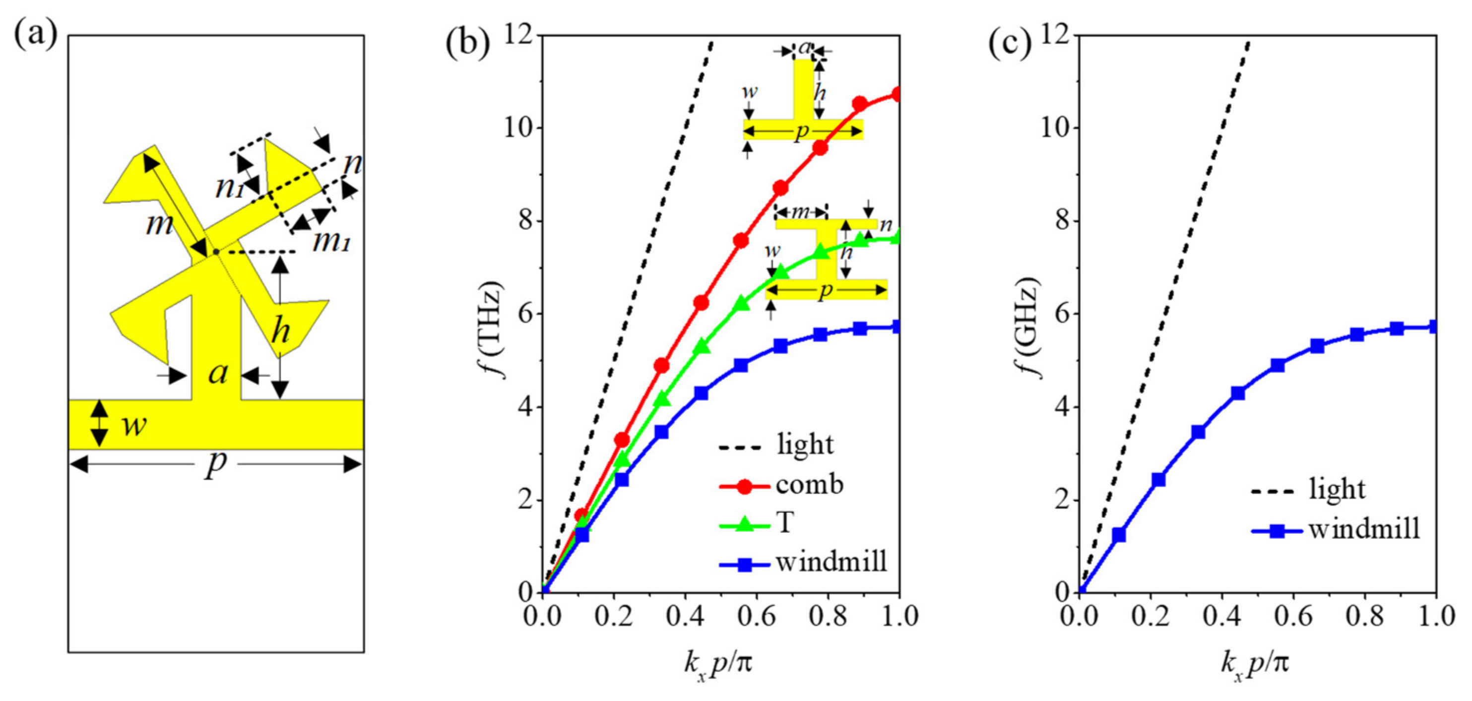
Figure 2.
The dependence of the dispersion relations on the geometric parameters of the windmill-shaped SSPP unit. (a) Terahertz windmill-shaped SSPP unit’s dispersion relations for m when n1 is fixed at 1 μm; (b) terahertz windmill-shaped SSPP unit’s dispersion relations for n1 when m is fixed at 2.5 μm; (c) microwave windmill-shaped SSPP unit’s dispersion relations for m when n1 is fixed at 1 mm; (d) microwave windmill-shaped SSPP unit’s dispersion relations for n1 when m is fixed at 2.5 mm.

Figure 3.
Schematic diagram of the proposed windmill-shaped SSPP waveguide with conversions, where l1 = 5 μm, l2 = 70 μm, l3 = 60 μm, w1 = 20 μm.
Figure 3.
Schematic diagram of the proposed windmill-shaped SSPP waveguide with conversions, where l1 = 5 μm, l2 = 70 μm, l3 = 60 μm, w1 = 20 μm.

Figure 4.
Simulated S-parameters of the terahertz windmill-shaped SSPP waveguide.
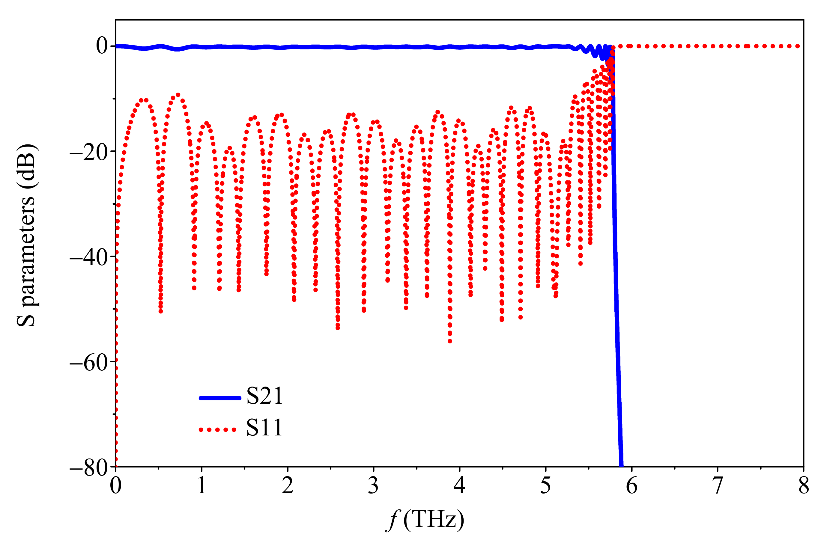
Figure 5.
Simulated electric field magnitude (|E|) distributions propagating along the x-direction at (a) 5 THz and (b) 6 THz on the xoy plane of the terahertz windmill-shaped SSPP waveguide.
Figure 5.
Simulated electric field magnitude (|E|) distributions propagating along the x-direction at (a) 5 THz and (b) 6 THz on the xoy plane of the terahertz windmill-shaped SSPP waveguide.
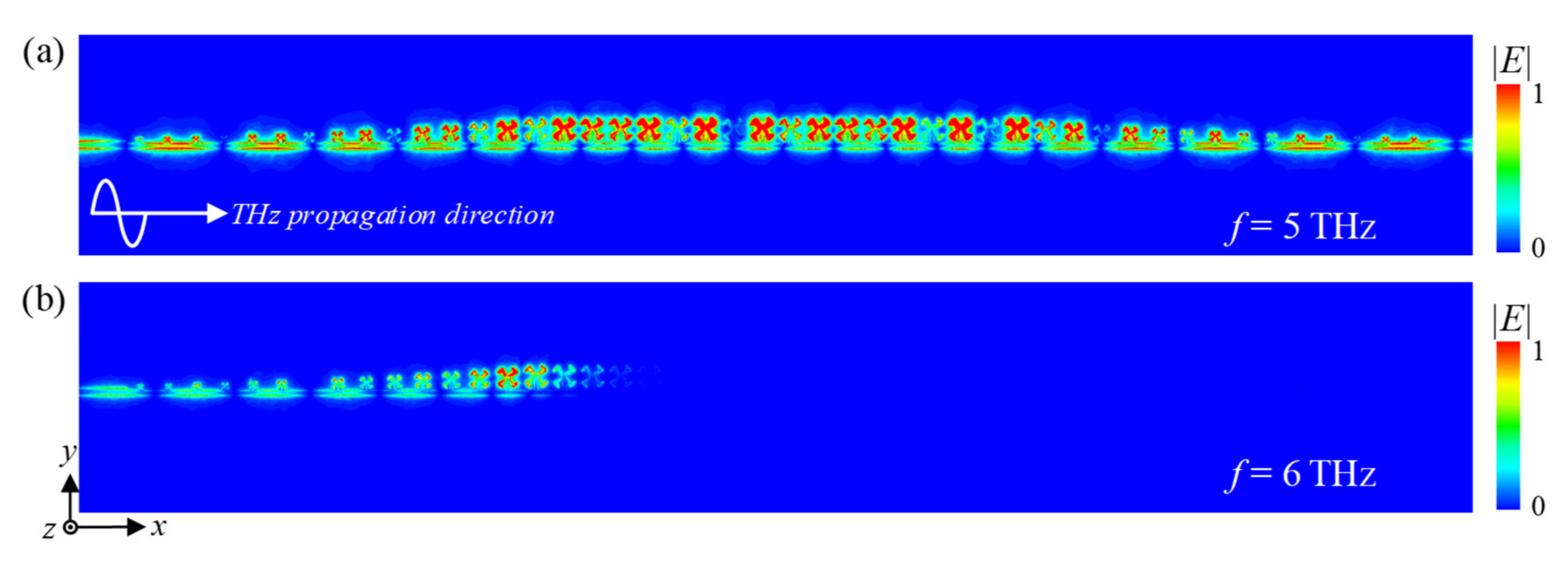
Figure 6.
Microwave waveguide prototype and S parameters. (a) Fabricated microwave windmill-shaped SSPP waveguide prototype; (b) simulated and measured S parameters of the SSPP waveguide prototype.
Figure 6.
Microwave waveguide prototype and S parameters. (a) Fabricated microwave windmill-shaped SSPP waveguide prototype; (b) simulated and measured S parameters of the SSPP waveguide prototype.

Figure 7.
Homemade microwave near-field scanning system and the field distributions of the microwave SSPP waveguide. (a) Photograph of the homemade microwave near-field scanning system; (b–e) simulated and measured electric field Ez distributions of the microwave windmill-shaped SSPP waveguide on the xoy plane at z = 1 mm at 5 GHz and 6 GHz, respectively.
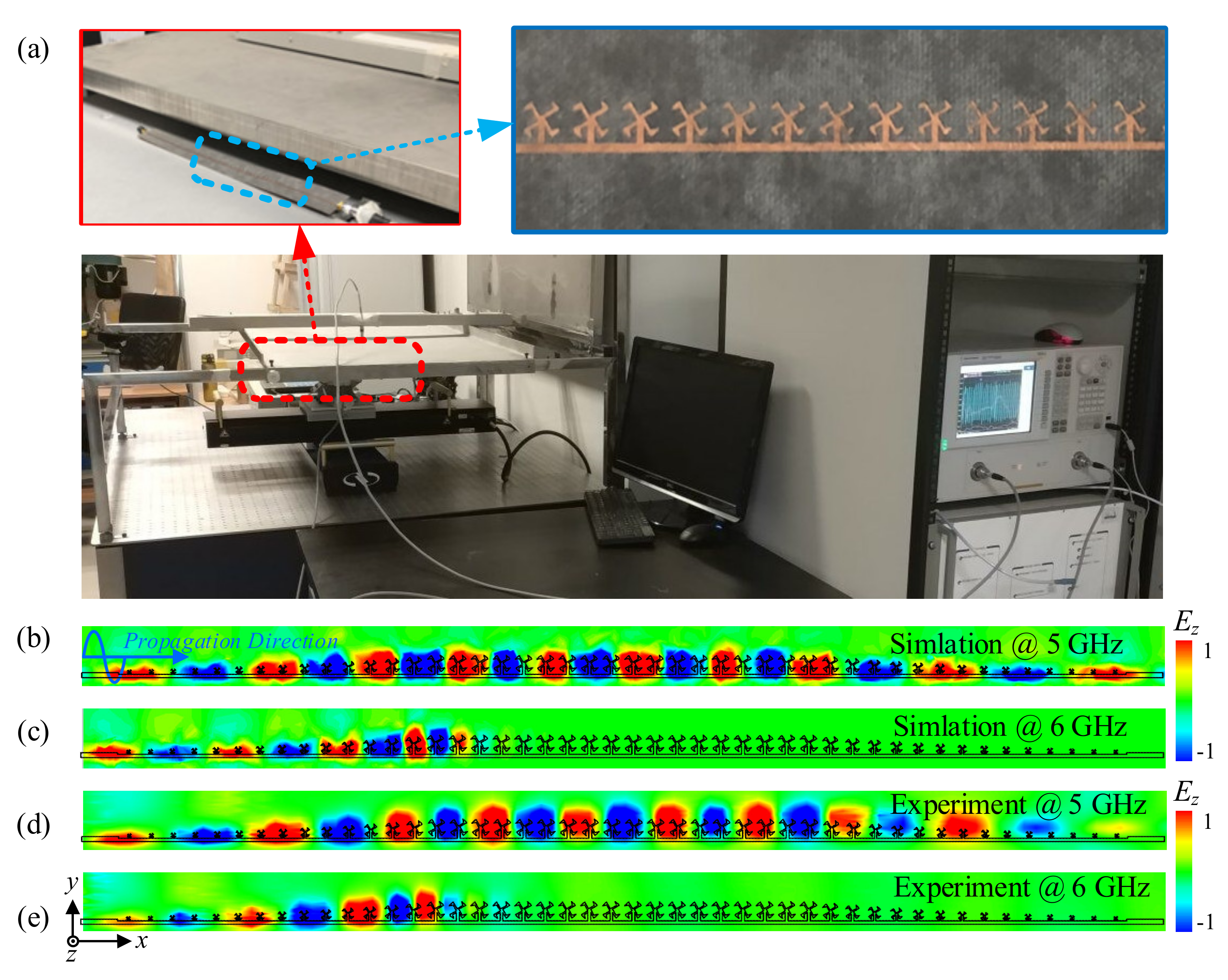
Figure 8.
Measured S-parameters of the microwave windmill-shaped SSPP waveguide under different bend angles θ = 0°, 30°, 60°, 90°, 120°, and 150°.
Figure 8.
Measured S-parameters of the microwave windmill-shaped SSPP waveguide under different bend angles θ = 0°, 30°, 60°, 90°, 120°, and 150°.

Publisher’s Note: MDPI stays neutral with regard to jurisdictional claims in published maps and institutional affiliations. |
© 2022 by the authors. Licensee MDPI, Basel, Switzerland. This article is an open access article distributed under the terms and conditions of the Creative Commons Attribution (CC BY) license (https://creativecommons.org/licenses/by/4.0/).
Share and Cite
MDPI and ACS Style
Wang, Z.; Feng, H.; Yang, X.; Xu, X.; Zheng, Y.; Ye, L. A Windmill-Shaped SSPP Waveguide for High-Efficiency Microwave and Terahertz Propagation. Electronics 2022, 11, 1293. https://doi.org/10.3390/electronics11091293
AMA Style
Wang Z, Feng H, Yang X, Xu X, Zheng Y, Ye L. A Windmill-Shaped SSPP Waveguide for High-Efficiency Microwave and Terahertz Propagation. Electronics. 2022; 11(9):1293. https://doi.org/10.3390/electronics11091293
Chicago/Turabian StyleWang, Zhihui, Hao Feng, Xiaofan Yang, Xiong Xu, Yunxing Zheng, and Longfang Ye. 2022. "A Windmill-Shaped SSPP Waveguide for High-Efficiency Microwave and Terahertz Propagation" Electronics 11, no. 9: 1293. https://doi.org/10.3390/electronics11091293
Note that from the first issue of 2016, this journal uses article numbers instead of page numbers. See further details here.