
Machine Learning Based Interference Mitigation for Intelligent Air-to-Ground Internet of Things


1
China Telecom Research Institute, Beijing 100191, China
2
Institute of Information Engineering, North China University of Technology, Beijing 100144, China
3
School of Computer Science, Beijing University of Posts and Telecommunications, Beijing 100876, China
*
Author to whom correspondence should be addressed.
Electronics 2023, 12(1), 248; https://doi.org/10.3390/electronics12010248
Submission received: 5 November 2022
/
Revised: 21 December 2022
/
Accepted: 29 December 2022
/
Published: 3 January 2023
(This article belongs to the Section Networks)
Abstract
:With the continuous development of the Internet of things (IoT) technology, the air-to-ground (ATG) system has attracted more and more attention. The system will effectively increase communication coverage and improve communication quality. The ATG system uses frequency reuse technology in the ground layer to further utilize frequency resources. This paper focuses mostly on the cochannel interference between the 5G BS and the ATG airborne CPE terminal in the 3.5 GHz range. The ATG airborne CPE terminal has to be further isolated from 5G BS in order to prevent interference. We must manage the transmitting power of the ATG airborne CPE terminal in order to comply with the additional isolation criteria. The RSRP value of 5G BS determines the transmit power of the ATG airborne CPE terminal. We creatively suggested a machine learning (ML) approach based on multihead attention to anticipate the RSRP of 5G BS because it is highly challenging for the ATG aerial CPE terminal to monitor the RSRP of 5G BS in real time. By comparing the suggested ML-based approach with the actual measured values, its efficacy is confirmed.
1. Introduction
With the continuous progress of science and technology, the computing and sensing capabilities of the Internet of things (IoT) are constantly improving [1]. This enables the IoT to complete information transfer and the same control between different devices even without manual supervision [2]. Through the fully intelligent remote management system, a large number of intelligent devices are connected to each other, which means that the IoT has become an important part of the future Internet technology and can bring great benefits to industrial production and economic growth. Therefore, IoT technology has received more and more attention from academia and industry [3].
The premise of large-scale coverage of the IoT often requires a large number of ground-supporting facilities, which means that the increase in construction costs and the uncertainty of the operating environment make this solution difficult to achieve in terms of economic costs. Unmanned aerial vehicle (UAV) communication in the air is easier to connect to ground customers through LoS links, and UAV communication has the characteristics of long distance and high reliability [4]. As a solution, UAV communication is introduced into the current network architecture as a supplement to effectively alleviate the above problems. Compared with the original scheme, UAV is easier to deploy dynamically according to changes than ground facilities, and is more robust to different environments. At the same time, because the UAV has no site requirements and does not require the cable of the tower, the economic cost is lower. A large number of UAVs can build multi-UAV networks to increase coverage [5]. Due to high flexibility and simpler configuration, multi-UAV networks are an effective solution to quickly restore and improve the quality of communication networks [6].
To further enhance the application of IoT with different service functions in scenarios, the specific advantages of each networking paradigm need to be exploited [7]. For example, satellite communication systems can be used to provide wide coverage and seamless connectivity in sparsely populated and remote areas. In urban areas, ground networks can be densely deployed to support high-speed data transmission, UAV communication can be used to supplement the existing network structure in areas with extremely crowded populations, thereby improving communication efficiency [8]. From the perspective of existing technologies, a simple single network cannot process the IoT in time. The massive data and access requests generated by big data have become the consensus of scholars. Because of the demand for diversified networks, the integrated network architecture that integrates space-based networks, air-based networks, and ground-based networks is attracting more and more scholars’ attention. This paper focuses on the fusion of air-based and ground-based networks, namely creating the ATG network [9].
The ATG is used more frequently than it was before becuse it has a faster transmission rate, a lower economic cost, and a greater communication quality. The ATG system and terrestrial mobile communication systems’ interference has previously been investigated and evaluated by several academics. In order to make full use of the limited spectrum, the ATG system works at the same frequency as the ground 5G, but the interference problem when the system works has not been fully studied by relevant scholars. The frequency reuse of terrestrial mobile communication system and ATG system is the focus of this paper. The interference between aerial 5G ATG client equipment and ground-based 5G systems in the 3.5 GHz frequency region is also investigated.
The contributions of this paper are as follows. This paper mainly studies the cochannel interference of ATG airborne CPE terminal and 5G BS in the 3.5 GHz band. In order to ensure that ATG airborne CPE terminal does not interfere with 5G BS, additional isolation needs to be set between ATG airborne CPE terminal and 5G BS. In order to meet the requirements of additional isolation, we need to control the sending power of ATG airborne CPE terminal. The transmit power of ATG airborne CPE terminal is determined by the RSRP value of 5G BS. It is very difficult for the ATG airborne CPE terminal to track the RSRP of 5G BS in real time, so we innovatively proposed a machine learning (ML) method based on multihead attention to predict the RSRP of 5G BS. The effectiveness of the proposed ML-based method is verified by comparing it with the actual measured values.
The structure of this article is as follows. The system model is introduced in Section 2. Section 3 provides an evaluation approach for interference. In Section 4, the power control mechanism of ATG CPE based on ML is developed in order to prevent interference caused by ATG CPE. Section 5 contains the numerical analysis, and Section 6 contains the conclusions.
2. System Model
By using dependable land mobile communication technology, ATG develops customized solutions for aircraft high-speed mobile, broad coverage, and other attributes. It builds a specialized ground-based system that can cover the sky and a dedicated ground–air three-dimensional coverage network that can effectively address the issue of high-altitude three-dimensional coverage in order to achieve high-speed data transfer between ground and air. The ground BS solution closely follows the development of mobile communication technology, provides high-bandwidth, high-flow, and cost-effective solutions, and has substantial advantages in network setup and upkeep. Airline passengers flying with ATG services can take use of in-flight entertainment, in-flight work areas, specialized services, and a wide range of industrial application options.
The key elements of ATG, including the ground and air networks, are shown in Figure 1. These two network components can function separately or together. By integrating the heterogeneous networks between the two network segments, a hierarchical wireless network can be easily built. Terrestrial networks, consisting of cellular wireless networks and processing centers, have high data rates but cannot reach rural and remote areas. The air network is an air mobile system based on aircraft, with drones, aircraft, balloons, etc. Communication services improve the ground network. Compared with cellular wireless networks, aerial networks are more adaptable, have a lower cost, provide wider service coverage, and provide regional wireless access.
Because ATG airborne CPE terminals use the same frequency network as 5G BS, the ground transmission from ATG airborne CPE terminals has the potential to negatively impact the current ground-deployed 5G systems as shown in Figure 1. In order to maximize the communication quality and information transmission rate, the ATG system and 5G system use the same operating frequency. As a result, the major focus of this research is on the interference caused by ATG airborne CPE to ground-based 5G system BS employing 3.5 GHz frequency band transmission at various flight altitudes and cell arrangements.
The specifications of the 5G mobile communication technology are also shown in Table 1. Table 2 lists the ATG airborne terminal characteristics used in the cochannel interference compatibility study based on how the ATG system is used in the real world. Because of the aircraft’s flight height, the ground–air path clutter loss calculation method uses the free space propagation model of ITU-R P.525 and ITU-R P.2108 ground–air path clutter loss, in which 50% of the position percentage is chosen, to account for the ATG airborne CPE terminal’s potential to interfere with another cofrequency or adjacent frequency systems [10,11,12,13].
3. Interference Evaluation Method
When the system works, the 3.5 GHz frequency band has a certain probability of being interfered by the ATG airborne CPE terminal and the ground 5G BS, as shown in Figure 2. This is mainly because the CPE terminal and the 5G BS both work at the 3.5 GHz frequency. It is crucial to do new research to determine how effectively the 5G system integrates with ATG. During the interference analysis process, it is important to consider the worst-case scenario in which the airborne CPE uplink transmission interferes with the ground-based 5G BS using the same frequency, i.e., the ground-based 5G BS antenna panel is pointed in the general direction of the ATG air-borne CPE antenna’s peak power.
The ATG airborne CPE terminal will interfere with the 5G BS when it is receiving signals; thus it is vital to determine the maximum isolation needed for the 5G BS to be free from ATG signal interference. The calculation formula for isolation is as follows,
where transmitting power of ATG airborne CPE terminal, is the array ohmic loss, is the minimum coupling loss, is the earth-space clutter loss, is the maximum allowed interference.
is given by
where is the antenna gain of ATG airborne terminal, is the antenna gain of 5G BS, and is the free space pathloss. Let denote the carrier frequency and denote the distance between the ATG airborne CPE terminal and 5G BS; then we can get
We can get by ITU-R P.2108 as
where is the clutter loss, is the angle from 5G BS to ATG airborne CPE terminal and is the inverse normal distribution, , .
The formula for calculating is as follows,
where is the interference threshold between the ATG airborne CPE terminal and the 5G BS, is the natural noise floor of the 5G BS. Let denote the sensitivity deterioration margin, and then we can get by
Let denote the noise factor of 5G BS and denote the channel bandwidth, we can get by
4. Power Control Method of ATG CPE Based on ML
4.1. Prediction Method of Time Series Based on ML
Transformers is a framework that proposed to help define sequences clearly [14]. It consists of an encoder module and a decoder module that each include many encoders and decoders with the same design, as shown in Figure 3. Each encoder and decoder is made up of a feed-forward neural network, a self-attention layer, and an encoder–decoder attention layer for the decoder.
4.1.1. Self-Attention Layer
, , are three parts of the input transform of the self-attention layer. and represent input, query (key), dimension, and sequence length, respectively. The scaled dot-product attention is applied on . The process of calculating the attention function is as follows (left as shown in Figure 3).
- Step 1: When calculating the fraction between specific vectors, the following formula is used: .
- Step 2: In normalizing the fraction of gradient stability, the following formula is used: .
- Step 3: Later, when converting scores to probabilities, the softmax function is used to process them .
- Step 4: The weighted value matrix obtained is .
The computational process can be summarized as
Simple logic underlies (8). The scores that are computed in Step 1 between two separate vectors are what decide how much attention is paid to other words while encoding the word in its present place. In step 2, the scores are normalized to increase gradient stability for better training, and in step 3, the values are converted to probabilities. The total of the probabilities is then multiplied by each value vector. The subsequent layers place more emphasis on vectors with higher probabilities.
In addition to the following cases, because the encoder module is the source of the key matrix K and the value matrix V, the previous layer is the source of the query matrix Q. The self-attention layer in the encoder module and the encoder–decoder attention layer in the decoder module are not the same.
It can be seen from the above that because the prior technology cannot affect the order of words, the self-attention layer cannot identify the position of words. This problem can be solved by embedding the -dimensional position encoding into the initial input to obtain the final vector [15]. The coding position is as follows,
where indicates a word’s place in a phrase, and stands for the positional encoding’s current dimension.
4.1.2. Multihead Attention
Through multiheaded attention, the ability of the self-attentive layer is continuously increased, and when performing reading, we focus on one or more words, including the reference word, shifting attention from other important locations at the same time, a process determined by the single-headed, self-attentive layer, specifically, the attention layer completes the process by continuously receiving various representation subspaces [16]. After training, the query, key and value matrix project the input vector into the subspace, and generate output in the linear layer [17]. Multiple self-attention heads divide queries, keys, and values into h blocks, and multiple self-attention heads complete the attention function in parallel, and synthesize each output value to form the final output.
4.1.3. Other Key Concepts in Transformer
As shown in Figure 3, which demonstrates the presence of residual connections, residual connections in each sublayer of the encoder and decoder enhance the flow of information and improve performance, followed by the normalization of the layer, the procedures are described as where, is the input to the attention layer. This is because the query, key, and value matrices Q, K, and V have the same source matrix X.
The network composed of a nonlinear activation function and two linear conversion layers and applied after the self-attention layer of the encoder and decoder is called a feed-forward network (FFN), which can be expressed as
where and represent the parameter matrices in the transformation layers, and σ represents the nonlinear activation function.
Finally, in the decoder, the stack of vectors is rotated by using the decoder’s last layer. A linear layer and a softmax layer are used to accomplish this. The vector is projected into a logits vector via the linear layer. The logits vector is then converted into probabilities by using the softmax layer.
4.2. Power Control Method
In order to minimize interference, the air ATG CPE power control technology based on the ML model is adopted. Specifically, the ground BS signal is monitored and the reference signal receiving power (RSRP) is recorded by airborne ATG CPE. It is assumed that the n RSRP value of the maximum BS can be tracked by the aerial ATG CPE. We have
where represents the time series of 5G BS RSRP received by flight terminal. The sequence is
where is the length of time series and is the current time. When the value of is obtained from the environment of the same time-frequency unit and the power of the flight terminal, is the 5G BS RSRP power device, and the estimated interference is
Then we can know
By using ML model to predict time series, we have . Procedure 1 represents the training process of the ML model, where the inputs are
and output
By setting the 5G BS to . for time-frequency interference, the combined vector is
As demonstrated from the examples above, the ATG CPE’s transmission power control bias may be configured to
when , elimination of interference power control is not necessary. When , transmission power can be adjusted. We have
The 5G BS will be better protected against interference if the prediction length is chosen for a higher value. However, if prediction accuracy declines, it will result in needless power discrimination on the part of the ATG CPE and impair the uplink functionality of the ATG network. ATG CPE’s decision-making time will be reduced for lower values, and there may be an increased possibility of 5G BS interference. Consequently, an adequate value will also impact how well the algorithm performs.
4.3. Training Process of ML Model
| Training Process 1: The Power Control Training Process of ATG CPE Based on ML |
| Input: Iterations , A neural network consist of Encoder and Decoder, Datasets , Output: Neural network parameters Initialize ,Embedding vector , which and contain the interference estimation embedding and the sequence position embedding for from to : Encoder:
|
5. Numerical Analysis
5.1. Analysis of Cofrequency Interference
In this part, two typical 5G BS deployment scenarios—the urban macro BS and the rural macro BS—are analyzed. Deterministic computing coexistence study is also performed. The airborne CPE transmission power for the 3.5 GHz ATG interference system is 26 dBm, and the maximum antenna gain is 20.0515 dBi. The model makes use of the ITU-R P.2108 clutter loss and the free space propagation model. The troubled 5G system’s BS antenna model adheres to the ITU-R M.2101 standard. When evaluating, the urban scene’s antenna downtilt angle is 6°, the rural scene’s is 3°, and the highest antenna gain is 24.46 dBi. The ATG aircraft’s flight height is adjusted to 3 km and 10 km, respectively, depending on the particular requirements of certain scenarios. Figure 4 and Figure 5 illustrate the computation of the extra isolation from interference for various horizontal separations between the aircraft and the 5G BS.
In order to analyze the scenario of 5G system BS reception with airborne CPE cochannel interference. In Figure 5, the interference isolation’s deterministic calculation results are displayed. The findings demonstrate that the extra isolation needed by the two systems varies dramatically under various application situations, varying horizontal distances, and varying flight altitudes.
When studying the ATG system in an urban environment, the two systems are identical when the flying height is 3 km. Additional isolation of 0.05–20 dB is needed to lower interference. To prevent interference, an extra 0.85–6.7 dB isolation is needed when the flying altitude is 10 km. The two systems require an extra 0.54–20 dB of separation in a rural environment when the flying height is 3 km in order to prevent interference. The extra isolation is 0.55–8.58 dB when the flying height is 10 km to prevent interference.
Figure 6 and Figure 7 show that the ATG system is affected by the flight altitude and horizontal position in different environments and similarly obtains additional isolation required for ATG and 5G systems near 3.5 GHz. Assuming all other factors remain constant and taking into account the worst-case scenario for signal transmission, the higher the altitude at which the aircraft carrying the ATG system flies, the simpler the two systems become. When the vertical height is fixed, the maximum interference point of the ATG system is closer to the BS.
5.2. Analysis of the Performance of Power Control Method of ATG CPE Based on ML
Figure 8 and Figure 9 show the situation between the actual measured interference and the predicted interference in urban and rural, respectively. We can see that due to the time-varying characteristics of the channel, the interference from the ATG airborne CPE terminal to the 5G BS changes dynamically depending on whether one is in an urban or rural environment. Therefore, in order not to interfere with the 5G BS, the ATG airborne CPE terminal cannot use a fixed transmission power for data transmission. The ATG airborne CPE terminal needs to dynamically adjust its transmit power according to channel characteristics. By observing Figure 8 and Figure 9, we can see that the predicted values of the proposed algorithm can fit the actual measured values very well. Thus, Figure 8 and Figure 9 demonstrate the effectiveness of our proposed ML-based algorithm.
6. Conclusions
This paper studied the cochannel interference between the ATG airborne CPE terminal and 5G BS in the 3.5 GHz frequency band. In order to ensure that the ATG airborne CPE terminal does not interfere with the 5G BS, additional isolation needs to be set between the ATG airborne CPE terminal and the 5G BS. In this paper, we controlled the transmit power of the ATG airborne CPE terminal to meet the requirement of additional isolation. Based on the above reasons, we proposed a multihead attention-based ML method to predict the RSRP of 5G BS. Then the transmit power of ATG airborne CPE terminal can be determined by the predicted RSRP value. The effectiveness of the proposed ML-based method was verified by comparison with actual measurements.
Author Contributions
Writing—original draft preparation, L.L.; writing—review and editing, C.L.; validation, Y.Z. All authors have read and agreed to the published version of the manuscript.
Funding
This work was supported by the National Key R&D Program of China (No. 2020YFB1806700).
Data Availability Statement
Data is unavailable due to privacy.
Conflicts of Interest
The authors declare no conflict of interest.
References
- Tran-Dang, H.; Krommenacker, N.; Charpentier, P.; Kim, D.S. Toward the IoT for Physical Internet: Perspectives and Challenges. IEEE Internet Things J. 2020, 7, 4711–4736. [Google Scholar] [CrossRef]
- Anthi, E.; Williams, L.; Słowińska, M.; Theodorakopoulos, G.; Burnap, P. A supervised intrusion detection system for smart home IoT devices. IEEE Internet Things J. 2019, 6, 9042–9053. [Google Scholar] [CrossRef]
- Shafique, K.; Khawaja, B.A.; Sabir, F.; Qazi, S.; Mustaqim, M. IoT (IoT) for next-generation smart systems: A review of current challenges, future trends and prospects for emerging 5G-IoT scenarios. IEEE Access 2020, 8, 23022–23040. [Google Scholar] [CrossRef]
- Liu, L.; Zhang, S.; Zhang, R. Multi-Beam UAV Communication in Cellular Uplink: Cooperative Interference Cancellation and Sum-Rate Maximization. IEEE Trans. Wirel. Commun. 2019, 18, 4679–4691. [Google Scholar] [CrossRef] [Green Version]
- Zeng, Y.; Wu, Q.; Zhang, R. Accessing from the sky: A tutorialon UAV communications for 5G and beyond. Proc. IEEE 2019, 107, 2327–2375. [Google Scholar] [CrossRef] [Green Version]
- Mozaffari, M.; Saad, W.; Bennis, M.; Nam, Y.-H.; Debbah, M. A tutorial on UAVs for wireless networks: Applications, challenges, and open problems. IEEE Commun. Surv. Tutor. 2019, 21, 2334–2360. [Google Scholar] [CrossRef] [Green Version]
- Hong, T.; Zhao, W.; Liu, R.; Kadoch, M. Space-air-ground IoT network and related key technologies. IEEE Wirel. Commun. 2020, 27, 96–104. [Google Scholar] [CrossRef]
- Guo, H.; Li, J.; Liu, J.; Tian, N.; Kato, N. A survey on space-airground-sea integrated network security in 6G. IEEE Commun. Surv. Tutor. 2022, 24, 53–87. [Google Scholar] [CrossRef]
- Liu, J.; Shi, Y.; Fadlullah, Z.M.; Kato, N. Space-air-ground integrated network: A survey. IEEE Commun. Surv. Tutor. 2018, 20, 2714–2741. [Google Scholar] [CrossRef]
- Recommendation ITU-R M.2101-0, Modeling and Simulation of IMT Networks and Systems for Use in Sharing and Compatibility Studies; ITU: Geneva, Switzerland, 2017.
- ITU-R Recommendation P.525-4, Calculation of Free-Space Attenuation; ITU: Geneva, Switzerland, 2019.
- ITU-R Recommendation P.2108-1, Prediction of Clutter Loss; ITU: Geneva, Switzerland, 2021.
- ITU-R Document 5D/716-E, “Characteristics of Terrestrial Component of IMT for Sharing and Compatibility Studies in Preparation for WRC-23,” in Geneva; ITU: Geneva, Switzerland, 2021.
- Vaswani, A.; Shazeer, N.; Parmar, N.; Uszkoreit, J.; Jones, L.; Gomez, A.N.; Kaiser, Ł.; Polosukhin, I. Attention is all you need. In Proceedings of the 31st Conference on Neural Information Processing System, Long Beach, CA, USA, 4–9 December 2017. [Google Scholar]
- Dufter, P.; Schmitt, M.; Schütze, H. Position information in transformers: An overview. Comput. Linguist. 2022, 48, 733–763. [Google Scholar] [CrossRef]
- Loh, S.B.; Roy, D.; Fernando, B. Long-term Action Forecasting Using Multi-headed Attention-based Variational Recurrent Neural Networks. In Proceedings of the IEEE/CVF Conference on Computer Vision and Pattern Recognition, New Orleans, LA, USA, 19–20 June 2022; pp. 2419–2427. [Google Scholar]
- Ba, J.L.; Kiros, J.R.; Hinton, G.E. Layer normalization. arXiv 2016, arXiv:1607.06450. [Google Scholar]
Figure 1.
An architecture for ATG network.
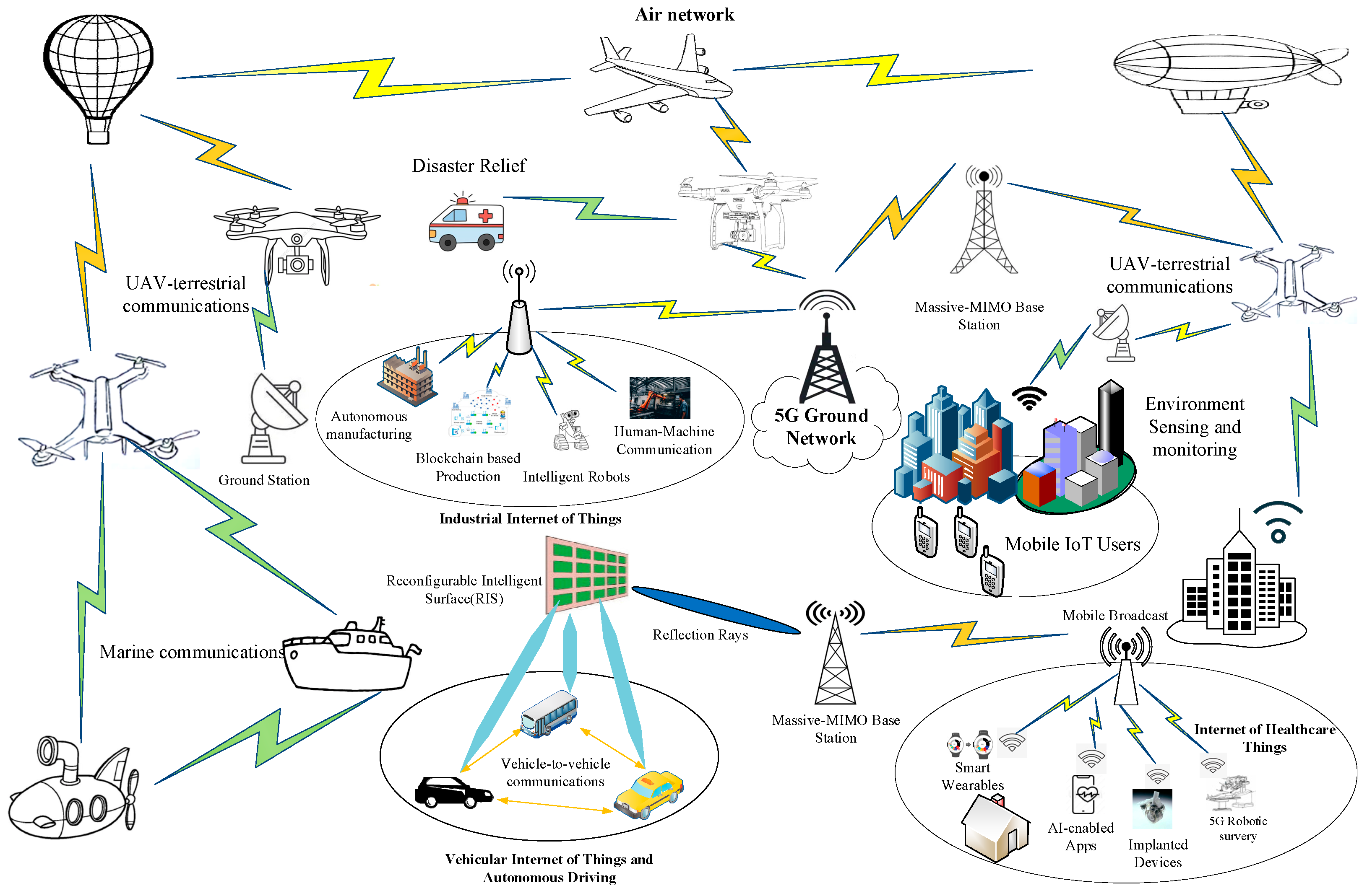
Figure 2.
Cofrequency interference between ATG and 5G.
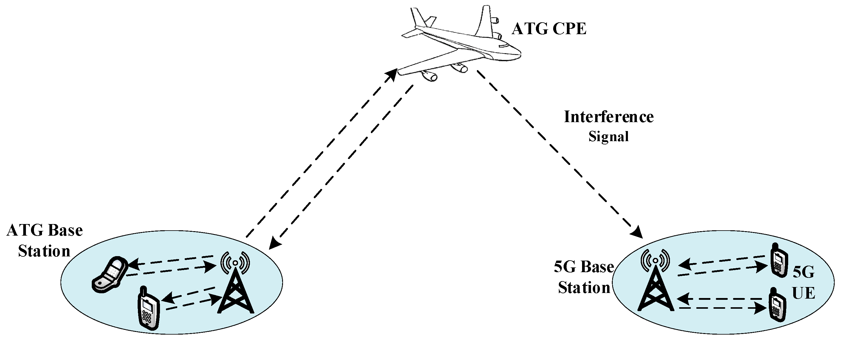
Figure 3.
Transformers architecture to efficiently model sequences.

Figure 4.
Additional isolation of urban vs. rural (3 km).
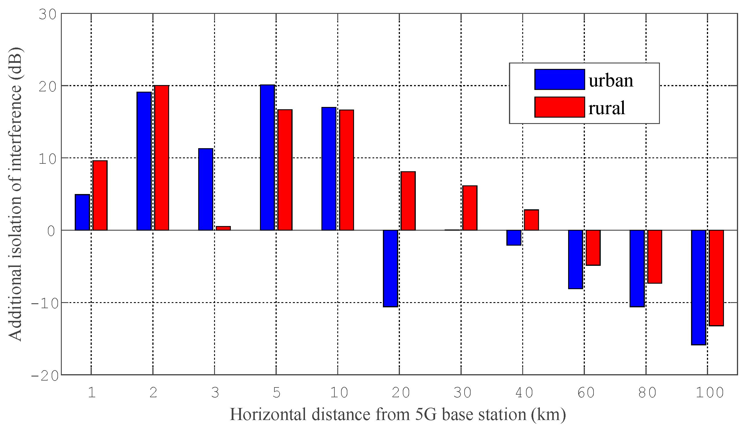
Figure 5.
Additional isolation of urban vs. rural (10 km).
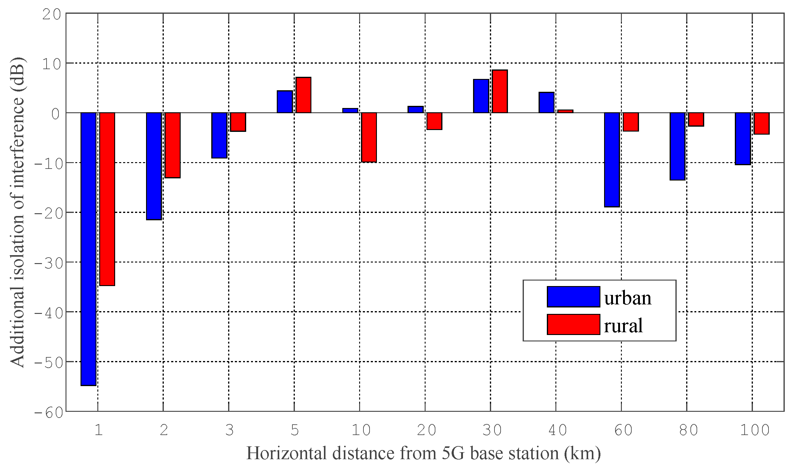
Figure 6.
Additional isolation for 5G and ATG (urban).
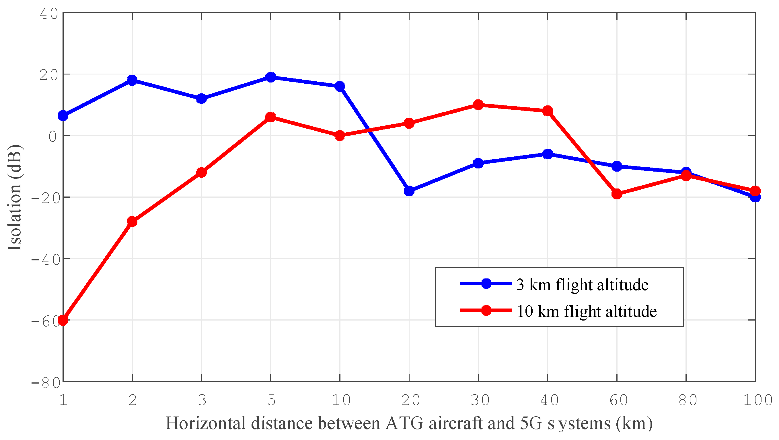
Figure 7.
Additional isolation for 5G and ATG (rural).

Figure 8.
ML-based interference prediction (urban).
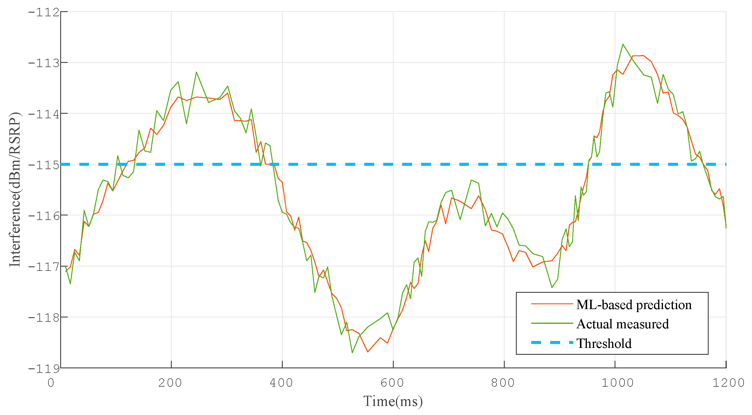
Figure 9.
ML-based interference prediction (rural).


Table 1.
ATG Airborne Terminal Parameters.
| Parameter | Value |
|---|---|
| Frequency Band | 3.5 GHz |
| Network configuration | TDD |
| Channel bandwidth | 100 MHz |
| ATG area radius | 100 km |
| Maximum transmitting power | 26 dBm |
| Element gain | 5 dBi |
| Antenna altitude | 3~10 km |
Table 2.
5G Mobile Communication System Parameters.
| Parameter | Value | |
|---|---|---|
| Frequency band | 3.5 G | |
| TDD/FDD | TDD | |
| Typical channel bandwidth | 100 MHz | |
| Scenario | Rural | Urban |
| Element gain | 6.4 dBi | 6.4 dBi |
| Mechanical downtilt | 3° | 6° |
| Antenna height | 35 m | 20 m |
| Cell radius | 1.6 km | 0.4 km |
| Sectorization | 3 sectors | |
| Antenna pattern | Recommendation ITU-R M. 2101 | |
| Horizontal/vertical 3 dB beam width | 90° for H, 65° for V | |
| Horizontal/vertical front to back ratio | 30 dB | |
| Antenna polarization | ±45° | |
| Antenna array configuration | 4 × 8 | |
| Array Ohmic loss | 2 dB | |
| Protection criterion (I/N) | −6 dB | |
| Noise temperature | 290 K | |
| Receiver noise level (10logKT B) | −109 dBm/MHz | |
| Noise figure | 5 dB | |
| Receiver protection threshold | −115 dBm/MHz | |
Disclaimer/Publisher’s Note: The statements, opinions and data contained in all publications are solely those of the individual author(s) and contributor(s) and not of MDPI and/or the editor(s). MDPI and/or the editor(s) disclaim responsibility for any injury to people or property resulting from any ideas, methods, instructions or products referred to in the content. |
© 2023 by the authors. Licensee MDPI, Basel, Switzerland. This article is an open access article distributed under the terms and conditions of the Creative Commons Attribution (CC BY) license (https://creativecommons.org/licenses/by/4.0/).
Share and Cite
MDPI and ACS Style
Liu, L.; Li, C.; Zhao, Y. Machine Learning Based Interference Mitigation for Intelligent Air-to-Ground Internet of Things. Electronics 2023, 12, 248. https://doi.org/10.3390/electronics12010248
AMA Style
Liu L, Li C, Zhao Y. Machine Learning Based Interference Mitigation for Intelligent Air-to-Ground Internet of Things. Electronics. 2023; 12(1):248. https://doi.org/10.3390/electronics12010248
Chicago/Turabian StyleLiu, Lei, Chaofei Li, and Yikun Zhao. 2023. "Machine Learning Based Interference Mitigation for Intelligent Air-to-Ground Internet of Things" Electronics 12, no. 1: 248. https://doi.org/10.3390/electronics12010248
Note that from the first issue of 2016, this journal uses article numbers instead of page numbers. See further details here.