Article

A Quad-Band Shared-Aperture Antenna Based on Dual-Mode Composite Quarter-Mode SIW Cavity for 5G and 6G with MIMO Capability

by
Amjaad T. Altakhaineh
1,
Saqer S. Alja’afreh
1,*,
Aser M. Almatarneh
1,
Eqab Almajali
2,
Luae Al-Tarawneh
3 and
Jawad Yousaf
4
1
Electrical Engineering Department, Mutah University, Al-Karak 61710, Jordan
2
Electrical Engineering Department, University of Sharjah, Sharjah 27272, United Arab Emirates
3
Communications Engineering Department, Princess Sumaya University for Technology, Amman 11941, Jordan
4
Electrical, Computer, and Biomedical Engineering Department, Abu Dhabi University, Abu Dhabi 59911, United Arab Emirates
*
Author to whom correspondence should be addressed.
Electronics 2023, 12(11), 2480; https://doi.org/10.3390/electronics12112480
Submission received: 6 May 2023 / Revised: 23 May 2023 / Accepted: 24 May 2023 / Published: 31 May 2023
(This article belongs to the Special Issue Advanced Antenna Design for 5G and beyond Communications)

Abstract

:
This study introduces a new design for an ultra-compact shared-aperture antenna utilizing a quarter-mode substrate integrated waveguide (QMSIW) cavity. The proposed antenna operates as a 4 × 4 multi-input multi-output (MIMO) system in three 5G/6G millimeter-wave (MMw) bands, while functioning as a single element antenna for a 5.5 GHz wireless fidelity Microwave (Mw) band. The antenna comprises four QMSIW cavity resonators; each QMSIW is loaded with dual slots to produce tri-band MMw operation at 28 GHz, 38 GHz, and 0.13 THz. The four cavities are arranged to reuse the entire aperture by creating a conventional open-loop antenna that operates at a frequency of 5.5 GHz. Simulation, measurement, and co-simulation results show that the proposed antenna has a quad-band operation and exhibits favorable characteristics. The measured scattering parameters validate the simulated ones over the four bands under consideration. The lowest values of the measured total radiation efficiencies are 80%, 73%, 62%, and 72% (co-simulation) within the four covered bands, respectively. The antenna peak gains are 1.8 to 1.85 dBi, 4.0 to 4.5 dBi, 4.3 to 4.5 dBi, and 6.5 to 6.6 dBi within the covered bands. Furthermore, the design satisfies MIMO and diversity conditions (envelope correlation coefficient and branch power ratio) over frequency bands of operation. All excellent results are achieved from an ultra-compact size in terms of footprint area (0.018 λ 0 2 ), where λ0 represents the free space wavelength at 5.5 GHz. The antenna boasts an excellent reuse aperture utilization efficiency (RAU) of 92% and a large ratio frequency of 23, making it an ideal candidate for compact devices. With its superior performance, the proposed design is well-suited for a range ofs wireless communication systems, including mobile devices and the Internet of Things.

1. Introduction

Recently, several new wireless applications and emerging technologies such as Internet of Things (IoT), artificial intelligence (AI), and smart systems have been deployed commercially over 5G networks. The current 5G wireless networks are known as heterogeneous networks, which are designed to operate in both microwave (Mw) and millimeter-wave (MMw) frequency bands simultaneously. Mw bands such as sub-6 GHz provide good far-field coverage for long-range applications, while MMw new radio frequency bands, which are defined by the 3rd Generation Partnership Project (3GPP), allow for high-gain beams. As an example, the n257 band (26.5–29.5 GHz) offers high-gain pencil beams that enable high data rates [1,2]. The success of 5G has motivated researchers to investigate instant wireless services and connectivity, leading to the expected launch of 6G mobile systems around 2030 [1,2]. Such 6G mobile systems are expected to allow a shift towards upper MMw frequencies above 100 GHz, primarily in the terahertz band, which is divided into two regions: sub-terahertz (sub-THz) (0.1–0.3 THz) and terahertz (THz) region (0.3–10 THz) [3,4,5,6]. This advanced feature may allow 6G technology to support data rates of around 1 Tbps and lower the latency by 1 microsecond compared to 5G [7]. Thus, it is anticipated that Mw, MMw, and terahertz (THz) heterogeneous networks will work together in the future, paving the way for the era of shared-aperture antennas that can operate for Mw, MMw, and THz wave applications simultaneously.
Initially, traditional shared-aperture antennas provided a good solution for designing multi-band antennas [8,9,10,11,12,13,14,15,16,17,18]. However, these designs make use of open-structure planar antennas such as slots [8,9,10,11], patches [12,18], and monopoles [13,14,15,16]. These structures are not appropriate for high-frequency applications using MMw because of their low total efficiency and inadequate radiation performance [19]. This can be blamed on their ohmic losses, dielectric losses, and open-structure design [19]. The size of the antenna also influences its impedance-matching characteristics, making it difficult to match at smaller sizes. Hence, traditional planar structures are not efficient for operating in MMw bands, especially in sub-terahertz frequencies. Given the marked differences in size and design between sub-6 GHz, MMw, and terahertz antennas, constructing a multi-band shared-aperture antenna with a broad frequency range, especially for sub-6 GHz, MMw, and terahertz applications, is a challenging task.
Over recent years, antennas that are designed based on substrate-integrated waveguides (SIW) have gained researchers’ interest due to their compact design, low cost, lightweight, multi-band capabilities, and ease of integration into compact devices [19,20,21,22,23,24,25,26,27,28,29,30,31,32,33,34,35,36,37,38,39]. In this regard, three well-known design approaches have been used:
First, the conventional SIW cavity-based antenna design approach [19,20,21,22,23,24,25,26,27,28,29], which has been shown to be suitable for dual- and multi-band applications [13,14,15,16,17,18,19,20,21,22,23,24,25,26,27,28,29]. As shown in Figure 1, this approach can be implemented as a full-mode cavity antenna (Figure 1a) or a sub-mode cavity antenna (Figure 1b–d). The full-mode cavity disadvantage is the large footprint [30,31,32,33,34,35]. On the other hand, sub-mode SIW-cavity antennas offer a method of miniaturization by cutting the original cavity along virtual magnetic walls (e.g., A–A’, B–B’, C–C’, and D–D’), as shown in Figure 1a. For instance, bisecting the dimensions of an SIW cavity creates three sub-cavities: half-mode SIW (HMSIW) [20], quarter-mode SIW (QMSIW) [21], and eighth-mode SIW (EMSIW) [22], as shown Figure 1b, Figure 1c, and Figure 1d, respectively. This approach results in a compact size while retaining the electric field distribution of the original full-sized SIW cavity. However, sub-mode SIW cavity antennas only provide single to dual frequencies in Mw applications with a low frequency ratio [20,22].
Second, self-multiplexing SIW cavity-based antennas are a desirable option for multiband antenna applications [23,24,25,26,27,28,29]. Self-diplexing [25,26], self-triplexing [27,28], and quadruplexing antennas [23,24,29] have been utilized to achieve dual-band, tri-band, and quad-band capabilities, respectively. However, these antennas are designed mainly using the multi-cavity, multi-port concept, where each individual-band cavity is powered by its own port, making the design more complicated and taking up more space [36]. Thus, the isolation between multiple-input multiple-output (MIMO) ports may require space diversity or external decoupling circuits, which increase the complexity and the occupied space. Additionally, self-multiplexing antennas generally have a large area and operate at two to four frequencies in the microwave bands with a low frequency ratio between them [25,26,27,28,29]. While only [24] proposed a self-multiplexing antenna for MMw bands.
Third, the dual-mode composite approach has been used. This approach allows a full-sized SIW structure to act as a radiator for both Mw and MMw frequencies [37,38,39,40]. This approach results in high aperture efficiency and can support multiple frequency bands; however, it requires a full-sized SIW (full-mode cavity), which causes the MMw antenna to have a large footprint [41].
In light of the aforementioned discussion, the current state of research shows two major gaps: (1) There is a lack of studies on multi-band single-sub-cavity antennas that can operate at different bands using only one feed point, particularly for MMw and sub-terahertz applications. (2) The published SIW-cavity antennas are unable to utilize sub-cavity structures with the dual-mode composite to serve as shared-aperture antennas for Mw applications. To overcome these gaps, the authors have designed a new antenna that addresses these limitations and provides solutions for both current and future applications with new and innovative features. This new design comprises a compact shared-aperture open-loop antenna using a quarter-mode SIW (QMSIW) based on structure-reuse technology. The proposed antenna covers four separate bands: 5.5 GHz, 28 GHz, 38 GHz, and 0.13 THz. Additionally, a 4 × 4 MIMO antenna system is created using four QMSIW cavity antennas at 28 GHz, 38 GHz, and 0.13 THz. The four QMSIW cavity antennas are arranged in a unique configuration to form a conventional open-loop antenna, which constitutes the antenna in the sub-6 GHz band (mainly 5.5 GHz). This design is the first of its kind and holds significant potential for future mobile communication systems. The following are the key novel features of the design:
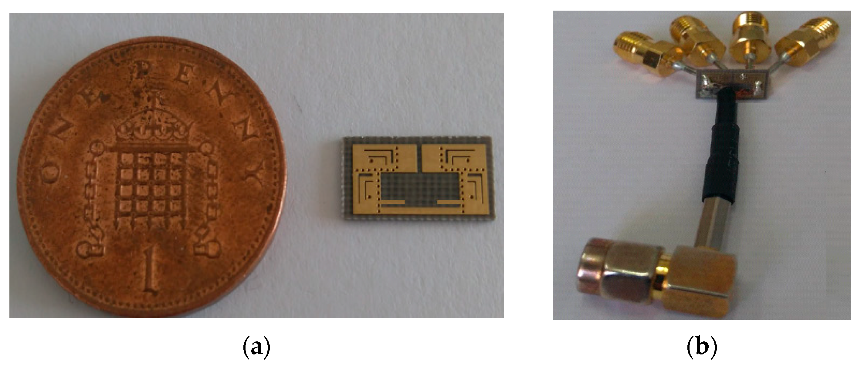
  • It is a multi-band, multi-application antenna that is integrated into a single-layer PCB with a quite small overall footprint area of only 6 × 10 mm2 (0.1λ0 × 0.18λ0), where λ0 represents the free space wavelength at 5.5 GHz.
  • For the first time, three distinct resonances with a high frequency ratio of approximately 23 are generated from a shared-aperture antenna that comprises integrated SIW sub-cavities. Furthermore, these sub-mode cavity antennas are used with the dual-mode composite to form sub-6 GHz Mw band antennas. This results in a very high reuse aperture utilization (RAU) efficiency of about 92%.
The paper is structured as follows: Section 2 introduces the design of the proposed multi-band shared antenna and provides details on the design considerations. The evolution process of the proposed SIW antennas as well as a parametric study are investigated in Section 3. The surface current and electric field distributions are demonstrated in Section 3 to support the novelty of the proposed design. In Section 4, the simulated results are supported by measured results for both the reflection and the radiation characteristics. Next, the proposed antenna is compared to existing antenna solutions in Section 5. Finally, a brief conclusion is given in Section 6.

2. The Proposed Design Configuration

Figure 2 displays the design of the proposed four-band shared-aperture antenna. The main circuit board is made of a single layer FRB5 substrate with a thickness of 0.508 mm and a dielectric constant of 2.5. The total footprint area is approximately 6 × 10 mm2. The proposed antenna is composed of four QMSIW antennas, shown in Figure 2a. Each QMSIW antenna is fed through a 50 Ohm coaxial connector, as shown in Figure 2b. Each QMSIW has its fundamental resonant mode frequency around 28 GHz, which is controlled by the open-end wall in each. In order to add two extra MMw frequency bands of operation, each QMSIW cavity is loaded by two L-shaped slots etched on its top surface (Slot 1 and Slot 2). These slots and other main components of the proposed antenna are labeled in Figure 2c. Slot 1 length controls the radiation around 38 GHz, while Slot 2 length contributes to the radiation around 0.13 THz. As can be clearly seen in Figure 2c, the four-QMSIW MIMO antennas are arranged orthogonally to achieve patterns and polarization diversities.
Finally, the proposed shared-aperture antenna is the result of deploying the structure reuse concept in the 5.5 GHz Mw frequency band. One additional Port (Port 5 in Figure 2a) is used for function structure reuse. For the purpose of enhancing and tuning radiation at 5.5 GHz two modifications are made to the entire proposed structure: (1) A metal strip (referred to as a stub in Figure 2c) connects the top surfaces of QMSIW pairs. (2) A small gap is created in the upper part between the top two pair cavities. Accordingly, the Port 5 antenna at 5.5 GHz is simply a small open-loop antenna, where all SIW structures exhibit conventional strips. Figure 2d shows the detailed dimensions of the proposed antenna structure.

3. Evolution Process and Parametric Study

This section details the progression of the proposed antenna’s design, with an emphasis on the surface current distribution for better understanding. Additionally, it examines the influence of crucial design parameters on the reflection coefficients’ frequency response.

3.1. Evolution Process

The design process of the proposed quad-band antenna begins with the design of the MMw antenna element. Thus, a full-mode SIW (FMSIW) cavity structure is designed to have resonant frequency of its fundamental mode (TE101) at 28 GHz. The general geometry of the FMSIW is shown in Figure 3a, in which all design parameters are derived using Equations (1)–(3) [24,27].
d s 0.5
W e q u = C f T E 101 2 ε r
W s i w = W e q u + d 2 0.95   s
where, d represents vias diameter, s represents the separation period between vias, f T E 101 is the resonant frequency of the fundamental mode inside the FMSIW cavity, W e q u represents the equivalent width of the traditional RWG, and W s i w represents the width of the SIW cavity wall (transverse spacing between the centers of the vais).
Based on the calculated design parameters, a 3D model of the FMSIW cavity antenna element is created using CST Microwave Studio. As shown in Figure 3a, a standard 50 Ohm microstrip excites the FMSIW cavity. The resulting electric field distribution at the resonant frequency (28 GHz) of the dominant mode (TE101) is shown in Figure 4a. A quarter of the entire FMSIW cavity is highlighted in both Figure 3 and Figure 4; it has a quarter cycle of the full mode at 28 GHz, as shown in the left QMSIW in Figure 4b. This QMSIW can be excited instead of the FMSIW, and at a much smaller size (miniaturized design). In addition to the dominant mode electric field distribution at 28 GHz, the electric field distributions at two higher order modes are presented in Figure 4 (TE102 and TE106 at 38 GHz and 0.13 THz). Their field distribution will help in determining the best locations for slot radiators at their frequencies. This is because they have weak electric field magnitudes at the open-edge walls of the sub-cavity (QMSIW) and are unable to efficiently radiate at 38 GHz and 0.13 THz. The REF1 antenna (shown in Figure 5) operates with a single mode of radiation at 28 GHz. This fact is clearly evident from the simulation results of the REF1 antenna, as depicted in Figure 6a.
Based on the electric field distribution at 38 GHz (see Figure 4), the REF2 antenna is developed by carving an inverted-L slot (Slot 1) on the top of the QMSIW, as depicted in Figure 5. The location and size of the slot are optimized to efficiently radiate the incident energy of the TE102 QMSIW mode at 38 GHz. A new radiated mode is presented at 38 GHz, as shown in Figure 6a.
In order to have tri-band operation, another inverted-L slot (Slot 2) is created as shown in REF3 in Figure 5, which releases the electromagnetic energy of the TE106 QMSIW mode into the free space at 0.13 THz. Figure 6b presents the simulated results of the reflection parameters at 0.13 THz. Accordingly, the proposed single-element dual-slot QMSIW antenna supports three frequency bands: 28 GHz, 38 GHz, and 0.13 THz, respectively.
In order to design a four-element MIMO antenna for the three MMw bands, four QMSIW antennas (REF3) are arranged in a way that permits both polarization and space diversities. This can be simply seen in the REF4 antenna in Figure 5. Two pairs of QMSIWs are connected through a new feeding port (Port 5). Port 5 is used to activate structure-reuse by exciting a half-wavelength dipole-like Mw antenna, which is made from the four QMSIW antenna elements. However, the dipole resonates at around 6.4 GHz, and it encounters a mismatching issue, as indicated by the REF 4 curve in Figure 7. To address this issue and to tune the resonant frequency toward 5.5 GHz, REF5 is evolved by adding extra inductance through a balun strip that connects the two arms of the structure (REF5 is shown in Figure 5). This decreases the operating frequency of Port 5 down to 4.8 GHz but with a very low matching efficiency, as shown by the blue curve in Figure 7.
Finally, the Port 5 Mw antenna (the proposed antenna in Figure 5) is optimized by tuning the gap width between the top cavity pair. Its resonant frequency was shifted to 5.5 GHz, as shown in Figure 7, where a 200 MHz 10-dB impedance bandwidth is covered around 5.5 GHz. On the other hand, the MMw MIMO antenna, represented by the four-element MIMO QMSIW antenna, successfully covers the three targeted bands: 28 GHz, 38 GHz, and 0.13 THz, as shown in the reflection scattering parameters in Figure 8a,b. Both figures (Figure 8a, Figure 8b) also show that the achieved isolation levels are higher than 18 dB, 25 dB, and 22 dB for the 28 GHz, 38 GHz, and 0.13 THz, respectively.

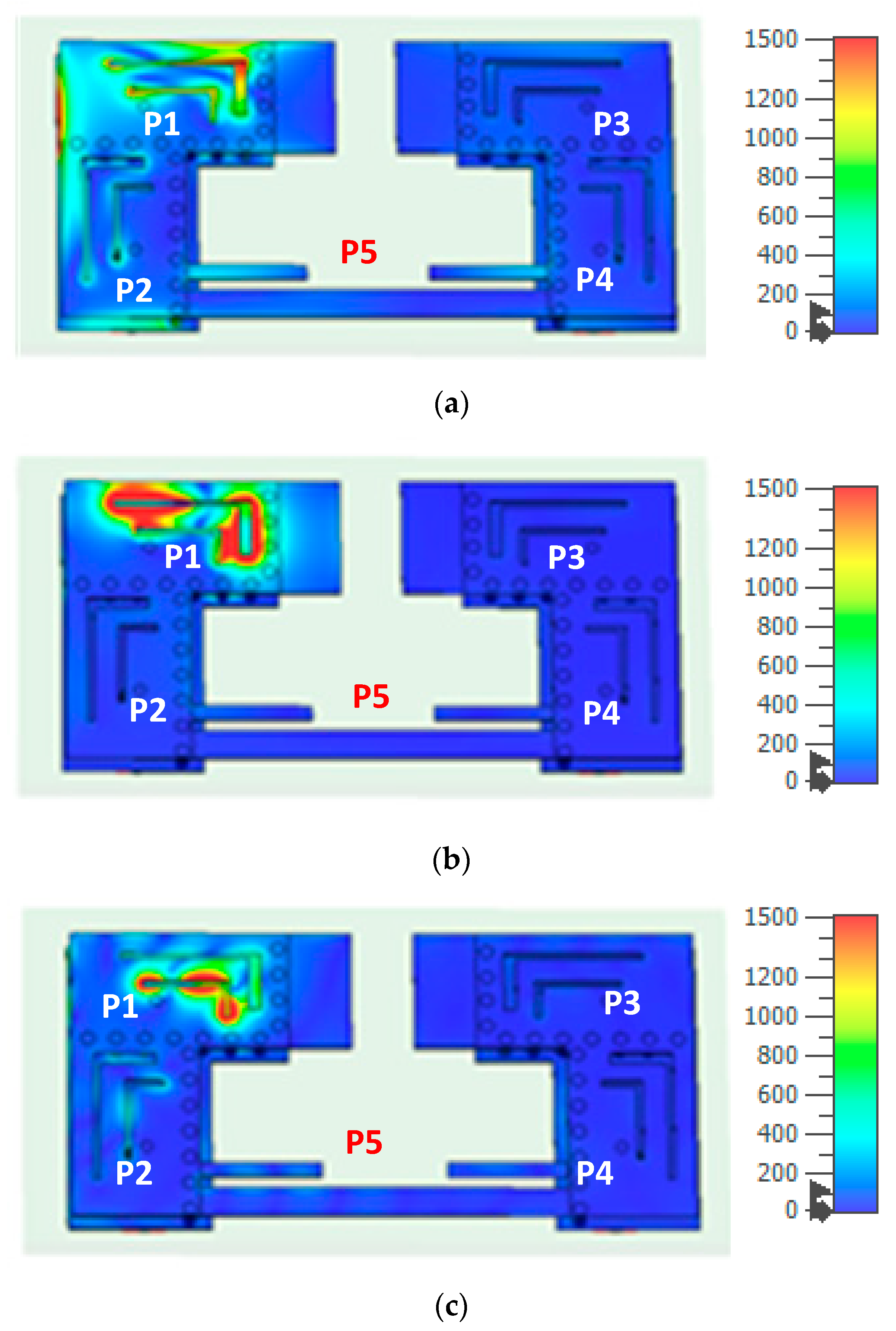
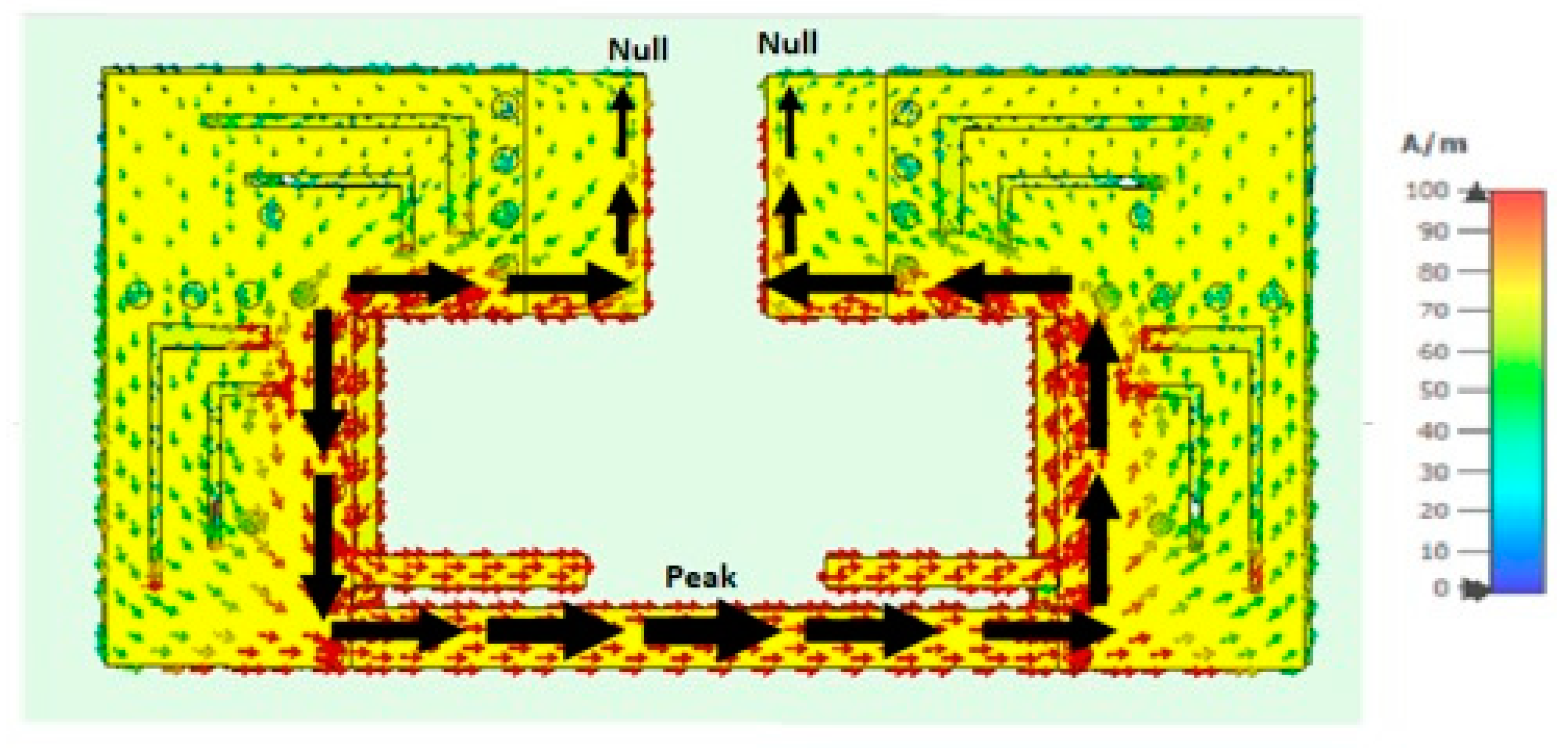
3.2. Surface Current Distributions

The surface current distributions of the proposed shared-aperture antenna at four critical MMw frequencies are displayed in Figure 9. Figure 9a depicts the main radiator at 28 GHz as the open edge of the QMSIW cavity; this can be noticed from the strong surface current on the open edges of the Port 1 antenna (the top right corner of the whole structure). Slot 1 and Slot 2 interrupt the current paths on the top of the QMSIW cavity to support the operation at 38 GHz and 0.13 THz, respectively. Figure 9b displays a full-wavelength current mode on Slot 1 at 38 GHz; two half-wave current cycles are around the contour of the slot. Figure 9c shows a 2λ current mode on Slot 2 at 0.13 THz; four half-wave current cycles are around the contour of the slot.
Additionally, Figure 9 provides extra physical insight regarding the isolation level between antenna ports. It can be seen that as the Port 1 antenna is excited while others are terminated with a 50 Ohms matched load, a very low mutual coupling current is induced in the other antenna ports (Port 2, Port 3, Port 4, and Port 5). This can be seen at the three operating MMw bands (28 GHz in Figure 9a, 38 GHz in Figure 9b, and 0.13 THz in Figure 9c). This low level of coupling is due to two reasons: (1) the presence of metal vias between adjacent QMSIW cavities prevents the current from flowing between adjacent elements, and (2) polarization diversity is employed between adjacent antenna elements, which are arranged orthogonally to each other.
The proposed antenna structure’s reliability has been verified through the extraction of a simulated vector surface current distribution at 5.5 GHz from a 3D simulation model in CST Microwave Studio, as depicted in Figure 10. The shared-aperture antenna (the entire SIW structure) exhibits a behavior similar to a conventional strip antenna when it is excited at low resonant frequencies (Mw frequencies). The Port 5 antenna has an open-loop structure that resonates at its half-wave length resonant current mode, as shown in Figure 10. Two current nulls are at the open edges and one peaks at the middle of the open loop. Furthermore, the excited current mode is concentrated near the inner contour of the open loop, this prevents other MMw ports (Port 1, Port 2, Port 3, and Port 4) from being significantly impacted by the mutual coupling. As a result, no external isolation circuits are required at the 5.5 GHz, 28 GHz, 38 GHz, and 0.13 THz frequencies.

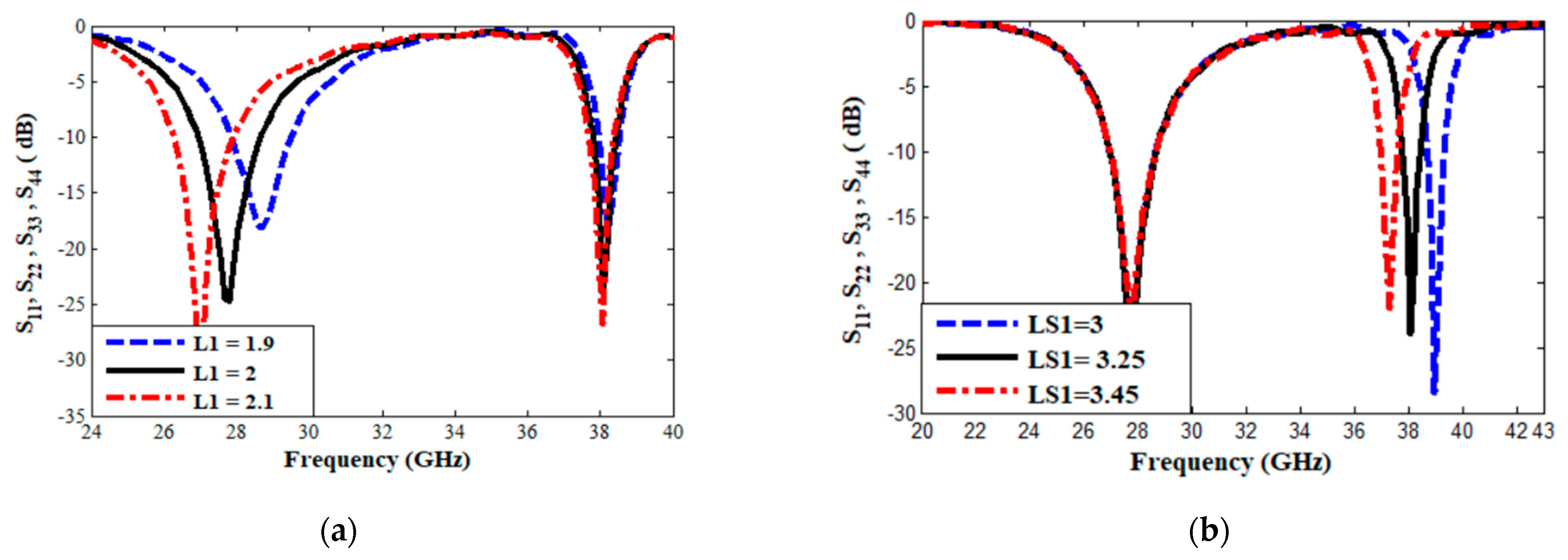
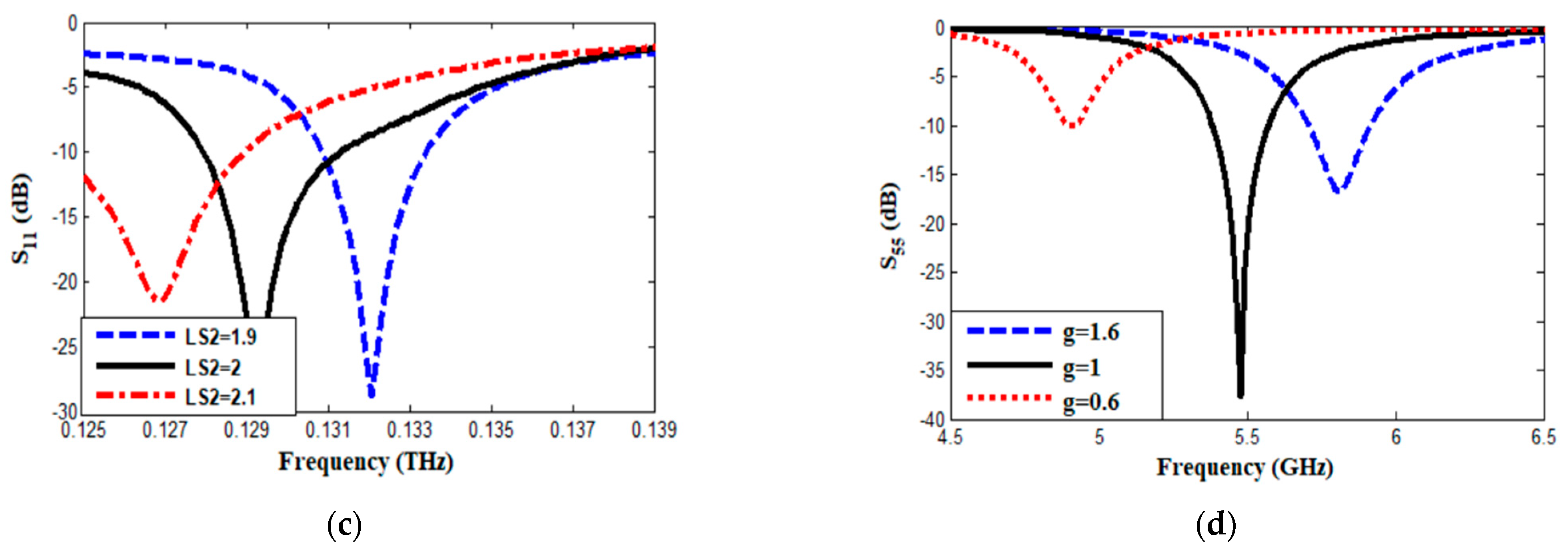
3.3. Parametric Study

For further clarification of the results and of the operation of the proposed antenna, the impact of key design parameters on the scattering parameters was studied using CST Microwave Studio. Figure 11 shows the results of four separate studies on four design parameters. It is important to note that each parameter was varied individually while the others were kept constant. Figure 11a demonstrates that the resonant frequency of the TE101 mode at 28 GHz can be adjusted by changing length L1 of the QMSIW cavity. The resonant frequency decreases as L1 increases. Figure 11b,c reveals that the resonant frequencies at 38 GHz and 0.13 THz are linked to the overall lengths of Slot 1 (LS1) and Slot 2 (LS2), respectively. An interesting finding is that the resonant frequency of the QMSIW cavity at 28 GHz does not change during the tuning of the two slots, which highlights the effectiveness of the proposed slot topology, as the slots are designed in a way that does not impact the fundamental cavity mode at 28 GHz. Finally, the total length of the open loop can be changed by altering either the gap width (g) or the stubs’ length (Lt). For simplicity, only the effect of gap width is shown in Figure 11d. This confirms that the main radiator at 5.5 GHz is the resulting open-loop antenna.

4. Simulated and Measured Results

To verify the simulated results, an antenna prototype was constructed and tested using an Anritsu MS46322B vector network analyzer (VNA). Figure 12a,b shows photos of the prototype before and after assembly, respectively, with the latter featuring CAB.058 SMA(F)Jack SMA connectors. It is noteworthy that the simulation results at 5.5 GHz, 28 GHz, and 38 GHz were confirmed by the experimental results. The results at 0.13 GHz were validated through another numerical solver, the Finite Element Method in Ansys HFSS 3D full wave simulation, as the VNA maximum frequency is 50 GHz.

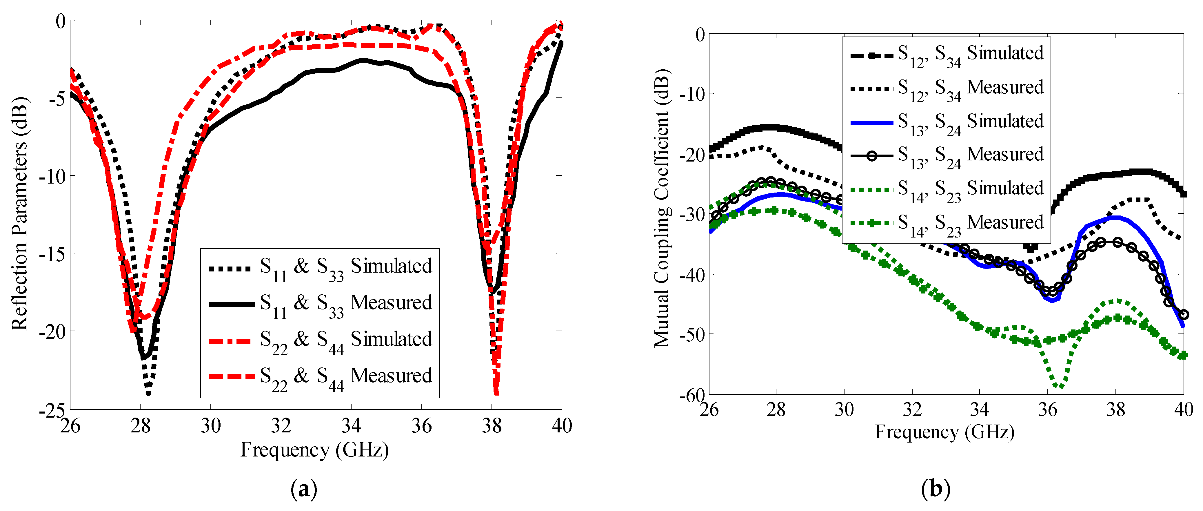
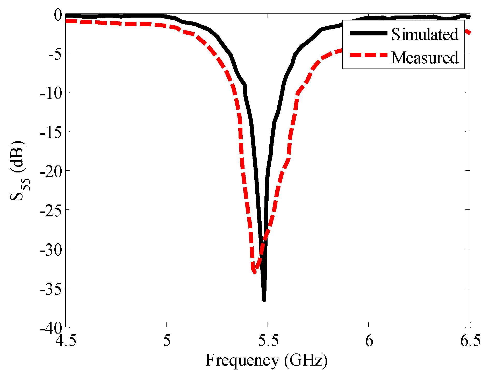
4.1. Scattering Parmeters

Figure 13a shows the simulated and measured reflection coefficients at ports 1, 2, 3, and 4 for the 28 GHz and 38 GHz bands, while Figure 13b shows the transmission coefficients (mutual coupling) at all ports for the same bands. Good agreement is seen between the simulated and measured results for the four-element QMSIW antenna used for MIMO operation. The measured 10 dB return loss bandwidth at 28 GHz is approximately 2 GHz (26.5–28.5 GHz), and 1 GHz at 38 GHz (37.5–38.5 GHz). Figure 13b shows the lowest isolation levels among antenna elements, which are excellent at around 25 dB due to the use of the orthogonal arrangement of elements as well as the shorting vias between elements.
Figure 14 shows the scattering parameter results of a four-element QMSIW antenna at 0.13 THz obtained using two different numerical methods: the finite difference time domain (FDTD) method using CST Microwave Studio and the finite element (FEM) method using Ansys HFSS. The results in Figure 14a are in good agreement, and the achieved impedance bandwidth of 10 dB is about 3 GHz (0.128–0.131 THz). Figure 14b shows that the isolation levels are above 20 dB for the 0.13 THz band without the use of any additional decoupling circuits. For brevity, only the strongest levels of mutual coupling parameters are presented in Figure 14b.
Finally, Figure 15 shows the measured and simulated reflection parameters on the Port 5 antenna at 5.5 GHz. The measured reflection parameter has a wider bandwidth, which may be due to additional lengths of the SMA connectors that were not included during the calibration process. The simulation result shows a 10 dB impedance bandwidth of about 200 MHz (5.4–5.6 GHz), sufficient for 5.5 GHz WiFi applications. It is worth mentioning that the level of mutual coupling between the MMw four-port antenna and the Mw open-loop antenna (Port 5) is below −40 dB, but these results are not presented for brevity. As a result, the isolation between the five antennas is high enough to allow them to radiate independently and simultaneously. Therefore, it can be concluded that this proposed antenna is potentially valid to work as a shared-aperture reuse-structure antenna based on the QMSIW cavity.

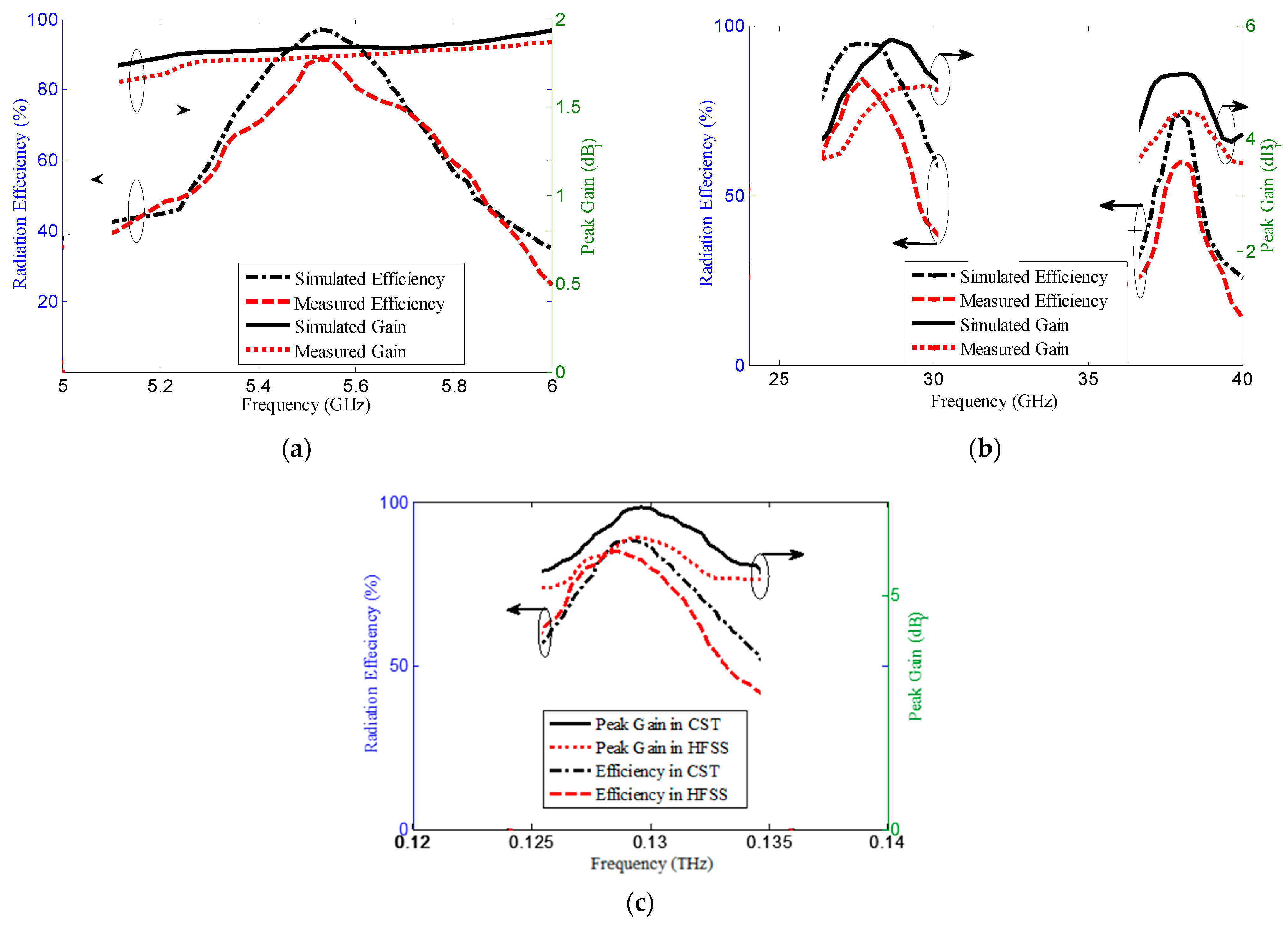
4.2. Total Radiation Effciency and Gain

The measured results have confirmed the validity of the simulated total radiation efficiency and peak gain at both the Mw and MMw bands. Figure 16a shows the results for the sub-6 GHz Mw frequency band, where a small discrepancy between the simulated and measured results can be observed, but the proposed open-loop antenna (Port 5) has a total radiation efficiency between 80–85% and a corresponding peak gain of about 1.8 dBi over the frequency band. Figure 16b displays the results for the MMw frequency bands at 28 GHz and 38 GHz, where only the results for the Port 1 antenna are presented, since all ports have similar performance. The difference between the simulated and measured results is larger and is caused by the extended-length connectors. However, both the simulated and measured results show similar trends. The MIMO antenna elements have a measured total efficiency of over 73% at 28 GHz and over 62% at 38 GHz with a peak gain of 4–4.5 dBi and 4.3–4.5 dBi at the 28 GHz and 38 GHz frequency bands, respectively. Using proper connectors to excite the MMw antenna could bring the measured results to the same level as the simulated ones. The results at 0.13 THz were carefully calculated using two reliable full-wave simulators, FDTD in CST and FEM in HFSS. Figure 16c shows that both techniques produced similar results, with the total efficiency of antenna ports 1 and 3 ranging from 78–85% and 72–85%, respectively, the peak gain of FDTD results ranging from 6.5 to 6.6 dBi, and the FEM results varying from 6.35 dBi to 6.42 dBi. This demonstrates the reliability of the results at 0.13 THz.

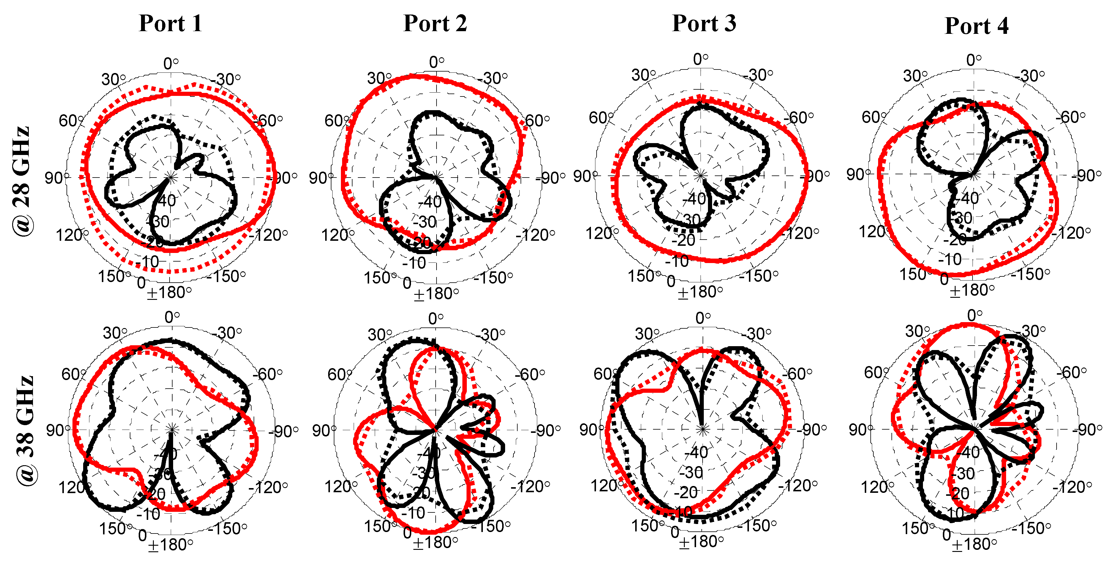
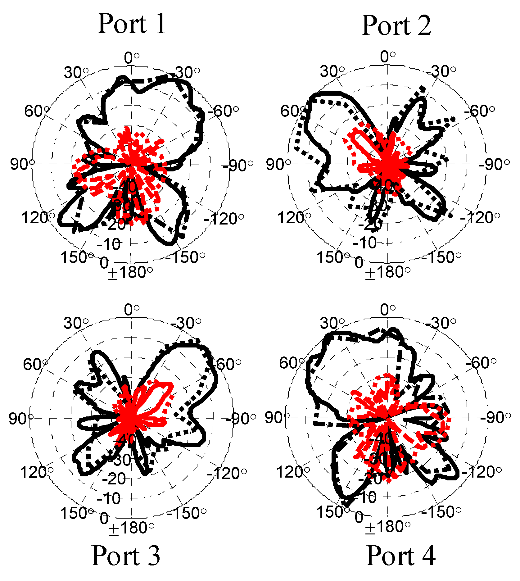
4.3. Far-Field Radiation Patterns

Figure 17 displays the compared 2D normalized far-field radiation patterns of the Port 5 antenna (open-loop antenna) at 5.5 GHz, both simulated and measured. Although there are slight deviations in the measured results from the simulations, which are mostly due to the presence of large feeding connectors, the deviations are within the acceptable limits. Both patterns exhibit directional characteristics similar to those of an x-directed dipole antenna.
Figure 18 displays the results of the four-element MIMO antenna’s XY pattern at frequencies of 28 GHz and 38 GHz, both simulated and measured. The results on other planes are not included for brevity. It is evident that some of the measured results deviate from the simulations, which could be due to the use of large connectors or variations in the position of the soldered connectors. Nonetheless, the co-polarized patterns at 28 GHz exhibit an omnidirectional shape in a complementary manner, indicating that the primary radiation structures at 28 GHz are the open-edge QMSIW cavity antennas. Meanwhile, the co-polarized patterns at 38 GHz are directional, confirming that the main radiators are the larger slots in each QMSIW cavity.
In Figure 19, the results of the simulated XY radiation pattern at 0.13 THz are displayed. To guarantee the accuracy of the results at this frequency, two full-wave simulation tools, CST Microwave Studio and Ansys HFSS, were used, as the maximum frequency limit of the available VNA is 50 GHz. The figure presents the directional patterns in a complementary manner, and the cross-polarized patterns are shown to be almost less than −25 dB.

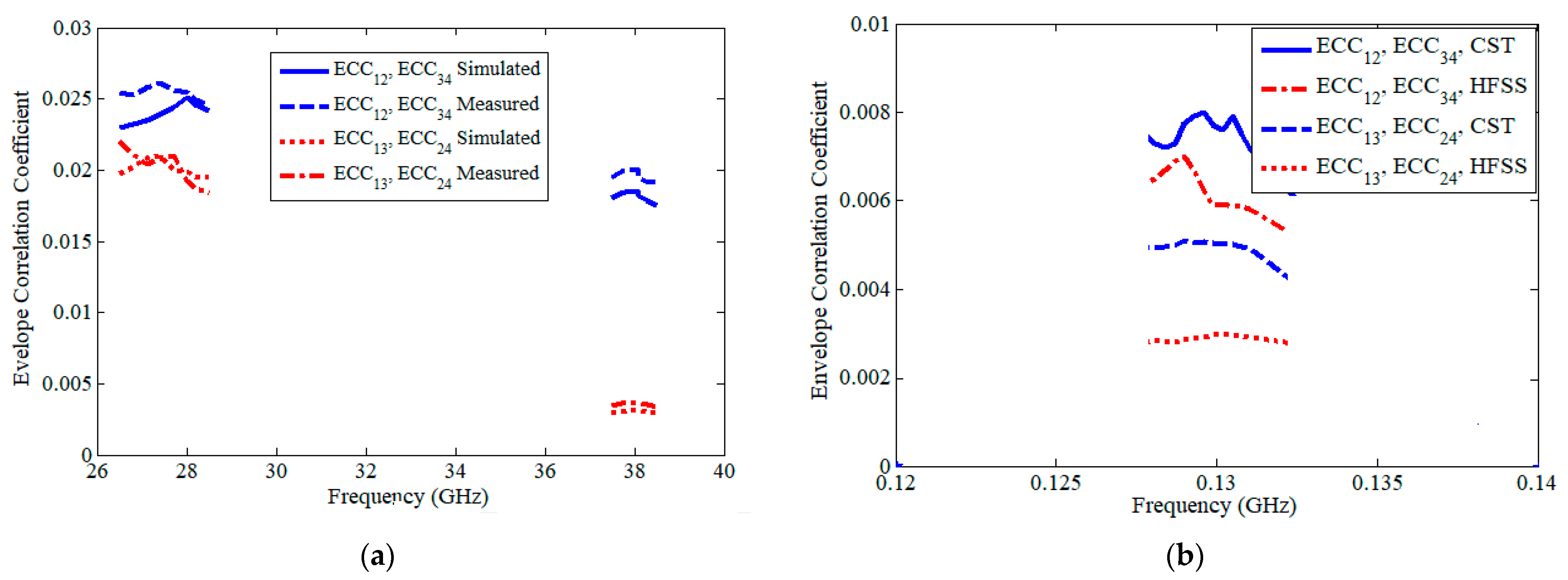
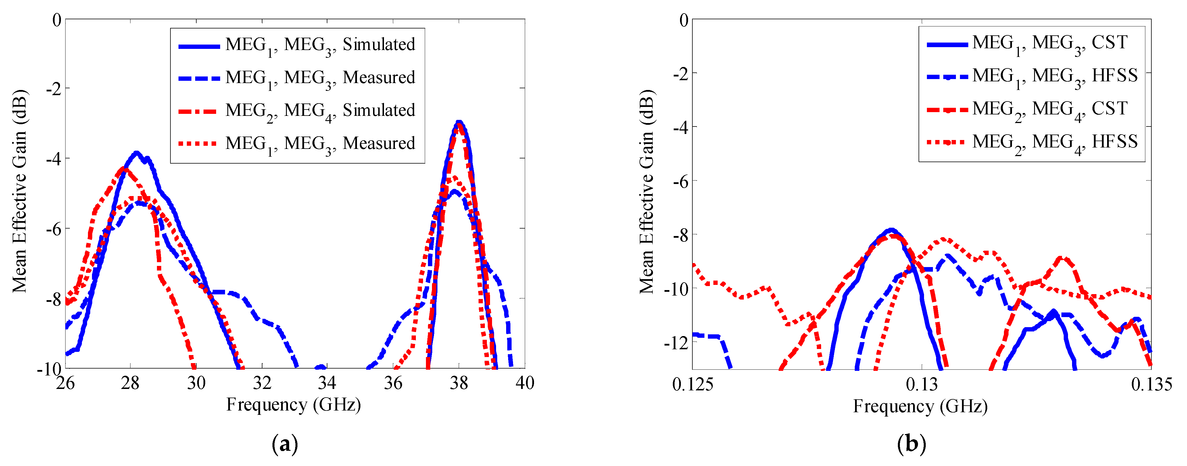
4.4. MIMO Performance Parameters

In order to investigate the robustness of the proposed antenna’s MIMO operation, three bands are explored: 26.6–28.5 GHz, 37.5–38.5 GHz, and 0.128–0.131 THz. Several MIMO performance parameters can be investigated, such as the envelope correlation coefficient (ECC) [42,43,44], mean effective gain (MEG) and power balance condition [44,45], diversity gain (DG) [46], and channel capacity loss (CCL) [47]. A robust MIMO antenna system should satisfy two important conditions, which are linked to both ECC and the branch power ratio condition in terms of MEG. These two conditions are described as follows:
E C C 0.5
k = | M E G i M E G j | 0 d B
where k is the branch power ratio, MEGi is the mean effective gain of ith antenna element, and MEGj is the mean effective gain of the jth antenna element. The calculation of MEG can be performed using (6) [46].
M E G i = 0.5 [ 1 ( j = 1 4 | S i j | ) ]
Ideal MIMO antenna systems should have equal power levels among different branches (k = 0 dB), but practically, MIMO antennas can have excellent MIMO and diversity performance if the branch ratio is less than 3 dB (k < 3 dB) [45].
For the purpose of conciseness, this paper solely focuses on analyzing the ECC and MEG aspects, since they provide a distinct assessment of the strength and stability of the suggested MIMO antenna system.
The simulated and measured results of ECC for the proposed four-element QMSIW antenna were calculated based on far-field patterns at 28 GHz, 38 GHz, and 0.13 THz. Figure 20a shows both the measured and simulated results at the 28 GHz and 38 GHz frequency bands, while co-simulation results are presented in Figure 20b for the sub-THz frequency band. The results for each figure are in good agreement, and all are well below the critical limit of ECC, as described in (4) [42,43,44]. Thus, the ECC results assured excellent MIMO and diversity performance.
Figure 21 shows both the MEG and the branch power results over the operational frequency bands. The results in Figure 21a,b validate each other and show that the values of MEG for each antenna element are very close, ensuring a very low branch ratio over the frequency band of interest. This is clearly evident in Figure 21c,d, as the branch power ratio values are below 3 dB. Thus, as both diversity conditions are satisfied, the proposed antenna represents a very efficient MIMO antenna solution over the three frequency bands (26.5–28.5 GHz, 37.5–38.5 GHz, and 0.128–0.131 THz).

5. State-of-the-Art Comparison

This section highlights the most prominent contributions of the proposed antenna design in comparison to the current state-of-the-art of the multi-band shared-aperture MIMO antenna. Table 1 summarizes the comparison as follows:
  • The proposed antenna is designed based on a new hybrid design technique; it is based on a dual-mode composite antenna and higher-order modes of sub-mode-SIW-cavities for the first time. This is different from current techniques of shared-aperture antennas in the open literature, which are designed based on the dual-mode composite and higher-order modes of full-mode cavity antennas [30,31,32,33,34,35], while self-multiplexing antennas are based on sub-mode cavity antennas alone, without the dual-mode concept [20,21,22,23,24,25,26,27,28,29].
  • In terms of frequency ratio, most current design techniques have low frequency ratios, as they are only able to operate in a few close frequencies in either Mw [25,26,31,32,34] or MMw [21,24,30,33], or both [37,38,40]. The proposed design has a high frequency ratio (about 23), as it operates in Mw, MMw, and sub-THz frequency applications. Although the proposed design in [37] has a higher frequency ratio than this work, the current work has a very small footprint area ( 0.018 λ 0 2 ) compared to [37].
  • Regarding the electrical size, and for fair comparison with reported works, the calculation of footprint area was made at the longest wavelength of each reported work. Consequently, the proposed antenna has the lowest footprint area compared to all previous works in the table. The footprint area is calculated based on the electrical lengths; it is about 0.018 λ 0 2 , where λ0 represents the free space wavelength at 5.5 GHz frequency.
  • The proposed design represents the first shared-aperture design with four-port MIMO operation at MMw and sub-THz frequencies.
  • In terms of the reuse aperture utilization (RAU) efficiency as described in (4), the presented design technique is very efficient, as it has a large RAU (about 92%).
    R A U = S r S
    where, S is the occupied footprint area of the larger antenna (the open-loop antenna, which is fed by Port 5), while Sr is the occupied area of the smaller antennas, the QMSIW antennas.
Table 1. Comparison of the proposed with other shared-aperture antenna designs.
RefDesign TechniqueOperation Bands
No. of Freq (GHz/THz)
MIMORAU [%]RFArea [ λ 0 2 ]
Sub-THzMMwMw
[32]HOM, FMSIWNoNoYes, 3.2/3.8No671.180.71
[30]HOM, FMSIWNoYes, 28/38NoNo621.350.2
[31]HOM, FMSIWNoNoYes, 2.6/5.9No32.260.104
[33]HOM, FMSIWNoYes, 28/33/38NoNo23.61.357.22
[34]HOM, FMSIWNoNoYes, 9.84/10.2No3.71.030.348
[35]HOM, FMSIWNoNoYes, 9.4/16No14.61.70.164
[37]DMC, FMSIWNoYes, 60Yes, 2.4/5.4Yes, 2-port92250.464
[38]DMC, FMSIWNoYes, 28/38Yes, 2.3/2.4/2.5/3.5/5NoN.A160.563
[40]DMC, FMSIWNoYes, 60Yes, 3.5No72170.126
[21]SMSIWNoYes, 28/38NoNo901.354.622
[25]Ant.diplexer, SMSIWNoNoYes, 6.44/7.09No381.10.476
[26]Ant.diplexer, SMSIWNoNoYes, 3.4/3.8Yes891.110.16
[27]Ant.triplexer, SMSIWNoNoYes, 5.57/7.17/7.65No781.370.435
[28]Ant.triplexer, SMSIWNoNoYes, 6.53/7.65/9.09No621.390.42
[24]Ant.quadrplexer, SMSIWNoYes, 28/30Yes, 4.8/5.4NoN.A6.250.260
[29]Ant.quadrplexer, SMSIWNoNoYes, 2.45/3.5/4.9/5.4No692.20.053
[This]HOM, DMC, and SMSIWYes, 0.13Yes, 28/38Yes, 5.5Yes, 4-port92230.018
HOM: Higher Order Modes, FMSIW: Full-mode SIW, SMSIW: Sub-mode SIW, DMC: Dual-mode Composite.

6. Conclusions

In conclusion, this research presents a novel design for an ultra-compact shared-aperture antenna (footprint area equals 0.018 λ 0 2 ) that can operate in the 5G MMw bands, the 6G sub-THz band, and the wireless fidelity microwave band. By incorporating four quarter-mode substrate integrated waveguide (QMSIW) cavity resonators, a close-spaced tri-band 4 × 4 multi-input, multi-output (MIMO) antenna is achieved for high-frequency applications. The proposed antenna demonstrates good characteristics regarding scattering parameters, antenna gains, efficiency, radiation pattern, envelope correlation coefficient, and mean effective gain power ratio through simulations, measurement, and co-simulation. The proposed design offers excellent performance and shows promising potential for practical applications in future wireless communication systems. The compact footprint of the antenna makes it very promising for integration into planar circuits in mobile and IoT devices. Thus, continuous research shall be conducted to integrate this new design into smartphone devices.

Author Contributions

Conceptualization, S.S.A. and A.T.A.; methodology, S.S.A. and A.T.A.; software, S.S.A., A.T.A. and E.A.; validation, S.S.A. and A.T.A.; formal analysis, A.M.A.; investigation, S.S.A. and A.M.A.; resources, S.S.A. and E.A.; data curation, S.S.A., A.T.A. and L.A.-T.; writing—original draft preparation, S.S.A., A.T.A., A.M.A., E.A., L.A.-T. and J.Y.; writing—review and editing, S.S.A., A.T.A., A.M.A., E.A., L.A.-T. and J.Y.; visualization, S.S.A., A.T.A. and A.M.A.; supervision, S.S.A.; project administration, S.S.A.; funding acquisition, S.S.A., A.T.A., A.M.A., E.A., L.A.-T. and J.Y. All authors have read and agreed to the published version of the manuscript.

Funding

This research received no external funding.

Institutional Review Board Statement

Not applicable.

Informed Consent Statement

Not applicable.

Data Availability Statement

Not applicable.

Conflicts of Interest

The authors declare no conflict of interest.

References

  1. Zhang, Z.; Xiao, Y.; Ma, Z.; Xiao, M.; Ding, Z.; Lei, X.; Karagiannidis, G.K.; Fan, P. 6G Wireless Networks: Vision, Requirements, Architecture, and Key Technologies. IEEE Veh. Technol. Mag. 2019, 14, 28–41. [Google Scholar] [CrossRef]
  2. Rappaport, T.S.; Xing, Y.; Kanhere, O.; Ju, S.; Madanayake, A.; Mandal, S.; Alkhateeb, A.; Trichopoulos, G.C. Wireless Communications and Applications above 100 GHz: Opportunities and Challenges for 6G and beyond. IEEE Access 2019, 7, 78729–78757. [Google Scholar] [CrossRef]
  3. Tong, W.; Zhu, P. (Eds.) 6G: The Next Horizon: From Connected People and Things to Connected Intelligence, 2021 ed.; Cambridge University Press: Cambridge, UK, 2021. [Google Scholar]
  4. Paoloni, C. Sub-THz Wireless Transport Layer for Ubiquitous High Data Rate. IEEE Commun. Mag. 2021, 59, 102–107. [Google Scholar] [CrossRef]
  5. Petrov, V.; Kurner, T.; Hosako, I. IEEE 802.15.3d: First Standardization Efforts for Sub-Terahertz Band Communications toward 6G. IEEE Commun. Mag. 2020, 58, 28–33. [Google Scholar] [CrossRef]
  6. Saraereh, O.A.; Al-Tarawneh, L.; Ali, A.; Al Hadidi, A.M. Design and Analysis of a Novel Antenna for THz Wireless Communication. Intell. Autom. Soft Comput. 2022, 31, 607–619. [Google Scholar] [CrossRef]
  7. 5G-ACIA. Position Paper: Our View on the Evolution of 5G toward 6G; 5G-ACIA: Frankfurt, Germany, 2021. [Google Scholar]
  8. Naqvi, S.I.; Hussain, N.; Iqbal, A.; Rahman, M.; Forsat, M.; Mirjavadi, S.S.; Amin, Y. Integrated LTE and Millimeter-Wave 5G MIMO Antenna System for 4G/5G Wireless Terminals. Sensors 2020, 20, 3926. [Google Scholar] [CrossRef]
  9. Hussain, R.; Alreshaid, A.T.; Podilchak, S.K.; Sharawi, M.S. Compact 4G MIMO antenna integrated with a 5G array for current and future mobile handsets. IET Microw. Antennas Propag. 2017, 11, 271–279. [Google Scholar] [CrossRef]
  10. Ikram, M.; Al Abbas, E.; Nguyen-Trong, N.; Sayidmarie, K.H.; Abbosh, A. Integrated Frequency-Reconfigurable Slot Antenna and Connected Slot Antenna Array for 4G and 5G Mobile Handsets. IEEE Trans. Antennas Propag. 2019, 67, 7225–7233. [Google Scholar] [CrossRef]
  11. Al Abbas, E.; Ikram, M.; Mobashsher, A.T.; Abbosh, A. MIMO Antenna System for Multi-Band Millimeter-Wave 5G and Wideband 4G Mobile Communications. IEEE Access 2019, 7, 181916–181923. [Google Scholar] [CrossRef]
  12. Wang, D.; Chan, C.H. Multiband Antenna for WiFi and WiGig Communications. IEEE Antennas Wirel. Propag. Lett. 2015, 15, 309–312. [Google Scholar] [CrossRef]
  13. Liu, D.Q.; Zhang, M.; Luo, H.J.; Wen, H.L.; Wang, J. Dual-Band Platform-Free PIFA for 5G MIMO Application of Mobile Devices. IEEE Trans. Antennas Propag. 2018, 66, 6328–6333. [Google Scholar] [CrossRef]
  14. Deng, J.; Li, J.; Zhao, L.; Guo, L. A Dual-Band Inverted-F MIMO Antenna with Enhanced Isolation for WLAN Applications. IEEE Antennas Wirel. Propag. Lett. 2017, 16, 2270–2273. [Google Scholar] [CrossRef]
  15. Isaac, A.A.; Al-Rizzo, H.M.; Hammoodi, A.I.; Khaleel, H.R. Isolation enhancement of two planar monopole antennas for MIMO wireless applications. In Proceedings of the IEEE International Symposium on Antennas and Propagation (APS), Vancouver, BC, Canada, 19–24 July 2015; pp. 380–381. [Google Scholar]
  16. Alja’Afreh, S.; Huang, Y.; Xing, L. A compact, wideband and low profile planar inverted-L antenna. In Proceedings of the 8th European Conference on Antennas and Propagation (EuCAP 2014), The Hague, The Netherlands, 6–11 April 2014; pp. 3283–3286. [Google Scholar] [CrossRef]
  17. Alja’Afreh, S. An L-Shaped Antenna with a Triple-Broadband Operation for Digital UHF TV Reception and Sub-7 GHz 5G Applications. Int. J. Commun. Antenna Propag. (IRECAP) 2022, 12, 404. [Google Scholar] [CrossRef]
  18. Saleh, C.M.; Almajali, E.; Jarndal, A.; Yousaf, J.; Alja’Afreh, S.S.; Amaya, R.E. Wideband 5G Antenna Gain Enhancement Using a Compact Single-Layer Millimeter Wave Metamaterial Lens. IEEE Access 2023, 11, 14928–14942. [Google Scholar] [CrossRef]
  19. Deckmyn, T.; Agneessens, S.; Reniers, A.C.F.; Smolders, A.B.; Cauwe, M.; Ginste, D.V.; Rogier, H. A Novel 60 GHz Wideband Coupled Half-Mode/Quarter-Mode Substrate Integrated Waveguide Antenna. IEEE Trans. Antennas Propag. 2017, 65, 6915–6926. [Google Scholar] [CrossRef]
  20. Elobied, A.A.; Yang, X.-X.; Xie, N.; Gao, S. Dual-Band 2 × 2 MIMO Antenna with Compact Size and High Isolation Based on Half-Mode SIW. Int. J. Antennas Propag. 2020, 2020, 2965767. [Google Scholar] [CrossRef]
  21. Sun, Y.-X.; Wu, D.; Fang, X.S.; Yang, N. Compact Quarter-Mode Substrate-Integrated Waveguide Dual-Frequency Millimeter-Wave Antenna Array for 5G Applications. IEEE Antennas Wirel. Propag. Lett. 2020, 19, 1405–1409. [Google Scholar] [CrossRef]
  22. Niu, B.J.; Tan, J.H. Compact SIW cavity MIMO antenna with enhanced bandwidth and high isolation. Electron. Lett. 2019, 55, 631–632. [Google Scholar] [CrossRef]
  23. Singh, A.K. Paras compact self-quadruplexing antenna based on SIW cavity-backed with enhanced isolation. Prog. Electromagn. Res. C 2021, 110, 243–252. [Google Scholar] [CrossRef]
  24. Naseri, H.H.; Pour Mohammadi, P.; Iqbal, V.; Kishk, A.A.; Denidni, T.A. SIW-Based Self-Quadruplexing Antenna for Microwave and mm-Wave Frequencies. IEEE Antennas Wirel. Propag. Lett. 2022, 21, 1481–1486. [Google Scholar] [CrossRef]
  25. Kumar, A.; Chaturvedi, D.; Raghavan, S. Design of a self-diplexing antenna using SIW technique with high isolation. AEU Int. J. Electron. Commun. 2018, 94, 386–391. [Google Scholar] [CrossRef]
  26. Niu, B.J.; Cao, Y.J. Dual-functional QM SIW cavity integrating two-element MIMO antenna and second-order bandpass filter. Int. J. RF Microw. Comput. Aided Eng. 2020, 30, e22355. [Google Scholar] [CrossRef]
  27. Kumar, A.; Chaturvedi, D.; Raghavan, S. Low-profile substrate integrated waveguide (SIW) cavity-backed self-triplexed slot antenna. Int. J. RF Microw. Comput. Aided Eng. 2019, 29, e21606. [Google Scholar] [CrossRef]
  28. Kumar, A.; Raghavan, S. A self-triplexing SIW cavity-backed slot antenna. IEEE Antennas Wirel. Propag. Lett. 2018, 17, 772–775. [Google Scholar] [CrossRef]
  29. Iqbal, A.; Tiang, J.J.; Wong, S.K.; Wong, S.W.; Mallat, N.K. SIW Cavity-Backed Self-Quadruplexing Antenna for Compact RF Front Ends. IEEE Antennas Wirel. Propag. Lett. 2021, 20, 562–566. [Google Scholar] [CrossRef]
  30. Deckmyn, T.; Cauwe, M.; Ginste, D.V.; Rogier, H.; Agneessens, S. Dual-Band (28,38) GHz Coupled Quarter-Mode Substrate-Integrated Waveguide Antenna Array for Next-Generation Wireless Systems. IEEE Trans. Antennas Propag. 2019, 67, 2405–2412. [Google Scholar] [CrossRef]
  31. Yue, T.; Werner, D.H. A compact dual-band antenna based on SIW technology. In Proceedings of the 2018 IEEE International Symposium on Antennas and Propagation & USNC/URSI National Radio Science Meeting, Boston, MA, USA, 8–13 July 2018; pp. 779–780. [Google Scholar]
  32. Niu, B.J.; Tan, J.H.; He, C.L. SIW cavity-backed dual-band antenna with good stopband characteristics. Electron. Lett. 2018, 54, 1259–1260. [Google Scholar] [CrossRef]
  33. Chen, H.; Shao, Y.; Zhang, Y.; Zhang, C.; Zhang, Z. A Millimeter-Wave Triple-Band SIW Antenna with Dual-Sense Circular Polarization. IEEE Trans. Antennas Propag. 2020, 68, 8162–8167. [Google Scholar] [CrossRef]
  34. Luo, G.Q.; Hu, Z.F.; Li, W.J.; Zhang, X.H.; Sun, L.L.; Zheng, J.F. Bandwidth-Enhanced Low-Profile Cavity-Backed Slot Antenna by Using Hybrid SIW Cavity Modes. IEEE Trans. Antennas Propag. 2012, 60, 1698–1704. [Google Scholar] [CrossRef]
  35. Zhang, T.; Hong, W.; Zhang, Y.; Wu, K. Design and Analysis of SIW Cavity Backed Dual-Band Antennas with a Dual-Mode Triangular-Ring Slot. IEEE Trans. Antennas Propag. 2014, 62, 5007–5016. [Google Scholar] [CrossRef]
  36. Altakhaineh, A.T.; Alja’Afreh, S.S. A Dual-Frequency Single-Slot Substrate Integrated Waveguide Antenna for 5G Millimeter Applications. In Proceedings of the International Conference on Emerging Trends in Computing and Engineering Applications (ETCEA), Karak, Jordan, 23–24 November 2022; pp. 1–3. [Google Scholar] [CrossRef]
  37. Ding, Y.R.; Cheng, Y.J. A Tri-Band Shared-Aperture Antenna for Wi-Fi MIMO and Beam-Scanning Wi-Gig Applications. In Proceedings of the 2019 IEEE International Symposium on Antennas and Propagation and USNC-URSI Radio Science Meeting, Atlanta, GA, USA, 7–12 July 2019; pp. 1973–1980. [Google Scholar]
  38. Liu, Y.; Li, Y.; Ge, L.; Wang, J.; Ai, B. A Compact Hepta-Band Mode-Composite Antenna for Sub (6, 28, and 38) GHz Applications. IEEE Trans. Antennas Propag. 2020, 68, 2593–2602. [Google Scholar] [CrossRef]
  39. Li, Y.; Wang, J. Dual-Band Leaky-Wave Antenna Based on Dual- Mode Composite Microstrip Line for Microwave and Millimeter-Wave Applications. IEEE Trans. Antennas Propag. 2018, 66, 1660–1668. [Google Scholar] [CrossRef]
  40. Zhang, J.F.; Cheng, Y.J.; Ding, Y.R.; Bai, C.X. A Dual-Band Shared-Aperture Antenna with Large Frequency Ratio, High Aperture Reuse Efficiency, and High Channel Isolation. IEEE Trans. Antennas Propag. 2018, 67, 853–860. [Google Scholar] [CrossRef]
  41. Altakhaineh, A.T.; Alja’Afreh, S.S. A Deca-Band, Shared-Aperture, Dual-Mode Composite Antenna for Microwave and Millimeter-Wave 5G Applications. Int. Rev. Electr. Eng. (IREE) 2023, 18, 70–82. [Google Scholar] [CrossRef]
  42. Rengarajan, S.R.; Josefsson, L.G.; Elliott, R.S. Waveguide-Fed Slot Antennas and Arrays: A Review. Electromagnetics 1999, 19, 3–22. [Google Scholar] [CrossRef]
  43. Alja’Afreh, S.S.; Altarawneh, B.; Alshamaileh, M.H.; Almajali, E.R.; Hussain, R.; Sharawi, M.S.; Xing, L.; Xu, Q. Ten Antenna Array Using a Small Footprint Capacitive-Coupled-Shorted Loop Antenna for 3.5 GHz 5G Smartphone Applications. IEEE Access 2021, 9, 33796–33810. [Google Scholar] [CrossRef]
  44. Alja’afreh, S.S.; Alshamaileh, M.H.; Almajali, E.; Yousaf, J.; Altaf, A. Eighteen-Element Antenna for Metal-Rimmed Smartphone Sub-6 GHz LTE42 Band Applications. Comput. Mater. Contin. 2022, 73, 3181–3198. [Google Scholar] [CrossRef]
  45. Alja’Afreh, S.S.; Huang, Y.; Xing, L. Low profile and wideband planar inverted-F antenna with polarization and pattern diversities. IET Microw. Antennas Propag. 2016, 10, 152–161. [Google Scholar] [CrossRef]
  46. Hussain, N.; Awan, W.A.; Ali, W.; Naqvi, S.I.; Zaidi, A.; Le, T.T. Compact wideband patch antenna and its MIMO configuration for 28 GHz applications. Int. J. Electron. Commun. 2021, 132, 153612. [Google Scholar] [CrossRef]
  47. Iqbal, A.; Smida, A.; Alazemi, A.J.; Waly, M.I.; Mallat, N.K.; Kim, S. Wideband Circularly Polarized MIMO Antenna for High Data Wearable Biotelemetric Devices. IEEE Access 2020, 8, 17935–17944. [Google Scholar] [CrossRef]
Figure 1. Simulated E-filed distributions of; (a) full mode SIW (FMSIW), (b) half-mode SIW (HMSIW), (c) quarter-mode SIW (QMSIW), and (d) eighth-mode SIW (EMSIW).
Electronics 12 02480 g001
Figure 2. Configuration of the proposed QMSIW shared-aperture MIMO antenna (a) top view, (b) bottom view, (c) structure with all details and labels, and (d) structure with all of the dimensions. All dimensions are in mm.
Electronics 12 02480 g002
Figure 3. Top view of the proposed SIW cavity. (a) Full-mode SIW, (b) quarter-mode SIW (REF1).
Electronics 12 02480 g003
Figure 4. Intended E-field distributions of (a) FMSIW at 28 GHz and higher modes at 38 GHz and 0.13 THz. (b) Electric field distributions on the quarter cut of the FMSIW cavity.
Electronics 12 02480 g004
Figure 5. Antenna structure evolution steps.
Electronics 12 02480 g005
Figure 6. Evolution of simulated reflection coefficient at: (a) MMw bands (28 GHz, 38 GHz), (b) Sub-THz band (0.13 THz).
Electronics 12 02480 g006
Figure 7. Evolution of the simulated reflection coefficient of Port 5 at Sub-6 GHz band (5.5 GHz).
Electronics 12 02480 g007
Figure 8. Optimized simulated scattering parameters of the proposed MMw MIMO antenna: (a) at 28 GHz and 38 GHz, and (b) at 0.13 THz.
Electronics 12 02480 g008
Figure 9. Simulated surface current distributions at (a) 28 GHz, (b) 38 GHz, (c) 0.13 THz.
Electronics 12 02480 g009
Figure 10. Simulated surface current vector distribution at 5.5 GHz due to Port 5 antenna.
Electronics 12 02480 g010
Figure 11. Parametric study results on the reflection coefficient. (a) Effect of the cavity length, (b) effect of the slot 1 length, (c) effect of the slot 2 length, and (d) effect of the gap width.
Electronics 12 02480 g011aElectronics 12 02480 g011b
Figure 12. Fabricated prototype of the proposed antenna. (a) Prototype before assembling connectors. (b) Prototype after assembling connectors.
Electronics 12 02480 g012
Figure 13. Scattering parameters at 28 GHz and 38 GHz. (a) Reflection parameters (b) Isolation parameters.
Electronics 12 02480 g013
Figure 14. Scattering parameters at 0.13 THz. (a) Simulated reflection parameters using CST and HFSS. (b) Simulated mutual coupling parameters using CST and HFSS.
Electronics 12 02480 g014
Figure 15. Simulated versus measured reflection coefficient of Port 5 at 5.5 GHz.
Electronics 12 02480 g015
Figure 16. Simulated and measured results of total efficiency and peak gain of Port 1 and Port 3 antennas: (a) at the 5.5 GHz band, (b) at the 28 GHz and 38 GHz bands, and (c) at the 0.13 THz band.
Electronics 12 02480 g016
Figure 17. Simulated and measured normalized radiation patterns of Port 5 at 5.5 GHz, (a) XY plane (b) XZ plane. [Simulated E θ in solid black, measured E θ in dashed-dotted black, simulated E φ in dashed red, and the measured E φ in dotted red].
Electronics 12 02480 g017
Figure 18. Simulated and measured normalized XY plane patterns of the proposed four-element QMSIW mode antenna at 28 GHz and 38 GHz. [Simulated E θ in solid black, measured E θ in dashed-dotted black, simulated E φ in dashed red, and the measured E φ in dotted red].
Electronics 12 02480 g018
Figure 19. Simulated normalized XY plane patterns of the proposed four-element QMSIW mode antenna at 0.13 THz. [CST E θ in solid black, HFSS E θ in dashed-dotted black, CST E φ in dashed red, and the HFSS E φ in dotted red].
Electronics 12 02480 g019
Figure 20. Simulated and measured results of ECC: (a) Simulated and measured results at the 28 GHz and 38 GHz bands. (b) Co-simulation results at the 0.13 THz band.
Electronics 12 02480 g020
Figure 21. Simulated and measured results of MEG and branch power ratio: (a) MEG, Simulated and measured results at the 28 GHz and 38 GHz bands. (b) MEG, Co-simulation results at the 0.13 THz band. (c) Branch power ratio results at the 28 GHz and 38 GHz bands. (d) Branch power ratio results at the 0.13 THz band.
Electronics 12 02480 g021aElectronics 12 02480 g021b
Disclaimer/Publisher’s Note: The statements, opinions and data contained in all publications are solely those of the individual author(s) and contributor(s) and not of MDPI and/or the editor(s). MDPI and/or the editor(s) disclaim responsibility for any injury to people or property resulting from any ideas, methods, instructions or products referred to in the content.

