
A Method for Suppressing False Target Jamming with Non-Uniform Stepped-Frequency Radar

Early Warning Academy, Huangpu Road, Wuhan 430019, China
*
Author to whom correspondence should be addressed.
Electronics 2023, 12(11), 2534; https://doi.org/10.3390/electronics12112534
Submission received: 10 May 2023
/
Revised: 29 May 2023
/
Accepted: 1 June 2023
/
Published: 4 June 2023
(This article belongs to the Special Issue Artificial Intelligence (AI) Based Radar Signal Processing and Radar Imaging)
Abstract
:Stepped-frequency radar can increase the degree of freedom of the range dimension by adding a tiny stepping frequency between neighboring pulse carrier frequencies, which has a clear advantage in countering range false target jamming. However, when the jamming is released by a self-defense jammer carried by the target, the range information is coupled to the Doppler frequency. This makes it impossible for a stepped-frequency radar to extract the range information accurately. In this paper, we derive the correlation between the phase difference of adjacent pulses and range information and the Doppler frequency when the frequency is uniformly stepped, as well as the error caused by the Doppler frequency in range estimation. Then, we propose a decoupling method based on a waveform design and the corresponding suppression method of range false target jamming. Simulation results show that the proposed method can effectively suppress the jamming of self-defense range false targets.
1. Introduction
As an important role in battlefield information acquisition and situation awareness, radar has always been faced with the threat of electronic jamming [1,2,3]. In recent years, spoofing technology based on digital radio frequency memory (DRFM) [4,5] has developed rapidly, and jamming has become an important threat to radar’s normal searching and tracking tasks. Spoofing jamming is mostly the storage, delay, or frequency shift modulation of radar signals and then forwarding so as to generate range or speed false targets, making it difficult for radar to distinguish between true and false targets among numerous false targets. Since spoofing jammings are coherent with radar-transmitted signals, signal-to-noise ratio (SNR) gain can be obtained from pulse compression [6], which is difficult to filter out from the energy domain. Moreover, jamming patterns such as direct forwarding, intermittent sampling forwarding [7], and repeated sampling forwarding [8] can realize instantaneous alignment and forwarding of radar signals, and traditional anti-jamming methods such as time-domain gate, frequency agility, and frequency domain filtering are basically ineffective. For sidelobe jamming, the spatial filtering method has some suppression capability, but for main lobe self-defense jamming, the spatial filtering method is invalid, and new suppression methods should be explored.
Carrier frequency micro-motion can bring freedom in the range dimension, increase the processing dimension of jamming, and is important for improving radar anti-jamming capabilities. Existing studies mainly concern the incorporation of stepped frequencies in both spatial and temporal dimensions. In 2006, Paul Antonik put forward the concept of frequency diversity array (FDA) [9], which expanded the degree of freedom of frequency between elements on the basis of a phased array and achieved a series of performance advantages in parameter estimation [10,11,12,13,14] and jamming suppression [15,16,17]. The FDA has the advantage of joint estimation of range-angle dimensional parameters [10,11], utilizing methods such as spatial spectrum [12,13] and sparse recovery [14] to achieve simultaneous estimations of multiple parameters. The authors of [15] suggest a technique for identifying jamming using the relative relationship of the FDA-multiple-input multiple-output (MIMO) radar’s transmitting and receiving steering vectors, and for suppressing jamming using adaptive beamforming (ADBF). The authors of [16] suggest a technique that changes the beam’s zero point to the false target in order to achieve suppression, which is based on frequency step selection. A reliable ADBF algorithm for anti-jamming devices based on covariance matrix reconstruction for the FDA-MIMO radar is proposed in [17]. FDA provides significant gains in anti-jamming performance, but it has difficulties in the system’s intrinsic issues with low beam gain and problematic steady-state beamforming [18,19]. In addition, frequency-agile radar increases the carrier frequency degrees of freedom between pulses. Reference [20] propose a target detection method under deceptive jamming background based on frequency-agile radar. In [21,22], intra-pulse and inter-pulse coding in frequency-agile radar are combined to achieve mutual masking between sub-pulses and suppress intermittent sampling jamming. In [23], waveform entropy in frequency-agile radar is combined to distinguish true and false targets and suppress dense false targets. In [24], frequency agility and mathematical morphology are combined to suppress dense false target jamming. However, the above methods require pre-perception of jamming and suffer from the difficulty in coherent accumulation for moving targets. In contrast, stepped-frequency radar can easily achieve coherent accumulation. In [25], a slow-time domain method is proposed for suppressing coherent false target jamming in stepped-frequency radar without the prior perception of jamming. However, the influence of the Doppler frequency of the moving target is not considered.
In this paper, we analyze the reason for the coupling between the Doppler frequency and the range information of the moving target and the effect of the Doppler frequency on the range estimation. Based on [25], a decoupling waveform design scheme and the corresponding self-defensive range false target jamming suppression method are proposed. According to the reason for range-Doppler coupling, the uniform stepping mode with carrier frequency between pulses of conventional stepped radar is discarded, and the non-uniform stepping mode with square stepping is chosen to decouple the range steering vector between pulses from the Doppler steering vector. Firstly, we obtain the range-Doppler two-dimensional spectrum of the target using a multiple signal classification (MUSIC) algorithm [26]. Secondly, we extract the range gate of the Doppler channel where the spectral peak is located, form a filter, and finally filter the pulse-compressed echo, thus achieving suppression of false targets. Simulation results show that the proposed method is effective.
2. Radar Signal and Jamming Model
The carrier frequency stepping strategy adopted in this paper is to step the frequency in square increments on the carrier frequencies of adjacent pulses, as shown in Figure 1.
The carrier frequency of the m-th transmitted pulse is
where f0 is the carrier frequency of the first transmitted pulse.
Assuming the m-th pulse emits a linear frequency-modulated (LFM) signal:
where , A indicates signal amplitude, , B is the bandwidth, is the pulse duration, and t is the distance to fast time.
Assuming there is a target at range R, the m-th pulse-echo signal can be represented as
where indicates the echo amplitude.
Assuming that the self-defense jammer fully samples each intercepted pulse and delays forwarding p times (completed within a pulse repetition period), it generates p range false targets, and the number and delay modulation of false targets forwarded in each pulse repetition period are the same, that is, each false target has coherence. The jamming signal received by radar in the m-th pulse repetition period can be expressed as
where tp is the delay time of the p-th jamming, is the convolution operation, and is the impulse signal.
During the m-th pulse repetition period, the signal received by the radar is
where represents gaussian white noise.
3. Analysis of the Principle of Range-Doppler Coupling and the Necessity of Decoupling
Here, the conventionalstep frequency mode is taken as an example: . A theoretical analysis of the range-Doppler coupling phenomenon is performed.
Assuming there is a moving target at with a velocity of v and a Doppler frequency , then the echo received during the m-th pulse repetition period is
where , and Tr denotes the pulse repetition period.
Performing zero intermediate-frequency and matched filtering on the echo during the first pulse repetition period result in
where .
Assuming the target aligns with common stop-and-go models. Similarly, the second pulse repetition period echo after processing can be expressed as
According to (7) and (8), it is easy to calculate the echo phase difference between the first and second pulse repetition periods:
where . Due to , can be ignored. Therefore, the above equation can be written as
When the target is a stationary target, that is = 0, the phase difference between adjacent pulses is . Considering m pulses, we can obtain the steering vector in the range dimension:
where is the transpose operation.
Therefore, uniform stepped frequency is equivalent to uniform sampling in the carrier frequency domain between pulses, where the sampling interval is and the sampling number is the number of pulses.
When the radar emits a coherent pulse train, that is = 0, the system degenerates into a pulse Doppler (PD) system, and the phase difference between adjacent pulses shown in (10) becomes . Then, the steering vector in the pulse dimension becomes
Therefore, the range-Doppler dimensional steering vector of the moving target echo for a uniformly stepped-frequency radar is
where is the Hadamard product operator.
It can be seen from (13) that there is a common coefficient term (m − 1) between the range steering vector and the Doppler steering vector, resulting in range-Doppler coupling that cannot be distinguished. This is essential because both the range spectrum and the Doppler spectrum adopt the same sampling method, resulting in a correlation between the spectral coefficient terms of the range spectrum and the Doppler spectrum, making it difficult for the receiver to distinguish.
If the influence of the Doppler frequency is ignored, the phase difference will only include range information. Hence, we have
where is the range that ignores the influence of the Doppler frequency, R is the actual range, is the range error when ignoring range-Doppler coupling. For a target with a Doppler frequency of 2 kHz, the variation curve of versus and Tr is shown in the following figure.
As shown in Figure 2, in the case of visible range-Doppler coupling, the range estimation error is directly proportional to the pulse repetition period and inversely proportional to the stepped-frequency size. When the stepped frequency is 0.5 kHz and the pulse repetition period is 100 µs, the range error even becomes 60 km, indicating that the coupling condition cannot be ignored.
4. Decoupling Waveform Design and False Target Suppression Method
The previous section analyzed the reason for the range-Doppler coupling phenomenon for uniform stepped-frequency radar. To remove the range-Doppler coupling, a kind of non-uniform stepped frequency is proposed in this section. Then, a square-stepped frequency is proposed. In this case, the echo phase difference between the first and m-th pulse repetition periods is as follows:
Due to , can be ignored while m is small. For conventional ground-based radar, this is reasonable. So, the steering vector of the moving target echo shown in (13) will become
From (16), it can be seen that in the case of carrier frequency square stepping, the range spectrum and the Doppler spectrum no longer have a common coefficient term, and the Doppler spectrum and the range spectrum are no longer coupled.
We will use the MUSIC algorithm to verify the decoupling effect of the proposed stepped frequency.
Assuming that the radar emits M pulses, the echo data received by the radar can be represented as
The covariance matrix of the echo data can be calculated as follows:
where L denotes the number of snapshots and represents the conjugate transpose operation.
By performing eigenvalue decomposition on , we have
where US is the signal subspace corresponding to large eigenvalues and UN is a noise subspace corresponding to small eigenvalues.
The Doppler frequency and range of the signal can be estimated through the following MUSIC spectrum:
where R is the distance scanning range and is the Doppler frequency scanning range.
Figure 3 shows the MUSIC spectrum under the condition of uniformly stepped carrier frequency. Assuming that the stepped frequency is 1 kHz, the target is located at 15 km, and the Doppler frequency is 2 kHz. We can find that the range and Doppler are coupled together.
Figure 4 shows the MUSIC spectrum under the condition of square-stepped carrier frequency. As can be seen from this figure, in the case of non-uniform frequency stepping, range information has been decoupled from Doppler frequency.
From the above image, it can be seen that the range and Doppler frequency have been successfully decoupled through the waveform design of carrier frequency square stepping. At this time, the spectral peak appears to be a clear peak. The Doppler and range values corresponding to the peak are that of the target. Taking the Doppler dimension cross-section corresponding to the peak value, we can obtain Figure 5. Actually, it is a filter in the range dimension.
Therefore, by taking out all the range gates of the Doppler channel where the spectral peak is located, a set of filters can be formed. By using this filter to filter the time-domain echo after pulse compression, self-defense range false target jamming can be suppressed.
The steps of the proposed method for suppressing range deception jamming are summarized in Figure 6.
As shown in Figure 6, the original echo was first divided into two channels: one for pulse compression and the other for constructing a covariance matrix. Secondly, the covariance matrix was decomposed to extract noise subspaces. Then, estimating the Doppler frequency and range of the target by the MUSIC algorithm, and extracting all range gates of the spectral peak Doppler channel to form a range dimension filter. Finally, jamming suppression was performed on the pulse-compressed echo through this filter.
5. Algorithm Analysis
5.1. Simulation of False Target Suppression
Assuming an LFM signal is emitted by the radar under the following simulation conditions: initial carrier frequency of 1 GHz, step frequency of 1 kHz, pulse duration of 50 μs, pulse repetition period of 100 μs, pulse number of 16, bandwidth of 2.5 MHz, and sampling frequency of 10 MHz. There is a target at a distance of 15 km, the Doppler frequency is 2 kHz, and the SNR is −40 dB. Assuming that the self-defense jammer delays forwarding four false targets with beginning ranges of 14.4, 14.7, 15.3, and 15.6 km, respectively, and the jamming-to-signal ratio (JSR) of 40 dB from the same angle as the target.
Figure 7 shows the results of radar echo processed by pulse compression.
It can be seen that, after pulse compression processing, the false target generated by the delay forwarding of the self-defense jammer is distributed before and after the real target, and the energy intensity is much higher than the real target. However, delayed forwarding does not modulate the phase, so the phase of the jamming is the same as the target. According to the derivation in Section 2, the range-Doppler dimensional steering vector of the jamming is consistent with the target:
The echo is
We constructed the covariance matrix of the echo data through (18), then decomposed the noise subspace of the echo data through (19), and finally obtained the MUSIC spectrum of the echo through (20). The spectrum is given in Figure 4, which is consistent with Figure 4. Taking out all range gates of the Doppler channel where the target is located as filters, the filter forms a spike at the range gate where the target is located, as shown in Figure 5.
Using this filter to filter the echo after pulse compression. The result is shown in Figure 8.
After filtering, it can be seen that the false target has been suppressed, and the output signal-to-interference-plus-noise ratio (SINR) of real targets is 24 dB. This simulation experiment illustrates the effectiveness of the false target suppression method.
5.2. The Influence of Stepped-Frequency Size Algorithm Performance
From the analysis in Section 2, it can be concluded that carrier frequency stepping is actually a sampling method; the stepped frequency size is the sampling interval. Similar to the antenna aperture in the spatial spectrum estimation theory [26], when the pulse number is fixed, the larger the stepped frequency, the greater the total frequency difference, and the higher the resolution of the range spectrum.
We set three stepped frequencies: 0.5 kHz, 1 kHz, and 1.5 kHz. Figure 9 shows the filter shapes of the three stepped frequencies under the simulation conditions of Experiment 1.
As shown in Figure 9, the larger the stepped frequency, the higher the range spectrum resolution. Therefore, the narrower the constructed filter “beam”, the better the filtering effect.
However, increasing the sampling interval can lead to the appearance of gate lobes, which limits the maximum unambiguous detection range of stepped-frequency radar. Therefore, the range dimension “directional pattern” of stepped-frequency radar was simulated and studied using the following formula:
The simulation results are given in Figure 10.
From Figure 10, it can be seen that at a stepped frequency of 0.5 kHz, a −3 dB “gate lobe” appears at 90 km, indicating a maximum unambiguous range of 75 km. At a stepped frequency of 1 kHz, the maximum unambiguous range is 37.5 km, and at a stepped frequency of 1.5 kHz, the maximum unambiguous range is 25 km. In addition, it can be seen that the larger the stepped frequency, the higher the average “sidelobe” level. This is consistent with the spatial spectrum theory.
In summary, the larger the stepped frequency, the narrower the filtering “beam” in the range dimension, and the better the filtering effect. However, the problem that arises at the same time is that the appearance of “gate lobes” will intensify, leading to a smaller detection range of maximum ambiguity in the range dimension and an average increase in “sidelobes”. In actual equipment operation, a suitable value should be selected based on actual needs.
5.3. Analysis of the Impact of Input SNR on Output SINR
To study the impact of input SNR on the performance algorithm, 5 SNR conditions of −45 dB, −40 dB, −35 dB, −30 dB, −25 dB, −20 dB, −15 dB, and −10 dB were taken for 50 Monte Carlo simulations. The simulation conditions were consistent with Experiment 1, and the output SINR was averaged, which was compared with the method in reference [26]. The results are shown in Figure 11.
As shown in Figure 11, the higher the input SNR, the better the performance of the algorithm. This is because the higher the input SNR, the higher the accuracy of the range-Doppler MUSIC spectrum, the finer the “beam” of the target parameter estimation, the narrower the filter constructed based on the “beam”, the better the jamming suppression effect. However, the method in [26] did not consider the factor of range-Doppler coupling, making it impossible to find the true target range. So, the filtering method is invalid, and the output SINR remained at −40 dB.
6. Conclusions
This paper proposes a range false target jamming suppression method based on decoupling waveform for self-defense range false target jamming. Firstly, by designing decoupled waveforms, the influence of the Doppler frequency on range estimation was eliminated. Secondly, a covariance matrix was constructed using mixed echo signals, and the range-Doppler spectrum of the echo was obtained using the MUSIC algorithm. Then, all range gates within the Doppler channel were taken out where the spectral peak is located as range dimension filters. Finally, using this filter, the pulse-compressed echo was filtered to achieve jamming suppression. Simulation results have verified the effectiveness of this method. We also studied the impact of stepped-frequency size on the proposed method and found that the larger the stepped frequency, the better the filtering effect. However, the problem it brings is that the “side lobes” are raised, and the “gate lobes” are increased. Ultimately, the size of the stepped frequency needs to be set according to actual needs. The limitation of this method is that it can only suppress range false target jamming caused by delay modulation. The next step will be to conduct research on this issue and find ways to suppress other kinds of jamming.
Author Contributions
Conceptualization, Z.Z. and W.L.; methodology, Y.Z. and Z.Z.; validation, Z.Z. and X.W.; resources, W.L. and H.C.; data curation, Y.Z.; writing—original draft preparation, Y.Z.; writing—review and editing, Y.Z. and B.L.; supervision, Z.Z. All authors have read and agreed to the published version of the manuscript.
Funding
This research was funded by the National Nature Science Foundation of China, grant number 62101593 and 62001510.
Data Availability Statement
Not Applicable.
Conflicts of Interest
The authors declare no conflict of interest.
References
- Liu, W.J.; Liu, J.; Liu, T.; Chen, H.; Wang, Y.-L. Detector design and performance analysis for target detection in subspace interference. IEEE Signal Process. Lett. 2023. [CrossRef]
- Hou, Y.; Gao, H.; Huang, Q.; Qi, J.; Mao, X.; Gu, C. A Robust Capon Beamforming Approach for Sparse Array Based on Importance Resampling Compressive Covariance Sensing. IEEE Access 2019, 7, 80478–80490. [Google Scholar] [CrossRef]
- Zheng, Z.; Yang, T.; Wang, W.Q.; Zhang, S. Robust adaptive beamforming via coprime coarray interpolation. Signal Process. 2020, 169, 107382. [Google Scholar] [CrossRef]
- Yang, J.; Guo, X.X.; Li, Y.J. Design of a novel DRFM jamming system based on AFB-SFB. In Proceedings of the IET International Radar Conference, Xi’an, China, 14–16 April 2013. [Google Scholar] [CrossRef]
- Li, C.; Su, W.; Gu, H.; Ma, C.; Chen, J.-L. Improved interrupted sampling repeater jamming based on DRFM. In Proceedings of the IEEE International Conference on Signal Processing, Communications and Computing (ICSPCC), Guilin, China, 5–8 August 2014; pp. 254–257. [Google Scholar] [CrossRef]
- Wang, X.; Chen, H.; Ni, M.; Ni, L.; Li, B. Radar anti-false target jamming method based on phase modulation. Syst. Eng. Electron. 2021, 43, 2476–2483. [Google Scholar] [CrossRef]
- Wang, X.S.; Liu, J.C.; Zhang, W.M.; Fu, Q.X.; Liu, Z.; Xie, X.X. The mathematical principle of intermittent sampling and forwarding interfere. Sci. China Ser. E Inf. Sci. 2006, 36, 891–901. [Google Scholar] [CrossRef]
- Zhou, C.; Liu, Q.H.; Hu, C. Time-frequency analysis techniques for recognition and suppression of interrupted sampling repeater jamming. J. Radars 2019, 8, 100–106. [Google Scholar] [CrossRef]
- Antonik, P.; Wicks, M.C.; Griffiths, H.D.; Baker, C. Multi-mission multi-mode waveform diversity. In Proceedings of the IEEE Conference on Radar, Verona, NY, USA, 24–27 April 2006. [Google Scholar] [CrossRef]
- Lin, C.H.; Fang, W.H. Joint Angle and Delay Estimation in Frequency Hopping Systems. IEEE Trans. Aerosp. Electron. Syst. 2013, 49, 1042–1056. [Google Scholar] [CrossRef]
- Oh, D.; Lee, J.H. Low-Complexity Range-Azimuth FMCW Radar Sensor Using Joint Angle and Delay Estimation Without SVD and EVD. IEEE Sens. J. 2015, 15, 4799–4811. [Google Scholar] [CrossRef]
- Wang, Y.B.; Wang, W.Q.; Shao, H.Z. Frequency Diverse Array Radar Cramer-Rao Lower Bounds for Estimating Direction, Range, and Velocity. Int. J. Antennas Propag. 2014, 2014, 830869. [Google Scholar] [CrossRef] [Green Version]
- Sun, H.L.; Gao, H.Y.; Du, Y.N.; Cheng, J.H.; Liu, Y.P. Joint estimation method of target number and orientation parameters for FDA-MIMO radar. J. Commun. 2023, 44, 41–51. [Google Scholar]
- Qin, S.; Zhang, Y.D.; Amin, M.G.; Gini, F. Frequency diverse coprime arrays with coprime frequency offsets for multitarget localization. IEEE J. Sel. Top. Signal Process. 2016, 11, 321–335. [Google Scholar] [CrossRef]
- Xu, J.W.; Liao, G.S.; Zhu, S.Q.; So, H.C. Deceptive jamming suppression with frequency diverse MIMO radar. Signal Process. 2015, 113, 9–17. [Google Scholar] [CrossRef]
- Lan, L.; Liao, G.S.; Xu, J.W.; Huang, Y. Main-beam deceptive jamming suppression with non-adaptive beam-forming in FDA-MIMO radar. J. Signal Process. 2019, 35, 944–950. [Google Scholar] [CrossRef]
- Wan, F.H.; Xu, J.W.; Zhang, Z.R. Robust Beamforming Based on Covariance Matrix Reconstruction in FDA-MIMO Radar to Suppress Deceptive Jamming. Sensors 2022, 22, 1479. [Google Scholar] [CrossRef]
- Xu, Y.; Shi, X.; Xu, J.; Li, P. Range-angle-dependent beamforming of pulsed frequency diverse array. IEEE Trans. Antennas Propag. 2015, 63, 3262–3267. [Google Scholar] [CrossRef]
- Shao, H.Z.; Li, X.; Wang, W.Q.; Xiong, J.; Chen, H. Time-invariant transmit beampattern synthesis via weight design for FDA radar. In Proceedings of the 2016 IEEE Radar Conference (RadarConf), Philadelphia, PA, USA, 2–6 May 2016; pp. 1–4. [Google Scholar] [CrossRef]
- Quan, Y.H.; Li, Y.C.; Wu, Y.; Ran, L.; Xing, M.; Liu, M. Moving target detection for frequency agility radar by sparse reconstruction. Rev. Sci. Instrum. 2016, 87, 094703. [Google Scholar] [CrossRef]
- Dong, S.X.; Quan, Y.H.; Sha, M.H.; Fang, W.; Xing, M.D. Frequency agile radar combined with intra-pulse frequency coding to resist intermittent sampling jamming. Syst. Eng. Electron. 2022, 44, 3371–3379. [Google Scholar] [CrossRef]
- Liu, Z.X.; Du, S.Y.; Wu, Y.J.; Sha, M.H.; Xing, M.D.; Quan, Y.H. Anti-interrupted sampling repeater jamming method for interpulse and intrapulse frequency-agile radar. J. Radars 2022, 11, 301–312. [Google Scholar] [CrossRef]
- Fang, W.; Quan, Y.H.; Sha, M.H.; Liu, Z.X.; Gao, X.; Xing, M.D. Dense false targets jamming suppression algorithm based on frequency agility and waveform entropy. Syst. Eng. Electron. 2021, 43, 1506–1514. [Google Scholar] [CrossRef]
- Dong, S.X.; Quan, Y.H.; Chen, X.D.; Gao, X.; Li, Y.C.; Xing, M.D. Interference suppression algorithm based on frequency agility combined with mathematical morphology. Syst. Eng. Electron. 2020, 42, 1491–1498. [Google Scholar] [CrossRef]
- Zeng, L.; Zhang, Z.J.; Wang, Y.L.; Liu, W.; Chen, H.; Zhou, B. Suppression of dense false target jamming for stepped frequency radar in slow time domain. Sci. China Inf. Sci. 2022, 65, 283–285. [Google Scholar] [CrossRef]
- Schmidt, R.; Schmidt, R.O. Multiple emitter location and signal parameter estimation. IEEE Trans. Antennas Propag. 1986, 34, 276–280. [Google Scholar] [CrossRef] [Green Version]
Figure 1.
Schematic diagram of frequency stepping method for radar-transmitted signal.

Figure 2.
Schematic diagram of range error under different pulse repetition periods and stepped frequencies.
Figure 2.
Schematic diagram of range error under different pulse repetition periods and stepped frequencies.
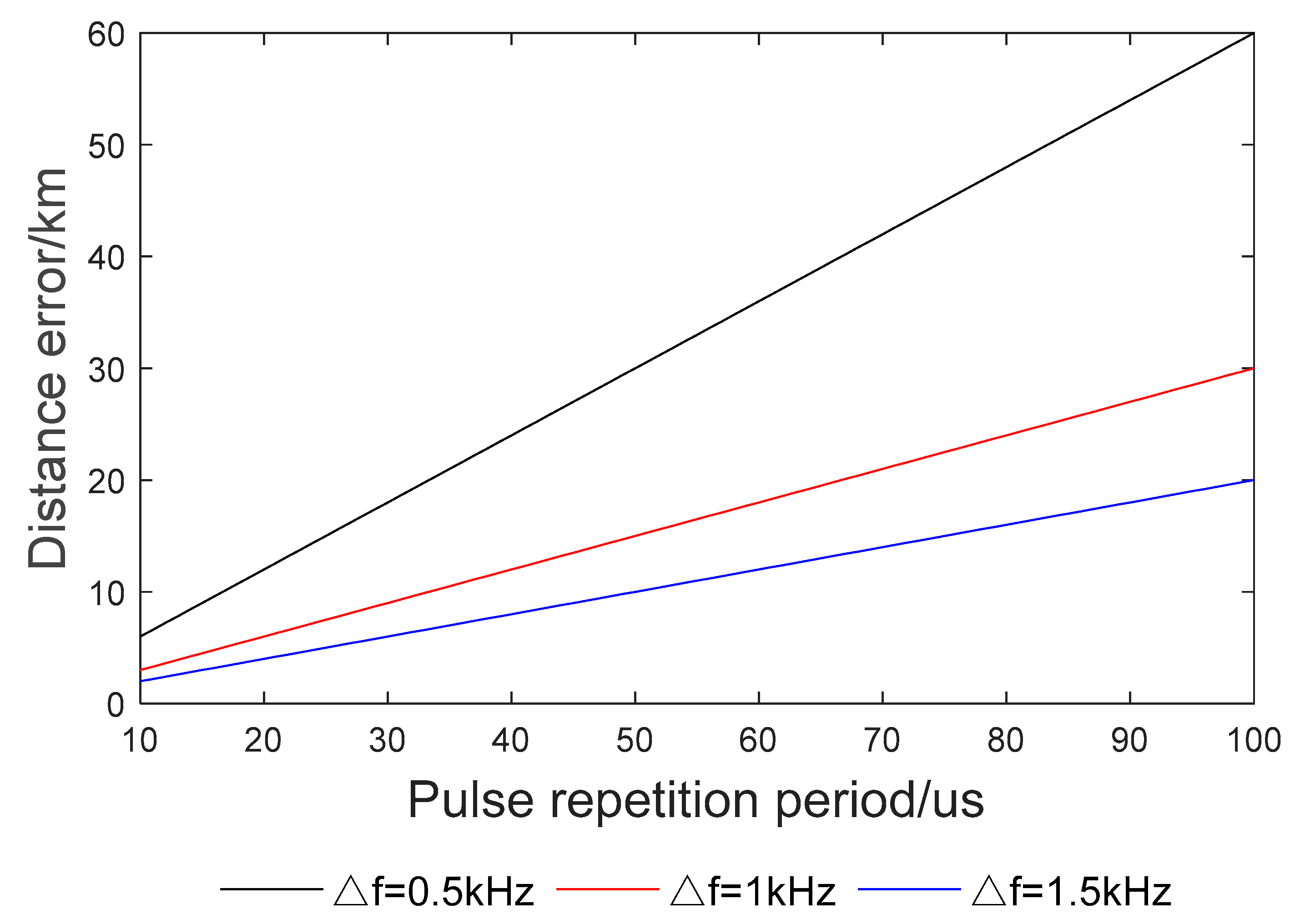
Figure 3.
MUSIC spectrum of conventional-stepped frequency.

Figure 4.
MUSIC spectrum of square-stepped frequency.
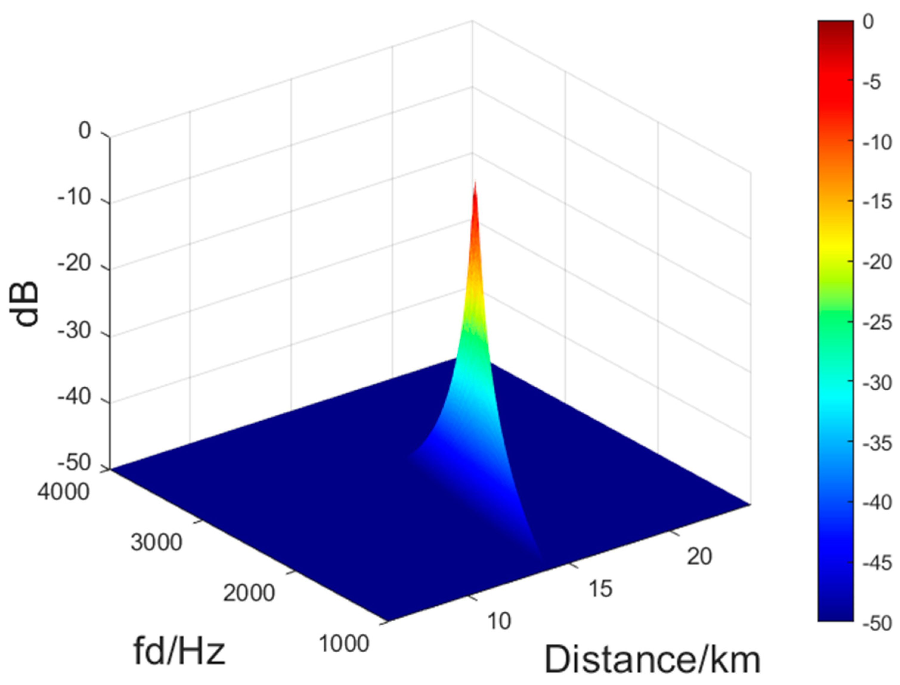
Figure 5.
Filter schematic diagram.
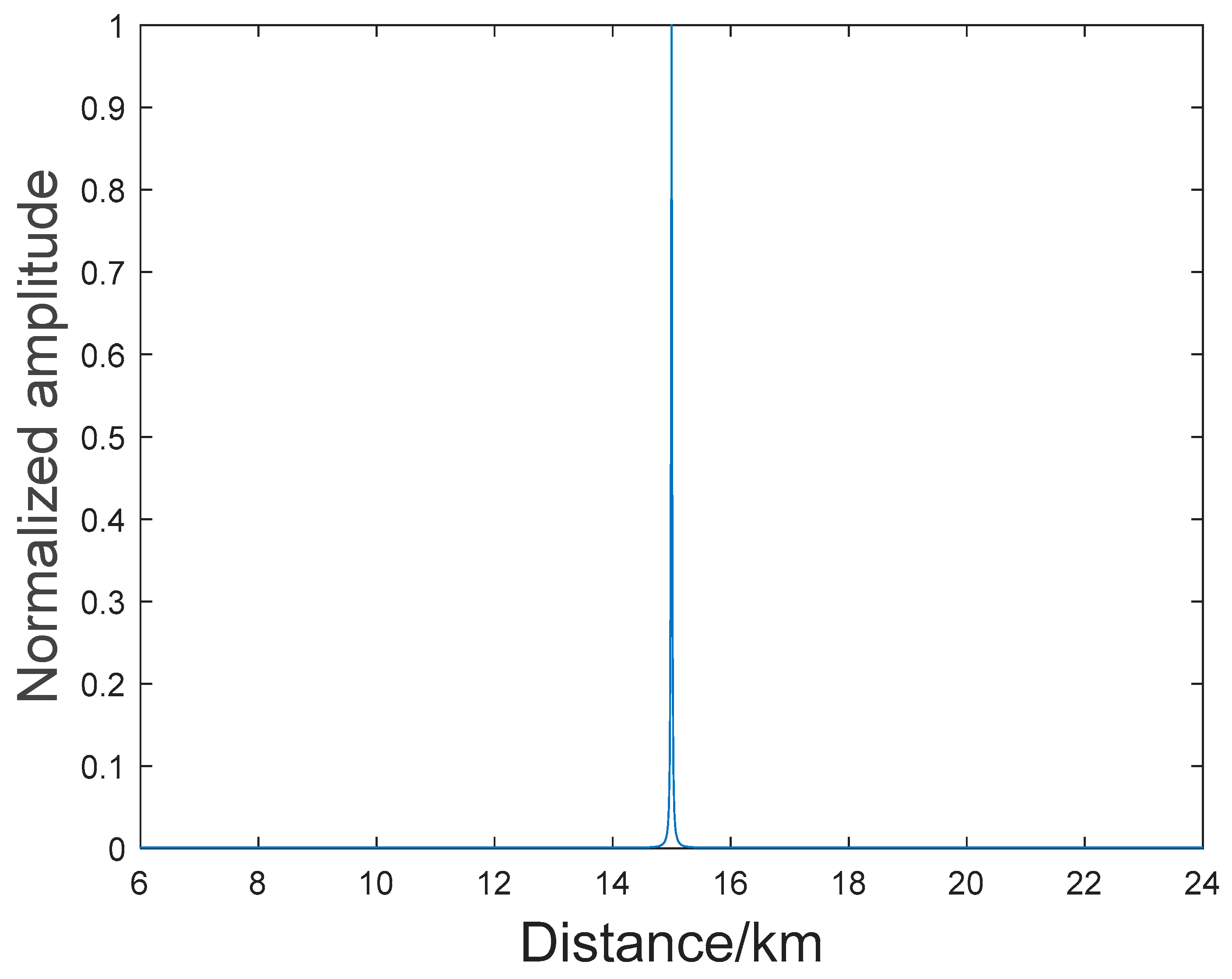
Figure 6.
False target suppression processing flow.
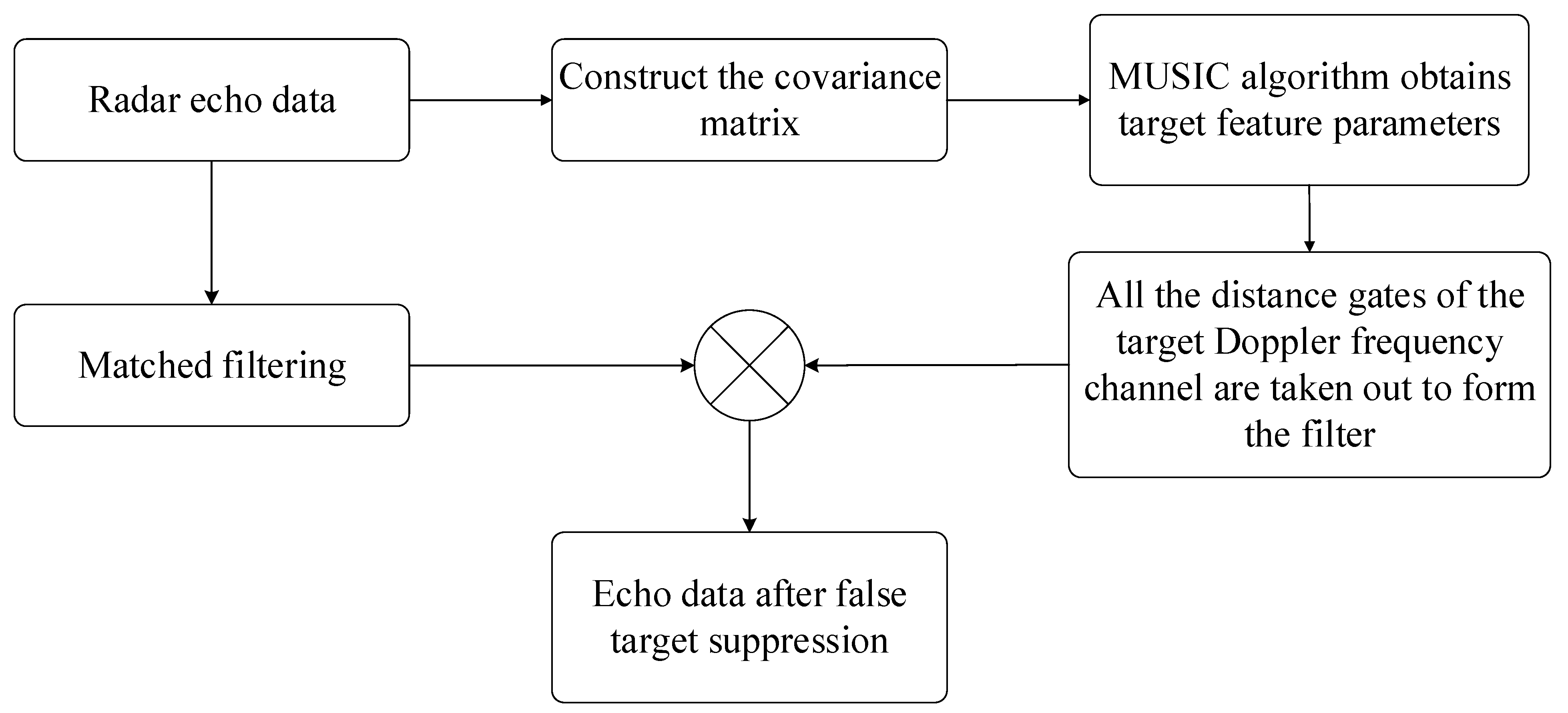
Figure 7.
Echo waveform after pulse compression.

Figure 8.
Filtered echo.

Figure 9.
Comparison of filters constructed with asynchronous feedforward.

Figure 10.
The maximum unambiguous range corresponding to asynchronous forward frequency.

Figure 11.
Analysis of the impact of input SNR on output SINR and compare with reference [26].
Figure 11.
Analysis of the impact of input SNR on output SINR and compare with reference [26].

Disclaimer/Publisher’s Note: The statements, opinions and data contained in all publications are solely those of the individual author(s) and contributor(s) and not of MDPI and/or the editor(s). MDPI and/or the editor(s) disclaim responsibility for any injury to people or property resulting from any ideas, methods, instructions or products referred to in the content. |
© 2023 by the authors. Licensee MDPI, Basel, Switzerland. This article is an open access article distributed under the terms and conditions of the Creative Commons Attribution (CC BY) license (https://creativecommons.org/licenses/by/4.0/).
Share and Cite
MDPI and ACS Style
Zhu, Y.; Zhang, Z.; Wang, X.; Li, B.; Liu, W.; Chen, H. A Method for Suppressing False Target Jamming with Non-Uniform Stepped-Frequency Radar. Electronics 2023, 12, 2534. https://doi.org/10.3390/electronics12112534
AMA Style
Zhu Y, Zhang Z, Wang X, Li B, Liu W, Chen H. A Method for Suppressing False Target Jamming with Non-Uniform Stepped-Frequency Radar. Electronics. 2023; 12(11):2534. https://doi.org/10.3390/electronics12112534
Chicago/Turabian StyleZhu, Yongzhe, Zhaojian Zhang, Xiaoge Wang, Binbin Li, Weijian Liu, and Hao Chen. 2023. "A Method for Suppressing False Target Jamming with Non-Uniform Stepped-Frequency Radar" Electronics 12, no. 11: 2534. https://doi.org/10.3390/electronics12112534
Note that from the first issue of 2016, this journal uses article numbers instead of page numbers. See further details here.