Article

Fabric–Metal Barrier for Low Specific Absorption Rate and Wide-Band Felt Substrate Antenna for Medical and 5G Applications

by
Fatimah Fawzi Hashim
1,2,
Wan Nor Liza Binti Wan Mahadi
1,2,*,
Tarik Bin Abdul Latef
1,2 and
Mohamadariff Bin Othman
1,2
1
Department of Electrical Engineering, University Malaya, Kuala Lumpur 50603, Malaysia
2
Electromagnetic Radiation & Devices Research (EMRD), Faculty of Engineering, University Malaya, Kuala Lumpur 50603, Malaysia
*
Author to whom correspondence should be addressed.
Electronics 2023, 12(12), 2754; https://doi.org/10.3390/electronics12122754
Submission received: 19 May 2023 / Revised: 14 June 2023 / Accepted: 19 June 2023 / Published: 20 June 2023
(This article belongs to the Section Microwave and Wireless Communications)

Abstract

:
This study proposed the dimensions of 55 mm × 34 mm × 1 mm for wearable antenna; the copper Y-slot patch and copper partial ground are attached to a felt substrate. The partial ground has the higher impact in antenna gain enhancement compared with the full ground, making it the most suitable candidate for wearable applications and suitable for embedding in fabrics for use in medical applications. In addition, the proposed antenna design combined a fabric–metal barrier operated at 2.4 GHz 65.4% with a low specific absorption rate (SAR) of 0.01 watts per kilogramme (W/kg) and 0.006 W/kg per 10 g and a gain of 6.48 dBi. The proposed antenna has an omnidirectional radiation pattern. The two-layer barrier is designed to achieve high electromagnetic (EM) absorption and reduce the antenna’s absorption coefficient (SAR) for safe use in applications involving human activities. Simulation and measurement results on the arm and the head of the human body indicated that the antenna has excellent performance. In addition, the measurement results agreed well with the simulation results, making the proposed wearable antenna reliable for medical and 5G applications.

1. Introduction

The efficiency of wearable antennas is one of the most important components that are improving due to their role as an essential component in devices associated with human activities, the most important of which are health applications. These devices can monitor blood sugar, blood pressure, heart rate, and other vital signs and transmit this data to the appropriate health authority in accordance with patients in order for them to take appropriate action when necessary [1,2,3,4,5,6]. Devices like these have been made wearable and are sometimes even built into clothes because they are so useful for people.
When wearing wearable antennas, it is possible to observe that the human body has a detrimental effect on antenna performance. The human body’s layers—skin, fat, muscle, and bone—absorb the signal, leading to an unintended consequence. The antenna’s reflection coefficient (S11), bandwidth (BW), gain (dBi), and radiation properties are all affected by these tissues’ high dielectric constants [7,8].
The use of EBG structures is just one of many methods that have been created to lessen the impact of the human body on antenna efficiency. Most contemporary antenna designs employ the well-known electromagnetic band gap (EBG) construction. One of its advantages is its separation from the human body [9].
It is essential to keep in mind that the transmission of electromagnetic waves by wearable antennas has a negative effect on human health when discussing devices that come into close proximity with the body.
Electric and magnetic fields change over time, but electromagnetic and radio waves (radiation) travel through space at the speed of light and in a path perpendicular to those fields. The thermal effects can be evaluated using the specific absorption rate (SAR), which is defined as the quantity of energy deposited per kilogram of body weight. Because of the potential for damaging biological effects, assessing the SAR value in a human body is not without its caveats; instead, numerical models should be used to determine the SAR [10].
SAR is a unit to determine the rate of how much energy from an electromagnetic source is absorbed per mass unit by human tissues, as show in Equation (1) [11]:
S A R = σ E i 2 ρ   ( W / kg )
where:
σ—is the conductivity of tissue in unit (S/m).
E—is the electric field intensity in unit (V/m).
ρ—is the mass density of tissue in unit (kg/m3).
Either the entire body or a tiny volume is averaged in the SAR (typically, 1 g or 10 g of tissue). SAR is expressed in terms of watts per kilogram. Limits for specific absorption rate (SAR) are set at 2 W/kg over 10 g by the International Commission on Non-Ionizing Radiation Protection (ICNIRP) and the IEEE C95.1-2019 guidelines, and at 1.6 W/kg over 1 g by the Federal Communications Commission (FCC) [12].
There are numerous sources that address the pros and cons of using SAR and PD parameters. Some of these citations favor SAR, while others favor PD. In this work, the FCC-approved SAR is used, with the (PD) unit applied to distances greater than or equal to 5 cm.
Recent research suggests that continuous wireless radiation has biological effects, and this is particularly true when millimeter waves, a higher frequency, more transmitters, and more connections are taken into account, as they are in 5G.
Genotoxicity (DNA damage), cell proliferation, gene expression, cellular signaling, electrical activity, and membrane impacts are all influenced by mmW frequency.
Two different frequency bands, FR1 (below 6 GHz) and FR2 (above 6 GHz), make up the 5G (5th generation cell network) (mmWave). FR1’s coverage is significantly larger because it works at lower frequencies (410–7125 MHz) than FR2. Using millimeter-wave frequencies (24,250 to 52,600 MHz), FR2 is capable of transmitting data at higher speeds and with more storage space than its predecessor, FR1.
The H-bond in cellular macromolecules may be disrupted by weak fields because of accelerated electron transport. The observed upregulation of transcription and protein translation following RF-EMF exposure may have a biological basis [13]. The energy of weak EM fields, on the other hand, is not enough to immediately break a chemical bond in DNA. It is now clear that oxygen radicals (ROS) or disruption of DNA repair processes are the end result of genotoxic effects caused by indirect mechanisms.
Exposure to RF-EMW has been linked to changes in plasma membrane potential and calcium efflux, followed by a decrease in calcium and a drop in protein kinase C activity (PKC). Apoptosis is induced, and a wide variety of enzymes, ion transporters, channels, and proteins are altered as a result of this reduction. By disrupting mitochondrial membrane-bound NADH oxidase, RF-EMW causes the generation of reactive oxygen species (ROS). Apoptosis, DNA, and the chaperonins PKC and histone kinase are all affected by reactive oxygen species [14]. Heat Shock Protein (HSP) increases in response to electromagnetic radiation (EMR) and ROS [14,15].
Since there is not much known about how 5G affects the health of people, plants, animals, insects, and microbes, it is best to be careful. Because of this, it is very important for 5G applications, especially those that are close to the body, to have a low SAR.
The specific absorption rate (SAR) is also considerably lowered to conform with regulations set forth by the Federal Communications Commission (FCC) and the International Commission for Non-Ionizing Radiation Protection (ICNIRP) [16]. However, these buildings have a few drawbacks, the most important of which is their typically thick thickness when applied to Medical Body Area Networks (MBANs) [7,16]. Furthermore, frequency shifts are the most significant drawback of EBG systems due to their limited bandwidth [17]. When the transmitter is in close proximity to a person’s skin, this flaw becomes especially noticeable. As the signal from the antenna moves through the body’s tissues, it becomes weaker and its pattern becomes messed up. With a wide bandwidth, frequency changes have less of an impact on the target band, which can stay within a 10-dB tolerance range. In addition, high data rates and close-range indoor interactions demand a lot of bandwidth [18].
In [19,20], the authors presented high-performance antennas for medical application. In [21,22], many of the antennas presented in this field were discussed in terms of their specifications and method of design, in addition to the real possibility of employing this type of antenna in medical applications, so it is possible to refer to their use in medical applications, the effectiveness of their performance, and applications involving wearable technology.
In [23], a defected ground structure (DGS) antenna in the form of an E-shaped patch was attached onto the rear of an EBG array to expand its frequency. While this research did succeed in achieving a large bandwidth, the inclusion of a supported approach like DGS is not a test of the EBG method. When attached solely to the antenna, this method still has a limited capacity. In addition, the suggested design’s size and weight went up after the addition of the (DGS) structure. In [24], the proposed antenna was designed to be compacted with EBG 2 × 8 and 8 × 8 arrays to operate at 77.1–84.6 GHz (9.3%), 78.6–84.9 GHz (7.7%), 73.1–85.3 GHz (15.1%), and 76.8–84.4 GHz (9.4%). The designed antenna in [25] was attached to an EBG array to achieve wide bandwidth at (3.04–4.70 GHz) 42.89%. In [26], the antenna of size 46 mm × 46 mm × 1.6 mm was designed for 5G new radio (NR) sub-6 GHz n77/n78/n79 and 5 GHz WLAN with good impedance matching. The designed antenna attached to the electromagnetic bandgap (EBG) structure—defected ground structure (DGS)—to operate at a wide frequency range of 3.2–5.75 GHz.
In [27], a 2 × 1 EBG array was printed on the designed antenna ground with a compact size of 8 × 8 mm2, with a low SAR 0.695 W/Kg for 1 g; the antenna over the EBG structure covered the frequency range from 3.1 to 10.6 GHz.
In [28], a modified meandered slot, a slotted Y-shaped monopole, and a trident-shaped feed strip with a FR-4 substrate with a total size of 30 × 20 × 1.6 mm3 was presented to achieve a wide bandwidth 41.8% at 2.6 GHz and gain 3 dBi with attaching a metallic reflector of size 60 × 60 mm2 for 5G, Wi-Fi, and WiMAX applications.
In [29], a study into a Y-shaped patch antenna for use at 4, 19, and 13 GHz is conducted. Gains were found to be 5.01, 5.42, and 7.46 dBi at the three resonant frequencies, with bandwidths of 9.99%, 4.55%, and 7.62%. The suggested antenna can be used in a variety of radio, satellite, and airborne radio navigation systems.
In this study, we proposed a wearable antenna Y-slot patch with a fabric–metal barrier designed for SAR reduction to provide the highest levels of safety for human health when the proposed antenna is used in medical and 5G applications.

2. Antenna Design and Parametric Study

The proposed antenna has a light weight and dimensions of 55 by 34 by 1 mm. The fabric substrate was 0.7 mm thick, and a 0.17 mm thick copper Y-slot patch was fixed to it. The antenna’s gain was increased by including a partial ground on the antenna’s cloth substrate, which was 0.17 mm thick. Figure 1 depicts the proposed antenna patch evaluation starting from the classical square-shaped antenna. Figure 2 illustrates S11 for the antenna in different patch shapes: (a) classical square slot presented as a red dashed line, (b) T-slot patch presented as a dashed black line, and (c) Y-slot patch presented as a solid black line. In both the classical patch square slot antenna and T-slot antenna the operating frequency was at lower frequencies 0.5 GHz–1.8 GHz and 1.4 GHz–1.6 GHz, respectively. However, the Y-shaped slot patch shows a fixed operating frequency at center frequency at 2.4 GHz with wide bandwidth 67.5% and gain 6.8 dBi. Figure 3 shows the simulated gain in dBi. The simulated results show that the designed antenna has gain 6.8 dBi at 2.4 GHz and an omnidirectional radiation. Figure 3 and Figure 4 illustrate antenna simulation gain and radiation pattern in H-field and E-field, respectively.
Felt, blue jeans, and polyester were among the fabrics used in the antenna tests. Figure 5 displays the S11 for the various fabric substrates in size (55 × 34 × 0.7) mm3, with the best outcomes achieved by the felt substrate in terms of both operating frequency (2.4 GHz) and wide bandwidth, which is presented as a black solid line. Therefore, the purpose of this research was to identify a frequency in the ISM band with a particularly broad bandwidth for use in commercial, scientific, and medical applications. In Figure 5, the dashed black line presents the S11 for the Jeans substrate ( ε r = 1.7 tan δ = 0.025) which shows that the antenna with jeans substrate has a narrower band width at 2.4 GHz compared with the felt substrate. The dashed red line presents the antenna S11 with polyester substrate parameters ( ε r = 1.9 tan δ = 0.0045) which shows the antenna operating from 0.1 GHz–2.3 GHz. The input impedance is very sensitive to the breadth of the strip feeder. The resonance frequency drops as the feeder breadth grows larger because of changes in antenna length (L) and effective dielectric constant ε e .
The input impedance at resonance decreases from 125 Ω to 50 Ω because the radiation from the radiating edge increases, which decreases the radiation resistance. The following impacts are seen as the strip line height (h) increases. The strength of the edge surrounding the fields grows as h rises [29], lengthening the extension, and the useful length makes the resonance frequency smaller. On the other hand, as h grows longer, the W/h ratio falls, lowering the effective dielectric constant ε e and raising the operating frequency. However, the effect of the increase in ∆L is dominant over the decrease in ε e . Therefore, the net effect is to decrease the resonance frequency.
A rectangular Y-slot patch microstrip antenna was analyzed as a parallel combination of resistance (R), inductance L, and capacitance CP. The most important thing that controlled S11 was the number of Y-slots on the emitting element that could be opened and closed. The existing distribution was changed by them. So, the radiating element has two currents: one straight current like that found in any conventional radiating patch, and another, more circuitous current that follows the Y-slots. This caused a decrease in the harmonic frequency. Figure 6 illustrates the fabricated antenna (a) back view and (b) front view. According to the modal expansion cavity model, the values of R, L, and C [30] were calculated using the Formulas (2)–(5):
C = ε 0 ε r L W 2 H cos 2 Y 0 π 2 H
L = 1 ω 2 C
ε e = ( ε r + 1 ) 1 + ( ε r 1 ) 1 ( 1 + 10 H W ) 1 2
F = C 2 π L ε e
where:
F—is the resonance frequency of the antenna.
L—is the length of the patch.
W—is the width of the patch.
H—is the total high of the antenna.
Y0—is the length of the vertical portion of the feed point.
ε r —is the relative permittivity of the substrate.
ε e —is the effective dielectric constant.

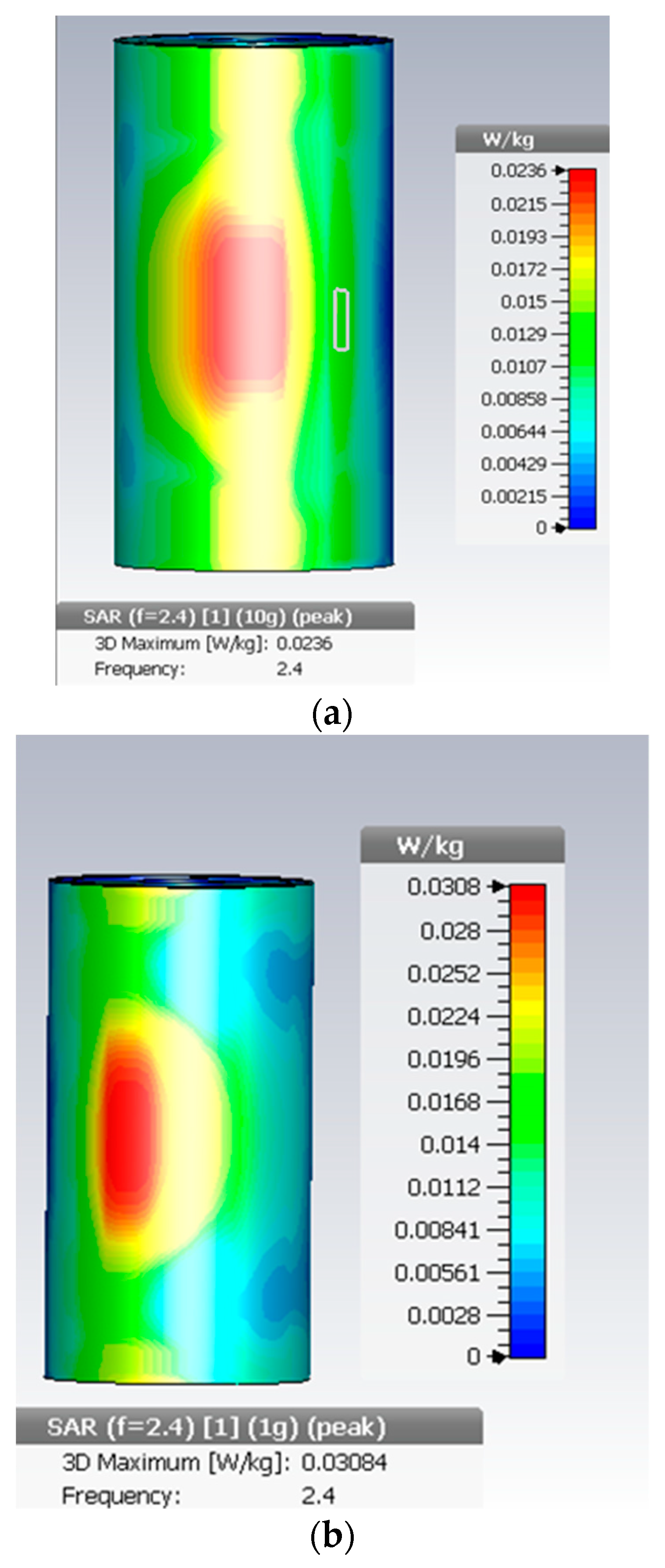
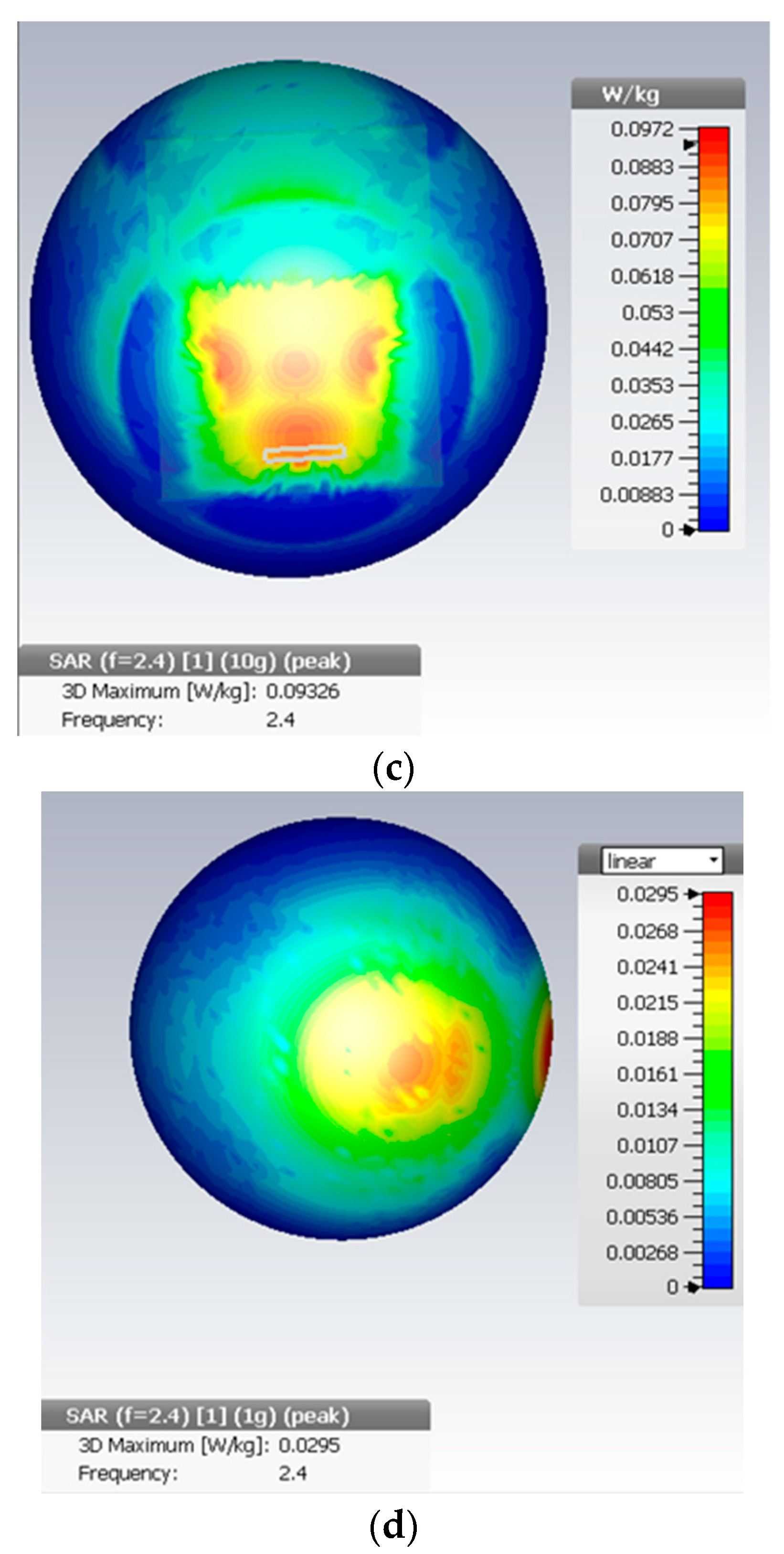
3. Antenna Performance and SAR Evaluation (in Free Space/on Human Body)

To accommodate today’s gadgets, the antenna’s size must be taken into account. When applied to the human body, antennas must be small in size and have a broad bandwidth to combat the body’s natural susceptibility to resonant frequencies. That is why the authors of this research advocated for a felt substrate and a partial ground for a wearable antenna.
Figure 7 shows that the antenna’s free space simulation findings agree with the measured S-parameter test results. Using a Vector Network Analyzer ZV 24 VNA (10 MHz–24 GHz), we were able to determine that the proposed Y-slot cloth antenna has a gain of 6.78 dBi at its center frequency of 2.45 GHz and is omnidirectional over a frequency range of 1.757 GHz to 3.328 GHz. This broad operating frequency range is due to the antenna’s low permittivity substrate, the fact that the properties of the felt dielectric permittivity (εr = 1.22, loss tangent of 0.016) match the resonant frequency range (2.3 GHz–2.8 GHz) [31], and the novel design of a Y-slot patch on cloth. It may also be explained by a reduction in the stimulation of surface waves. In order to increase bandwidth, it is necessary to reduce the quality factor (Q factor) of the strip feeder and the stored energy [26,32]. With some possible exceptions related to the making or soldering process, the measured results match the simulated results. This wider bandwidth is helpful for wearable antennas because it makes sure that the desired frequency band is covered, even if the frequency changes, because of how the body moves. Small differences between what was measured and what was simulated are likely caused by mistakes made by humans when making or soldering the device.
The proposed antenna felt substrate was measured on the arm of a female, who weighed 74 kg and stood 167 cm tall. Figure 8 shows that the S11 results of the antenna when placed on a human arm and head were compared with measured S11 in free space to prove the effectiveness of the designed antenna in real life. The proposed antenna demonstrated a sufficiently wide bandwidth from 1.65 GHz to 3.132 GHz to cover the operating frequency at 2.4 GHz without shifting. While using the intended antenna on a human arm, the bandwidth was reduced from 65% to 59.28% due to absorption, the aforementioned blockage effect, and an increase in front-to-back ratio (FBR), which is caused by the body’s higher permittivity than the substrate antenna material.
As a result, radiation directed at the surface of the human body is significantly reduced, and the antenna’s overall gain and front-to-back ratio also show improvements (FBR) [7,33,34,35,36]. This antenna also produces omnidirectional radiation, which has been linked to an increase in dangerous human applications [37,38]. Nevertheless, Section 4 discusses the proposed solution and the laboratory experiment.
Artificial magnetic conductors (AMCs), also called electromagnetic band gap structures (EBG), and high impedance surfaces are two examples of modern techniques that help reduce SAR and are being developed to make antennas safer [39,40].
For the SAR evaluation in this study, we use wave-absorbing materials. Wave-absorbing materials can efficiently absorb EM radiation, decrease EM pollution, safeguard all forms of electrical and electronic equipment from EM interference, maintain the normal operation of equipment, avoid equipment failure or deterioration, and effectively protect the human body. In order to stop EM radiation from damaging the human body in a high-radiation environment, it is one of the most crucial strategies to regulate EM wave transmission and stop EM wave pollution [41].
In order to maximize the use of absorbing materials in the design of wave-absorbing materials, the metal substrate is typically added to the bottom of the material in order to achieve strong reflection. As shown in Figure 9, when transmitted waves strike the surface of a metal substrate, they are reflected back onto the wave-absorbing material for absorption loss [41].
The complex dielectric constant, complex permeability, and loss angle tangent of a material are the main things that affect how well it absorbs. Wave-absorbing fabrics work because they absorb electromagnetic waves, which causes the fabric to lose some of its shape. The electromagnetic parameters of wave-absorbing materials are crucial in computing the absorption rate. In addition, transmission line theory can be used to calculate the fabric’s absorptivity (6)–(12) [42]:
( d B ) = 20 log | Z i n Z 0 Z i n + Z 0 |
Z i n = Z 0 μ g ε 0 tanh [ j ( 2 π f d c ) μ g ε g ]
Z 0 = μ 0 ε 0
ε = ε j ε
μ = μ j μ
t a n δ ε = ε / ε
t a n δ μ = μ / μ
where:
R: reflection coefficient.
Z i n : input impedance.
Z 0 : free space impedance.
f: frequency.
c: the propagation speed of EM waves in a vacuum.
d: material thickness.
μ g and ε g : complex permeability and permittivity of absorbing material, respectively.
μ 0 and ε 0 : complex permeability and permittivity in free space.
ε and ε : the real and imaginary parts of complex permittivity.
μ and μ : the real and imaginary parts of complex permeability.
tan   δ ε and tan δ μ : the tangent of dielectric loss angle and magnetic loss angle.
In this study, we aim to make the design and manufacturing process simple and inexpensive while preserving the small compressed antenna’s size. The absorbing barrier that absorbs the EM waves emitted by the antenna is composed of two layers as shown in Figure 10; the first of which is a one-millimeter-thick cotton layer and the second of which is a one-millimeter-thick copper layer, as cotton represents the absorbing layer and copper represents the reflective metal, in order to achieve a simple-to-manufacture installation with properties similar to 3D woven absorbing materials.
Figure 11 shows (a) the illustration of the equivalent circuit for the two-layer barrier, (b) the absorption of EM percentage in the cotton layer, and (c) the electric fringing field on the copper layer.
The arm and head models were simulated to represent the two areas of the human body that are most at risk of harm when using mobile devices and equipment intended to keep track of one’s health, such as some smart wristbands, watches, and cell phone accessories.
CST 2014 (computer simulation technology) software was used to simulate the arm and head model to test the effectiveness of the suggested antenna. The human body’s structure is represented by a four-layer diagram. The length of the limb was a cylindrical 150 × 80 mm2 in total. The four-layer limb model is summarized in Table 1. Moreover, a sphere with 85 mm radius of four layers was designed to mimic the human head, as these four layers consist of the brain covered by the skull (bone), then fat, and finally the skin layer. The characteristics of these layers are shown in the Table 2 [43]. Additionally, Figure 12 shows (a) the simulated arm and (b) the simulated head model.
The cotton side of the absorbing barrier was attached directly to the antenna ground and the copper side was in contact with the skin layer of the arm and head model. The antenna over a 2 mm absorbing barrier achieved a satisfactory result of 0.02 W/kg for 10 g and 0.03 W/kg for 1 g at 0 distance from the arm model and 0.097 W/kg for 10 g and 0.0295 W/kg with direct contact with the head mode. Figure 13a,b shows the simulation results for the arm model with a 2-mm barrier and (c) and (d) illustrate the simulation result for the head model with a 2-mm barrier.
The benefit of this technique is that the antenna can be applied directly onto the human skin layer without impacting it. The results of applying the absorption barrier are also very satisfactory because they were significantly lower than both the international limits and the values attained in some recently published studies, as shown in Table 2. While studies have demonstrated that some copper bracelets relieve arthritic pain, others have not supported this beneficial effect of copper. The copper layer in contact with the skin layer does not hurt the wearer. Yet, there is no data or proof demonstrating the risk of skin contact with copper.

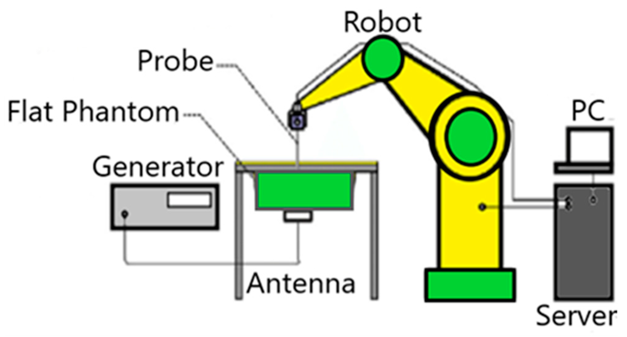
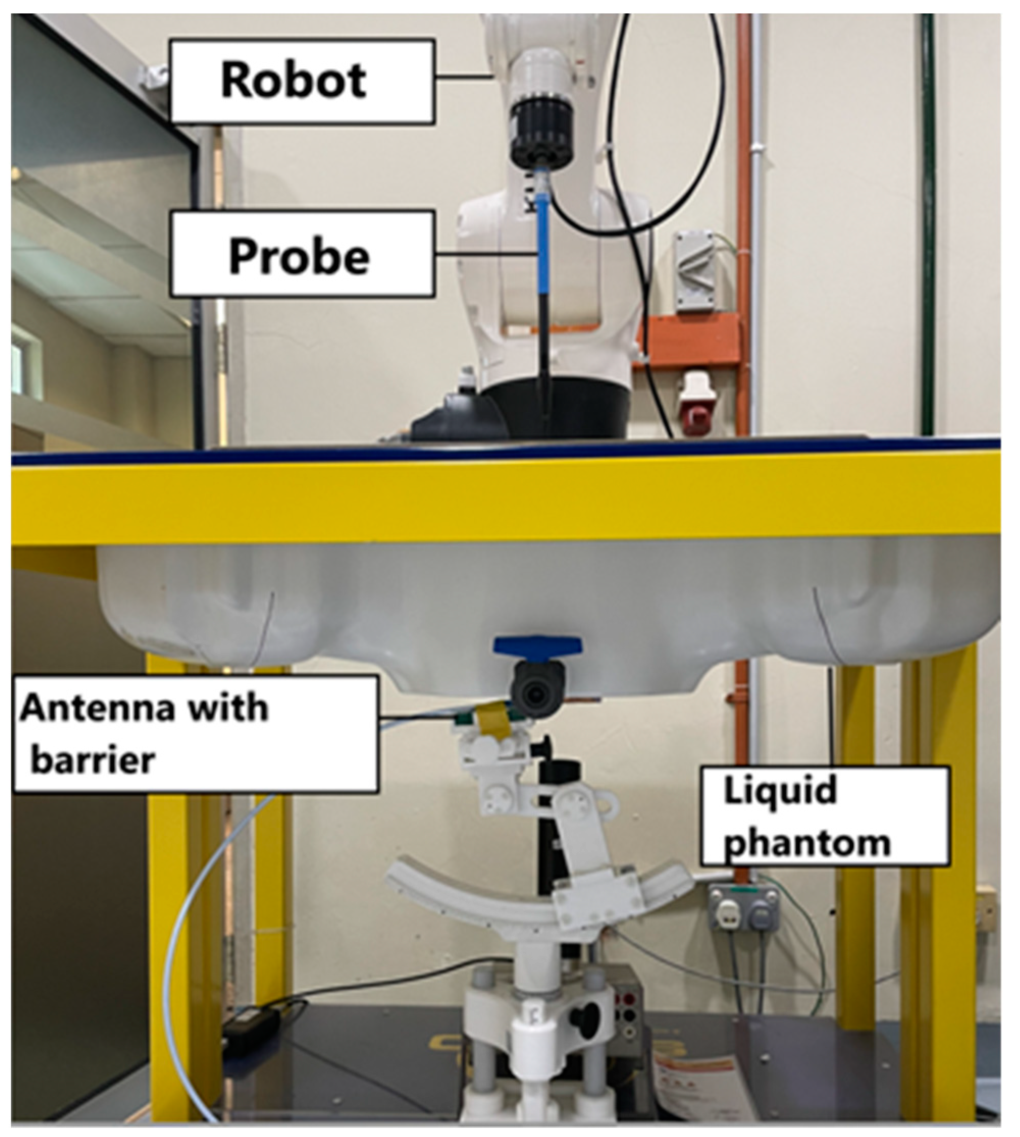
4. Sar Measurements in Flat Phantom

Actual SAR measurements heavily rely on power analysis. The antennas are not exactly matched, and there are losses between the power given to and the power taken from them. As a result, the approved power must be monitored and used as the standard to ensure consistency across simulations and measurements. Its power is distributed as 0.25 W to the low band and 0.13 W to the high band [16].
Figure 14 depicts the setup for measurement: A signal generator produces the signal that is amplified and transmitted through a directional coupler. A power monitor is used to monitor the required feeding power for the SAR calculation. A robotic arm, electric field probes, and a customized head tank are used to measure SAR. The tank contains a unique fluid (head phantom) designed to mimic human tissue characteristics. The antenna is positioned below the tanks to mimic its position close to the head during actual use. Moreover, the liquid phantom (head phantom) recipe is in shown in Table 3.
The electrical field probe moves through the liquid phantom to find the SAR peak’s approximate area. It is recommended that the phantom be placed further away from the probe than the radius of the probe. The zoom scan comes next. The aim of the zoom scan is to find the mean SAR over the cube. After that, zoom scans are done around one or more of these peak places to find the peak spatial average SAR value.
The experiment was conducted in two ways: measuring the absorption coefficient of the antenna when it was directly applied to the phantom, and installing the barrier directly with the phantom and installing the antenna directly on the barrier.
With the antenna attached directly to the phantom, the absorption coefficient was found to be 11.57 W/g per gram and 5.58 W/g per ten grams; this value of the absorption coefficient is not often approved for human use due to the many negative health impacts it has on humans.
The second part of the experiment obtained the values 0.011 W/g per 1 g and 0.006 W/g per 10 g after the implementation of the two-layer barrier; it shows a significant reduction. These values acquired for the absorption coefficient are the values that we aim to obtain in this work for the safe use of the substance in human applications, as the value of the absorption coefficient is essential to the safety of the substance. This improvement is attributable to the two-layer barrier, the first of which is the fabric, which absorbs the majority of the EM, and the second of which is the copper layer, which reflects the EM away from the human body. Figure 15 illustrates the experimental setup in the lab.
The results of laboratory measurements are fully compatible with the simulation results for the adoption of the two-layer barrier technology in reducing the absorption coefficient to nearly zero, nominating this technology for adoption in fifth-generation technologies to ensure the safe use of antennas in applications involving human activities. Table 4 presents the obtained SAR simulation and measured results with recently published research, and newly released studies are compared to this work in Table 5.

5. Conclusions

For 2.4 GHz medical and 5G applications, a Y-slot patch antenna made of felt with a partial ground was proposed. The antenna was tested on a live human being and in free space. The effectiveness of the proposed design was demonstrated using free space and human body measurements, both of which are common techniques for evaluating antennas. In addition, both the free space and human body results were positive and in excellent agreement with the simulation results. High performance was shown by measuring a human arm and head, which showed a bandwidth of 65.4% and a gain of 6.48 dBi. The findings confirmed that the proposed antenna with a felt substrate could reduce the detrimental frequency-shifting impact of the human body on antenna radiation. The SAR values reduced after applying the new concept of the fabric–metal barrier from 11.57 W/g per 1 g and 5.58 W/g per 10 g to 0.01 W/kg for 1 g and 0.006 W/kg for 10 g. It was therefore found to be safe for human activity applications, rendering the design as safe for use and appropriate for wearable applications.

Author Contributions

Conceptualization, F.F.H.; Software, F.F.H.; Writing—original draft, F.F.H.; Supervision, W.N.L.B.W.M., T.B.A.L. and M.B.O. All authors have read and agreed to the published version of the manuscript.

Funding

This research received no external funding.

Conflicts of Interest

The authors declare no conflict of interest.

References

  1. Ashap, A.Y.I.; Abidin, Z.Z.; Dahlan, S.H.; Majid, H.A.; Yee, S.K.; Saleh, G.; Malek, N.A. Flexible Wearable Antenna on Electromagnetic Band Gap using PDMS substrate. Telecommun. Comput. Electron. Control 2017, 15, 1454. [Google Scholar] [CrossRef] [Green Version]
  2. Ashyap, A.Y.I.; Marzudi, W.N.N.W.; Abidin, Z.Z.; Dahlan, S.H.; Majid, H.A.; Kamaruddin, M.R. Antenna incorporated with Electromagnetic Bandgap (EBG) for wearable application at 2.4 GHz wireless bands. In Proceedings of the 2016 IEEE Asia-Pacific Conference on Applied Electromagnetics (APACE), Langkawi, Malaysia, 11–13 December 2016; pp. 217–221. [Google Scholar] [CrossRef]
  3. Muhammad, Z.; Shah, S.M.; Abidin, Z.Z.; Asyhap, A.Y.I.; Mustam, S.M.; Ma, Y. CPW-Fed Wearable Antenna at 2.4 GHz ISM Band; AIP Publishing LLC.: Melville, NY, USA, 2017; p. 020003. [Google Scholar] [CrossRef] [Green Version]
  4. Gao, G.-P.; Yang, C.; Hu, B.; Zhang, R.-F.; Wang, S.-F. A Wide-Bandwidth Wearable All-Textile PIFA With Dual Resonance Modes for 5 GHz WLAN Applications. IEEE Trans. Antennas Propag. 2019, 67, 4206–4211. [Google Scholar] [CrossRef]
  5. Ashyap, A.Y.I.; Abidin, Z.Z.; Dahlan, S.H.; Majid, H.A.; Kamarudin, M.R.; Abd-Alhameed, R.A. Robust low-profile electromagnetic band-gap-based on textile wearable antennas for medical application. In Proceedings of the 2017 International Workshop on Antenna Technology: Small Antennas, Innovative Structures, and Applications (iWAT), Athens, Greece, 1–3 March 2017; pp. 158–161. [Google Scholar] [CrossRef]
  6. Alani, S.; Zakaria, Z.; Ahmad, A. Miniaturized UWB elliptical patch antenna for skin cancer diagnosis imaging. Int. J. Electr. Comput. Eng. 2020, 10, 1422–1429. [Google Scholar] [CrossRef]
  7. Jiang, Z.H.; Brocker, D.E.; Sieber, P.E.; Werner, D.H.; Compact, A. Low-Profile Metasurface-Enabled Antenna for Wearable Medical Body-Area Network Devices. IEEE Trans. Antennas Propag. 2014, 62, 4021–4030. [Google Scholar] [CrossRef]
  8. Soh, P.J.; Vandenbosch, G.; Wee, F.H.; van den Bosch, A.; Martinez-Vazquez, M.; Schreurs, D. Specific Absorption Rate (SAR) Evaluation of Textile Antennas. IEEE Antennas Propag. Mag. 2015, 57, 229–240. [Google Scholar] [CrossRef]
  9. Ashyap, A.Y.I.; Abidin, Z.Z.; Dahlan, S.H.; Majid, H.A.; Seman, F.C. A Compact Wearable Antenna Using EBG for Smart-Watch Applications. In Proceedings of the 2018 Asia-Pacific Microwave Conference (APMC), Kyoto, Japan, 6–9 November 2018; pp. 1477–1479. [Google Scholar] [CrossRef]
  10. Alkhalaf, H.Y.; Ahmad, M.Y.; Ramiah, H. Self-Sustainable Biomedical Devices Powered by RF Energy: A Review. Sensors 2022, 22, 6371. [Google Scholar] [CrossRef]
  11. Lak, A.; Adelpour, Z.; Oraizi, H.; Parhizgar, N. Design and SAR assessment of three compact 5G antenna arrays. Sci. Rep. 2021, 11, 21265. [Google Scholar] [CrossRef]
  12. Agarwal, K.; Guo, Y.-X.; Salam, B. Wearable AMC Backed Near-Endfire Antenna for On-Body Communications on Latex Substrate. IEEE Trans. Compon. Packag. Manuf. Technol. 2016, 6, 346–358. [Google Scholar] [CrossRef]
  13. Kheifets, L.; Repacholi, M.; Saunders, R.; van Deventer, E. The Sensitivity of Children to Electromagnetic Fields. Pediatrics 2005, 116, e303–e313. [Google Scholar] [CrossRef] [Green Version]
  14. Nylund, R.; Leszczynski, D. Mobile phone radiation causes changes in gene and protein expression in human endothelial cell lines and the response seems to be genome- and proteome-dependent. Proteomics 2006, 6, 4769–4780. [Google Scholar] [CrossRef]
  15. Olakunle, A.; Kayode, J.; Adewale, F. Overview of Cellular Damage in Abnormal Absorption of Magnetic and Radio Waves: Implications among Cell-Phone Users. Available online: https://www.researchgate.net/publication/287643628 (accessed on 30 December 2015).
  16. Qian, Y.; Yang, Y.F.R.; Itoh, T. Novel Planer band gab structures forfor antenna applications. In Proceedings of the AP2000 Millennium Conferance on Antenna and Propagation, Davos, Switzerland, 9–14 April 2000. [Google Scholar]
  17. Salonen, P.; Hurme, L. A novel fabric WLAN antenna for wearable applications. In Proceedings of the IEEE Antennas and Propagation Society International Symposium. Digest. Held in conjunction with: USNC/CNC/URSI North American Radio Sci. Meeting (Cat. No.03CH37450), Columbus, OH, USA, 11 August 2003; pp. 700–703. [Google Scholar] [CrossRef]
  18. Ashyap, A.Y.I.; Abidin, Z.Z.; Dahlan, S.H.; Majid, H.A.; Kamarudin, M.R.; Alomainy, A.; Abd-Alhameed, R.A.; Kosha, J.S.; Noras, J.M. Highly Efficient Wearable CPW Antenna Enabled by EBG-FSS Structure for Medical Body Area Network Applications. IEEE Access 2018, 6, 77529–77541. [Google Scholar] [CrossRef]
  19. Alibakhshikenari, M.; Virdee, B.S.; Shukla, P.; Parchin, N.O.; Azpilicueta, L.; See, C.H.; Abd-Alhameed, R.A.; Falcone, F.; Huynen, I.; Denidni, T.A.; et al. Metamaterial-inspired antenna array for application in microwave breast imaging systems for tumor detection. IEEE Access 2020, 8, 174667–174678. [Google Scholar] [CrossRef]
  20. Alibakhshikenari, M.; Virdee, B.S.; See, C.H.; Shukla, P.; Moghaddam, S.M.; Zaman, A.U.; Shafqaat, S.; Akinsolu, M.O.; Liu, B.; Yang, J.; et al. Dual-Polarized Highly Folded Bowtie Antenna With Slotted Self-Grounded Structure for Sub-6 GHz 5G Applications. IEEE Trans. Antennas Propag. 2022, 70, 3028–3033. [Google Scholar] [CrossRef]
  21. Alibakhshikenari, M.; Virdee, B.S.; Azpilicueta, L.; Naser-Moghadasi, M.; Akinsolu, M.O.; See, C.H.; Liu, B.; Abd-Alhameed, R.A.; Falcone, F.; Huynen, I.; et al. A Comprehensive Survey of “Metamaterial Transmission-Line Based Antennas: Design, Challenges, and Applications. IEEE Access 2020, 8, 144778–144808. [Google Scholar] [CrossRef]
  22. Alibakhshikenari, M.; Ali, E.M.; Soruri, M.; Dalarsson, M.; Naser-Moghadasi, M.; Virdee, B.S.; Stefanovic, C.; Pietrenko-Dabrowska, A.; Koziel, S.; Szczepanski, S.; et al. A Comprehensive Survey on Antennas On-Chip Based on Metamaterial, Metasurface, and Substrate Integrated Waveguide Principles for Millimeter-Waves and Terahertz Integrated Circuits and Systems. IEEE Access 2022, 10, 3668–3692. [Google Scholar] [CrossRef]
  23. Ashyap, A.Y.I.; Bin Dahlan, S.H.; Abidin, Z.Z.; Dahri, M.H.; Majid, H.A.; Kamarudin, M.R.; Yee, S.K.; Jamaluddin, M.H.; Alomainy, A.; Abbasi, Q.H. Robust and Efficient Integrated Antenna With EBG-DGS Enabled Wide Bandwidth for Wearable Medical Device Applications. IEEE Access 2020, 8, 56346–56358. [Google Scholar] [CrossRef]
  24. Jin, C.; Chen, J.; Zhang, B.; Kong, L.; An, S.; He, Z.S.; Liu, J. Low-Cost mmWave Metallic Waveguide Based on Multilayer Integrated Vertical-EBG Structure and its Application to Slot Array Antenna Design. IEEE Trans. Antennas Propag. 2022, 70, 2205–2213. [Google Scholar] [CrossRef]
  25. Xiong, H.Q.; Zhang, C.J.; Tong, M.S. Wideband Low-Profile Dual-Polarized Antenna Based on a Gain-Enhanced EBG Reflector. IEEE Trans. Compon. Packag. Manuf. Technol. 2022, 12, 391–394. [Google Scholar] [CrossRef]
  26. Megahed, A.A.; Abdelazim, M.; Abdelhay, E.H.; Soliman, H.Y.M. Sub-6 GHz Highly Isolated Wideband MIMO Antenna Arrays. IEEE Access 2022, 10, 19875–19889. [Google Scholar] [CrossRef]
  27. Sambandam, P.; Kanagasabai, M.; Ramadoss, S.; Natarajan, R.; Alsath, M.G.N.; Shanmuganathan, S.; Sindhadevi, M.; Palaniswamy, S.K. Compact Monopole Antenna Backed With Fork-Slotted EBG for Wearable Applications. IEEE Antennas Wirel. Propag. Lett. 2020, 19, 228–232. [Google Scholar] [CrossRef]
  28. Fang, X.; Wen, G.; Inserra, D.; Huang, Y.; Li, J. Compact Wideband CPW-Fed Meandered-Slot Antenna With Slotted Y-Shaped Central Element for Wi-Fi, WiMAX, and 5G Applications. IEEE Trans. Antennas Propag. 2018, 66, 7395–7399. [Google Scholar] [CrossRef]
  29. Naik, K.K.; Dattatreya, G.; Chaitanya, R.P.; Palla, R.; Rani, S.S. Enhancement of gain with corrugated Y-shaped patch antenna for triple-band applications. Int. J. RF Microw. Comput. Aided Eng. 2019, 29, e21624. [Google Scholar] [CrossRef]
  30. Singh, A.; Ansari, J.A.; Kamakshi, D.; Aneesh, M.; Sayeed, S.S. Analysis of slot loaded compact patch antennas for dualband operation. Int. J. Appl. Electromagn. Mech. 2015, 47, 163–175. [Google Scholar] [CrossRef]
  31. Mantash, M.; Tarot, A.-C.; Collardey, S.; Mahdjoubi, K. Investigation of Flexible Textile Antennas and AMC Reflectors. Int. J. Antennas Propag. 2012, 2012, 236505. [Google Scholar] [CrossRef] [Green Version]
  32. Schab, K.; Jelinek, L.; Capek, M.; Ehrenborg, C.; Tayli, D.; Vandenbosch, G.A.E.; Gustafsson, M. Energy Stored by Radiating Systems. IEEE Access 2018, 6, 10553–10568. [Google Scholar] [CrossRef]
  33. Abbasi, M.A.B.; Nikolaou, S.S.; Antoniades, M.A.; Stevanovic, M.N.; Vryonides, P. Compact EBG-Backed Planar Monopole for BAN Wearable Applications. IEEE Trans. Antennas Propag. 2017, 65, 453–463. [Google Scholar] [CrossRef] [Green Version]
  34. Raad, H.R.; Abbosh, A.I.; Al-Rizzo, H.M.; Rucker, D.G. Flexible and Compact AMC Based Antenna for Telemedicine Applications. IEEE Trans. Antennas Propag. 2013, 61, 524–531. [Google Scholar] [CrossRef]
  35. Abirami, B.S.; Sundarsingh, E.F. EBG-Backed Flexible Printed Yagi–Uda Antenna for On-Body Communication. IEEE Trans. Antennas Propag. 2017, 65, 3762–3765. [Google Scholar] [CrossRef]
  36. El Atrash, M.; Abdalla, M.A.; Elhennawy, H.M. A Wearable Dual-Band Low Profile High Gain Low SAR Antenna AMC-Backed for WBAN Applications. IEEE Trans. Antennas Propag. 2019, 67, 6378–6388. [Google Scholar] [CrossRef]
  37. Musa, U.; Shah, S.M.; Majid, H.A.; Mahadi, I.A.; Rahim, M.K.A.; Yahya, M.S.; Abidin, Z.Z. Design and Analysis of a Compact Dual-Band Wearable Antenna for WBAN Applications. IEEE Access 2023, 11, 30996–31009. [Google Scholar] [CrossRef]
  38. Le, T.T.; Kim, Y.-D.; Yun, T.-Y. Wearable Pattern-Diversity Dual-Polarized Button Antenna for Versatile On-/Off-Body Communications. IEEE Access 2022, 10, 98700–98711. [Google Scholar] [CrossRef]
  39. Hashim, F.F.; Mahadi, W.N.L.B.; Latef, T.B.A.; Othman, M.B. Key Factors in the Implementation of Wearable Antennas for WBNs and ISM Applications: A Review WBNs and ISM Applications: A Review. Electronics 2022, 11, 2470. [Google Scholar] [CrossRef]
  40. Hashim, F.F.; Mahadi, W.N.L.B.; Latef, T.B.A.; Othman, M.A.B. Wide-Band Felt Antenna With 6-Cells Electromagnetic Band Gap Jeans Array for Wireless Area Network Applications. In Proceedings of the International Technical Postgraduate Conference 2022, Kuala Lumpur, Malaysia, 24–25 September 2022; AIJR Proceedings. pp. 154–162. [Google Scholar] [CrossRef]
  41. Yin, J.; Ma, W.; Gao, Z.; Lei, X.; Jia, C. A Review of Electromagnetic Shielding Fabric, Wave-Absorbing Fabric and Wave-Transparent Fabric. Polymers 2022, 14, 377. [Google Scholar] [CrossRef] [PubMed]
  42. Tsang, L.; Kong, J.A. Scattering of electromagnetic waves from random media with strong permittivity fluctuations. Radio. Sci. 1981, 16, 303–320. [Google Scholar] [CrossRef]
  43. Lak, A.; Oraizi, H. Evaluation of SAR distribution in six-layer human head model. Int. J. Antennas Propag. 2013, 2013, 580872. [Google Scholar] [CrossRef]
  44. Gao, G.-P.; Hu, B.; Wang, S.-F.; Yang, C. Wearable Circular Ring Slot Antenna With EBG Structure for Wireless Body Area Network. IEEE Antennas Wirel. Propag. Lett. 2018, 17, 434–437. [Google Scholar] [CrossRef]
  45. Loader, B.; Gregory, A.P.; Mouthaan, R. Formulation and Properties of Liquid Phantoms, 1 MHz to 10 GHz. Available online: https://www.researchgate.net/publication/324918460 (accessed on 30 May 2018).
  46. Wang, B.; Yan, S. Design of Smartwatch Integrated Antenna With Polarization Diversity. IEEE Access 2020, 8, 123440–123448. [Google Scholar] [CrossRef]
  47. Boyuan, M.; Pan, J.; Wang, E.; Yang, D. Wristwatch-Style Wearable Dielectric Resonator Antennas for Applications on Limps. IEEE Access 2020, 8, 59837–59844. [Google Scholar] [CrossRef]
  48. Le, T.T.; Kim, Y.-D.; Yun, T.-Y. A Triple-Band Dual-Open-Ring High-Gain High-Efficiency Antenna for Wearable Applications. IEEE Access 2021, 9, 118435–118442. [Google Scholar] [CrossRef]
  49. Ahmed, S.; Le, D.; Sydanheimo, L.; Ukkonen, L.; Bjorninen, T. Wearable Metasurface-Enabled Quasi-Yagi Antenna for UHF RFID Reader With End-Fire Radiation Along the Forearm. IEEE Access 2021, 9, 77229–77238. [Google Scholar] [CrossRef]
  50. Wagih, M.; Komolafe, A.; Weddell, A.S.; Beeby, S. Broadband Compact Substrate-Independent Textile Wearable Antenna for Simultaneous Near- and Far-Field Wireless Power Transmission. IEEE Open J. Antennas Propag. 2022, 3, 398–411. [Google Scholar] [CrossRef]
  51. Smida, A.; Iqbal, A.; Alazemi, A.J.; Waly, M.I.; Ghayoula, R.; Kim, S. Wideband Wearable Antenna for Biomedical Telemetry Applications. IEEE Access 2020, 8, 15687–15694. [Google Scholar] [CrossRef]
  52. Liao, C.-T.; Yang, Z.-K.; Chen, H.-M. Multiple Integrated Antennas for Wearable Fifth-Generation Communication and Internet of Things Applications. IEEE Access 2021, 9, 120328–120346. [Google Scholar] [CrossRef]
  53. Nguyen, D.; Seo, C. An Ultra-Miniaturized Antenna Using Loading Circuit Method for Medical Implant Applications. IEEE Access 2021, 9, 111890–111898. [Google Scholar] [CrossRef]
  54. Li, Y.J.; Lu, Z.Y.; Yang, L.S. CPW-Fed Slot Antenna for Medical Wearable Applications. IEEE Access 2019, 7, 42107–42112. [Google Scholar] [CrossRef]
  55. Li, J.; Jiang, Y.; Zhao, X. Circularly Polarized Wearable Antenna Based on NinjaFlex-Embedded Conductive Fabric. Int. J. Antennas Propag. 2019, 2019, 3059480. [Google Scholar] [CrossRef] [Green Version]
  56. Mu, G.; Ren, P. A Compact Dual-Band Metasurface-Based Antenna for Wearable Medical Body-Area Network Devices. J. Electr. Comput. Eng. 2020, 2020, 4967198. [Google Scholar] [CrossRef]
  57. Azeez, H.; Yang, H.-C.; Chen, W.-S. Wearable Triband E-Shaped Dipole Antenna with Low SAR for IoT Applications. Electronics 2019, 8, 665. [Google Scholar] [CrossRef] [Green Version]
  58. Ali, H.; Ren, X.-C.; Bari, I.; Bashir, M.A.; Hashmi, A.M.; Khan, M.A.; Majid, S.I.; Jan, N.; Tareen, W.U.K.; Anjum, M.R. Four-Port MIMO Antenna System for 5G n79 Band RF Devices. Electronics 2021, 11, 35. [Google Scholar] [CrossRef]
  59. Hei, Y.; Wang, M.; Wu, W.; Wu, Y. A Fabry-Perot Cavity Antenna With Non-Uniform Superstrate and EBG Ground for High Gain and High Aperture Efficiency. IEEE Access 2021, 9, 101239–101245. [Google Scholar] [CrossRef]
  60. Dey, S.; Dey, S.; Koul, S.K. Isolation Improvement of MIMO Antenna Using Novel EBG and Hair-Pin Shaped DGS at 5G Millimeter Wave Band. IEEE Access 2021, 9, 162820–162834. [Google Scholar] [CrossRef]
  61. Wu, T.; Chen, J.; Wu, P.-F. Multi-Mode High-Gain Antenna Array Loaded With High Impedance Surface. IEEE Access 2020, 8, 147070–147076. [Google Scholar] [CrossRef]
  62. Kong, L.; Yan, S.; Volskiy, V.; Huang, B.; Vandenbosch, G.A.E. Leaky Wave Array in Full Planar Substrate with EBG-Based Wave Guiding Channel. Int. J. Antennas Propag. 2021, 2021, 5527445. [Google Scholar] [CrossRef]
  63. Wang, S.; Gao, H. A Dual-Band Wearable Conformal Antenna Based on Artificial Magnetic Conductor. Int. J. Antennas Propag. 2022, 2022, 9970477. [Google Scholar] [CrossRef]
  64. Xie, T.; Yu, J.; Lin, Z.; Li, Y.; Zhang, G.; Yu, Z.; Dual-Band, A.N. “C+O” Structure Antenna. Int. J. Antennas Propag. 2021, 2021, 7974349. [Google Scholar] [CrossRef]
  65. He, W.; He, Y.; Zhang, L.; Wong, S.-W.; Li, W.; Boag, A. A Low-Profile Circularly Polarized Conical-Beam Antenna with Wide Overlap Bandwidth. Wirel. Commun. Mob. Comput. 2021, 2021, 6648887. [Google Scholar] [CrossRef]
Figure 1. Proposed antenna. (a) Square slot patch antenna. (b) T-slot patch antenna. (c) Y-slot patch antenna. (d) Back view (partial ground).
Electronics 12 02754 g001
Figure 2. S11 evaluation.
Electronics 12 02754 g002
Figure 3. Simulated gain at 2.4 GHz is 6.8 dBi.
Electronics 12 02754 g003
Figure 4. Simulated radiation pattern.
Electronics 12 02754 g004
Figure 5. S11 for the different substrate fabrics.
Electronics 12 02754 g005
Figure 6. Fabricated antenna back and front view.
Electronics 12 02754 g006
Figure 7. S11 antenna results in free space.
Electronics 12 02754 g007
Figure 8. S11 plot on human body (measured result).
Electronics 12 02754 g008
Figure 9. Schematic diagram of absorbing materials [32].
Electronics 12 02754 g009
Figure 10. Side view of simulated absorbing barrier.
Electronics 12 02754 g010
Figure 11. (a) Equivalent circuit. (b) Absorbed EM in cotton layer. (c) Fringing field in copper layer.
Electronics 12 02754 g011
Figure 12. (a) An absorbing barrier compacted with the designed antenna applied to the simulated arm model (side view). (b) An absorbing barrier compacted with the designed antenna applied to the head model (side view).
Electronics 12 02754 g012
Figure 13. SAR evaluation (simulated results). (a) SAR results (arm model 10 g). (b) SAR results (arm model 1 g). (c) SAR results (head model 10 g). (d) SAR results (head model 1 g).
Electronics 12 02754 g013aElectronics 12 02754 g013b
Figure 14. SAR measurement setup.
Electronics 12 02754 g014
Figure 15. SAR experimental setup.
Electronics 12 02754 g015
Table 1. Prosperities of multilayer body tissues [12,44].
FatMuscleBone Skin
Density (kg/m3)900100610081001
Permittivity (εr)5.2752.6718.4937.95
Conductivity (s/m)0.111.770.821.49
Thickness (mm)520132
Table 2. Head model characteristics [43].
TissuePermittivityConductivityThickness (mm)
Skin40.70.651
Fat100.170.14
Bone20.90.330.41
Brain41.10.8681
Table 3. Liquid phantom recipe [45].
Target PropertiesIngredients by Weight
ε σ S/mWater %Polysorbate (20%)Polysorbate (80%)NaCL %
39.21.855.7545.2500.00
Table 4. SAR comparison with recent research.
Ref.YearSAR (W/kg) (1 g)SAR (W/kg) (10 g)
[46]2020 (sim)0.350.28
[47]2020 (sim)1.22-
[48]2021 (sim)0.29/0.2/0.220.13/0.09/0.09
[49]2021 (sim)0.9-
[50]2022 (sim)0.370.26
[51]2020 (sim)5.95-
[52]2021 (sim)0.250.58
[53]2021 (sim)36.344.5
[54]2019 (sim)0.3-
[55]2019 (sim)0.6-
[56]2020 (sim)0.84-
[57]2019 (sim)-1.5
[58]2021 (sim)0.9-
This workMeasured (head)0.010.006
This workSimulated (Arm)0.030.02
This workSimulated (Head)0.020.09
Table 5. Comparison with recent research.
WorkB.W %SubstrateGainSAR (W/Kg)Design MethodSize
[23,24](9.3%) and (7.7%)Metallic--EBG structure-
[26]51FR-4 -- EBG structure 46 × 46 × 1.6
[59]5.3Rogers 4360G224-EBG structure -
[60]20FR-4 9-EBG and DGS80.6 × 25.6
[61]32.8FR-4 18.8-High impedance surface 3.2 × 2.8 × 0.09
[62]6.6full planar
dielectric substrate
11.36-EBG structure -
[23]32.08fabric6.450.122 (W/1 g)EBG-DGS60 × 60 × 2.4
[63]-flexible polyimide4.54/3.86 0.35/0.39
(W/1 g)
AMC structure 61.4 × 61.4 × 1
[64]40.8/7.1-−4.37/1.04-C + O Structure
Antenna
15 × 15 × 1.6 mm3
[65]29.6%/30.1%/
29.9%/29.1%
FR-42.3 /2.0 /1.8 /1.5 -Plain ground antenna -
This work65.4Felt6.470.01 (W/1 g)
0.006 (W/10 g)
Fabric–Metal barrier 55 × 34 × 1
Disclaimer/Publisher’s Note: The statements, opinions and data contained in all publications are solely those of the individual author(s) and contributor(s) and not of MDPI and/or the editor(s). MDPI and/or the editor(s) disclaim responsibility for any injury to people or property resulting from any ideas, methods, instructions or products referred to in the content.

