Article

Application of the Relative Orbit in an On-Orbit Service Mission

1
School of Civil & Architecture Engineering, Xi’an Technological University, Xi’an 710021, China
2
Science and Technology on Liquid Rocket Engine Laboratory, Xi’an Aerospace Propulsion Institute, Xi’an 710100, China
3
School of Mechanics, Civil Engineering and Architecture, Northwestern Polytechnical University, Xi’an 710129, China
*
Authors to whom correspondence should be addressed.
Electronics 2023, 12(14), 3034; https://doi.org/10.3390/electronics12143034
Submission received: 6 June 2023 / Revised: 1 July 2023 / Accepted: 6 July 2023 / Published: 11 July 2023

Abstract

:
To achieve an on-orbit service mission, the mission spacecraft must approach the target spacecraft first, which is based on the spacecraft’s relative motion. To enhance the safety and reliability of on-orbit service missions, the relative hovering orbit was proposed and needed to be studied further. A high-precision design method for hovering orbit is presented based on the relative dynamics model of spacecraft in this paper. Firstly, based on the stability analysis of the spacecraft relative dynamics model, a method to determine the initial value of periodic relative motion orbit is explored, and an example is given to verify the validity of the method. Then, through theoretical analysis, the formulae of control acceleration required during the hovering flying mission were put forward for both without considering perturbation and with considering J2 perturbation, and numerical simulations for hovering orbit were made to verify the feasibility of the approaches proposed. Simulation results show that the control acceleration curves are smooth, which indicates that the hovering flying mission is easier to achieve, and the control method based on sliding mode control theory is adopted for hovering control. The relative hovering method proposed can provide references in space on-orbit service missions for practical engineers.

1. Introduction

With the development of space technology, on-orbit service (OOS) techniques [1,2,3,4,5] have gradually become more pertinent to the field of aerospace engineering. To achieve an on-orbit service mission, the mission spacecraft must approach the target spacecraft first. As an important basis for proximity and docking operations, spacecraft relative motion has become a hot research topic in the space field, such as modeling and analysis of nonlinear spacecraft relative motion [6,7,8,9], estimation for spacecraft relative motion reachable set [10,11], stability analysis and study of spacecraft relative motion [12] and control for spacecraft relative motion [13,14], and so on. The design of spacecraft relative motion orbit has been widely used in space on-orbit service missions.
In order to enhance the safety and reliability of an on-orbit service mission, the relative hovering orbit was proposed. As an important support of OOS technologies, the relative hovering of spacecraft has become the focus of space explorations [15,16,17,18]. The mission spacecraft can perform many expected operations when the relative hovering is achieved. Hovering to the target spacecraft is essentially a special relative motion of the spacecraft. The mission spacecraft must maintain a relatively continuous static state to the target spacecraft. At this time, it is required that the relative velocity and relative acceleration of the mission spacecraft tend to zero in the orbital coordinate system of the target spacecraft; that is to say, the mission spacecraft is relatively static to the target spacecraft. In the classic hovering state, the mission spacecraft is required to hover just below the target spacecraft. In general, the relative hovering orbits are non-Keplerian orbits. To realize the hovering state of the mission spacecraft relative to the target, a continuous control force is required to ensure the relative constant position of the hovering spacecraft relative to the target spacecraft.
Recently, most studies have focused on achieving the desired relative position or tracking the desired relative trajectory [19,20] and the coverage path planning problem of autonomous, heterogeneous UAVs [21,22]. Some scholars have dealt with the control problem of the target spacecraft hovering in a circular reference orbit. Broschart S B et al. [23] studied the stability of realistic hovering control laws in the fixed-body and inertial reference frames. Xu Huang [24] proposed the output feedback control schemes for underactuated spacecraft hovering without either the radial or the in-track thrust. These studies provide theoretical and experimental methods for the design of hovering orbits. However, there is no strictly circular orbit for spacecraft. The actual circular orbit always has a small eccentricity due to various errors and perturbations, so the design method for hovering orbit based on the assumption of an ideal circular orbit always has certain errors. The design method for the mission spacecraft hovering in an elliptical reference orbit has more extensive applications [25,26,27,28,29].
However, the spacecraft is inevitably affected by various perturbations in low Earth orbit, especially J2 perturbation. Thus, J2 perturbation should be considered first for designing a high-precision hovering orbit. Xu Huang et al. [5] proposed finite-time controllers for underactuated spacecraft hovering in the absence of the radial or in-track thrust. Zhaohui Dang et al. [30] established the precise analytic models of the relative hovering control for an active spacecraft with respect to a target spacecraft both in circular and/or elliptical reference orbit with the influence of J2 perturbation. Shengzhou Bai et al. [31] proposed a teardrop hovering formation, which is suitable for elliptical reference orbit with a J2 perturbation. Liang Zhang et al. [32] present a feasible trajectory optimization method and the required control formula to maintain the hovering state, and they [33,34] introduced the J2~J4 perturbation into the spacecraft hovering to improve the control accuracy. However, there is little literature available that incorporates the primary gravitational perturbation J2 when studying the hovering problem.
The main objective of this study is to develop and design approaches to achieve a high-precision relative hovering orbit. Based on the stability analysis of the spacecraft relative dynamics model, a method to determine the initial value of periodic relative motion orbit is explored, then a high precision method combined theoretical analysis with numerical analysis is presented to study the relative hovering orbit of the spacecraft. The relative hovering orbits of spacecraft for both without perturbation and considering J2 perturbation are designed and simulated, respectively. By comparing total control accelerations between the cases without perturbation and with J2 perturbation, it can be seen that J2 perturbation has a great influence on the hovering orbit. Simulation results show that control acceleration curves are smooth, which indicates that the hovering flying mission is easier to achieve by using the method presented in this paper.
This paper is organized as follows. The stability analysis of the high-precision spacecraft relative dynamics model is analyzed in Section 2. Then, the initial value problem for periodic relative motion orbit is investigated in Section 3. Design and control for the high precision hovering orbits both without considering perturbation and with considering J2 perturbation are carried out and verified by simulating in Section 4. Finally, Section 5 draws the conclusion of the study.

2. Relative Dynamics Model of Spacecraft

2.1. Coordinate System

The Earth-Centered Inertial frame O X Y Z and the local-vertical–local-horizontal coordinates s x y z are chosen for reference. The relationship between them is illustrated in Figure 1.
With frame O X Y Z , whose origin is at the Earth’s center, the X -axis points in the Vernal Equinox direction, the Z -axis points towards the north pole, and the Y -axis lies in the plane of the equator and completes the right-handed triad. The orbital coordinate system of the target spacecraft, which is denoted as s x y z , is a relative coordinate system in which s represents the target spacecraft and c denotes the mission spacecraft. In s x y z , the target spacecraft represents the origin of coordinates; the x -axis is along the geocentric vector r s of the target spacecraft; the z -axis is normal to the orbital plane of the target spacecraft and consistent with the direction of momentum moment vector of the target orbit; and the y -axis completes the right-handed frame, which lies in the plane of the target orbit and directs towards the moving direction of the target spacecraft.

2.2. Floquet Theory

The Floquet theory [35] was put forward by G. Floquet in 1883. Consider the dynamical systems
x ˙ = A ( t ) x
where A ( t + T ) = A ( t ) , and A is a matrix with period T. If X ( t ) is a fundamental solution matrix of the linear differential equations, X ( t + T ) is also a fundamental solution matrix of the linear differential equations and satisfies X ( t + T ) = q X ( t ) , where q is a nonsingular constant matrix called the transformation matrix.
Let
X ( 0 ) = I
then
q = X ( T )
And all eigenvalues corresponding to q are denoted by σ , which are the Floquet multipliers. The maximum modulus of the multipliers is s = max ( | σ | ) ; thus, the following conclusions can be drawn:
(1)
When s > 1 , the system is unstable;
(2)
When s < 1 , the system maintains asymptotic stability;
(3)
When s = 1 and the geometric multiplicity is equal to algebraic multiplicity for each modulus of eigenvalues 1, then the system is stable.
The key problem of stability is to solve q efficiently. Let X ( 0 ) = I , then X ( T ) can be figured out by numerical methods. Breda [36] obtained Floquet multipliers by complexifying the linear equation and applying the results, which provides the desired link between Floquet multipliers and the stability of the null solution of the linearized problem.
Consider the dynamical systems
{ x ˙ = A ( t ) x + υ ( x , t ) x ( 0 ) = x 0
Let A ( t ) be a continuous matrix function and A ( t + T ) = A ( t ) , and let υ ( t , x ) be a uniformly continuous vector function and υ ( t , 0 ) = 0 , which the Lipschitz condition consistently at any timesatisfies
υ ( t , x ) υ ( t , y ) < L ( t ) x y
where L ( t ) is a continuous function. For x ˙ = A ( t ) x , the corresponding Floquet multipliers satisfy the stability conclusions in the Floquet theory, then the solution of the nonlinear equations above is also stable.

2.3. Stability Analysis of the Relative Dynamics Equations of Spacecraft

As can be seen from Figure 1, the geometrical relationship between r s and r c can be written as
ρ = r c r s = x i + y j + z k
where r is the geocentric vector of the spacecraft, and the vector ρ is the relative position of the mission spacecraft relative to the target.
According to the orbital mechanics theory, the relative dynamics model of spacecraft can be written as
μ r c / r c 3 + μ r s / r s 3 + Δ F = ρ ¨ + 2 n × ρ ˙ + n ˙ × ρ + n × ( n × ρ )
Δ F = F c F s
where μ is the Earth’s gravitational constant and μ = 3.986005 × 10 5   k m 3 / s 2 . n and n ˙ are the orbital angular velocity and angular acceleration of the target spacecraft, respectively. F is the resultant acceleration vector of forces other than the Earth’s gravitational force.
Without considering perturbation and control force, the relative dynamics equations of spacecraft can be written as
[ x ¨ y ¨ z ¨ ] + 2 [ n y ˙ n x ˙ 0 ] + [ n ˙ y n ˙ x 0 ] + [ n 2 x n 2 y 0 ] = μ g ( x , y , z ) [ r s + x y z ] + μ r s 2 [ 1 0 0 ]
g ( x , y , z ) = [ ( r s + x ) 2 + y 2 + z 2 ] 3 2
And for the elliptical orbit
n = a μ ( 1 e 2 ) / r 2
where a and e are the orbit semi-major axis and the eccentricity, respectively.
For the convenience of analysis, Equation (2) can be built with the true anomaly as independent variables
f ˙ 2 [ d 2 x d f 2 d 2 y d f 2 d 2 z d f 2 ] + f ¨ [ d x d f d y d f d z d f ] + 2 n f ˙ [ d y d f d x d f 0 ] + d n d f n [ y x 0 ] n 2 [ x y 0 ] = μ g ( x , y , z ) [ r s + x y z ] + μ r s 2 [ 1 0 0 ]
From the orbital mechanics theory, we have
f ˙ = μ p 3 ( 1 + e cos f ) 2
f ¨ = 2 μ p 3 e sin f ( 1 + e cos f ) f ˙
r = p 1 + e cos f
p = a ( 1 e 2 )
Assuming that
x 1 = x , x 2 = y , x 3 = z , x 4 = d x d f , x 5 = d y d f , x 6 = d z d f
then Equation (3) can be written as
[ d x 1 f d x 2 f d x 3 f d x 4 f d x 5 f d x 6 f ] = [ 0 0 0 1 0 0 0 0 0 0 1 0 0 0 0 0 0 1 1 2 e sin f 1 + cos f 0 2 e sin f 1 + cos f 2 0 2 e sin f 1 + cos f 1 0 2 2 e sin f 1 + cos f 0 0 0 0 0 0 2 e sin f 1 + cos f ] [ x 1 x 2 x 3 x 4 x 5 x 6 ]    p 3 ( 1 + e cos f ) 4 g ˜ ( x 1 , x 2 , x 3 ) [ 0 0 0 p 1 + e cos f + x 1 x 2 x 3 ] + [ 0 0 0 p ( 1 + e cos f ) 2 0 0 ]
where
g ˜ ( x 1 , x 2 , x 3 ) = [ ( p 1 + e cos f + x 1 ) 2 + x 2 2 + x 3 2 ] 3 2
By using the Floquet theory, the solution stability of Equation (4) can be judged.
For Equation (4), we have
A ( f ) = [ 0 0 0 1 0 0 0 0 0 0 1 0 0 0 0 0 0 1 1 2 e sin f 1 + cos f 0 2 e sin f 1 + cos f 2 0 2 e sin f 1 + cos f 1 0 2 2 e sin f 1 + cos f 0 0 0 0 0 0 2 e sin f 1 + cos f ]
υ ( f , x ) = p 3 ( 1 + e cos f ) 4 g ˜ ( x 1 , x 2 , x 3 ) [ 0 0 0 p 1 + e cos f + x 1 x 2 x 3 ] + [ 0 0 0 p ( 1 + e cos f ) 2 0 0 ]
υ ( f , 0 ) = p 3 ( 1 + e cos f ) 4 p 3 ( 1 + e cos f ) 3 [ 0 0 0 p 1 + e cos f 0 0 ] + [ 0 0 0 p ( 1 + e cos f ) 2 0 0 ] = 0
Obviously, the coefficient of the linear part of Equation (4) is a matrix with period 2 π , the nonlinear term is a uniformly continuous vector function in the field of real numbers, and υ ( f , 0 ) = 0 , which also satisfies the Lipschitz condition. Therefore, to judge the solution stability of Equation (4), it is only necessary to find the Floquet multiplier of the linear differential equations corresponding to Equation (4) and then judge the solution stability by using the Floquet theory.
Ogundele [12] derived the state transition matrix X ( 0 ) , which can be written as
X ( 0 ) = [ 4 3 cos f 0 0 sin f 2 2 cos f 0 6 sin f 6 K 0 1 0 2 cos f 2 4 sin f 3 K 0 0 0 0 cos f 0 0 sin f 3 sin f 0 0 cos f 2 sin f 0 6 cos f 6 0 0 2 sin f 4 cos f 3 0 0 0 sin f 0 0 cos f ] ( f 0 = 0 ,   e = 0 )    = I
Then, the Floquet transition matrix X ( T ) is given by
X ( T ) = X 1 ( 0 ) X ( 2 π ) = [ 1 0 0 0 0 0 12 π 1 0 0 6 π 0 0 0 1 0 0 0 0 0 0 1 0 0 0 0 0 0 1 0 0 0 0 0 0 0 ]
Here, K 0 | f = 0 = 0 , K 0 | f = 2 π = 2 π . The characteristic multipliers of X ( T ) are
λ 1 = λ 2 = λ 3 = λ 4 = λ 5 = λ 6 = 1
It is easy to know that geometric multiplicity is equal to algebraic multiplicity for each eigenvalue. Therefore, the relative dynamics equations of spacecraft are critically stable.
Floquet multipliers are generally calculated by numerical methods in engineering. The basic principle [37] can be described as follows:
Each period is divided into N intervals. For the ith interval, its size is denoted by Δ i = θ i θ i 1 , the lower and upper bounds are θ i 1 and θ i , respectively. In the ith interval, the periodic coefficient matrix can be expressed as the average in the interval presented below:
A i = 1 Δ i θ i 1 θ i A ( f ) d f
The approximation for the Floquet transition matrix at the end of one period can be given by
P = X ( T ) = i = 1 N [ I + j = 1 M i ( Δ i A i ) j j ! ]
where M i is the number of exponential estimates of A i .
For the convenience of programming, it can generally be divided into equal intervals, taking the same number of exponential estimates for each interval. The characteristic multipliers of X ( T ) are the Floquet multipliers.
A numerical example is established as follows. Consider a target spacecraft in an elliptical orbit with a s = 10,000 km and e = 0.3 , Assume that f 0 = π at the initial time. A set of accurate Floquet multipliers can be obtained by the Breda method, as shown in Table 1.
And a set of Floquet multipliers can also be found by the Runge–Kutta method, as shown in Table 2.
The calculation results show that the norm of the eigenvalues obtained by the two methods are all approximately 1, and it is easy to know that geometric multiplicity is equal to algebraic multiplicity for each eigenvalue. Therefore, the relative dynamics equations of spacecraft are critically stable; that is, the motion trajectory will not return to the initial orbit or deviate from the initial orbit indefinitely after adding a small disturbance. For orbit considering perturbation and control force, the above method for stability analysis is still available.
Based on the spacecraft relative motion model, the stability of the spacecraft relative motion equation was analyzed by using the Floquet theory through the combination of the analytical method and numerical simulation, which improves the engineering applicability of the relative motion.

3. Analysis of Periodic Relative Motion Orbit

3.1. Determination for Initial Values of Periodic Relative Orbit

As an application of relative motion and stability, the periodic relative orbit of spacecraft plays an important role in space operations. The initial value of the spacecraft’s periodic relative motion is discussed based on Equation (4), which makes the concomitant spacecraft move with the same period to the reference spacecraft and a relative distance within a certain range.
The sufficient and necessary condition of periodic relative motion is that the two spacecraft move within the same period. When the relative distance between two spacecrafts needs to be maintained within a certain range, in addition, the initial values must satisfy certain conditions. The two spacecrafts will move with the same period when they have the same mechanical energy [38], that is
Δ E = n 2 [ p e sin f ( 1 + e cos f ) 2 ( d x d f y ) + p 1 + e cos f ( d y d f + x )    + 1 2 ( d x d f y ) 2 + 1 2 ( d y d f + x ) 2 + 1 2 ( d z d f ) 2 ]    + ( μ ( 1 + e cos f ) p μ ( p 1 + e cos f + x ) 2 + y 2 + z 2 )           = 0
Equation (5) can be further simplified as
p e sin f ( 1 + e cos f ) 2 ( x 4 x 2 ) + p 1 + e cos f ( x 5 + x 1 ) + 1 2 ( x 4 x 2 ) 2 + 1 2 ( x 5 + x 1 ) 2 + 1 2 ( x 6 ) 2 + p 3 μ ( 1 + e cos f ) 4 ( μ ( 1 + e cos f ) p μ ( p 1 + e cos f + x 1 ) 2 + x 2 2 + x 3 2 ) = 0
For the value of any given f , there are many solutions to Equation (6). The resulting relative trajectories, with the same period as two spacecrafts, are all periodic ones when plugging any set of solutions ( x 1 , x 2 , x 3 , x 4 , x 5 , x 6 ) into Equation (4).
In the actual application, it is not only required to select a set of initial values for periodic relative motion but also to maintain the distance between two spacecrafts within a certain range. Obviously, it is not enough to only satisfy Equation (6) for the initial relative motion state, and the following constraints are also required.
Assuming that, under the conditions of Equation (6), the initial distance between two spacecrafts is ρ 0 , then
ρ 0 2 = x 2 + y 2 + y 2
And the mathematical method of seeking extreme values leads to the following conclusion.
To obtain the maximum distance between two spacecrafts at the initial value, the conditions to be met can be expressed as
d ρ 0 2 d f = 2 ( x 1 x 4 + x 2 x 5 + x 3 x 6 ) = 0 d ρ 0 2 d f 2 = 2 ( x 4 2 + x 5 2 + x 6 2 ) + 2 ( x 1 d 2 x 1 d f 2 + x 2 d 2 x 2 d f 2 + x 3 d 2 x 3 d f 2 ) < 0
To obtain the minimum distance between two spacecrafts at the initial value, the conditions to be met can be written as
d ρ 0 2 d f = 2 ( x 1 x 4 + x 2 x 5 + x 3 x 6 ) = 0 d ρ 0 2 d f 2 = 2 ( x 4 2 + x 5 2 + x 6 2 ) + 2 ( x 1 d 2 x 1 d f 2 + x 2 d 2 x 2 d f 2 + x 3 d 2 x 3 d f 2 ) > 0
By expanding and simplifying Equations (7) and (8), we have
x 1 x 4 + x 2 x 5 + x 3 x 6 = 0 Γ ( x ) < 0
x 1 x 4 + x 2 x 5 + x 3 x 6 = 0 Γ ( x ) > 0
where
Γ ( x ) = ( x 1 + x 5 ) 2 + ( x 2 x 4 ) 2 + x 6 2 + p 3 ( 1 + e cos ( f ) 4 ( 1 ( p 1 + e cos ( f ) + x 1 ) 2 + x 2 2 + x 3 2 + p 1 + e cos ( f ) ( p 1 + e cos ( f ) + x 1 ) ( p 1 + e cos ( f ) + x 1 ) 2 + x 2 2 + x 3 2 3 + x 1 ( 1 + e cos ( f ) ) 2 p 2 )
By combining Equations (6) and (9), the initial conditions for the farthest distance ρ 0 and periodic relative motion can be obtained. Similarly, the initial conditions for the closest distance ρ 0 and periodic relative motion can be calculated by combining Equations (6) and (10). Generally, Equation (6) and the equation in Equation (9) are combined to find all sets of solutions, and then the inequality in Equation (9) is used for solution selection.

3.2. Simulation Examples for Periodic Relative Orbit

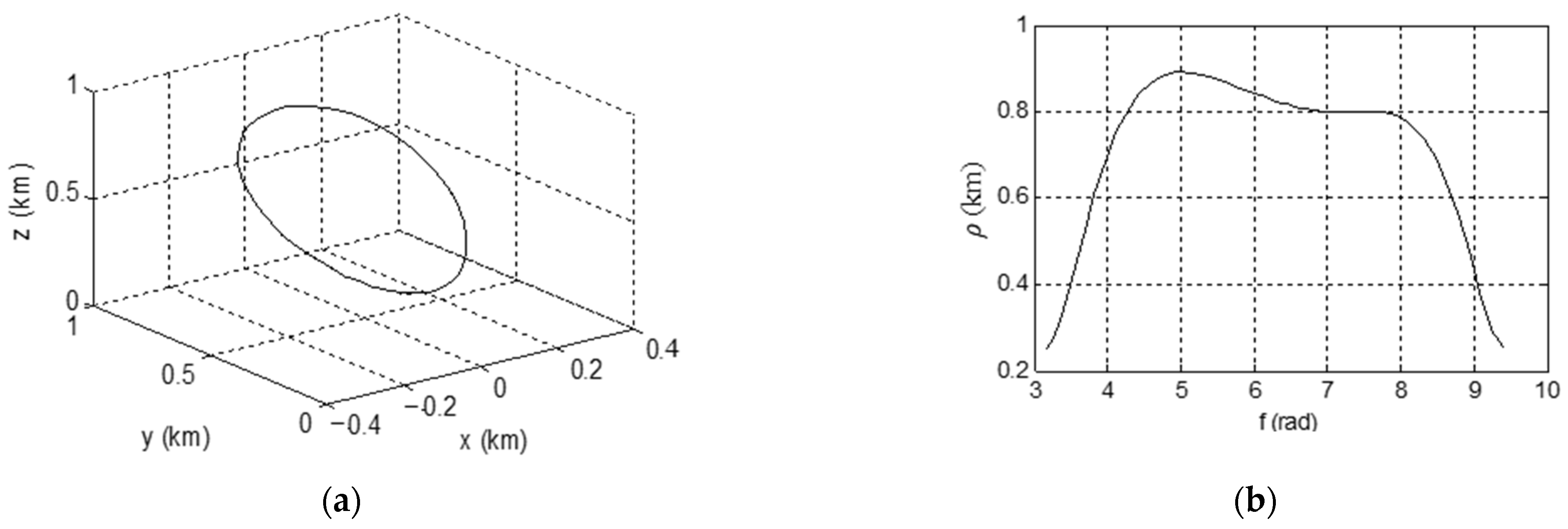
Again, consider a target spacecraft in an elliptical orbit with a s = 10,000 km and e = 0.3 . Assume that f = π ( f can be set on random); by solving Equation (6) and the equation in Equation (9), a set of initial values can be obtained easily, four groups of values are randomly selected as shown in Table 3, where the units of x1, x2, and x3 are in km, and the units of x4, x5, and x6 are in km/rad.
By randomly selecting the second group of values and plugging them into the left side of Equation (9), we have
Γ ( x ) = 5.933655687953914 × 10 8 < 0
then the initial distance between the two spacecrafts is the farthest. The simulations for relative motion are shown in Figure 2. Where f = π represents the initial position, at this time, the relative distance of the two spacecrafts is the furthest, as shown in Figure 2, which is consistent with the theoretical results.
By randomly selecting the fourth group of values and plugging them into the left side of Equation (9), we have
Γ ( x ) = 0.835806 > 0
then the initial distance between the two spacecrafts is the closest. The simulations for relative motion are shown in Figure 3. Where f = π represents the initial position, at this time, the relative distance of the two spacecrafts is the closest, as shown in Figure 3, which is consistent with the theoretical results.
As the basis of spacecraft formation flying, analysis of the spacecraft’s relative motion is very important. For the spacecraft relative motion model without any simplification, the problem of periodic relative motion was solved by energy-matching condition (i.e., mechanical energy is equal). And f was used as the independent variable in the analysis and calculation to make the calculation equation simple, which not only meets the accuracy requirements but also satisfies convenience for analysis.

4. Design and Control for Hovering Orbit

In order to enhance the safety and reliability of on-orbit service missions, the hovering orbit is a better choice to ensure that the mission spacecraft is stationary at a fixed point relative to the target spacecraft for a long time.
To realize the hovering state of the mission spacecraft relative to the target spacecraft, a continuous control force is required to ensure the stability of the state. Assuming that the target spacecraft travels in an elliptical orbit, based on the relative dynamics of the spacecraft, the high-precision hovering orbits, both without perturbation and considering J2 perturbation, are designed without any simplification are designed in this section. And corresponding simulations are carried out to test the performance of the method proposed.

4.1. Hovering Orbit without Perturbation

Assuming that the target spacecraft is traveling in an elliptical orbit, the relative dynamics equations can be written as
[ x ¨ y ¨ z ¨ ] + 2 [ n y ˙ n x ˙ 0 ] + [ n ˙ y n ˙ x 0 ] + [ n 2 x n 2 y 0 ] = μ g ( x , y , z ) [ r s + x y z ] + μ r s 2 [ 1 0 0 ] + [ a c x a c y a c z ]
where a c x , a c y and a c z are the control acceleration components of the mission spacecraft. Equation (11) is the set of high-precision relative dynamics equations without any simplification.
According to the characteristics of the hovering orbit, the mission spacecraft has the same angular velocity as the target spacecraft. To ensure the mission spacecraft hovers just below the target spacecraft, the necessary conditions can be described as
ρ = [ x y z ] = [ r c r s 0 0 ]
[ x ˙ y ˙ z ˙ ] = [ 0 0 0 ] ,   [ x ¨ y ¨ z ¨ ] = [ 0 0 0 ]
f c = f
Then, the relative dynamics equations of spacecraft can be simplified as
[ a c x a c y a c z ] = [ 0 n ˙ x 0 ] + [ n 2 x 0 0 ] + μ g ( x , y , z ) [ r s + x 0 0 ] μ r s 2 [ 1 0 0 ]
with the following relationship
r s = a s ( 1 e 2 ) 1 + e cos f
Then, the control acceleration required to maintain the hovering state of the mission spacecraft can be obtained:
a c x = μ ( 1 + e cos f ) 4 a s 3 ( 1 e 2 ) 3 ( r c a s ( 1 e 2 ) 1 + e cos f ) + μ r c 2 μ ( 1 + e cos f ) 2 a s 2 ( 1 e 2 ) 2 a c y = 2 μ e sin f a s 3 ( 1 e 2 ) 3 ( 1 + e cos f ) 3 ( r c a s ( 1 e 2 ) 1 + e cos f ) a c z = 0

4.2. Hovering Orbit with Considering J2 Perturbation

Assuming that the target spacecraft is traveling in an elliptical orbit, the relative dynamics equations of the spacecraft considering J2 perturbation can be written as
[ x ¨ y ¨ z ¨ ] + 2 [ n z y ˙ n z x ˙ n x z ˙ n x y ˙ ] + [ n z 2 x + n x n z z ( n x 2 + n z 2 ) y n x n z x n x 2 z ] + [ n ˙ z y n ˙ z x n ˙ x z n ˙ x y ] =                                     μ g ( x , y , z ) [ r s + x y z ] + μ r s 2 [ 1 0 0 ] + [ F c x F c y F c z ] [ F s x F s y F s z ] + [ a u c x a u c y a u c z ]
where
n = [ n x n y n z ] ,   n ˙ = [ n ˙ x n ˙ y n ˙ z ] ,   F c = [ F c x F c y F c z ] ,   F s = [ F s x F s y F s z ] ,   a u c = [ a u c x a u c y a u c z ]
F c and F s represent the acceleration of the mission spacecraft and the target spacecraft under J2 perturbation force, respectively; a u c is the control acceleration of the mission spacecraft. Equation (15) is also the set of high-precision relative dynamics equations without any simplification.
According to the characteristics of the hovering orbit, substituting the necessary condition which to ensure the mission spacecraft hovering just below the target spacecraft; that is, plugging Equation (12) into Equation (15) yields
[ n z 2 x 0 n x n z x ] + [ 0 n ˙ z x 0 ] = μ g ( x , y , z ) [ r s + x 0 0 ] + μ r s 2 [ 1 0 0 ] + [ F c x F c y F c z ] [ F s x F s y F s z ] + [ a u c x a u c y a u c z ]
According to the orbital mechanics theory, we have
F s = [ F s x = 3 μ R e 2 J 2 2 r s 4 ( 1 3 sin 2 i s sin 2 u s ) F s y = 3 μ R e 2 J 2 2 r s 4 sin 2 i s sin 2 u s F s z = 3 μ R e 2 J 2 2 r s 4 sin 2 i s sin u s ]
n = [ n x n y n z ] = [ Ω ˙ s sin u s sin i s + i ˙ s cos u s 0 Ω ˙ s cos i s + u ˙ s ]
{ Ω ˙ s = p s μ 1 sin i s sin u s 1 + e cos f f s z i ˙ s = p s μ cos u s 1 + e cos f f s z Ω ˙ s cos i s + u ˙ s = μ P s ( 1 + e cos f ) r s
where i is the orbit inclination, u denotes the argument of latitude, Ω is the right ascension of ascending node, J 2 is the second zonal harmonic coefficient of the Earth, R e represents Earth’s radius, and
R e = 6378.137   km ,   J 2 = 1.082636 × 10 3
Then, the components of n can be given as follows,
{ n x = 3 μ R e 2 J 2 2 r s 3 a s ( 1 e 2 ) sin 2 i s sin u s n y = 0 n z = μ a s ( 1 e 2 ) r s 2
and the components of n ˙ can be written as
{ n ˙ x = 9 μ J 2 2 R e 4 2 r s 6 a s ( 1 e 2 ) sin 2 u s sin 2 i s sin 2 i s sin u s  − 3 μ J 2 R e 2 2 r s 4 sin 2 i s ( cos u s r s 3 e sin f a s ( 1 e 2 ) sin u s ) n ˙ y = 0 n ˙ z = 3 μ R e 2 J 2 2 r s 5 sin 2 i s sin 2 u s 2 a s e ( 1 e 2 ) r s 3 sin f
According to the reference [33], the components of F c can be written as
F c x = S 11 F c x o + S 12 F c y o + S 13 F c z o F c y = S 21 F c x o + S 22 F c y o + S 23 F c z o F c z = S 31 F c x o + S 32 F c y o + S 33 F c z o
where
F c x o = 3 μ R e 2 J 2 2 r c 5 [ S 11 ( r s + x ) + S 21 y + S 31 z ] { 1 5 [ S 13 ( r s + x ) + S 23 y + S 33 z ] 2 r c 2 } F c y o = 3 μ R e 2 J 2 2 r c 5 [ S 12 ( r s + x ) + S 22 y + S 32 z ] { 1 5 [ S 13 ( r s + x ) + S 23 y + S 33 z ] 2 r c 2 } F c z o = 3 μ R e 2 J 2 2 r c 5 [ S 13 ( r s + x ) + S 23 y + S 33 z ] { 3 5 [ S 13 ( r s + x ) + S 23 y + S 33 z ] 2 r c 2 }
S = [ S 11 S 12 S 13 S 21 S 22 S 23 S 31 S 32 S 33 ]  = [ ( cos Ω s cos u s sin Ω s cos i s sin u s ) ( sin Ω s cos u s + cos Ω s cos i s sin u s ) sin i s sin u s ( cos Ω s sin u s sin Ω s cos i s cos u s ) ( sin Ω s sin u s + cos Ω s cos i s cos u s ) sin i s cos u s sin Ω s sin i s cos Ω s sin i s cos i s ]
Then, the control acceleration required to maintain the relative hovering state considering J2 perturbation can be obtained
a u c x = μ ( 1 + e cos f ) 4 a s 3 ( 1 e 2 ) 3 ( r c a s ( 1 e 2 ) 1 + e cos f ) + μ r c 2 μ ( 1 + e cos f ) 2 a s 2 ( 1 e 2 ) 2   + 3 μ R e 2 J 2 2 r c 4 ( 1 + 2 sin 2 i sin 2 u 5 sin i sin u )   − 3 μ R e 2 J 2 ( 1 + e cos f ) 4 2 a s 4 ( 1 e 2 ) 4 ( 1 3 sin 2 i s sin 2 u s ) a u c y = ( 3 μ R e 2 J 2 ( 1 + e cos f ) 5 2 a s 5 ( 1 e 2 ) 5 sin 2 i s sin 2 u s 2 ( 1 + e cos f ) 3 sin f a s 2 ( 1 e 2 ) 2 ) ( r c a s ( 1 e 2 ) 1 + e cos f )   + 3 μ R e 2 J 2 2 r c 4 ( sin 2 i sin 2 u ) 3 μ R e 2 J 2 ( 1 + e cos f ) 4 2 a s 4 ( 1 e 2 ) 4 sin 2 i s sin 2 u s a u c z = 3 μ R e 2 J 2 ( 1 + e cos f ) 5 2 a s 5 ( 1 e 2 ) 5 sin 2 i s sin u s ( r c a s ( 1 e 2 ) 1 + e cos f )   + 3 μ R e 2 J 2 2 r c 4 sin 2 i sin u 3 μ R e 2 J 2 ( 1 + e cos f ) 4 2 a s 4 ( 1 e 2 ) 4 sin 2 i s sin u s

4.3. Control for Hovering Orbit

The realization of the hovering of the spacecraft is actually a nonlinear control problem of relative motion. Some scholars have dealt with the control problem for relative motion, such as small satellite formation [14], a target spacecraft’s hovering [33], and so on.
The sliding mode control theory has gained broad attention and research because of its significant robustness. At present, the sliding mode control theory has been widely used in various fields [33,39,40,41,42,43].
The sliding mode control theory [44,45,46,47] can be introduced briefly as follows.
Consider the autonomous system represented by Equation (16)
x ˙ = f x , x R n
For control system Equation (16), there is a hypersurface S ( x ) in its state space, which divides the state space into two parts, i.e., S ( x ) > 0 and S ( x ) < 0. Therefore, the design problem needs to be solved by sliding mode control consisting of choosing the switching functions S ( x ) and the variable structure control u x such that the reaching modes satisfy the reaching conditions
u x = u + x , S ( x ) > 0 u x , S ( x ) < 0
where u + x u x . As x moves near the switching surface S x = 0 , we have
lim S 0 + S ˙ ( x ) 0 lim S 0 S ˙ ( x )
that is
l i m s ( x ) S ˙ S 0 ( x ) 0
Obviously, the above condition, which satisfies the stability of the Lyapunov function, is a sliding mode variable structure control. According to the stability condition, when x is in the region near S x = 0 and tends to S x = 0 , this region is called the sliding mode domain, and the motion of x in the region is called the sliding mode motion. Therefore, the sliding mode control can enable x to make the “sliding mode motion” along the desired state trajectory under certain characteristics, which can be designed in advance and is independent of the system parameters and disturbances.
Based on the derived model, Liang Zhang et al. [33] proposed open-loop control and closed-loop control, respectively; the simulation results prove that the accuracy of open-loop control where relative J2 perturbation has been significantly improved and demonstrates that the designed sliding mode controller, including the derived relative J2 perturbation, can guarantee the high accuracy and robustness of spacecraft hovering in a long-term mission. Based on the relative hovering model, the high-precision control method proposed in the literature [33] is adopted in this paper for hovering control, and the corresponding simulation and verification examples will be given in Section 4.4.

4.4. Simulation Examples and Performance Test

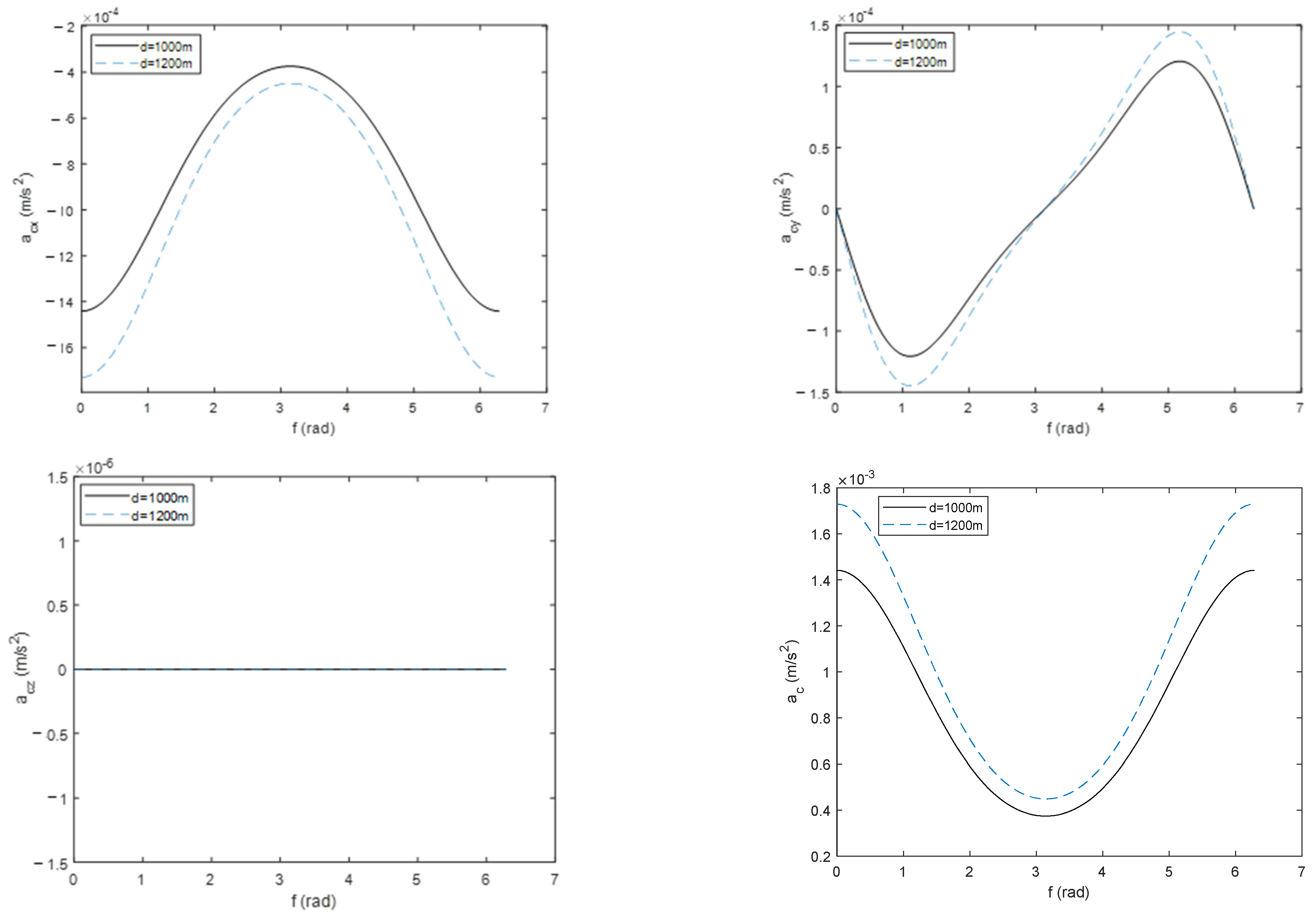
Selected orbital elements of the target spacecraft are shown in Table 4. Assuming that the mission spacecraft is required to hover just below the target spacecraft with the relative hovering distances, denoted as d , for different relative distances, the control accelerations without perturbation following the change of true anomaly during an orbital period are shown in Figure 4. Simulation results show that total acceleration reaches a minimum at apogee, and it increases with the increase of relative hovering distance.
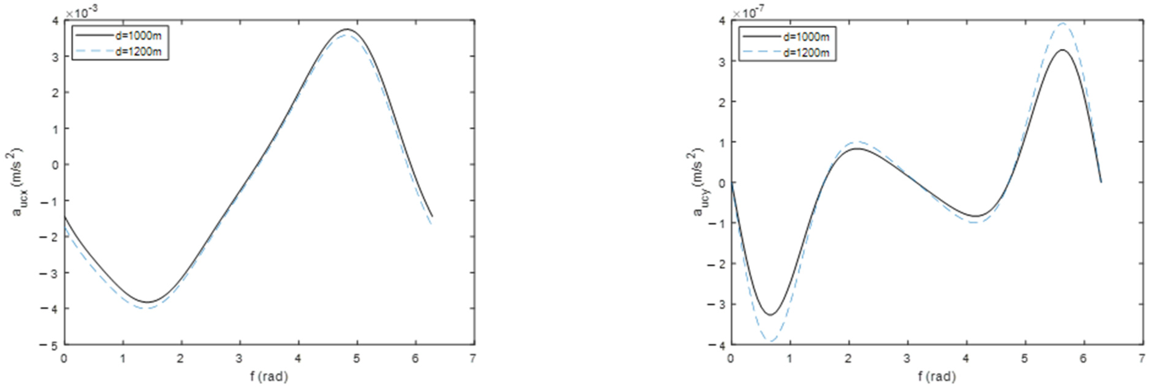
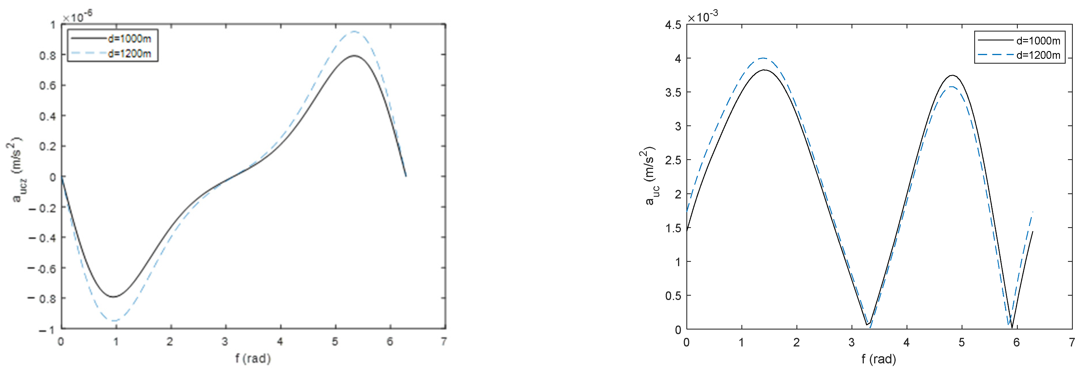
For different relative distances, the control accelerations considering J2 perturbation following the change of true anomaly during an orbital period are shown in Figure 5. When the mission spacecraft is hovering just below the target spacecraft with d = 1000   m , a comparison of total control accelerations between the cases without perturbation and with J2 perturbation is shown in Figure 6. It can be seen from the simulation results that J2 perturbation has a great influence on the hovering orbit.
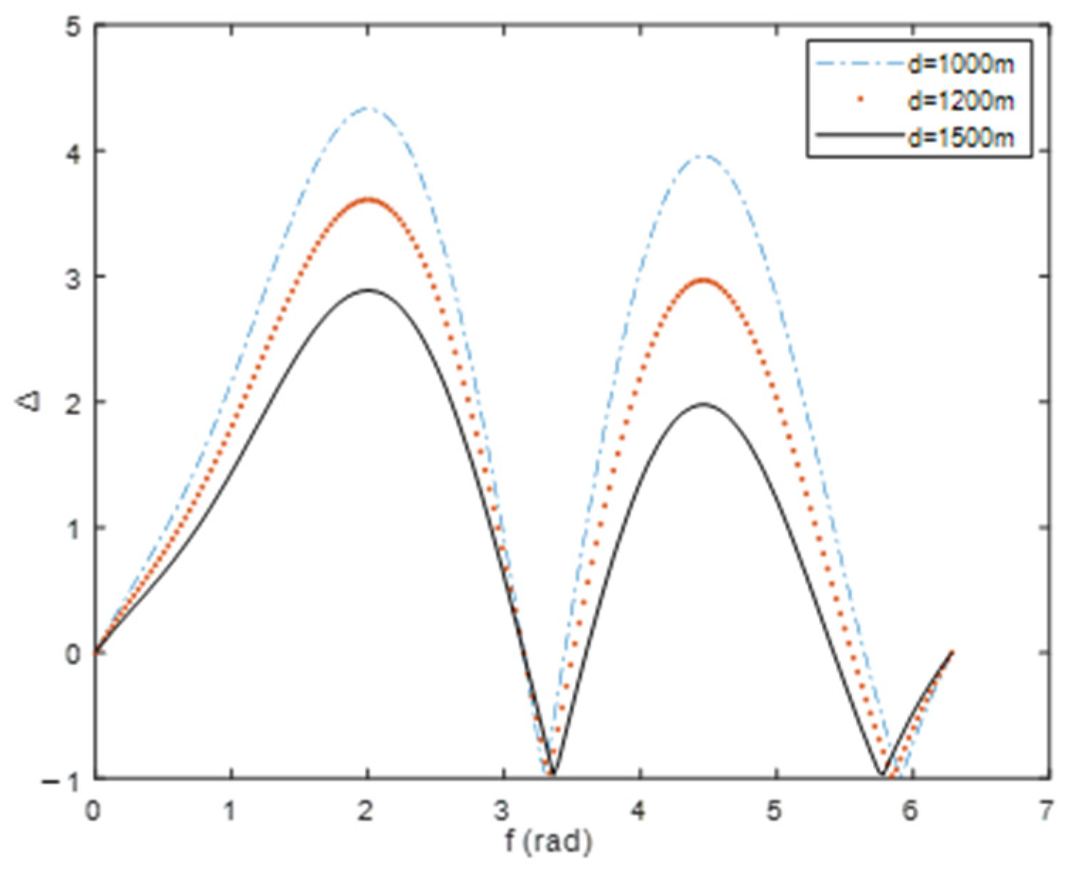
Define Δ as Δ = ( a u c a c ) / a c , which can be used to illustrate the effect of J2 perturbation on the required control acceleration to achieve the hovering orbit. For different relative distances, the corresponding Δ is shown in Figure 7, which shows that the difference of required total acceleration between the cases without perturbation and with J2 perturbation decreases gradually with the increase in relative hovering distance within a certain range.
Simulation results show that control acceleration curves are smooth, which indicates that the hovering flying mission is easier to achieve. The hovering orbit designed using the proposed method in the paper is shown in Figure 8.

5. Conclusions

The paper designs and simulates the hovering orbits both without perturbation and with J2 perturbation based on the spacecraft relative dynamics model. Firstly, based on the stability analysis of the spacecraft relative dynamics model, a method to determine the initial value of periodic relative motion orbit is explored and verified. The high-precision relative hovering dynamics models were put forward. Based on this, the formulae for control acceleration required to ensure the mission spacecraft hovering just below the target spacecraft were deduced. Then, the hovering orbit was simulated. Given the simulation results, some conclusive remarks are listed as follows:
(1)
The total control acceleration required to maintain the hovering state without considering perturbation increases with the increase of relative hovering distance and reaches a minimum at apogee;
(2)
J2 perturbation has a great influence on the hovering orbit. The difference in required total acceleration between the cases without perturbation and with J2 perturbation decreases gradually with the increase in relative hovering distance within a certain range;
(3)
The control acceleration curves are smooth enough to achieve hovering flying missions.
The method proposed in this paper can realize the relative hovering of the mission spacecraft relative to the target spacecraft with high precision, which is relatively easy to implement in engineering. It provides a means for dealing with perturbation in the design of hovering orbits.

Author Contributions

Conceptualization, X.L. and X.H.; Methodology, X.L., Z.L. and X.H.; Validation, X.L., L.Z. and X.H.; Formal analysis, X.L., L.Z. and Z.L.; Investigation, X.L., L.Z., Z.L. and X.H.; Data curation, X.L., L.Z., Z.L. and X.H.; Writing—original draft, X.L.; Writing—review & editing, X.L. and L.Z. All authors have read and agreed to the published version of the manuscript.

Funding

This research was funded by [Key technology research and development projects of Shaanxi Province] grant number [2023-YBGY-006] and [Natural Science Foundation of Shaanxi Province] grant number [S2021-JC-YB-0590].

Data Availability Statement

Not applicable.

Acknowledgments

The authors would like to thank Shaohui Li from Advanced Dynamics Incorporated for his valuable suggestions. The authors would also like to give their sincere thanks to the editors and anonymous reviewers.

Conflicts of Interest

The authors declare no conflict of interest.

References

  1. Li, W.-J.; Cheng, D.-Y.; Liu, X.-G.; Wang, Y.-B.; Shi, W.-H.; Tang, Z.-X.; Gao, F.; Zeng, F.-M.; Chai, H.-Y.; Luo, W.-B.; et al. On-orbit service (OOS) of spacecraft: A review of engineering developments. Prog. Aerosp. Sci. 2019, 108, 32–120. [Google Scholar] [CrossRef]
  2. Han, C.; Zhang, S.; Wang, X. On-orbit servicing of geosynchronous satellites based on low-thrust transfers considering perturbations. Acta Astronaut. 2019, 159, 658–675. [Google Scholar] [CrossRef]
  3. Flores-Abad, A.; Ma, O.; Pham, K.; Ulrich, S. A review of space robotics technologies for on-orbit servicing. Prog. Aerosp. Sci. 2014, 68, 1–26. [Google Scholar] [CrossRef] [Green Version]
  4. Koryanov, V.V.; Zhang, B. Research on Coplanar Orbit Maneuvering in the Context of on-Orbit Service. IOP Conf. Ser. Mater. Sci. Eng. 2019, 630, 012001. [Google Scholar] [CrossRef] [Green Version]
  5. Huang, X.; Yan, Y.; Huang, Z. Finite-time control of underactuated spacecraft hovering. Control Eng. Pract. 2017, 68, 46–62. [Google Scholar] [CrossRef]
  6. Ogundele, A.D. Modeling and analysis of nonlinear spacecraft relative motion via harmonic balance and Lyapunov function. Aerosp. Sci. Technol. 2020, 99, 105761. [Google Scholar] [CrossRef]
  7. Chao, J.; Zhaokui, W.; Yulin, Z. Decomposition analysis of spacecraft relative motion with different inter-satellite ranges. Acta Astronaut. 2019, 163, 56–68. [Google Scholar] [CrossRef]
  8. Ogundele, A.D.; Agboola, O.A. Nonlinear dynamic modeling of spacecraft relative motion in elliptical orbit via power series approach for rendezvous and proximity operations. Aerosp. Syst. 2021, 4, 281–300. [Google Scholar] [CrossRef]
  9. Ogundele, A.D.; Agboola, O.A.; Oseni, O.F. Nonlinear high-fidelity modeling of spacecraft relative motion via orbit element differences. Aerosp. Syst. 2022, 5, 591–605. [Google Scholar] [CrossRef]
  10. Shao, L.; Miao, H.; Hu, R.; Liu, H. Reachable set estimation for spacecraft relative motion based on bang-bang principle. Chin. J. Aeronaut. 2023, 36, 229–240. [Google Scholar] [CrossRef]
  11. Sun, H.; Li, J. Analysis on reachable set for spacecraft relative motion under low-thrust. Automatica 2020, 115, 108864. [Google Scholar] [CrossRef]
  12. Ogundele, A.D.; Agboola, O.A.; Sinha, S.C. Application of Lyapunov–Floquet transformation to the nonlinear spacecraft relative motion with periodic-coefficients. Acta Astronaut. 2021, 187, 24–35. [Google Scholar] [CrossRef]
  13. Vepa, R. Feedback tracking control of optimal reference trajectories for spacecraft relative motion. Adv. Space Res. 2022, 69, 3478–3489. [Google Scholar] [CrossRef]
  14. Popov, A.M.; Kostin, I.; Fadeeva, J.; Andrievsky, B. Development and Simulation of Motion Control System for Small Satellites Formation. Electronics 2021, 10, 3111. [Google Scholar] [CrossRef]
  15. Hai-Shuo, W.; Xi-Yun, H. Forced hovering orbit above the primary in the binary asteroid system. Celest. Mech. Dyn. Astron. 2022, 134, 50. [Google Scholar] [CrossRef]
  16. Gong, Y. Application of Celestial Mechanics Theory in Spacecraft Orbit Design. J. Phys. Conf. Ser. 2021, 1985, 012070. [Google Scholar] [CrossRef]
  17. D’Ambrosio, A.; Circi, C.; Zeng, X. Solar-photon sail hovering orbits about single and binary asteroids. Adv. Space Res. 2019, 63, 3691–3705. [Google Scholar] [CrossRef]
  18. Zhang, Y.; Zeng, X.; Zhang, F. Spacecraft Hovering Flight in a Binary Asteroid System by Using Fuzzy Logic Control. IEEE Trans. Aerosp. Electron. Syst. 2019, 55, 3246–3258. [Google Scholar] [CrossRef]
  19. Sawai, S.; Scheeres, D.J.; Broschart, S.B. Control of Hovering Spacecraft Using Altimetry. J. Guid. Control Dyn. 2002, 25, 786–795. [Google Scholar] [CrossRef]
  20. Lee, D.; Sanyal, A.K.; Butcher, E.A.; Scheeres, D.J. Almost global asymptotic tracking control for spacecraft body-fixed hovering over an asteroid. Aerosp. Sci. Technol. 2014, 38, 105–115. [Google Scholar] [CrossRef]
  21. Chen, J.; Du, C.; Zhang, Y.; Han, P.; Wei, W. A Clustering-Based Coverage Path Planning Method for Autonomous Heterogeneous UAVs. IEEE Trans. Intell. Transp. Syst. 2022, 23, 25546–25556. [Google Scholar] [CrossRef]
  22. Chen, J.; Zhang, Y.; Wu, L.; You, T.; Ning, X. An Adaptive Clustering-Based Algorithm for Automatic Path Planning of Heterogeneous UAVs. IEEE Trans. Intell. Transp. Syst. 2022, 23, 16842–16853. [Google Scholar] [CrossRef]
  23. Broschart, S.B.; Scheeres, D.J. Control of Hovering Spacecraft Near Small Bodies: Application to Asteroid 25143 Itokawa. J. Guid. Control Dyn. 2012, 28, 343–354. [Google Scholar] [CrossRef]
  24. Huang, X.; Yan, Y. Output Feedback Control of Underactuated Spacecraft Hovering in Circular Orbit With Radial or In-Track Controller Failure. IEEE Trans. Ind. Electron. 2016, 63, 5569–5581. [Google Scholar] [CrossRef]
  25. Wang, G.; Zheng, W.; Meng, Y.; Tang, G. Research on hovering control scheme to non-circular orbit. Sci. China Technol. Sci. 2011, 54, 2974–2980. [Google Scholar] [CrossRef]
  26. Zhang, J.; Zhao, S.; Yang, Y. Characteristic Analysis for Elliptical Orbit Hovering Based on Relative Dynamics. IEEE Trans. Aerosp. Electron. Syst. 2013, 49, 2742–2750. [Google Scholar] [CrossRef]
  27. Razoumny, Y.N. Locally Geostationary Orbits: Optimal Geometry of Elliptic Orbit for Earth Coverage. J. Spacecr. Rocket. 2019, 56, 1017–1023. [Google Scholar] [CrossRef]
  28. Bai, S.; Han, C.; Rao, Y.; Sun, X.; Sun, Y. New fly-around formations for an elliptical reference orbit. Acta Astronaut. 2020, 171, 335–351. [Google Scholar] [CrossRef]
  29. Wang, J.; Li, H.; Lin, Z.; Huo, H. Time-Fixed Glideslope Guidance for Approaching the Proximity of an Asteroid. Aerospace 2021, 8, 137. [Google Scholar] [CrossRef]
  30. Dang, Z.; Wang, Z.; Zhang, Y. Modeling and Analysis of Relative Hovering Control for Spacecraft. J. Guid. Control Dyn. 2014, 37, 1091–1102. [Google Scholar] [CrossRef]
  31. Bai, S.; Han, C.; Sun, X.; Zhang, H.; Jiang, Y. Teardrop hovering formation for elliptical orbit considering J2 perturbation. Aerosp. Sci. Technol. 2020, 106, 106098. [Google Scholar] [CrossRef]
  32. Zhang, L.; Ge, P. Trajectory Optimization and Orbit Design of Spacecraft in Hovering Mission. J. Astronaut. Sci. 2020, 67, 1344–1373. [Google Scholar] [CrossRef]
  33. Zhang, L.; Ge, P. High precision dynamic model and control considering J2 perturbation for spacecraft hovering in low orbit. Adv. Space Res. 2021, 67, 2185–2198. [Google Scholar] [CrossRef]
  34. Zhang, L.; Ge, P. Modeling and Control for Spacecraft Hovering Considering J2∼J4 Perturbation. J. Phys. Conf. Ser. 2021, 1746, 012001. [Google Scholar] [CrossRef]
  35. Zhu, G.; Lu, K.; Cao, Q.; Huang, P.; Zhang, K. Dynamic behavior analysis of tethered satellite system based on Floquet theory. Nonlinear Dyn. 2022, 109, 1379–1396. [Google Scholar] [CrossRef]
  36. Breda, D.; Liessi, D. Floquet Theory and Stability of Periodic Solutions of Renewal Equations. J. Dyn. Differ. Equ. 2021, 33, 677–714. [Google Scholar] [CrossRef]
  37. Friedmann, P.; Hammond, C.E.; Woo, T.-H. Efficient numerical treatment of periodic systems with application to stability problems. Int. J. Numer. Methods Eng. 1977, 11, 1117–1136. [Google Scholar] [CrossRef]
  38. Gurfil, P. Relative Motion between Elliptic Orbits: Generalized Boundedness Conditions and Optimal Formationkeeping. J. Guid. Control Dyn. 2005, 28, 761–767. [Google Scholar] [CrossRef]
  39. Jang, S.-H.; Yang, Y.; Leeghim, H. Angular Rate Constrained Sliding Mode Control of UAVs for Path Following. Electronics 2021, 10, 2776. [Google Scholar] [CrossRef]
  40. Sun, C.; Agha, S.A.; Mohamed, Z.; Shaheed, M.H. Optimised Sliding Mode Control of a Hexacopter: Simulation and Experiments. Electronics 2022, 11, 2519. [Google Scholar] [CrossRef]
  41. Xie, B.; Dai, S. Robust Terminal Sliding Mode Control on SE(3) for Gough–Stewart Flight Simulator Motion Platform with Payload Uncertainty. Electronics 2022, 11, 814. [Google Scholar] [CrossRef]
  42. Oh, K.; Seo, J. Development of a Sliding-Mode-Control-Based Path-Tracking Algorithm with Model-Free Adaptive Feedback Action for Autonomous Vehicles. Sensors 2022, 23, 405. [Google Scholar] [CrossRef]
  43. Balta, G.; Altin, N.; Nasiri, A. Interval Type-2 Fuzzy-Logic-Based Constant Switching Frequency Control of a Sliding-Mode-Controlled DC–DC Boost Converter. Appl. Sci. 2023, 13, 3239. [Google Scholar] [CrossRef]
  44. Utkin, V. Variable structure systems with sliding modes. IEEE Trans. Autom. Control 1977, 22, 212–222. [Google Scholar] [CrossRef]
  45. Hung, J.Y.; Gao, W.; Hung, J.C. Variable structure control: A survey. IEEE Trans. Ind. Electron. 1993, 40, 2–22. [Google Scholar] [CrossRef] [Green Version]
  46. Utkin, V.I. Sliding mode control design principles and applications to electric drives. IEEE Trans. Ind. Electron. 1993, 40, 23–36. [Google Scholar] [CrossRef] [Green Version]
  47. Young, K.D.; Utkin, V.I.; Ozguner, U. A control engineer’s guide to sliding mode control. IEEE Trans. Control Syst. Technol. 1999, 7, 328–342. [Google Scholar] [CrossRef] [Green Version]
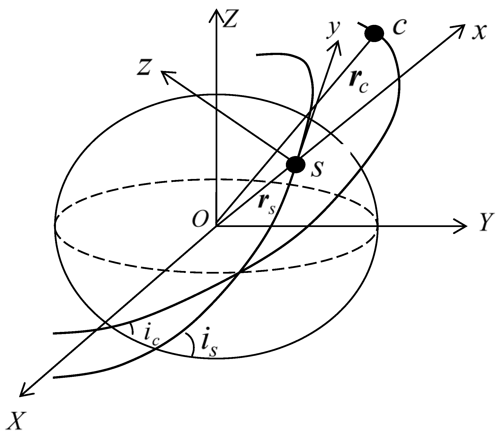
Figure 1. Coordinate systems.
Electronics 12 03034 g001
Figure 2. Relative motion 1. (a) Relative trajectory; (b) relative distance.
Electronics 12 03034 g002
Figure 3. Relative trajectory 2. (a) Relative trajectory; (b) relative distance.
Electronics 12 03034 g003
Figure 4. Control accelerations without perturbation for different relative distances.
Electronics 12 03034 g004
Figure 5. Control accelerations by considering J2 perturbation for different relative distances.
Electronics 12 03034 g005aElectronics 12 03034 g005b
Figure 6. Comparison of control accelerations.
Electronics 12 03034 g006
Figure 7. Corresponding Δ for different relative distances.
Electronics 12 03034 g007
Figure 8. Hovering orbit.
Electronics 12 03034 g008
Table 1. Floquet multipliers obtained by the Breda method.
λ 1 λ 2 λ 3 λ 4 λ 5 λ 6
1.0000 + 0.0000i1.0000 − 0.0000i1.0000 + 0.0000i1.0000 − 0.0000i1.00001.0000
Table 2. Floquet multipliers obtained by the Runge–Kutta method.
λ 1 λ 2 λ 3 λ 4 λ 5 λ 6
1.0064 + 0.0146i1.0064 − 0.0146i0.9936 + 0.0146i0.9936 − 0.0146i1.00001.0000
Table 3. Initial values for f = π .
x 1 x 2 x 3 x 4 x 5 x 6
1−6104.837312.26−3118.19−8652.17−5108.534959.66
2−22,414.5140.6361934.441606.636577.6418138
3−0.241799−0.2270480.2248480.3824690.5871691.00422
4−0.03129210.245415−0.0307399−0.2246760.07595630.835116
Table 4. Orbital elements.
Orbital ElementsThe Target Spacecraft
a / km 12,000
e 0.2
i / ° 30
ω / ° 0
f / ° 0
Disclaimer/Publisher’s Note: The statements, opinions and data contained in all publications are solely those of the individual author(s) and contributor(s) and not of MDPI and/or the editor(s). MDPI and/or the editor(s) disclaim responsibility for any injury to people or property resulting from any ideas, methods, instructions or products referred to in the content.