
A Low-RCS 2D Multi-Layer Van Atta Array at X-Band
National Key Laboratory of Antennas and Microwave Technology, Xidian University, Xi’an 710071, China
*
Author to whom correspondence should be addressed.
Electronics 2023, 12(16), 3486; https://doi.org/10.3390/electronics12163486
Submission received: 30 June 2023
/
Revised: 8 August 2023
/
Accepted: 14 August 2023
/
Published: 17 August 2023
(This article belongs to the Special Issue Applications of Array Antenna in Modern Wireless Systems)
Abstract
:This paper presents a novel approach to reducing radar cross section (RCS) using a 2D multi-layer Van Atta array based on the phase cancellation principle. By controlling the phase of transmission lines using wideband phase shifters, the proposed array can achieve significant RCS reduction at a wide frequency range of 8 GHz to 11 GHz. Both theoretical calculations and experimental measurements were conducted to evaluate the performance of the Van Atta array with phase shifters. Results showed significant RCS reduction from various incident angles, demonstrating the effectiveness of the proposed design in achieving wideband RCS reduction at the X-band.
1. Introduction
Radar cross section (RCS) reduction of antennas has attracted much attention in recent years and has found wide application in different fields, especially in stealth technology such as fighter planes. Considerable research interest in radar cross section reduction has been triggered by the development of modern stealth technology. The methods of using radar-absorbing materials and phase cancellation screens are studied. Absorbing materials could realize RCS reduction and are applied to some applications due to their advantages of being flexible and convenient, such as microwave absorbing materials (MAMs) [1,2,3] and high impendence surfaces (HISs) [4,5]. However, their effectiveness is limited by narrow bandwidth, frequency, and incident angle dependence. Distinct from the approach of using absorbing materials to absorb electromagnetic waves, another method of achieving RCS reduction is by using phase cancellation theory to redirect or cancel the incident wave by modifying the characteristics of the reflected wave, such as frequency-selective surfaces (FSSs), artificial magnetic conductors (AMCs), and polarization rotation reflective surfaces (PRRSs). They can achieve wideband RCS reduction and high reduction rates [6]. An FSS is a periodic surface with identical 2D arrays of elements arranged on a dielectric substrate, exhibiting transmission and reflection at certain resonant frequencies [7,8,9,10]. As for AMC, the RCS reduction is realized with the combination of AMC units and perfect electronic conductors [11,12,13,14]. PRRS could reflect the incoming wave with a 90° polarization rotation to realize RCS reduction [15,16]. Recently, a low-wideband RCS antenna co-designed with a high-performance AMC-FSS radome has been formed, and the monostatic RCS for a normal incidence is greatly reduced from 4–18 GHz [17]. However, these methods mentioned above generally need a large space, and the RCS reduction rate of these methods is rapidly decreased depending on the angle of the incident wave.
Addressing these challenges, a method was developed to obtain angular independence in RCS reduction by adjusting the length of transmission lines in the Van Atta array. The RCS of this structure is reduced at the angle of incidence by making a null [18]. The simulation result indicated that the Van Atta array exhibited a lower RCS level than the identical-sized metal plate. Reference [19] used the adjustable transmission line switch from 0 to phase to add phase modulation of the retro-reflected signal, and the results show the Van Atta array can realize phase modulation in a large range of the incident angle. However, it is important to note that the RCS reduction achieved through this method is limited to a narrow frequency band due to the variations in the phase of the same-length transmission lines at different frequencies.
This paper discusses a low-RCS 2D multi-layer Van Atta array based on a microstrip antenna operating at X-band. The array’s construction is shown in Figure 1; the line connection pattern of the array is shown in Figure 1a, and the side view of the array is shown in Figure 1b. The antennas on the top layer with each unit are connected to the feeding network on the bottom layer by the probe, and the ground plane is between the top layer and the bottom layer. Wideband RCS reduction could be realized by using wideband phase shifters to adjust the phase of the feeding network. Table 1 shows the comparison of different RCS reduction methods, indicating that our proposed array performs well in both bandwidth and angle independence compared to other RCS reduction methods.
2. Theory and Design
The Van Atta array is a retrodirective array composed of a pair of antennas connected by equal-length transmission lines and symmetrically located around the array center. As shown in Figure 2, it can reverse the electromagnetic wave incident from an unknown angle. Generally, because of the retrodirective characteristic, the Van Atta array can maintain a relatively larger RCS over a large range of incidence angles [20,21].
According to the principles of phase cancellation theory, two signals that possess equal amplitude but are in phase amplify each other, while signals that are out of phase by 180° could cancel each other out [22]. Therefore, adding a 180° phase shift to half of the Van Atta array transmission lines can achieve significant phase cancellation [18]. To reduce RCS, four transmission lines out of eight were selected to add a 180° phase shift, resulting in 35 different combinations. In this paper, the selected feeding method is shown in Table 2.
The theoretical calculation result for phase cancellation of Table 2 combination at 10 GHz is shown in Figure 3, which shows that this method can realize phase cancellation, leading to a significant reduction in the reflected wave at the incident angle. The RCS reduction can achieve more than 40 dB.
Conventionally, the Van Atta array reduces the RCS level by changing the length of transmission lines, which is only effective in narrowband. To achieve wideband RCS reduction, the Van Atta array element must be wideband, and the transmission line needs to realize a 180° phase shift across the wide frequency range. This paper employs a wideband U-slot antenna as the array element and utilizes wideband phase shifters to control the phase of transmission lines. This enables effective RCS reduction across a broad frequency range. The phase shifter structure and the phase difference are shown in Figure 4. Apparently, the phase shifter is able to achieve a phase shift of 180° ± 10° over 8 to 11 GHz.
The construction of the transmission lines as the feeding network of the low-RCS Van Atta array was designed. Based on Table 2, four phase shifters were used on eight transmission lines. The phase differences between line1 and other transmission lines are shown in Figure 5a,b, indicating that all phase differences are kept within the range of ±10°. In Figure 5c, variations in RCS reduction with different phases are presented, which indicates that the RCS reduction of 180° is more than 25 dB from 8 GHz to 11 GHz, whereas it is less than 18 dB when the phase deviates 10° from 180° (i.e., 170° and 190°).
In this paper, a U-slot wideband microstrip antenna unit is designed to form a 16-element array. The configuration of the antenna unit and the VSWR of the antenna are shown in Figure 6, which demonstrates that the antenna could work in the frequency band from 8 GHz to 11 GHz.
Two types of 16-element Van Atta arrays were manufactured, including a regular retrodirective multi-layer array named Array1 and a low-RCS multi-layer array named Array2. The structure of the top layer is identical for both arrays, as shown in Figure 7a. The size of the top layer is 135 mm × 115 mm × 3 mm (). The bottom layer of Array1 as the feeding network consists of eight transmission lines of the same length, whereas the bottom layer of Array2 consists of eight equal-length transmission lines with four wideband phase shifters whose phase shift is 180° ± 10° over the band of 8–11 GHz. The bottom layers of Array1 and Array2, as shown in Figure 7a,b, have the same total dimension of 135 mm × 115 mm × 0.6 mm (). The top and bottom layers of both Array1 and Array2 are integrated using metal vias.
3. Measurement Setup and Results
Figure 8 illustrates the setup used for monostatic RCS measurement. It consists of two horn antennas and a turntable. One of the horn antennas functions as the transmitter, and the other operates as the receiver, both connected to a vector network analyzer (VNA). These two horn antennas are placed side by side and directly point at the proposed antenna array. To ensure a plane wave incidence, the distance between the antenna array and horn antennas is set to be greater than , where D represents the maximum dimension of the antenna array, and denotes the wavelength. As the turntable rotates, the incident angle changes accordingly. When the top layer of the antenna array is aligned with the horn antennas, the incident angle is set to 0°.
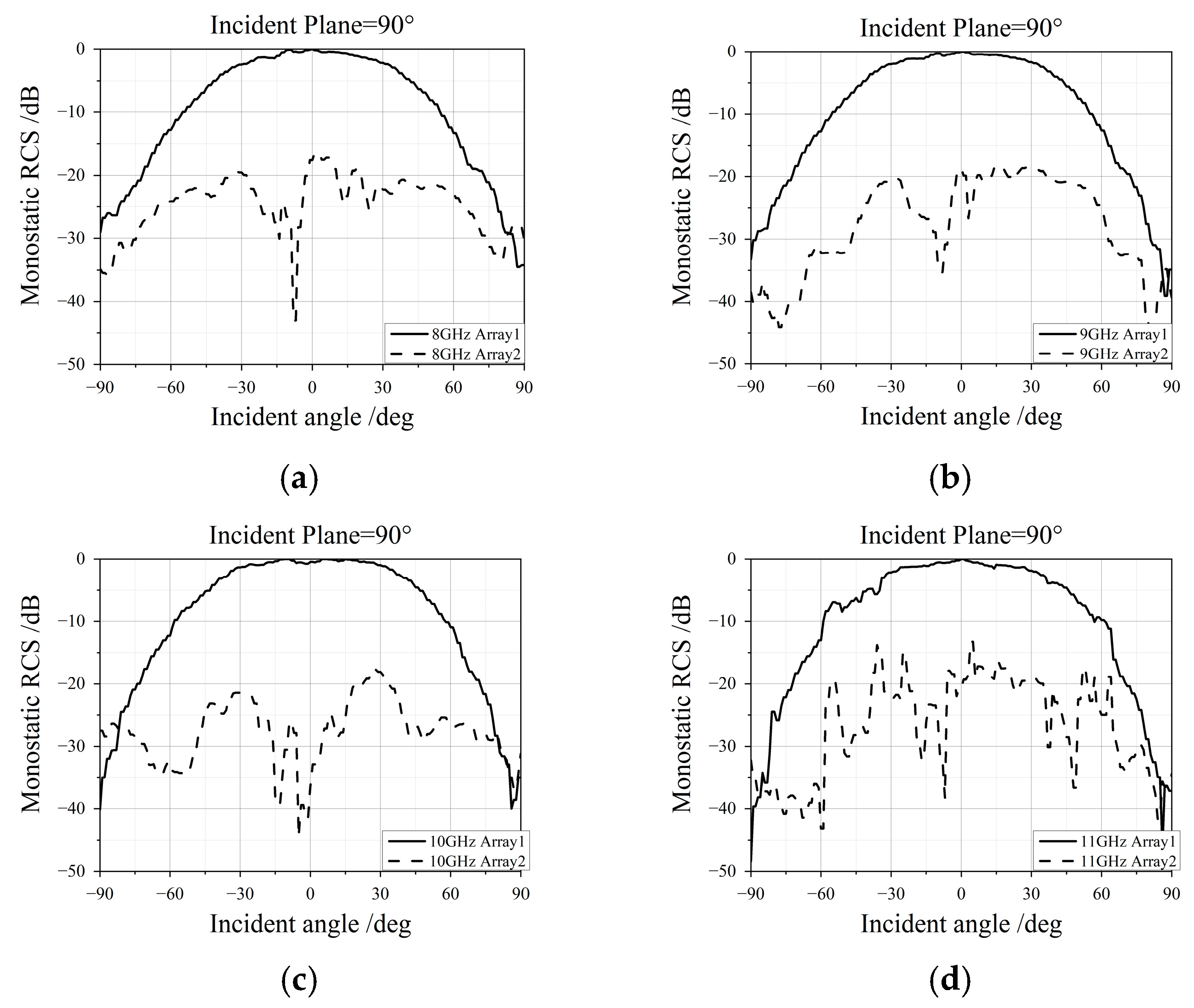
Comparing the retrodirective antenna array (Array1) with the low-RCS antenna array (Array2), we conducted monostatic RCS measurements in an anechoic chamber. The measurement results of the arrays are presented in Figure 9 and Figure 10, showing the RCS reduction at different incident planes of 0° and 90°. The monostatic RCS of the retrodirective antenna array (Array1) is higher than that of the Van Atta array with phase shifters (Array2). Specifically, the RCS level of Array2 is approximately 20 dB lower than that of Array1 at an initial angle of 8 GHz to 11 GHz. These results demonstrate the effectiveness of the proposed Van Atta array in achieving RCS reduction across a wide frequency range.
As shown in Figure 9 and Figure 10, the performance of the incident plane at 90° surpasses that of the incident plane at 0°. This discrepancy can mainly be attributed to the non-symmetrical construction of the U-slot antenna unit. Notably, at the frequency of 11 GHz, the RCS reduction results are less significant compared to other frequencies due to the increased phase deviations among transmission lines.
4. Conclusions
In this study, we designed a 2D multi-layer Van Atta array with phase shifters to reduce monostatic RCS effectively. By controlling the phase of transmission lines, the proposed array achieved phase cancellation across a wide frequency range, resulting in a significant RCS reduction. Both simulation and experimental results demonstrated that the Van Atta array with phase shifters effectively reduced RCS from 8 GHz to 11 GHz at various angles of incidence. Overall, the proposed approach presents a promising solution for designing low-RCS antennas for radar and communication systems.
Author Contributions
Conceptualization, L.C.; methodology, L.C. and M.Q.; software, L.C.; validation, M.Q.; formal analysis, L.Z. and T.Z.; investigation, T.Z.; resources, L.C.; data curation, L.C.; writing—original draft preparation, L.C. and M.Q.; writing—review and editing, L.C., L.Z. and T.Z. All authors have read and agreed to the published version of the manuscript.
Funding
The work is supported by the Hongque Innovation Center (HQ202205002).
Institutional Review Board Statement
Not applicable.
Informed Consent Statement
Not applicable.
Data Availability Statement
The data presented in this study are available on request from the corresponding author.
Conflicts of Interest
The authors declare no conflict of interest.
References
- El-Hakim, H.A.; Mahmoud, K.R. A Comparative Study between Different Approaches to Improve the RCS of a Compact Double-Layer Absorber. J. Inst. 2017, 12, P10022. [Google Scholar] [CrossRef]
- Gong, Y.-X.; Zhou, Z.-X.; Jiang, J.-T.; Zhao, H.-J. Design of Ultra Wideband Microwave Absorber Effectual for Objects of Arbitrary Shape. Chin. Phys. B 2015, 24, 124101. [Google Scholar] [CrossRef]
- Venneri, F.; Costanzo, S.; Borgia, A. A Dual-Band Compact Metamaterial Absorber with Fractal Geometry. Electronics 2019, 8, 879. [Google Scholar] [CrossRef]
- Libimol, V.A.; Aanandan, C.K. Checker Board HIS with Defected Ground Structure for Positive Reflection Phase Gradient and Wideband RCS Reduction. In Proceedings of the 2016 International Conference on Next Generation Intelligent Systems (ICNGIS), Kottayam, India, 1–3 September 2016; pp. 1–3. [Google Scholar]
- Sievenpiper, D.; Zhang, L.; Broas, R.F.J.; Alexopolous, N.G.; Yablonovitch, E. High-Impedance Electromagnetic Surfaces with a Forbidden Frequency Band. IEEE Trans. Microw. Theory Tech. 1999, 47, 2059–2074. [Google Scholar] [CrossRef]
- Zaker, R.; Sadeghzadeh, A. Passive Techniques for Target Radar Cross Section Reduction: A Comprehensive Review. Int. J. RF Microw. Comput.-Aided Eng. 2020, 30, e22411. [Google Scholar] [CrossRef]
- Wang, F.; Li, K.; Ren, Y.; Zhang, Y. A Novel Reconfigurable FSS Applied to the Antenna Radar Cross Section Reduction. Int. J. RF Microw. Comput.-Aided Eng. 2019, 29, e21729. [Google Scholar] [CrossRef]
- Nourinia, J.; Ghobadi, C.; Mohammadi, B.; Mahmoud, A.; Aryanian, I. RCS Reduction of Reflectarray Antenna Backed with Sub-Wavelength Frequency Selective Surface. In Proceedings of the 2019 27th Iranian Conference on Electrical Engineering (ICEE), Yazd, Iran, 30 April 2019–2 May 2019; pp. 1627–1631. [Google Scholar]
- Zainud-Deen, S.H.; Malhat, H.A.E.-A.; Shabayek, N.A. Reconfigurable RCS Reduction from Curved Structures Using Plasma Based FSS. Plasmonics 2020, 15, 341–350. [Google Scholar] [CrossRef]
- Anwar, R.S.; Mao, L.; Ning, H. Frequency Selective Surfaces: A Review. Appl. Sci. 2018, 8, 1689. [Google Scholar] [CrossRef]
- Paquay, M.; Iriarte, J.-C.; Ederra, I.; Gonzalo, R.; de Maagt, P. Thin AMC Structure for Radar Cross-Section Reduction. IEEE Trans. Antennas Propag. 2007, 55, 3630–3638. [Google Scholar] [CrossRef]
- Zheng, W.-B.; Song, W.; Sheng, X.-Q. A Broadband AMC-Based Reflector for RCS Reduction. In Proceedings of the 2017 International Applied Computational Electromagnetics Society Symposium (ACES), Suzhou, China, 1–4 August 2017; pp. 1–2. [Google Scholar]
- Xue, J.; Jiang, W.; Gong, S. Chessboard AMC Surface Based on Quasi-Fractal Structure for Wideband RCS Reduction. IEEE Antennas Wirel. Propag. Lett. 2018, 17, 201–204. [Google Scholar] [CrossRef]
- Sang, D.; Chen, Q.; Ding, L.; Guo, M.; Fu, Y. Design of Checkerboard AMC Structure for Wideband RCS Reduction. IEEE Trans. Antennas Propag. 2019, 67, 2604–2612. [Google Scholar] [CrossRef]
- Zaker, R.; Sadeghzadeh, A. A Low-Profile Design of Polarization Rotation Reflective Surface for Wideband RCS Reduction. IEEE Antennas Wirel. Propag. Lett. 2019, 18, 1794–1798. [Google Scholar] [CrossRef]
- Lu, Y.; Su, J.; Liu, J.; Guo, Q.; Yin, H.; Li, Z.; Song, J. Ultrawideband Monostatic and Bistatic RCS Reductions for Both Copolarization and Cross Polarization Based on Polarization Conversion and Destructive Interference. IEEE Trans. Antennas Propag. 2019, 67, 4936–4941. [Google Scholar] [CrossRef]
- Xing, Z.; Yang, F.; Yang, P.; Yang, J. A Low-RCS and Wideband Circularly Polarized Array Antenna Co-Designed with a High-Performance AMC-FSS Radome. IEEE Antennas Wirel. Propag. Lett. 2022, 21, 1659–1663. [Google Scholar] [CrossRef]
- Kim, Y.; Lee, W.; Yoon, Y.J. Mono-Static RCS Reduction Using Modified van Atta Array. In Proceedings of the 2013 IEEE Antennas and Propagation Society International Symposium (APSURSI), Orlando, FL, USA, 7–13 July 2013; pp. 1222–1223. [Google Scholar]
- Song, K.; Feng, D.; Wang, J.; Xie, Q.; Liu, L. Phase Modulation of Retro-Reflected Radar Echo Signal Using a Microstrip Van-Atta Array. IEEE Access 2019, 7, 96011–96018. [Google Scholar] [CrossRef]
- Yau, K.S.B. Planar Multi-Layer Passive Retrodirective Van Atta Array Reflectors at X-Band. In Proceedings of the 2015 International Symposium on Antennas and Propagation (ISAP), Hobart, TAS, Australia, 9–12 November 2015; pp. 1–4. [Google Scholar]
- Farzami, F.; Khaledian, S.; Smida, B.; Erricolo, D. Erricolo Reconfigurable Dual-Band Bidirectional Reflection Amplifier with Applications in Van Atta Array. IEEE Trans. Microw. Theory Tech. 2017, 65, 4198–4207. [Google Scholar] [CrossRef]
- Fujita, M.; Murakami, C. Experimental Study of a Polarization-Rotating Van Atta Array with Reduced Co-Polarized Radar Cross-Section. In Proceedings of the IGARSS 2003, 2003 IEEE International Geoscience and Remote Sensing Symposium, Proceedings (IEEE Cat. No.03CH37477), Toulouse, France, 21–25 July 2003; Volume 7, pp. 4503–4505. [Google Scholar]
Figure 1.
A 2D multi-layer Van Atta Array: (a) line connection pattern of the array; (b) side view of the array.
Figure 1.
A 2D multi-layer Van Atta Array: (a) line connection pattern of the array; (b) side view of the array.
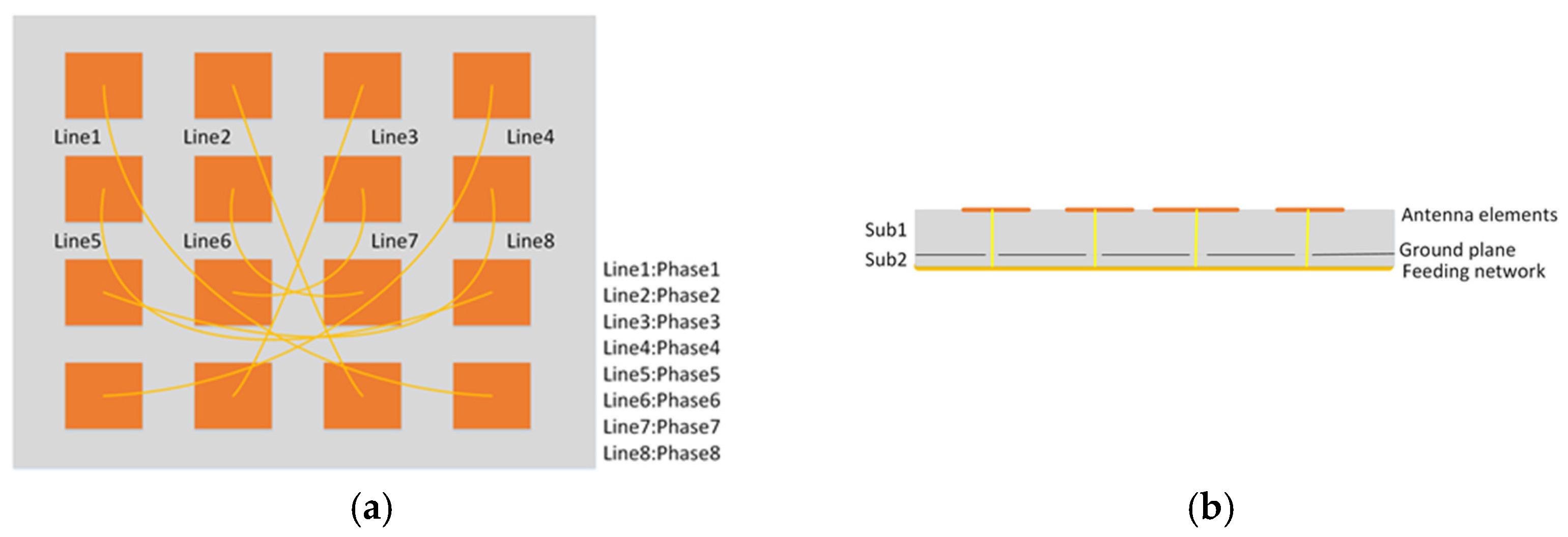
Figure 2.
Van Atta array function.

Figure 3.
Phase cancellation of the array.
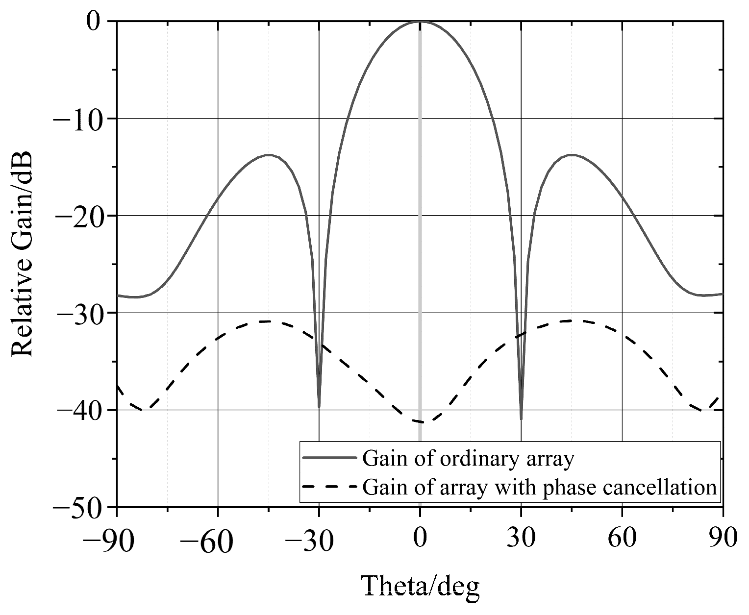
Figure 4.
Wideband phase shifter and the phase difference.

Figure 5.
Phase difference between transmission lines and its impact on RCS reduction. (a) Phase difference between line1 and line2, line5, and line7; (b) phase difference between line1 and line2, line4, line6, and line8; (c) RCS reduction with different phases.
Figure 5.
Phase difference between transmission lines and its impact on RCS reduction. (a) Phase difference between line1 and line2, line5, and line7; (b) phase difference between line1 and line2, line4, line6, and line8; (c) RCS reduction with different phases.

Figure 6.
Antenna unit and VSWR.

Figure 7.
Photos of fabricated antenna arrays: (a) top layer of the arrays; (b) bottom layer of Array1; (c) bottom layer of Array2.
Figure 7.
Photos of fabricated antenna arrays: (a) top layer of the arrays; (b) bottom layer of Array1; (c) bottom layer of Array2.

Figure 8.
Monostatic RCS setup.
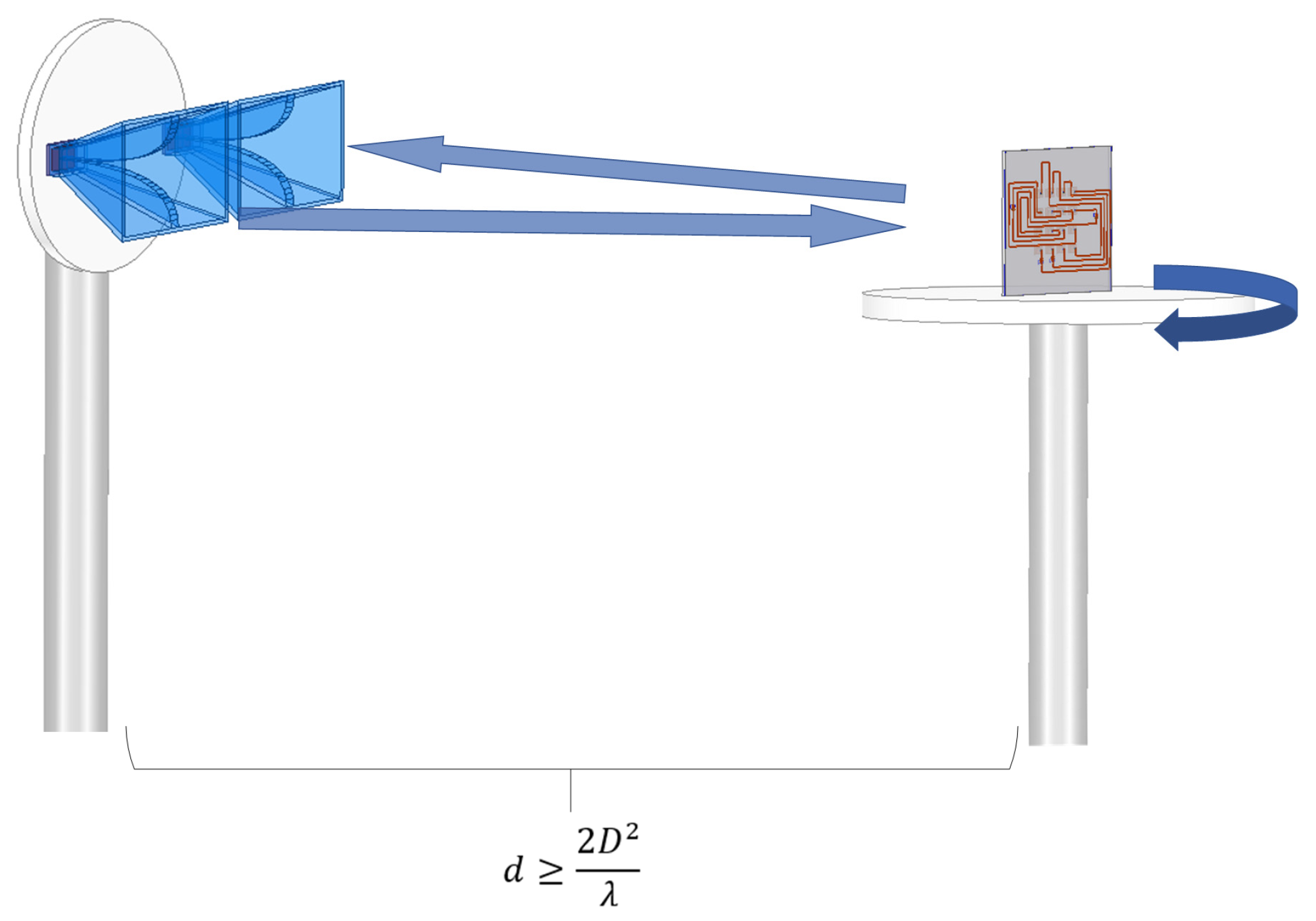
Figure 9.
Monostatic RCS of Array1 and Array2 from 8 GHz to 11 GHz (incident plane = 0°): (a) 8 GHz; (b) 9 GHz; (c) 10 GHz; (d) 11 GHz.
Figure 9.
Monostatic RCS of Array1 and Array2 from 8 GHz to 11 GHz (incident plane = 0°): (a) 8 GHz; (b) 9 GHz; (c) 10 GHz; (d) 11 GHz.

Figure 10.
Monostatic RCS of Array1 and Array2 from 8 GHz to 11 GHz (incident plane = 90°): (a) 8 GHz; (b) 9 GHz; (c) 10 GHz; (d) 11 GHz.
Figure 10.
Monostatic RCS of Array1 and Array2 from 8 GHz to 11 GHz (incident plane = 90°): (a) 8 GHz; (b) 9 GHz; (c) 10 GHz; (d) 11 GHz.

Table 1.
Comparison of different RCS reduction methods.
| Methods | Ref. | Frequency (GHz) | RCS Reduction Level | Incident Angles | Bandwidth | Angle Independence |
|---|---|---|---|---|---|---|
| absorbing material | [2] | 2–18 | −10 dB | ±30° | wideband | no |
| [3] | 0.878 and 0.965 | −25 dB | not mentioned | narrowband | no | |
| FSS, AMC, and PRRS | [11] | 15–15.4 | −20 dB | ±15° | narrowband | no |
| [13] | 5.4–14.2 | −10 dB | ±10° | wideband | no | |
| [14] | 3.77–10.14 | −10 dB | ±20° | wideband | no | |
| [16] | 7.5–22.5 | −10 dB | ±30° | wideband | no | |
| [17] | 4–18 GHz | −13.7 dB | ±25° | wideband | no | |
| Van Atta array | [18] | not mentioned | −25 dB | over ± 40° | narrowband | yes |
| [19] | 9.75–10.75 | not mentioned | large range angle | narrowband | yes | |
| proposed array | - | 8–11 | −20 dB | maximum ± 90° | wideband | yes |
Table 2.
Transmission line phase selection.
| Transmission Lines Number | Phase [deg] |
|---|---|
| line1 | 180 |
| line2 | 180 |
| line3 | 0 |
| line4 | 0 |
| line5 | 180 |
| line6 | 0 |
| line7 | 180 |
| line8 | 0 |
Disclaimer/Publisher’s Note: The statements, opinions and data contained in all publications are solely those of the individual author(s) and contributor(s) and not of MDPI and/or the editor(s). MDPI and/or the editor(s) disclaim responsibility for any injury to people or property resulting from any ideas, methods, instructions or products referred to in the content. |
© 2023 by the authors. Licensee MDPI, Basel, Switzerland. This article is an open access article distributed under the terms and conditions of the Creative Commons Attribution (CC BY) license (https://creativecommons.org/licenses/by/4.0/).
Share and Cite
MDPI and ACS Style
Chen, L.; Qin, M.; Zou, L.; Zhang, T. A Low-RCS 2D Multi-Layer Van Atta Array at X-Band. Electronics 2023, 12, 3486. https://doi.org/10.3390/electronics12163486
AMA Style
Chen L, Qin M, Zou L, Zhang T. A Low-RCS 2D Multi-Layer Van Atta Array at X-Band. Electronics. 2023; 12(16):3486. https://doi.org/10.3390/electronics12163486
Chicago/Turabian StyleChen, Lei, Mingjuan Qin, Lin Zou, and Tianling Zhang. 2023. "A Low-RCS 2D Multi-Layer Van Atta Array at X-Band" Electronics 12, no. 16: 3486. https://doi.org/10.3390/electronics12163486
Note that from the first issue of 2016, this journal uses article numbers instead of page numbers. See further details here.