
A Novel Unit Classification Method for Fast and Accurate Calculation of Radiation Patterns

1
Nanjing Research Institute of Electronics Technology, Nanjing 210039, China
2
The National Key Laboratory of Antennas and Microwave Technology, Xidian University, Xi’an 710071, China
*
Author to whom correspondence should be addressed.
Electronics 2023, 12(16), 3512; https://doi.org/10.3390/electronics12163512
Submission received: 24 July 2023
/
Revised: 16 August 2023
/
Accepted: 18 August 2023
/
Published: 19 August 2023
(This article belongs to the Special Issue Antenna Design and Its Applications)
Abstract
:This paper proposes a novel unit classification technique to enhance the accuracy of the conventional pattern multiplication method by taking the mutual coupling effect and edge effect into consideration. The proposed technique classifies antenna elements into different groups based on their positions in arrays, specifically corner, edge, and inner groups. By simulating the radiation patterns of antenna elements with different boundary conditions, the pattern multiplication method is then used to calculate the radiation pattern of the antenna array based on the simulated results. Several numerical examples, including a square array, a hexagonal array, and a phased array, are provided to validate the effectiveness of the proposed method. The numerical results demonstrate that the proposed method not only reduces the computational time and memory usage but also significantly improves the accuracy. The proposed method provides a powerful tool for synthesizing and predicting the radiation pattern of array antennas and offers new avenues for optimizing array antennas and phased array antennas.
1. Introduction
Array antennas have gained significant popularity in various modern radio systems, such as radar and communication systems [1,2,3,4,5]. These systems often require antenna arrays with high directivity, low sidelobe levels, and wide-angle scanning capabilities [6,7]. Thus, optimizing the design of array antennas is important work in modern electronics system design [8]. Array antennas consist of multiple elements arranged in specific configurations [9,10]. By varying the number of elements, their arrangement, or excitation, the radiation patterns of various arrays can be generated [11,12].
Currently, full-wave simulation software, including CST, HFSS, and FEKO, is widely used for calculating the radiation pattern of array antennas [13,14]. However, for large-scale array antennas, full-wave simulation can be time-consuming and computationally intensive. The pattern multiplication method [15,16,17], which will be discussed in detail in Section 2, offers a simple and efficient approach to calculating the radiation pattern of an array antenna. Using this method, the radiation pattern of an array is calculated with the product of the array factor and the element radiation pattern. However, the traditional pattern multiplication method assumes that the radiation pattern of each antenna element is unitary. In reality, mutual coupling and edge effects between the antenna elements in an array introduce deviations from unity element radiation characteristics, leading to errors when using the traditional multiplication method [18,19,20]. Therefore, improving the pattern multiplication method by considering the mutual coupling effect and edge effect is necessary. The active element pattern (AEP) method has been introduced to address this issue [21,22,23]. The AEP has found applications in the synthesis of conformal phased arrays [24] and the estimation of the antenna mode radar cross-section (AM-RCS) [25]. In addition to the pattern multiplication method, researchers have proposed other effective methods for calculating the radiation pattern of array antennas and phased array antennas. For instance, the conjugate gradient method has been used to achieve pattern synthesis for array antennas with arbitrary geometry [26]. In recent years, artificial intelligence techniques have been employed in the synthesis of array antenna radiation patterns [27,28].
In this study, a new method called the unit classification method is proposed based on the traditional pattern multiplication method. This method incorporates the mutual coupling effect and the edge effect to calculate the far-field radiation pattern. Furthermore, it retains the advantages of the pattern multiplication method, including fast computation speed and low memory consumption. Several numerical examples, including a square array with patch antennas, a hexagonal array with patch antennas, and a phased array, are discussed to validate the effectiveness and versatility of the proposed method. The numerical results demonstrate the superiority of the proposed method. This paper is organized as follows: Section 2 provides a detailed explanation of the calculation principle of the radiation pattern for a planar array based on the pattern multiplication method. Section 3 presents several numerical examples to validate the effectiveness of our method by comparing it with full-wave simulations and the traditional multiplication method. Section 4 presents discussions on the validation and applicable scenario. Finally, Section 5 provides the conclusion, summarizing the findings.
2. Calculation Principle
2.1. Pattern Multiplication Method
The pattern multiplication method is used to calculate the radiation pattern of array antennas numerically. The process is based on Maxwell’s equations and the principle of superposition of electromagnetic waves. It begins by solving the electromagnetic field of the current with a current density of J at any point in free space, using full-wave simulations. This solution is then applied to each element in the array antenna, considering each element separately. Finally, the total radiation pattern of the entire array antenna at any point in free space is obtained by summing up the individual patterns based on the principle of superposition of waves. For the pattern multiplication method to be effective, the radiation elements in the array are assumed to be identical and isolated units without mutual coupling or edge effects considered. Consequently, it is desirable to design the antenna array with a weak mutual coupling effect and edge effect to enable radiation pattern calculation using the pattern multiplication method.
A planar array consists of elements arranged in a rectangular grid in the x-y plane, forming a rectangular plane array of M × N elements, which is the most common form of planar arrays. Assuming that M elements are distributed along the x-axis with a spacing of dx, the radiation pattern of the M × 1 array can be expressed as
in which EPm1 represents the element pattern and Am1 represents the excitation.
Suppose N elements are distributed along the y-axis with a spacing of dy, and the radiation pattern of the 1 × N array can be written as
in which EP1n represents the element pattern and A1n represents the excitation.
The radiation pattern of M × N planar array can be written as
in which , .
If the excitation Amn is only related to m when n is set and related to n when m is set, the excitation Amn can be rewritten as Am1 × A1n. The element pattern EPmn is set to identical as EP0 for simplification. Then, the radiation function of the M × N planar array is the product of two one-dimensional radiation functions, which is given by
Assuming and , the radiation pattern function of the phased array antenna is given by
When the number of array elements is small, the radiation pattern is easy to solve. However, as the array size increases, the summation process becomes time-consuming. For uniform grids, the radiation pattern can be calculated fast with the Fast Fourier-Transform (FFT) method, which has a low time complexity, shortening the solution time.
2.2. Mutual Coupling Effect
In an array, radiation elements are typically coupled by neighboring elements. Mutual coupling between antennas mainly occurs through three coupling paths: near-field coupling, surface-wave coupling, and far-field coupling. Near-field coupling dominates when antennas are within their individual near-field regions. The coupling effect strengthens as the thickness of the substrate increases or the dielectric constant decreases. Near-field coupling effects attenuate rapidly with increasing grid spacing, typically decreasing by 12–18 dB when the spacing doubles. The surface-wave coupling effect is another important coupling path that introduces mutual coupling between antennas. The corresponding coupling effect attenuates slowly as the grid spacing increases, typically decreasing by only 3 dB when the spacing doubles. The far-field mutual coupling effect is mainly caused by radiation and can be calculated based on the traveling path of the electromagnetic waves [29].
2.3. Edge Effect
The presence of adjacent elements induces a current in the radiation field of an antenna element, altering its radiation pattern compared to an isolated antenna. This mutual coupling effect results in nonidentical input impedance for elements located at different positions in the array, leading to differences in radiation patterns. The antenna element located in the center and the boundary exhibit the largest difference, known as the edge effect. In practical applications, the finite size of the antenna array leads to an infinite periodic array that has been truncated on both the E-plane and H-plane. When the antenna array is transformed from an infinite periodic array to a finite array, the coupling between elements weakens due to a reduction in the number of elements. Consequently, the elements most affected by the edge effect tend to be those located at the boundary and corners of the array. To analyze the edge effect in finite arrays, the semi-infinite period method is commonly used to obtain the edge effect in E-plane and H-plane truncations for tightly coupled arrays [30].
3. Numeral Validations
The traditional multiplication method assumes the antenna element to be identical, bringing errors to the radiation pattern calculation. In the proposed unit classification method, antenna elements are classified into groups according to their mutual coupling and edge effect, which is mainly determined by their positions in arrays. By using this proposed method, radiation pattern calculation can be decomposed into several groups. The multiplication method can still be used to calculate the radiation pattern of each sub array with the same antenna element type, and the radiation pattern of the entire array antenna can be obtained through the summation of the radiation pattern of every sub array.
This section presents three cases to demonstrate the effectiveness of the unit classification technique by comparing it with full-wave simulation and the traditional multiplication method. All simulations were conducted using CST Studio Suite 2020 on an Ryzen Threadripper 3960X 24-Core Processor operating at 3.79 GHz (manufactured by AMD, CA, USA)
3.1. Classification Method
To demonstrate the classification of the proposed method, a planar antenna array consisting of 36 identical patch antenna elements with linear polarization was used. The circular patch antennas, with a radius of 23.2 mm, were placed on a dielectric substrate with a dielectric constant of 2.33 and a thickness of 2.8 mm. A metal background with a thickness of 3.5 mm was placed beneath the substrate. The patch antennas operated at 2.4 GHz, and the element spacing was set to 60 mm.
By using the proposed method, the antennas were divided into different categories based on the mutual coupling and edge effects, as shown in Figure 1. For square arrays, nine categories were identified: corner type (units 2–5), edge type (units 6–9), and center type (unit 1). These categories were simulated separately, and the results were used to calculate the radiation pattern of the antenna array. This method, named the “Unit Classification Technique”, was compared to the traditional method, which only considered element radiation by simulating the element with open boundary conditions.
Several cases are studied and analyzed in the following subsection to validate the effectiveness and versatility of the proposed method, including a square array, a hexagonal array, and a phased array with the mentioned patch antenna element.
3.2. Square Array with Patch Antennas
In this case, three methods were used to calculate the far-field radiation pattern of a square array consisting of 900 elements. This array was simulated using commercial full-wave software, and the radiation pattern result was obtained. During the simulation process, the computational memory usage was 3.42 GB, and the simulation time was 6.25 h. The results obtained from the full-wave simulation were used as a benchmark for evaluating the traditional method and the proposed method.
The radiation pattern results calculated using the three methods were compared, which are presented in Figure 2. It was observed that the proposed method showed a significantly better fit with the full-wave simulation results compared to the traditional method, especially when θ > 90°. The directivity result obtained from the full-wave simulation was 34.20 dB. Taking this as a benchmark, the error of the traditional method was 0.13 dB, while the error of the proposed method was 0.07 dB. For the back lobe (θ = 180°), the error of the traditional method was as high as 18.01 dB, while the error of the result calculated by the proposed method was only 3.47 dB. These results clearly demonstrate that the unit classification technique can significantly improve the calculation accuracy of the radiation pattern of the square antenna array compared to the traditional multiplication method. Moreover, the proposed technique greatly saves computing time and reduces the required computing memory. Further details will be discussed in Section 4.
3.3. Hexagonal Array with Patch Antennas
In the previous case, the radiation pattern of a square array with patch antennas was calculated and used to compare three methods. Similarly, the proposed method can be applied to arrays with more irregular contours, such as the hexagonal array shown in Figure 3a. This regular hexagonal array consists of 10 patch antennas on each side.
According to the classification principle mentioned earlier, the irregular contours require a finer division of the antenna elements in the array. In this case, the hexagonal array with patch antenna is divided into 13 categories. The specific classification is displayed in Figure 3a. These 13 different types of antenna units were simulated separately, and the obtained far-field patterns were used for multiplication calculations. Similar to the previous example, the full-wave simulation of the hexagonal array is performed, with the far-field radiation pattern using the traditional method, and the proposed method is calculated. During the full-wave simulation, the computational memory usage was 977 MB, and the simulation time was 1.83 h. All the results obtained using the three methods are shown in Figure 3b. The radiation pattern obtained from the full-wave simulation was 30.17 dB, which was 0.022 dB higher than the results obtained using the proposed method and 0.054 dB lower than the results obtained using the traditional multiplication method. For the back lobe, the benchmark directivity was 1.45 dB, and the error of the traditional method was 11.47 dB. The proposed method reduced the error to 2.05 dB. In this case, the proposed unit classification technique can be applied to calculate the radiation pattern of an antenna array with more irregular contours. However, this comes at the expense of a more detailed classification of the antenna array.
3.4. Phased Array with Patch Antennas
In the previous two examples, all the antenna units in the array were stimulated equally in phase and amplitude. In this section, a phased array antenna example is studied to demonstrate the effectiveness of the unit classification technique.
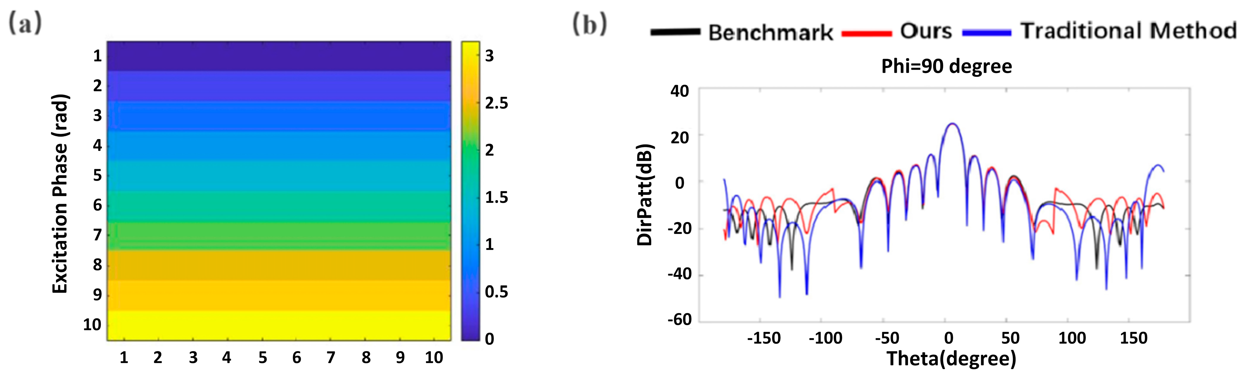
A square antenna array consisting of 100 antenna elements is constructed, with 10 elements on each axis. By adjusting the phase of the excitations, the radiation pattern of this array could be steered. As shown in Figure 4a, the element orders are shown along the x-axis and y-axis, and the stimulated phase is the values in radius format. The excitation phase of each antenna was increased by 20 degrees (0.35 radius) along the y-axis. The calculated radiation pattern results of the phased array using three methods are shown in Figure 4b. The proposed method can fit the full-wave simulation, especially for the side lobes. A detailed comparison with the three methods will be presented in the following section.
4. Discussion
The computational time and memory usage for three examples using full-wave simulations and the unit classification method are summarized and provided in Table 1 for comparison. The mean square error (MSE) values of the calculated directivity for each case using the traditional multiplication method and the proposed method are also presented in Table 2.
The results presented in the tables demonstrate the efficiency and accuracy of the proposed unit classification technique. The proposed method significantly reduces the computational time and memory usage compared to full-wave simulation. The proposed method is particularly advantageous for large-scale cases that require extensive computational resources. The memory usage can be reduced by 94%, and the computational time can be reduced by 96% for the 30 × 30 square array. The MSE values of the proposed method are significantly lower than those of the traditional method, indicating that improved accuracy can be achieved.
Even though the numeral studies were only performed on planar array antennas with linear polarization, the proposed method still works for non-planar arrays and other polarizations since it is a general analytical solution. For arrays with circular polarization, radiation patterns can be obtained with two orthogonal linear polarizations calculated separately. But, for a non-planar array, mutual coupling between adjacent antennas can be varied so much that a complicated and finer classification is needed for a more accurate calculation result.
5. Conclusions
A unit classification technique based on the pattern multiplication method is proposed for a fast and accurate calculation of the radiation pattern for array antennas. In the proposed method, antenna elements are classified into groups according to their position in arrays. Specific antenna elements with different mutual coupling effects and edge effects are full-wave simulated using different boundaries. The multiplication method is then adopted to calculate the radiation pattern of array antennas using simulated results for each antenna element. Three examples are studied, including a square array, a hexagonal array, and a phased array. The numeral results of the computational time and memory usage are provided, as well as the MSE values of the calculated directivity. The numeral study proves that the proposed method significantly improves accuracy while reducing computational time and memory usage, especially for large-scale arrays. The proposed method presents a promising approach for the design and optimization of array antennas in diverse applications. In future research, it would be valuable to investigate the detailed classification method for different array configurations.
Author Contributions
Conceptualization and methodology, H.Z.; simulation, J.L.; writing—original draft preparation, J.L.; writing—review and editing, K.W. All authors have read and agreed to the published version of the manuscript.
Funding
This research received no external funding.
Data Availability Statement
The data presented in this study are available on request from the corresponding author.
Conflicts of Interest
The authors declare no conflict of interest.
References
- Fenn, A.J. Adaptive Antennas and Phased Arrays for Radar and Communications; Artech House: Norwood, MA, USA, 2007. [Google Scholar]
- Zhang, J.; Zhang, S.; Lin, X.; Fan, Y.; Pedersen, G.F. 3D Radiation Pattern Reconfigurable Phased Array for Transmission Angle Sensing in 5G Mobile Communication. Sensors 2018, 18, 4204. [Google Scholar] [CrossRef] [PubMed]
- Zheng, X.; Lin, J.; Wang, Z.; Zhou, H.; He, Q.; Zhou, L. Manipulating light transmission and absorption via an achromatic reflectionless metasurface. PhotoniX 2023, 4, 3. [Google Scholar] [CrossRef]
- Hu, Y.; Liu, X.; Jin, M.; Tang, Y.; Zhang, X.; Li, K.F.; Zhao, Y.; Li, G.; Zhou, J. Dielectric metasurface zone plate for the generation of focusing vortex beams. PhotoniX 2021, 2, 10. [Google Scholar] [CrossRef]
- Shi, T.; Deng, Z.L.; Tu, Q.A.; Cao, Y.; Li, X. Displacement-mediated bound states in the continuum in all-dielectric superlattice metasurfaces. PhotoniX 2021, 2, 7. [Google Scholar] [CrossRef]
- Ma, P.; Wang, P.; Wang, M.; Luo, G.; Yu, L.; Cui, L.; Zhou, X.; Zhang, Y.; Pan, J. A SiN antenna based on grating–waveguide–grating structure for unidirectional and uniform emission. Opt. Commun. 2023, 527, 128959. [Google Scholar] [CrossRef]
- Chandra, R.; Bufler, T.; Narayanan, R. Analysis of planar arrays using Sudoku puzzles for multiple beamforming. In Proceedings of the SPIE Defense + Commercial Sensing, Online, 12–17 April 2021; SPIE: Bellingham, WA, USA, 2021; Volume 11742. [Google Scholar]
- Cheng, D.K. Optimization techniques for antenna arrays. Proc. IEEE 1971, 59, 1664–1674. [Google Scholar] [CrossRef]
- Visser, H.J. Array and Phased Array Antenna Basics; John Wiley & Sons: Hoboken, NJ, USA, 2006. [Google Scholar]
- Kear, F.G. Maintaining the Directivity of Antenna Arrays. Proc. Inst. Radio Eng. 1934, 22, 847–869. [Google Scholar] [CrossRef]
- Lockwood, G.R.; Li, P.C.; O’Donnell, M.; Foster, F.S. Optimizing the radiation pattern of sparse periodic linear arrays. IEEE Trans. Ultrason. Ferroelectr. Freq. Control 1996, 43, 7–14. [Google Scholar] [CrossRef]
- Zhang, J.; Zhang, S.; Ying, Z.; Morris, A.S.; Pedersen, G.F. Radiation-Pattern Reconfigurable Phased Array With p-i-n Diodes Controlled for 5G Mobile Terminals. IEEE Trans. Microw. Theory Tech. 2020, 68, 1103–1117. [Google Scholar] [CrossRef]
- Altair FEKO; Altair Engineering, Inc.: Troy, MI, USA; Available online: https://www.altair.com/feko (accessed on 1 July 2023).
- Vallozzi, L.; Hertleer, C.; Rogier, H. 26—Latest developments in the field of textile antennas. In Woodhead Publishing Series in Textiles, Smart Textiles and Their Applications; Koncar, V., Ed.; Woodhead Publishing: Sawston, UK, 2016; pp. 599–626. ISBN 9780081005743. [Google Scholar] [CrossRef]
- Maffett, A. Array factors with nonuniform spacing parameter. IRE Trans. Antennas Propag. 1962, 10, 131–136. [Google Scholar] [CrossRef]
- Geng, J.; Ren, C.; Wang, K.; Liu, E.; Zhang, J. Generalized Principle of Pattern Multiplication and Its Applications; Springer: Berlin/Heidelberg, Germany, 2022. [Google Scholar]
- Gusevsky, V.I.; Klementyeva, A.V.; Komarov, A.A. A novel method for calculating radiation patters of phased array antennas with an icreased interelement spacing. In Proceedings of the 2017 13th International Conference on Advanced Technologies, Systems and Services in Telecommunications (TELSIKS), Niš, Serbia, 18–20 October 2017; pp. 370–373. [Google Scholar]
- Craeye, C.; González-Ovejero, D. A review on array mutual coupling analysis. Radio Sci. 2011, 46, 1–25. [Google Scholar] [CrossRef]
- Singh, H.; Sneha, H.L.; Jha, R.M. Mutual Coupling in Phased Arrays: A Review. Int. J. Antennas Propag. 2013, 2013, 348123. [Google Scholar] [CrossRef]
- Otero, M.F.; Rojas, R.G. Analysis and treatment of edge effects on the radiation pattern of a microstrip patch antenna. In Proceedings of the IEEE Antennas and Propagation Society International Symposium, 1995 Digest, Newport Beach, CA, USA, 18 June 1995; Volume 2, pp. 1050–1053. [Google Scholar] [CrossRef]
- Pozar, D.M. The active element pattern. IEEE Trans. Antennas Propag. 1994, 42, 1176–1178. [Google Scholar] [CrossRef]
- Kelley, D.F.; Stutzman, W.L. Array antenna pattern modeling methods that include mutual coupling effects. IEEE Trans. Antennas Propag. 1993, 41, 1625–1632. [Google Scholar] [CrossRef]
- Yang, X.S.; Qian, H.; Wang, B.Z.; Xiao, S. Radiation Pattern Computation of Pyramidal Conformal Antenna Array with Active-Element Pattern Technique. IEEE Antennas Propag. Mag. 2011, 53, 28–37. [Google Scholar] [CrossRef]
- Yang, K.; Zhao, Z.; Nie, Z.; Ouyang, J.; Liu, Q.H. Synthesis of Conformal Phased Arrays With Embedded Element Pattern Decomposition. IEEE Trans. Antennas Propag. 2011, 59, 2882–2888. [Google Scholar] [CrossRef]
- Gan, L.; Jiang, W.; Chen, Q.; Li, X.; Zhou, Z.; Gong, S. Method to Estimate Antenna Mode Radar Cross Section of Large-Scale Array Antennas. IEEE Trans. Antennas Propag. 2021, 69, 7029–7034. [Google Scholar] [CrossRef]
- Zwamborn, P. A new approach of pattern synthesis for array antennas of arbitrary geometry using the Conjugate Gradient method. In Proceedings of the 1992 Symposium on Antenna Technology and Applied Electromagnetics, Winnipeg, MB, Canada, 5–7 August 1992; pp. 80–85. [Google Scholar] [CrossRef]
- Zhang, S.; Wang, C.; Huang, D.; Han, H.; Bai, M. A Generalizing Radiation Pattern Synthesis Method for Conformal Antenna Array Based on Convolutional Neural Network. In Proceedings of the 2022 IEEE 9th International Symposium on Microwave, Antenna, Propagation and EMC Technologies for Wireless Communications (MAPE), Chengdu, China, 26–29 December 2022; pp. 212–216. [Google Scholar] [CrossRef]
- Kim, J.H.; Choi, S.W. A Deep Learning-Based Approach for Radiation Pattern Synthesis of an Array Antenna. IEEE Access 2020, 8, 226059–226063. [Google Scholar] [CrossRef]
- Balanis, C.A. Antenna theory: Analysis and design. IEEE Antennas Propag. Soc. Newsl. 2003, 24, 28–29. [Google Scholar] [CrossRef]
- Liu, X.; Zhao, H.; Hu, J. The Edge Diffraction Effect on the Radiation Pattern of Elements for Antenna Array Synthesis. In Proceedings of the 2021 IEEE International Symposium on Antennas and Propagation and USNC-URSI Radio Science Meeting (APS/URSI), Singapore, 4–10 December 2021; pp. 1461–1462. [Google Scholar] [CrossRef]
Figure 1.
Unit classification method: (a) schematic of a square array with patch antennas; (b) classification diagram; (c) three views of the patch antenna element; (d) nine units simulation boundaries; (e) unit used in traditional multiplication methods.
Figure 1.
Unit classification method: (a) schematic of a square array with patch antennas; (b) classification diagram; (c) three views of the patch antenna element; (d) nine units simulation boundaries; (e) unit used in traditional multiplication methods.

Figure 2.
Square array calculation results comparison: (a) radiation pattern results at phi = 0 degree plane; (b) radiation pattern results of front side and backside at phi = 0 degree plane.
Figure 2.
Square array calculation results comparison: (a) radiation pattern results at phi = 0 degree plane; (b) radiation pattern results of front side and backside at phi = 0 degree plane.

Figure 3.
Hexagonal array results comparison: (a) schematic and classification diagram of a hexagonal array; (b) radiation pattern results comparison at phi = 90 degree plane.
Figure 3.
Hexagonal array results comparison: (a) schematic and classification diagram of a hexagonal array; (b) radiation pattern results comparison at phi = 90 degree plane.

Figure 4.
Phased array calculation results comparison: (a) the excitation phase distribution; (b) radiation pattern results of the phased array at phi = 90 degree plane.
Figure 4.
Phased array calculation results comparison: (a) the excitation phase distribution; (b) radiation pattern results of the phased array at phi = 90 degree plane.

Table 1.
Computational memory and time of the full-wave simulation and the proposed method.
| Method | Numerical Examples | Memory/GByte | Time/Hours |
|---|---|---|---|
| Full-wave Simulation | 30 × 30 square array | 3.42 | 6.25 |
| 352-element hexagonal array | 0.98 | 1.83 | |
| 10 × 10 phased array | 0.38 | 0.5 | |
| Proposed Method | 30 × 30 square array | 0.22, ↓ 94% | 0.28, ↓ 96% |
| 352-element hexagonal array | 0.22, ↓ 76% | 0.28, ↓ 85% | |
| 10 × 10 phased array | 0.22, ↓ 42% | 0.28, ↓ 44% |
Table 2.
MSE of the traditional method and the proposed method according to benchmark.
| Method | Numerical Examples | MSE |
|---|---|---|
| Traditional Method | 30 × 30 square array | 100.30 |
| 352-element hexagonal array | 109.20 | |
| 10 × 10 phased array | 96.78 | |
| Proposed Method | 30 × 30 square array | 33.85, ↓ 66% |
| 352-element hexagonal array | 22.15, ↓ 80% | |
| 10 × 10 phased array | 32.18, ↓ 67% |
Disclaimer/Publisher’s Note: The statements, opinions and data contained in all publications are solely those of the individual author(s) and contributor(s) and not of MDPI and/or the editor(s). MDPI and/or the editor(s) disclaim responsibility for any injury to people or property resulting from any ideas, methods, instructions or products referred to in the content. |
© 2023 by the authors. Licensee MDPI, Basel, Switzerland. This article is an open access article distributed under the terms and conditions of the Creative Commons Attribution (CC BY) license (https://creativecommons.org/licenses/by/4.0/).
Share and Cite
MDPI and ACS Style
Zhou, H.; Li, J.; Wei, K. A Novel Unit Classification Method for Fast and Accurate Calculation of Radiation Patterns. Electronics 2023, 12, 3512. https://doi.org/10.3390/electronics12163512
AMA Style
Zhou H, Li J, Wei K. A Novel Unit Classification Method for Fast and Accurate Calculation of Radiation Patterns. Electronics. 2023; 12(16):3512. https://doi.org/10.3390/electronics12163512
Chicago/Turabian StyleZhou, Hao, Jiren Li, and Kun Wei. 2023. "A Novel Unit Classification Method for Fast and Accurate Calculation of Radiation Patterns" Electronics 12, no. 16: 3512. https://doi.org/10.3390/electronics12163512
Note that from the first issue of 2016, this journal uses article numbers instead of page numbers. See further details here.