
High Gain and Wide-Angle Continuous Beam Scanning SIW Leaky-Wave Antenna


1
Department of ECE, FET, Gurukula Kangri (Deemed To Be University), Haridwar 249404, Uttarakhand, India
2
Biomedical Engineering Department, Al-Mustaqbal University College, Hillah 51001, Babil, Iraq
*
Authors to whom correspondence should be addressed.
Electronics 2023, 12(2), 370; https://doi.org/10.3390/electronics12020370
Submission received: 9 December 2022
/
Revised: 5 January 2023
/
Accepted: 9 January 2023
/
Published: 11 January 2023
(This article belongs to the Special Issue Innovative Antenna Systems: Challenges, Developments, and Applications)
Abstract
:A novel substrate integrated waveguide (SIW) adopting a leaky-wave antenna (LWA) for continuous beam scanning for tri bands is presented. For continuous beam scanning (CBS), optimization of different parameters associated with the unit cell has been carried out. Apart from this, optimal impedance matching is also obtained with the help of the characteristic impedance of the waveguide. The proposed SIW LWA scans from −58° to + 59° along with 14.50 dBi gain when the frequency changes from 10 GHz to 18.22 GHz and provides a scanning rate of 14.23. The beauty of the suggested antenna is its smaller size and high gain, along with a wider scanning range (117°) capability. This antenna’s final prototype has been fabricated, and the measurement results are matched with the simulation results.
Keywords:
antenna; tri bands; SIW; return loss; LWA; SIW; leaky-wave antenna; continuous beam scanning (CBS)1. Introduction
The first pioneer of the leaky-wave antenna was W.W. Hansen [1]. He first described it in a closed rectangular waveguide. A leaky-wave antenna (LWA), having a certain slotted wave guiding structure, may transmit electromagnetic energy into a free environment with the help of coupling that is provided in between guided modes and radiation modes [2,3]. In fast-growing wireless communication, antennas play a key role because of their various authentic applications. Different types of antennae have been developed, and many more are continuously developed. LWAs have received widespread attention due to a variety of advantages, including their frequency beam-scanning capabilities, low profile, simple feeding mechanism, ease of integration with onboard circuitry, and so on [4,5]. LWAs are classified into a few types based on their antenna construction, such as periodic and uniform (or quasi-uniform) kinds of LWAs [6]. A traditional uniform kind of LWA normally transmits through a fast wave, which means that the guided wave’s phase constant is less than the wave number. In essence form, a uniform LWA enables beam scanning from the negative side (backward) to the positive side (forward). Similarly, a Floquet model of the field also provides transmission from other variants of LWA called quasi-uniform, having a period considerably lower compared with the wavelength. These types of quasi-uniform LWAs have both negative and positive effective propagation indices, and may perform well by incorporating CRLH (composite right left hand) in both directions, i.e., backward and forward [7,8,9]. Higher-order frequency modes aid in the coupling of waves of a slow nature to the modes of radiation, while periodic LWA (PLWA) provide frequency beam-scanning in backward as well forward directions [10,11,12,13]. However, because of the OSB (open stop band), traditional Periodic LWAs (PLWAs) can scarcely guarantee continuous beam scanning (CBS) for a broadside. As a result, the radiation performance is compromised and cannot meet practical requirements, such as a wider range of scanning from the backward direction (negative side) to the forward direction (positive side) along with quick transient responses, which is essential for radar, VSAT (very small aperture terminal), electromagnetic imaging systems and broadcast satellite [14,15,16]. A unique LWA is derived on multilayered CRLH for CBS from the negative side (or backward direction) to the positive side (or forward direction) along with constant gain [17]. An antenna is made up of an array of unit cells of CRLH on a SIW that has a wide range of scanning, although it provides poor gain. A stepped impedance resonator (SIR)-based CRLH-LWA in which balanced condition is created by using the SIR approach on a typical CRLH structure and adjusting the SIR settings is presented in [18]. In order to achieve the balanced condition, the structure does not need an interdigital or multilayered capacitor. To accomplish broadside radiation, a series feeding design “herringbone” microstrip travelling wave array of antenna is used that gives circularly polarized orientation. It is illustrated that these structures are accepted as a leaky wave with periodic geometry, giving information about important radiation properties such as the structure’s directivity and beam angle, especially at broadside [19]. Another is the Ridged Substrate Integrated Waveguide (RSIW)-based LWA array providing minimal cross polarization with periodic slots [20]. To build a periodic kind of leaky-wave antenna (PLWA), which is capable of backward to forward scanning, parametric restrictions of the structure were examined. For the suggested antenna, a Transverse Equivalent Network (TEN) for multimode is proposed, and values of phase constants and leakage rates for various construction quality parameters were recovered by a technique called transverse resonance [20]. In [21], it is discussed and experimentally proven that a 1-D planar periodic comb line LWA can be designed to prevent open-stop band effects when the scanning of the beam is performed via broadside. This antenna exhibits single beam scanning and radiates from approximately resonant stubs, which guarantees a minimal leakage along with high directivity.
A novel single-conductor transmission line called a Goubau line gives low-loss transmission capabilities and is simple to integrate [22]. It is a periodic LWA derived from a dielectric substrate and a planar Goubau transmission line. The Goubau line is periodically modulated to produce the leaky-wave radiations. By gaining more momentum in a similar fashion, the Goubau line effectively enables the slow-wave mode that reaches the fast-wave area for radiations. Further, the Goubau line LWAs can constantly guide the main beam from the negative side to the positive side for the working band of frequencies with the aid of periodic modulations. However, the broadside radiation efficiency of the LWAs is often low and we investigated both kinds of transversally and longitudinally asymmetrical schemes of modulations for Goubau lines in order to get around this limitation. These cutting-edge Goubau line LWAs have excellent promise for very demanding millimeter-wave and terahertz systems [22]. Through frequency scanning, their ability to direct beams from backfire to endfire is demonstrated using the unique technique CRLH. It is suggested that for CBS applications researchers should use CRLH-incorporated SIW and other variants such as half mode SIW (HMSIW) derived designs for leaky wave which also suppress the OSB (open stop band) issue [23], due to which they represent potential millimeter wave and microwave antenna candidates.
Another structure suggests a CBS from the negative side to the positive side HMSIW-derived LWA consisting of folded ground [24]. Additionally, even at the broadside, this kind of antenna provides strong radiation gain. In comparison with earlier reported HMSIW leaky-wave antennas, the suggested antenna’s transverse size could be further reduced since a folded ground structure is applied to prevent leakage of energy through the open periphery of HMSIW. At Ku band, a unique compact size with a good gain CRLH-derived LWA in which a HMSIW is used along with an appropriately oriented complementary quad spiral resonator (CQSR) [25]. A CQSR realizes the unit cell in such a fashion that the orientation of spirals shows a high amount of leakage loss with minimal cross-coupling. In visible space, LWAs can scan backward and forward as well as in a broadside orientation. The key task of CBS is achieved by appropriately optimizing all the parameters of the unit cell of LWA through optimal impedance matching with the characteristic impedance of the waveguide structure [26]. Recently, a periodic design of LWA has been proposed that scans from the negative to the positive side, and the H plane step discontinuity is used for stop band suppression [27]. Another two-part unit cell-based leaky-wave antenna has been developed for continuous wave scanning without the degradation of gain on both sides, and the removal of OSB has been proposed, providing a 95-degree scanning from −61° to +34° [28]. The proposed SIW LWA should be a viable alternative for tri bands (X, Ku and K) applications such as static satellite services, VSAT, satellite broadcast services and radar services. For CBS applications, the proposed SIW LWA provides a wider angle (or range) of scanning.
This work proposed a novel compact SIW-LWA made up of rectangular units that has wide-angle beam-scanning capabilities and very high gain. Finally, in order to design the SIW-LWA, the SIW platform will be needed along with periodic slots. This article provides a ground-breaking LWA design based on SIW technology that offers higher gain and wider CBS for tri bands (X, Ku and K bands) applications.
2. Design and Analysis of SIW LWA
2.1. Design Theory
The proposed SIW-LWA is created by adding rectangular slots in the sectional view of the waveguide. The proposed design has two parallel rows of rectangular slots along with four additional smaller rectangular small slots on each corner which provide periodic modulation. There are an endless number of space harmonics produced by these perturbations. For the formation of single beam in PLWAs, just one fast harmonic should be radiated. The fast wave generally produced complex leaky propagation constant having space harmonic (n = 1 or the n = 0) is steered along the line. The unit cell’s period P affects the phase constant [26].
where P stands for the period and for the unperturbed transmission line’s basic phase constant.
The phase constant parameter value for the unperturbed SIW of TE10 fundamental mode is obtained by using the equation mentioned in [29]. As the phase transitions from negative to positive after passing the zero line, the variation in phase constant occurred. As a result of which, negative side (backward) to positive side (forward) frequency beam scanning occurs. Although, radiations from such LWAs at broadside are constrained by an OSB which occur at the broadside frequency brought on by standing wave generation, this results in an unsatisfactory radiation pattern which shows poor scanning capability and a considerable return loss [4,5]. The attenuation and phase constant are the key parameters for the designing of LWA. Once these details are found, it is possible to compute the range of the main beam for LWA as
where indicates primary beam range (or angle) measured and represents wave number for free space. Now, the optimum length (L) of the LWA is chosen so that more than 90% of its power should radiate when reaching the target load and it is expressed as
In our work, periodic modulations produce the harmonic n = −1. If on the broadside, Equation (1) applies as follows.
where guided wavelength is indicated by . We may infer from Equation (4) that the unit cell’s period is equal to the guided wavelength for CBS.
2.2. Geometry
The construction of the unit cell, as well as the array of proposed SIW-LWA, is depicted in Figure 1. The proposed SIW-LWA has an antenna length of 147 mm or 6.84 λ0 at 13.76 GHz which is made up of 10-unit cells. The unit cell is made up of SIW technology, having two parallel electric walls which are formed through vias. The distance ‘S’ (≤2D) between the vias and their diameter ‘D’ (<λg/5) are each 2 mm and 1 mm, respectively. We select the SIW’s width depending on our target frequency range using the formulas in [30]. The antenna is fed from the left side and impedance matched using a 50 Ω termination. Table 1 lists the values for the various unit cell parameters. To enable the SIW to work as an LWA, rectangular slots are carved onto the top patch surface. In addition to the four small corner slots, a parallel rectangular-horizontal slot is created to permit the leaky-wave radiation. The band gap in the dispersion figure is the consequence of first cutting horizontal slits into the top wall of the SIW [31]. For the elimination of the OSB issue in the unit cell in an efficient way different components can be used in shunt and series fashions [30]. The small slots in the corners can be thought of as a combination of four opposing slots which eliminate the OSB problem from the proposed SIW LWA.
The two parallel rectangular slots in unit cell having length equal to λg/4. The normalized phase constant is shown in Figure 2 using Equation (5).
where S11 and S21 are the parameters of scattering.
The dispersion plot demonstrates that as the frequency rises, the value of the phase constant shifts from the negative side to the positive side and provides CBS at 13.76 GHz as shown in Figure 2. The optimal impedance matching is obtained by adding smaller slots to additional corners, which are positioned in opposition, and this is necessary for the slots to radiate as much as possible.
The parametric analysis for the scattering parameter (S11) for the length of parallel longitudinal slots of the SIW LWA is shown in Figure 3. The matching of the antenna is significantly influenced by the length of longitudinal slots. The longitudinal slots must be 5.56 mm long to achieve the optimal impedance matching, which is also necessary to get the maximum leakage of radiation from the slots. The electric field distributions of the simulated results for SIW at 13.76 GHz frequency show the perfect platform for the designing of LWA, as depicted in Figure 4. The electric fields around the input port are more intense than those surrounding the output port, which proved the authenticity of the SIW to make the suggested SIW leaky-wave antenna provide a higher gain and a wider range of scanning from the negative side (backward) to the positive side (forward). Both these orientations, backwards as well as forwards, are caused by the phase and group velocity’s anti-parallel and parallel directions. It is found that by increasing the length of antenna, the field strength decreases. The field intensity also fluctuates with the frequency of operation, as seen in Figure 4. For broadside radiation, no electromagnetic radiation is transmitted into the SIW LWA because standing wave patterns appear at broadside radiation frequency in SIW LWAs. In contrast, the infinite guided wavelength is seen in our LWA at transition frequencies (13.76 GHz) for SIW-LWA, and no field fluctuations are found. However, when the value of group velocity becomes nonzero, then the wave keeps moving, and radiating energy is given into the LWA, supporting the CBS for LWA.
3. Experimental Results
3.1. Geometry
The SIW is used in designing and fabricating the LWA, which provides CBS. The antenna’s built prototype is shown in Figure 5. A tapered microstrip transmission line ends with a load equivalent to the characteristic impedance that feeds the LWA. The HFSS software is used to achieve the best matching, and the dimensions of the tapered line are optimized using ANYSS HFSS software. Initially, two parallel longitudinal slots are made, which caused the OSB problem. However, after experimental work without using any complex OSB removal technique, four additional small slots were placed at the corners of parallel longitudinal slots, which addressed the OSB problem. After the optimization process, the obtained length and width for the tapered line are 6.25 mm and 7.6 mm, respectively. The Rogers substrate is used for the SIW LWA with a loss tangent of 0.009, a thickness of 0.787 mm, and a dielectric permittivity of 2.2.
3.2. S Parameters
The simulation and measurement reflection coefficients (S11) and transmission coefficients (S21) for the SIW LWA are shown in Figure 6 for the presented SIW LWA. As per the simulations of the reflection coefficient (S11) for the SIW LWA, the broadside impedance matching at 13.76 GHz is almost perfect. At that specific frequency, the difference in the S21 scattering parameter causes a significant gain, and then the gain begins to decline. The measurement results are somewhat more because of fabrication flaws and deliberate mistakes made during testing of LWA, but they are almost identical to the simulated findings. According to the measurements, LWA’s reflection coefficients (S11) are less than −10 dB for 10 GHz to 18.22 GHz bands.
3.3. Radiation Properties
The normalised y–z plane radiation patterns of the proposed design of the SIW leaky-wave antenna for simulation and measurement are shown in Figure 7. The setup for testing the antenna in the anechoic room is depicted in Figure 8. While the frequency changes from 10 GHz to 18.22 GHz, the beam scans from −58° to +59° for the proposed SIW LWA. The observation yield of a total beam scanning range of 117 degrees is achieved. The beam goes from −58° at 10 GHz from the backward to the forward direction and points at +59° at 18.22 GHz as the frequency increases. Therefore, the total achieved beam scanning range for tri bands (X, Ku and K) is 117°, which is more than existing SIW leaky-wave antennas as shown in Table 2. The scanning rate is the ratio of the scanning range and the relative bandwidth, and the obtained scanning rate for the proposed antenna is 14.23. Currently, OSB suppression and a high scanning rate while maintaining the optimum gain are significant challenges for the SIW LWA. These challenges are overcome by the proposed antenna, and it also provides scanning on both sides, negative as well as positive.
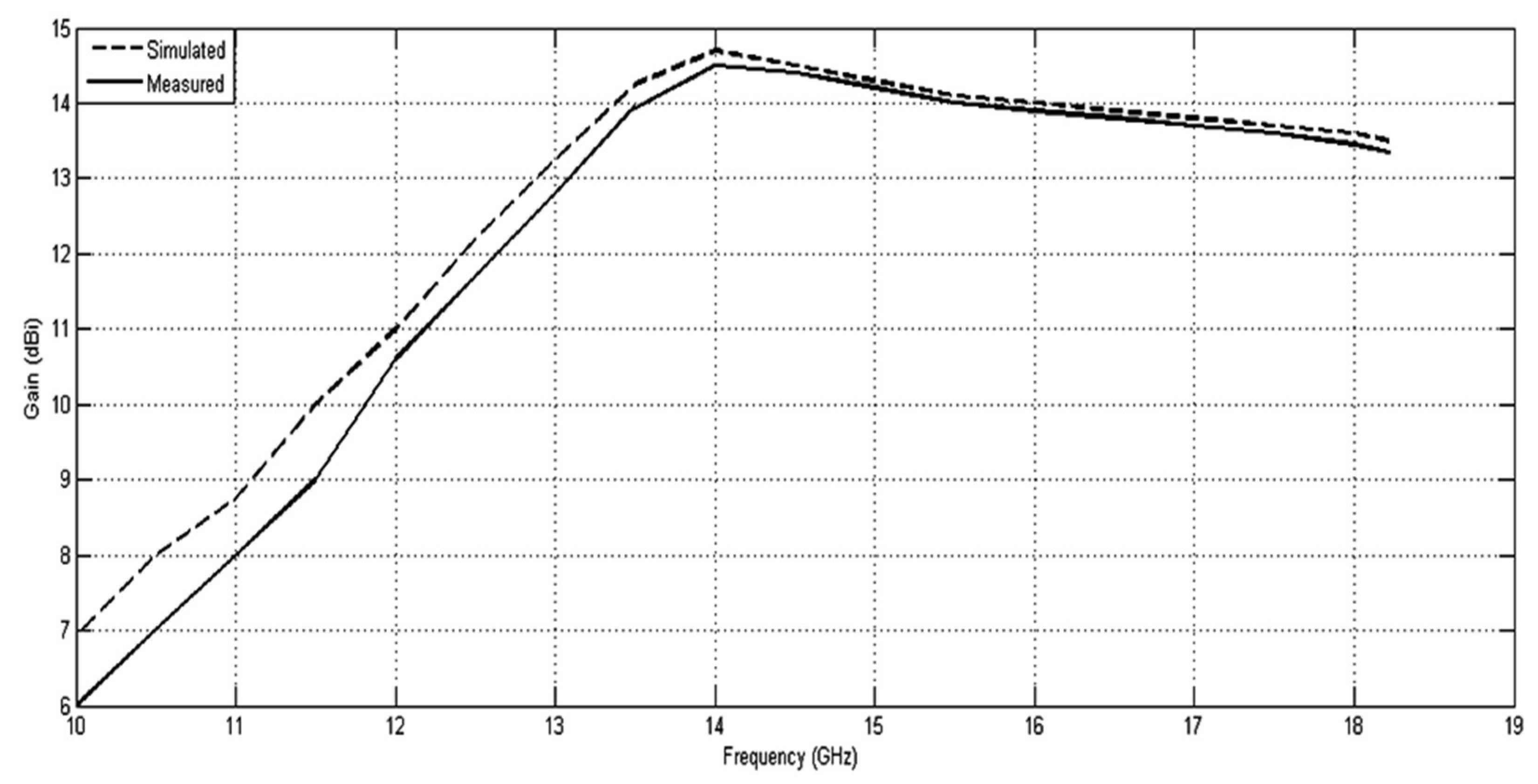
The primary lobe directions for the SIW LWA are depicted in Figure 9. The scanning angle range of the proposed SIW LWA is greater than the existing SIW LWAs because the radiation in each longitudinal slot in the SIW LWA dissipates at the endfire. The obtained gain pattern for the described SIW LWA is displayed in Figure 10. The gain values from the measurements and simulations are almost identical. Although, after analysis, it is found that the substrate’s losses and connectors are the primary causes of the discrepancy between the simulation and the measurement gain of the proposed SIW LWA, resulting in a shift of nearly 1 dB. The highest gain attained for the SIW LWA is 14.5 dBi, which is suitable for 5G antenna applications. Table 2 displays comparable similar reported designs along with quality parameters. The length (P) of the unit cell for the proposed SIW LWA is almost equal to the guided wavelength (λg). Nevertheless, this design is derived on a composite right left-handed (CRLH) scheme having a unit length P < λg/4, meaning their manufacturing becomes complex. Therefore, the presented antenna is much easier to fabricate than others that demonstrate the originality of the suggested SIW LWA. Additionally, Table 2 shows that the proposed antenna is significantly smaller than the SIW-based leaky-wave antennas.
4. Conclusions
A novel and efficient SIW LWA design implementing SIW technology is introduced. The length of the proposed SIW LWA is 7.5 λ0, and it provides continuous beam scanning that covers X, Ku and K bands along with a maximum gain of 14.5 dBi. The frequency responses for the SIW LWA and the radiation patterns are simulated and measured. The beam angle scans from −58° to +59° for the suggested novel SIW LWA along with 14.5 dBi gain. The simulation and measurement results strongly proved that the recommended SIW LWA has CBS capability through backward to forward directions. The key benefits of this SIW LWA are cheap cost, low profile, simple integration, CBS capability, and that it works for X, Ku and K Bands.
Author Contributions
Conceptualization, V.A. and T.G.; methodology, V.A., T.G. and H.M.R.A.-K.; software, V.A., T.G. and H.M.R.A.-K.; validation, V.A., T.G. and H.M.R.A.-K.; formal analysis, V.A., T.G. and H.M.R.A.-K.; investigation, V.A. and H.M.R.A.-K.; resources, V.A., T.G. and H.M.R.A.-K.; writing—original draft preparation, V.A., T.G. and H.M.R.A.-K.; writing—review and editing, V.A., T.G. and H.M.R.A.-K.; visualization, T.G. and H.M.R.A.-K.; supervision, T.G.; project administration, T.G. All authors have read and agreed to the published version of the manuscript.
Funding
This research received no external funding.
Informed Consent Statement
Not applicable.
Data Availability Statement
All data are available in this paper.
Conflicts of Interest
All the authors declare that there is no conflict of interest.
References
- Hansen, W.W. Radiating Electromagnetic Waveguide. U.S. Patent 2,402,622,1940, 26 November 1940. [Google Scholar]
- Chen, S.L.; Karmokar, D.K.; Li, Z.; Qin, P.Y.; Ziolkowski, R.W.; Guo, Y.J. Circular polarized substrate integrated waveguide leaky-wave antenna with wide-angle and consistent-gain continuous beam scanning. IEEE Trans. Antennas Propag. 2019, 67, 4418–4428. [Google Scholar] [CrossRef]
- Fuscaldo, W.; Jackson, D.R.; Galli, A. General formulas for the beam properties of 1-D bidirectional leaky-wave antennas. IEEE Trans. Antennas Propag. 2019, 67, 3597–3608. [Google Scholar] [CrossRef]
- Arya, V.; Garg, T. Leaky Wave Antenna: Past and Present. In Proceedings of the Integrated Intelligence Enable Networks and Computing, Algorithms for Intelligent Systems, Chamoli, India, 5–7 September 2020. [Google Scholar] [CrossRef]
- Arya, V.; Garg, T. Leaky wave antenna: A historical development. Microw. Rev. 2021, 27, 3–16. [Google Scholar]
- Lyu, Y.; Member, S.; Liu, X. Leaky-wave antennas based on non-cutoff substrate integrated waveguide supporting beam scanning from backward to forward. IEEE Trans. Antennas Propag. 2016, 64, 2155–2164. [Google Scholar] [CrossRef]
- Sabahi, M.M.; Heidari, A.A.; Movahhedi, M. A compact CRLH circularly polarized leaky-wave antenna based on substrate integrated waveguide. IEEE Trans. Antennas Propag. 2018, 66, 4407–4414. [Google Scholar] [CrossRef]
- Paulotto, S.; Baccarelli, P.; Frezza, F.; Jackson, D.R. A novel technique for open-stopband suppression in 1-D periodic printed leaky-wave antennas. IEEE Trans. Antennas Propag. 2009, 57, 1894–1906. [Google Scholar] [CrossRef]
- Jackson, D.R.; Oliner, A.A. Leaky-Wave Antennas: Modern Antenna Handbook; Wiley: Hoboken, NJ, USA, 2008. [Google Scholar]
- Ranjan, R.; Ghosh, J. SIW based leaky wave antenna supporting wide range of beam scanning through broadside. IEEE Antenna Wirel. Propag. Lett. 2019, 18, 606–610. [Google Scholar] [CrossRef]
- Saghati, A.P.; Mirsalehi, M.M.; Neshati, M.H. A HMSIW circularly polarized leaky-wave antenna with backward, broadside, and forward radiation. IEEE Antennas Wirel. Propag. Lett. 2014, 13, 451–454. [Google Scholar] [CrossRef]
- Tiwari, A.K.; Awasthi, S.; Singh, R.K. A symmetrical periodic leaky wave antenna with backward to forward scanning. IEEE Antennas Wirel. Propag. Lett. 2020, 19, 646–650. [Google Scholar] [CrossRef]
- Paulotto, S.; Baccarelli, P.; Jackson, D. A self-matched wide scanning U-stub microstrip periodic leaky-wave antenna. J. Electr. Waves Appl. 2014, 28, 151–164. [Google Scholar] [CrossRef]
- Zheng, D.; Lyu, Y.-L.; Wu, K. Transversely slotted SIW leaky-wave antenna featuring rapid beam-scanning for millimeter-wave applications. IEEE Trans. Antennas Propag. 2020, 68, 4172–4185. [Google Scholar] [CrossRef]
- Karmokar, D.K.; Esselle, K.P. Periodic U-slot-loaded dual-band half-width microstrip leaky-wave antennas for forward and backward beam scanning. IEEE Trans. Antennas Propag. 2015, 63, 5372–5381. [Google Scholar] [CrossRef]
- Karmokar, D.K.; Guo, Y.J.; Qin, P.-Y.; Esselle, K.P.; Bird, T.S. Forward and backward beam-scanning Tri-band leaky-wave antenna. IEEE Antennas Wirel. Propag. Lett. 2017, 16, 1891–1894. [Google Scholar] [CrossRef]
- Nasimuddin; Chen, Z.N.; Qing, X. Multilayered composite right/left-handed leaky-wave antenna with consistent gain. IEEE Trans. Antennas Propag. 2012, 57, 5056–5062. [Google Scholar] [CrossRef]
- Kushiyama, Y.; Arima, T.; Uno, T. Differential type C.R.L.H. leaky-wave antenna using stepped impedance resonators. IEEE Antennas Wirel. Propag. Lett. 2016, 15, 321–324. [Google Scholar] [CrossRef]
- Cameron, T.R.; Sutinjo, A.T.; Okoniewski, M. A circularly polarized broadside radiating “Herringbone” array design with the leaky-wave approach. IEEE Antennas Wirel. Propag. Lett. 2010, 9, 826–829. [Google Scholar] [CrossRef]
- Mallahzadeh, A.; Mohammad-Ali-Nezhad, S. Periodic collinear slotted leaky wave antenna with open stopband elimination. IEEE Trans. Antennas Propag. 2015, 63, 5512–5521. [Google Scholar] [CrossRef] [Green Version]
- Williams, J.T.; Baccarelli, P.; Paulotto, S.; Jackson, D.R. 1-D combline leaky wave antenna with the open stopband suppressed: Design considerations and comparisons with measurements. IEEE Trans. Antennas Propag. 2013, 61, 4484–4492. [Google Scholar] [CrossRef]
- Tang, X.-L.; Zhang, Q.; Hu, S.; Zhuang, Y.; Kandwal, A.; Zhang, G.; Chen, Y. Continuous beam steering through broadside using asymmetrically modulated Goubau line leaky-wave antennas. Sci. Rep. 2011, 7, 11685. [Google Scholar] [CrossRef] [Green Version]
- Dong, Y.; Itoh, T. Composite right/left-handed substrate integrated waveguide and half mode substrate integrated waveguide leaky wave structures. IEEE Trans. Antennas Propag. 2011, 59, 767–775. [Google Scholar] [CrossRef]
- Liu, L.; Gu, X.; Zhu, L.; Rong, Y.; Qian, H. A novel half mode substrate integrated waveguide leaky-wave antenna with continu- ous forward-to-backward beam scanning functionality. Int. J. RF Microw. Comput. Eng. 2018, 28, e21559. [Google Scholar]
- Sarkar, A.; Adhikary, M.; Sharma, A.; Biswas, A.; Akhtar, M.J.; Hu, Z. Composite right/left-handed based compact and high gain leaky-wave antenna using complementary spiral resonator on HMSIW for Ku band applications. IET Microw. Antennas Propag. 2018, 12, 1310–1315. [Google Scholar] [CrossRef] [Green Version]
- Prakash, V.; Kumawat, S.; Singh, P. Design and analysis of full and half mode substrate integrated waveguide planar leaky wave antenna with continuous beam scanning in X-Ku band. Frequenz 2019, 73, 171–178. [Google Scholar] [CrossRef]
- Kamalzadeh, S.; Soleimani, M. A Novel SIW Leaky-Wave Antenna for Continuous Beam Scanning from Backward to Forward. Electronics 2022, 11, 1804. [Google Scholar] [CrossRef]
- Sohrabi, P.; Rezaei, P.; Kiani, S. A symmetrical SIW-based leaky—wave antenna with continuous beam scanning from from backward-to-forward through broadside. Wirel. Netw. 2021, 27, 5417–5424. [Google Scholar] [CrossRef]
- Zhou, W.; Liu, J.; Long, Y. Investigation of shorting vias for suppressing the open stopband in an SIW periodic leaky wave structure. IEEE Trans. Microw. Theory Tech. 2018, 66, 1–10. [Google Scholar] [CrossRef]
- Xu, F.; Wu, K. Guided wave and leakage characteristics of substrate integrated waveguide. IEEE Trans. Microw. Theory Tech. 2005, 53, 66–72. [Google Scholar]
- Liu, J.; Tang, X.; Li, Y.; Long, Y. Substrate integrated waveguide leaky-wave antenna with H-shaped slots. IEEE Trans. Antennas Propag. 2005, 60, 3962–3967. [Google Scholar] [CrossRef]
Figure 1.
(a) Unit cell for SIW LWA; (b) Structure of SIW LWA.
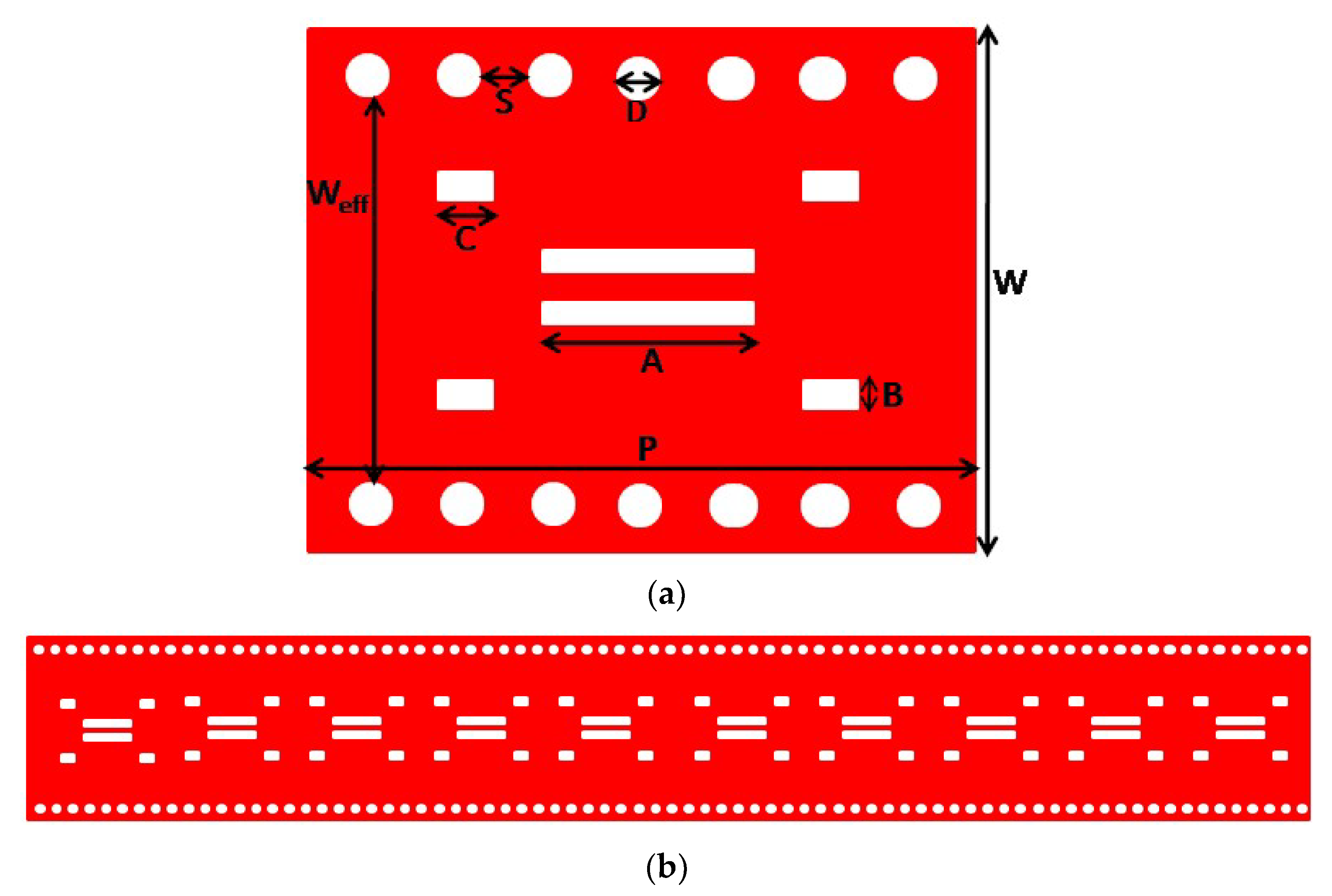
Figure 2.
Dispersion diagram for unit cell.
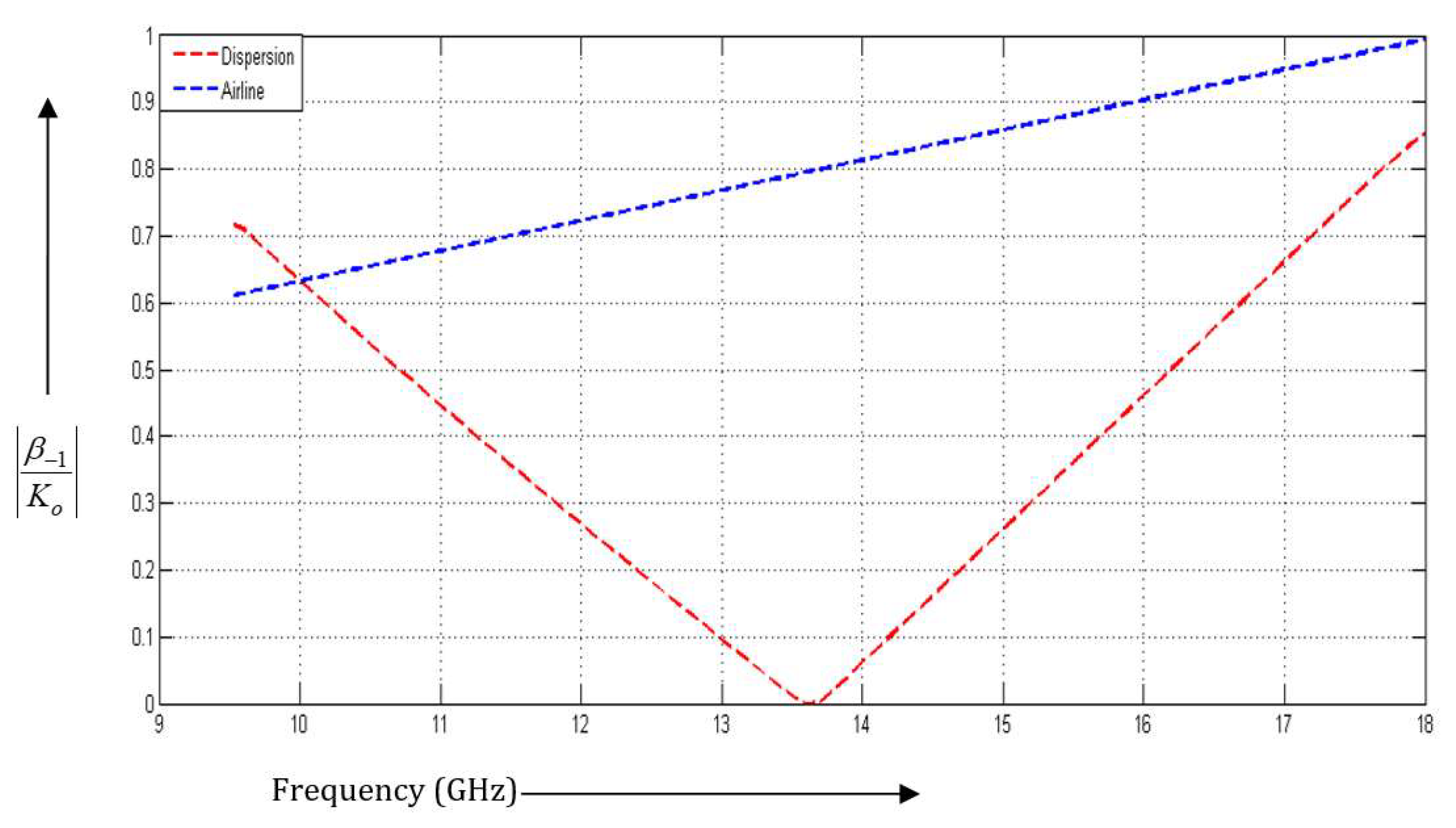
Figure 3.
Parametric analysis for the length of parallel longitudinal slots of SIW LWA.
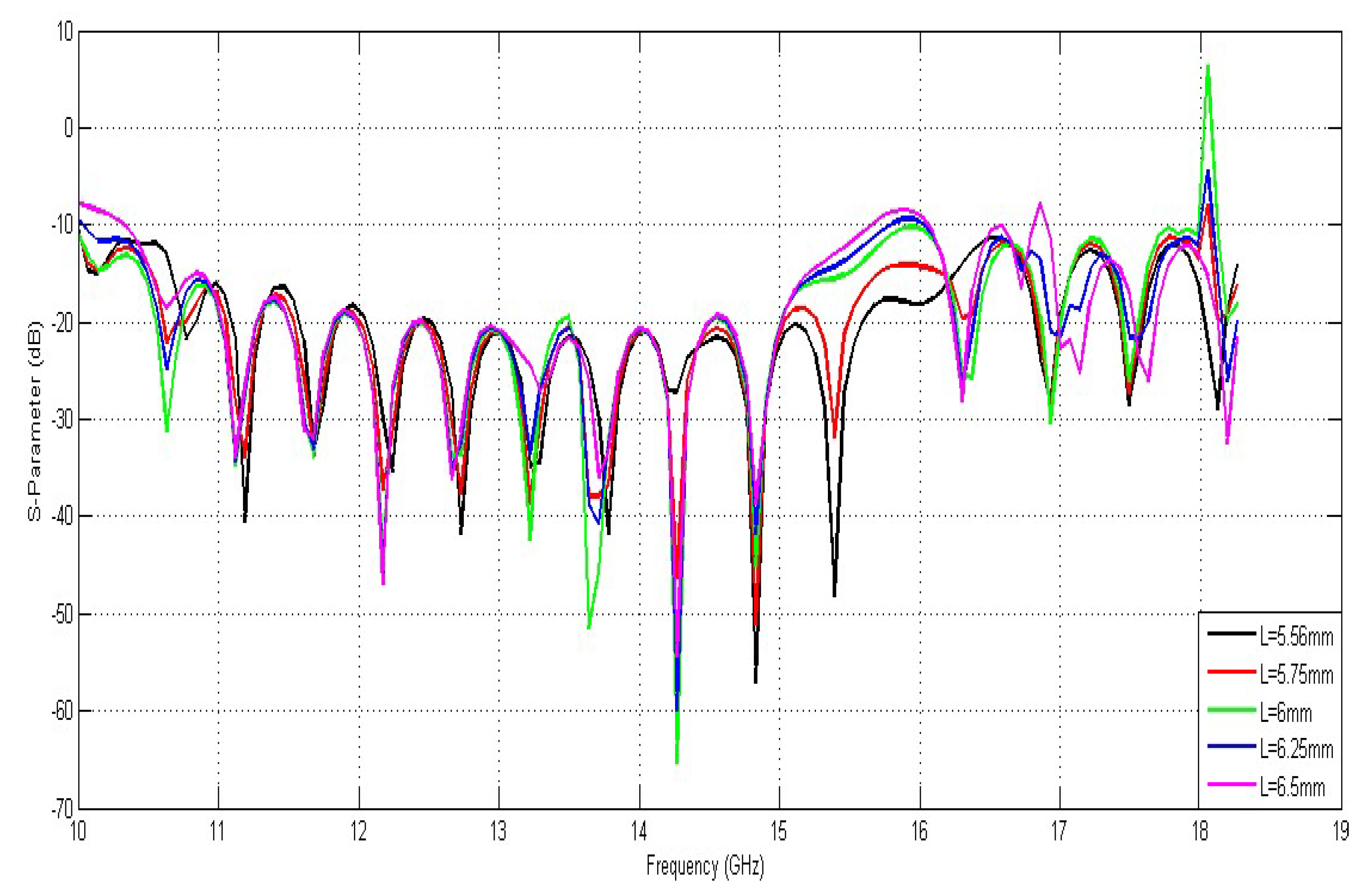
Figure 4.
Electric field distribution for the SIW.
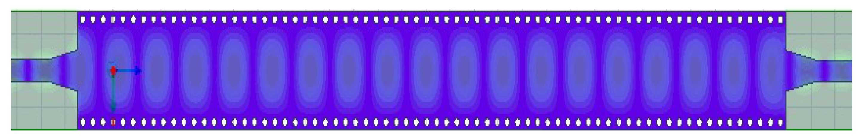
Figure 5.
Fabricated prototype of SIW LWA.

Figure 6.
Simulated and measured S11 and S21 parameters for SIW LWA achieved from the measurements.
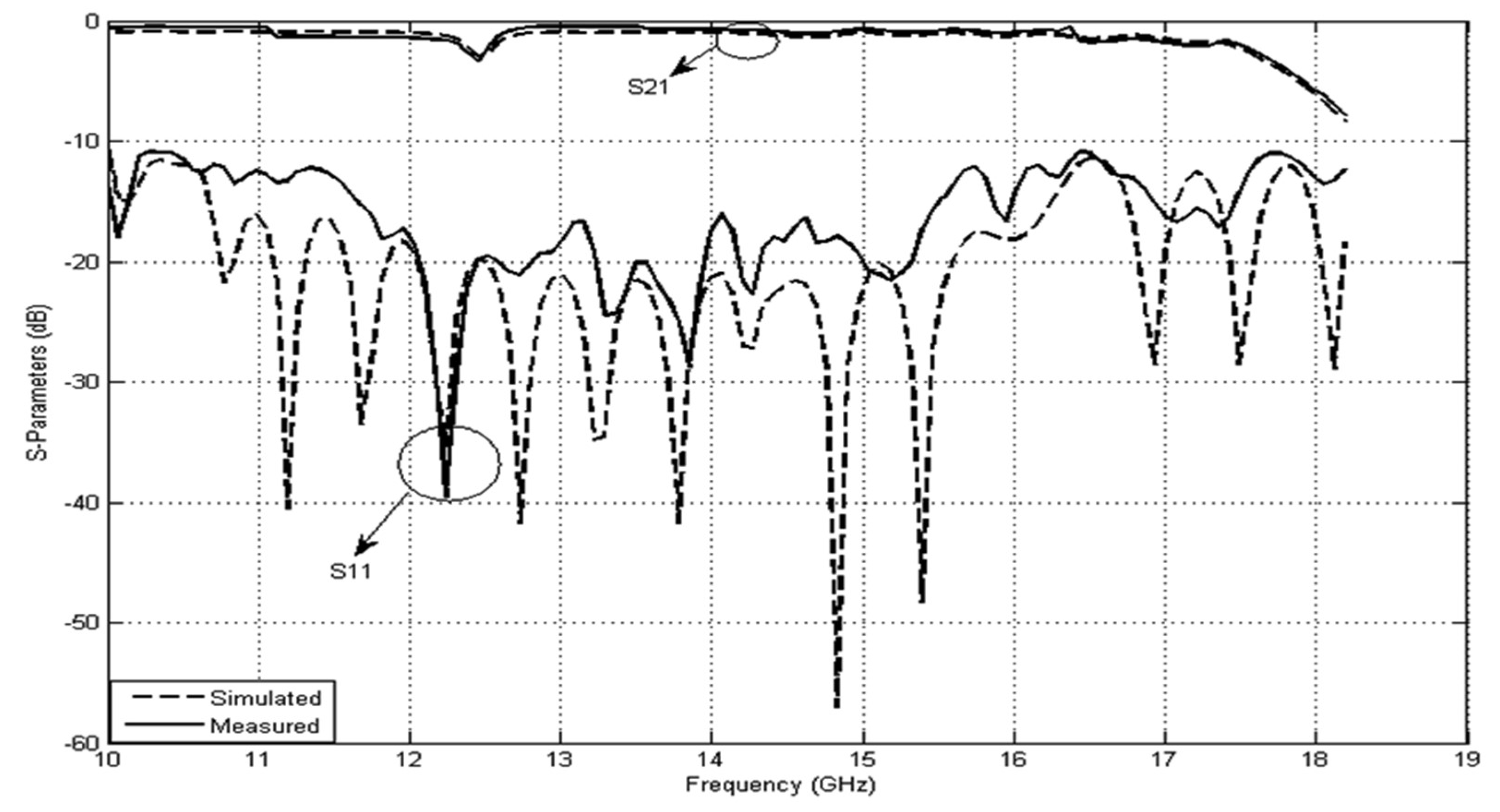
Figure 7.
Simulated and measured radiation patterns (y-z plane) for proposed SIW LWA.
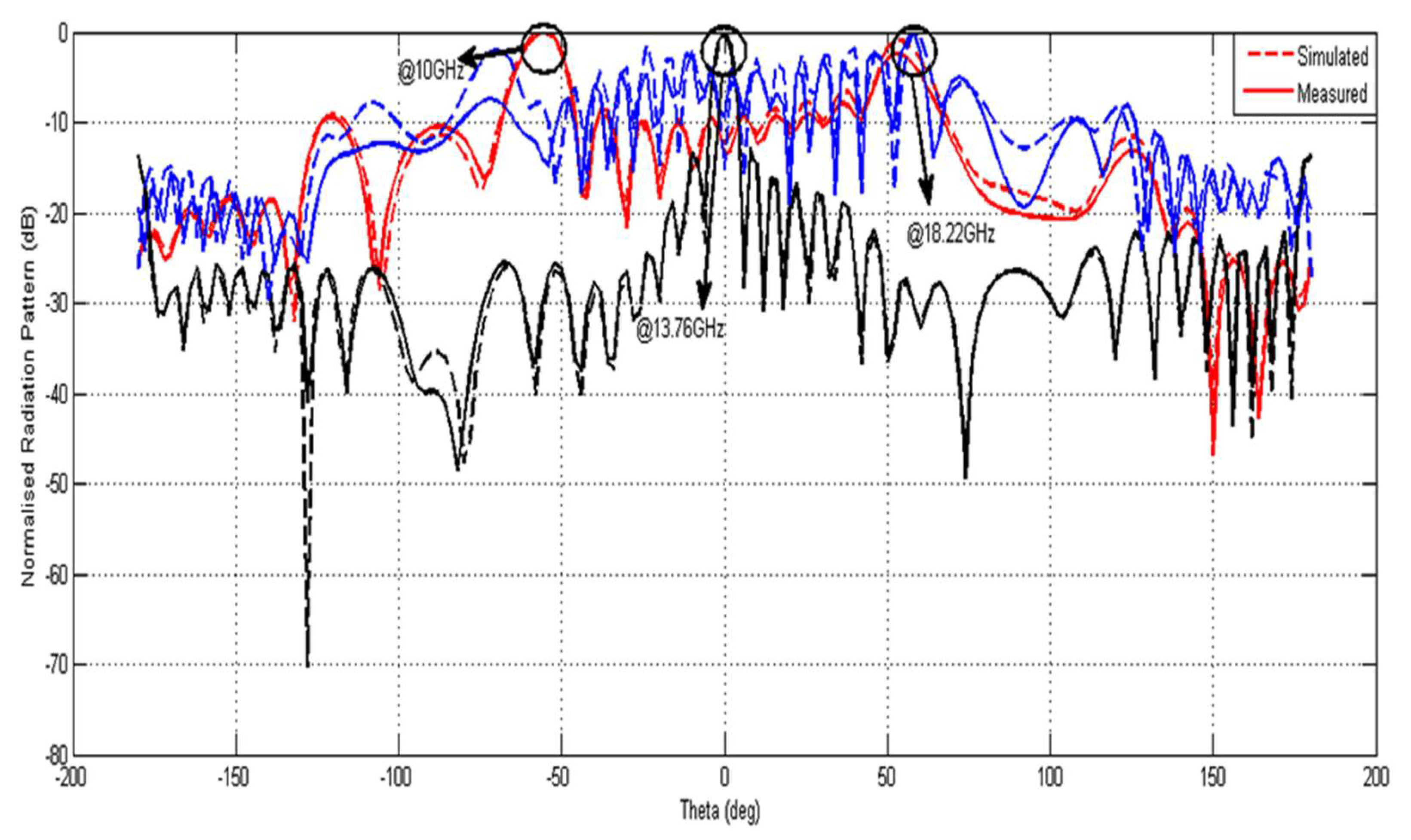
Figure 8.
SIW LWA measurement setup for far field radiation patterns.

Figure 9.
Radiation angles for SIW LWA.
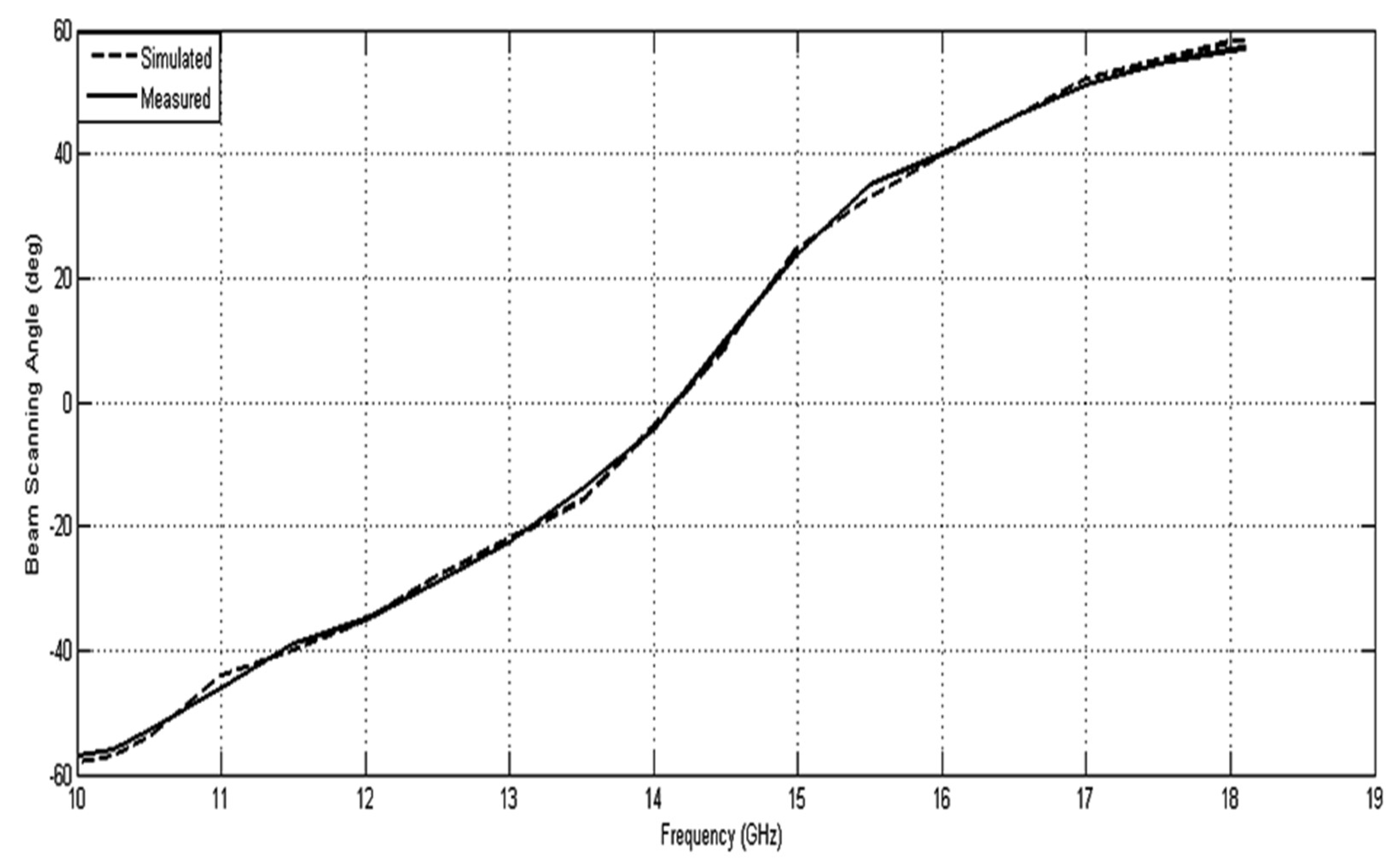
Figure 10.
Simulated and measured gain patterns for SIW LWA.

Table 1.
Parameters for unit cell.
| Parameters | Values |
|---|---|
| W | 16 mm |
| Weff | 14 mm |
| P | 14.7 mm |
| A | 5.5 mm |
| B | 0.8 mm |
| C | 1.5 mm |
| S | 2 mm |
| D | 1 mm |
Table 2.
Shows a comparison to other reported designs.
| Ref. | Type of Antenna | Length of Radiator | Scanning Frequency Range (GHz) | Backward to Forward Beam Scanning | Peak Gain |
|---|---|---|---|---|---|
| [6] | PSIW-LWA ) | ~7 | 9 to 14 | Yes (−40° to +35°) | ~12 dBi |
| [17] | Multilayered CRLH SIW PLWA ) | ~6 | 8 to 13 | Yes (−66° to +78°) | ~9 dBi |
| [18] | Microstrip Based CRLH PLWA ) | NA | 6.4 to 7.6 | Yes (−45° to +37°) | ~10 dBi |
| [19] | Microstrip Periodic LWA ) | ~6 | 7.2 to 8.2 | Yes (−25° to +15°) | ~12 dBi |
| [20] | Periodic RSIW LWA ) | NA | 8 to 12 | Yes (−35° to +35°) | ~11 dBi |
| [21] | Microstrip PLWA ) | ~30 | NA | Yes (NA) | ~21 dBi |
| [22] | PLWA Based on Goubau line ) | ~7 | 9 to 13 | Yes (−13° to +19°) | ~11.5 dBi |
| [23] | CRLH Based HMSIW LWA ) | ~5 | 8.5 to 12 | Yes (−35° to +37°) | ~10 dBi |
| [24] | Periodic HMSIW LWA ) | ~8 | 10 to 14 | Yes (−27° to +23°) | ~11.5 dBi |
| [25] | CRLH HMSIW LWA ) | ~4.85 | 13.5 to 17.8 | Yes (−66° to +20°) | ~16 dBi |
| [26] | Periodic SIW LWA ) PHMSIW LWA ) | ~6.84 ~6.84 | 10.17 to 16.3 10 to 16.5 | Yes (−38° to +22°) Yes (−50° to +26°) | ~11 dBi ~12 dBi |
| This work | SIW LWA ) | ~6.84 | 10 to 18.22 | Yes (−58° to +59°) | ~14.5 dBi |
Disclaimer/Publisher’s Note: The statements, opinions and data contained in all publications are solely those of the individual author(s) and contributor(s) and not of MDPI and/or the editor(s). MDPI and/or the editor(s) disclaim responsibility for any injury to people or property resulting from any ideas, methods, instructions or products referred to in the content. |
© 2023 by the authors. Licensee MDPI, Basel, Switzerland. This article is an open access article distributed under the terms and conditions of the Creative Commons Attribution (CC BY) license (https://creativecommons.org/licenses/by/4.0/).
Share and Cite
MDPI and ACS Style
Arya, V.; Garg, T.; Al-Khafaji, H.M.R. High Gain and Wide-Angle Continuous Beam Scanning SIW Leaky-Wave Antenna. Electronics 2023, 12, 370. https://doi.org/10.3390/electronics12020370
AMA Style
Arya V, Garg T, Al-Khafaji HMR. High Gain and Wide-Angle Continuous Beam Scanning SIW Leaky-Wave Antenna. Electronics. 2023; 12(2):370. https://doi.org/10.3390/electronics12020370
Chicago/Turabian StyleArya, Vivek, Tanuj Garg, and Hamza Mohammed Ridha Al-Khafaji. 2023. "High Gain and Wide-Angle Continuous Beam Scanning SIW Leaky-Wave Antenna" Electronics 12, no. 2: 370. https://doi.org/10.3390/electronics12020370
Note that from the first issue of 2016, this journal uses article numbers instead of page numbers. See further details here.