
Overview on Battery Charging Systems for Electric Vehicles

Department of Information Engineering, University of Pisa, Via Girolamo Caruso n.16, 56100 Pisa, Italy
*
Author to whom correspondence should be addressed.
Electronics 2023, 12(20), 4295; https://doi.org/10.3390/electronics12204295
Submission received: 28 September 2023
/
Revised: 12 October 2023
/
Accepted: 15 October 2023
/
Published: 17 October 2023
Abstract
:Catalyzed by the increasing interest in bi-directional electric vehicles, this paper delves into their significance and the challenges they encounter. Bi-directional electric vehicles not only serve as transportation but also function as essential electricity resources. Central to this energy revolution are On-Board Chargers (OBCs), which are pivotal in converting alternating (AC) energy into direct (DC) energy and vice versa. In this context, we explore the various circuit architectures of OBCs employed in bi-directional electric vehicles. We delve into the intricacies of rectifiers, switching converters, and the application of advanced control and filtering technologies. Our analysis extends to the implications of these circuit architectures on aspects such as voltage regulation capability, energy efficiency, and thermal management. Furthermore, we address the broader significance of these developments in the integration of bidirectional systems, which are driving advances in circuit architectures to better harness the energy flexibility of electric vehicles. We emphasize the critical role of bi-directional electric vehicles in the transition toward a smart and sustainable energy grid. To enhance accessibility for a diverse readership, we will provide concise definitions or explanations for technical terms used throughout the paper, ensuring that our work is approachable even for those who may not be experts in the field.
Keywords:
on-board chargers; off-board chargers; power electronics; power converters; AC/DC; DC/DC; automotive1. Introduction to Battery Chargers for EV
Charging systems for hybrid and electric vehicles are essential for powering the batteries of such vehicles, enabling them to operate efficiently. These systems can be divided into two main categories: off-board charging systems and on-board charging systems [1,2] (see Figure 1).
Below we provide an overview of both types of systems.
- Off-Board Charging Systems:
- −
- Public Charging Stations: These are publicly accessible charging stations and are often located in places such as gas stations, public parking lots, shopping malls, and other public areas. Public charging stations usually provide high-power direct current (DC) charging and low-power alternating current (AC) charging [3,4].
- −
- −
- −
- On-Board Charging Systems:
- −
- On-Board Charger: Most hybrid and electric vehicles are equipped with an on-board charger that allows the vehicle to be connected to an external power source, such as a household outlet or a public charging station. This charger converts electricity into direct current to recharge the battery [13,14,15].
- −
- Recharging Connector: Every electric vehicle has a charging connector that connects to the charging station. There are various types of connectors, including the CCS (Combined Charging System) connector, the CHAdeMO connector [16], and the Type 2 connector (IEC 62196) [17]. Compatibility between the vehicle and the charging station depends on the type of connector used.
- −
- Recharge Management Systems: Some electric vehicles are equipped with advanced charging management systems that allow drivers to schedule charging according to their schedules or take advantage of cheaper energy rates. These systems can also optimize charging to preserve battery life [18].
- −
In general, the availability of charging stations, charging power, and connector compatibility are important factors influencing the charging experience for hybrid and electric vehicle owners. The continued expansion of public charging infrastructure and the evolution of charging technologies are contributing to the increasing viability of electric vehicles.
In the context of the evolution of sustainable mobility, it is critical to understand the differences and evaluate the advantages and disadvantages of off-board and on-board charging systems for hybrid and electric vehicles. Off-board charging stations, such as public charging stations, offer the convenience of fast charging speed, which is ideal for long-distance travel and situations where fast charging is needed. These stations are increasingly available in urban areas and along highways, increasing accessibility to electric vehicles. In addition, many of these stations are compatible with a wide range of vehicles, regardless of model or manufacturer. Some of them also provide high-power charging, allowing substantial charging in very little time. However, there are also disadvantages to consider, such as the user fees associated with certain public stations, which can increase total charging costs compared to home charging. In addition, crowding and limited availability in some areas can cause inconvenience to drivers. On the other hand, on-board charging at home offers maximum convenience and keeps the vehicle always ready for use, eliminating the need to travel to public charging stations. The ability to schedule charging overnight by taking advantage of cheaper energy rates helps reduce operating costs. In addition, the lack of user fees makes this option cheaper in the long run. However, on-board charging at home has some limitations, including a more limited charging speed than public stations or fast charging solutions. This could be problematic for those who require fast charging. In addition, mobility is limited to locations where a dedicated charging station has been installed, and initial installation can incur significant costs, especially if changes have to be made to the existing electrical system. In conclusion, the choice between off-board and on-board charging systems is influenced by the individual needs of drivers. Often, the best approach is to use a combination of both systems to maximize convenience and reduce the cost of operating hybrid and electric vehicles.
In Table 1, we provide a direct comparison between off-board and on-board charging systems for electric vehicles. This comparison is crucial for understanding the choices that electric vehicle drivers must make when it comes to recharging their vehicles. Below, we discuss the key points presented in the table.
Off-board systems, including public charging stations, rapid charging stations, and wireless charging systems, offer a wide presence of stations in urban areas and along highways. These systems are known for their ability to provide fast charges and are ideal for long-distance travel. However, they may involve higher costs due to usage fees at some stations and can be affected by congestion in certain areas. On the other hand, on-board systems primarily rely on home charging stations. They offer maximum convenience, allowing drivers to recharge their vehicles directly at home. This approach eliminates usage fees and provides the flexibility to schedule charging during cost-effective energy rate hours. However, charging is slower compared to high-power public stations, which could be a concern for those in need of fast charging. Additionally, it requires the installation of a dedicated home charging station, incurring associated costs. The comparison between these two systems is vital for electric vehicle drivers as it will significantly impact their charging experience and associated costs. The choice between off-board and on-board systems will depend on individual driver needs and the charging conditions available in their region.
2. On-Board Chargers for HV/EV Charging Systems
2.1. Motivation to Move on OBCs
On-board chargers (OBCs) represent a dominant technology trend over off-board chargers in electric and hybrid vehicles due to a number of key advantages. First, their direct integration into vehicles offers significant convenience to users. It is no longer necessary to carry an external charger or to search for dedicated charging stations. The ability to charge directly from a standard power outlet, such as the one in one’s home, greatly simplifies the daily lives of motorists. In addition, OBCs can be designed and optimized specifically to suit the needs of the vehicle’s battery. This results in greater efficiency during the charging process. OBCs can deliver more consistent and controlled charging power than off-board chargers, which must be designed to fit a variety of vehicles. The integration of OBCs into vehicles also enables more direct and sophisticated communication. Many OBCs are equipped with two-way communication systems that enable the vehicle to interact with the power grid and charging infrastructure. This paves the way for advanced features, such as scheduling charging time to take advantage of low energy rates or managing power in response to grid needs. From a size and weight perspective, integrated OBCs take up less space than external chargers and can contribute to overall weight savings in vehicles. In terms of safety, OBCs can be designed with advanced protection systems to ensure the safety of the vehicle and the charging system. These systems include short-circuit detection, temperature monitoring, and overload protection. Finally, there is a trend toward the standardization of OBCs. Automakers and industry organizations are working to establish common standards, thereby simplifying the production and use of electric and hybrid vehicles. In summary, on-board chargers offer a convenient, efficient and integrated solution for charging electric and hybrid vehicles. Although they can be complemented by external charging stations for longer trips or public needs, their predominant role in meeting daily charging needs is a major step forward in the transition to electric mobility.
2.2. Standards and Classification
In electric vehicles, On-Board Charger (OBC) device connectors play a crucial role in battery charging. There are different types of connectors around the world, each with its own specific characteristics and applications. The J1772 (Type 1) connector is commonly used in the United States, Canada, and some other regions. However, its charging speed is limited compared to newer standards and is associated with vehicles such as the Nissan Leaf and Chevrolet Volt, both made in the United States. Tesla uses a proprietary connector, known as the Tesla Connector, which offers high charging powers, greatly accelerating the charging of Tesla vehicles, including the Model S, Model 3, Model X, and Model Y. However, this standard is exclusive to Tesla vehicles and is not compatible with those of other manufacturers. In Japan and some regions of the world, the CHAdeMO connector is common and offers fast DC charging. It is often associated with vehicles such as the Nissan Leaf, Mitsubishi i-MiEV, and Kia Soul EV. The Combo Charging System (CCS) connector has been increasingly adopted in Europe and North America [22].
It offers the versatility of supporting both DC and AC charging and is associated with vehicles from brands such as BMW, Volkswagen, Ford, Audi, and others. In Europe, the Type 2 connector (IEC 62196) is widely used for AC charging. It is associated with vehicles such as the Renault Zoe and BMW i3, among others. Although it does not support DC charging, it is well established in Europe and offers reliable charging. CCS (Type 2) is an extension of the CCS standard used in Europe, which also includes AC charging. This standard is used by many European automakers, including BMW, Volkswagen and others, for vehicles with DC and AC charging capabilities. In China, the GB/T connector (GBT 20234) is used as a national standard and is compatible with DC and AC charging. It is associated with vehicles produced by companies such as BYD and NIO. The choice of connector depends on geographic region, automaker, and preferred charging strategy, as described in Figure 2. Global standards, such as CCS, are becoming more common to increase compatibility between vehicles and the availability of charging stations. However, it is important to consider connector compatibility with the vehicle and local infrastructure when making the choice of an electric vehicle [23]. On-board chargers (OBCs), used in electric and hybrid vehicles, can be classified according to the power levels they are capable of delivering. These power levels are critical in determining the charging characteristics of a vehicle. Let us now look at a description of the voltage and power levels typically involved.
Standard power levels include “Level 1” and “Level 2”. Level 1 is characterized by single-phase voltages of 120 V (in the United States) or 230 V (in Europe) and can deliver a power output of about 1.3–1.9 kW (typically). This level is commonly used for home charging, especially overnight, and is suitable for vehicles with smaller batteries. The charging time for Level 1 chargers can vary depending on the vehicle’s battery capacity, but it typically takes several hours to fully recharge a vehicle from near empty to full. Level 2, on the other hand, operates on single-phase voltages of 240 V (in the United States) or 230 V (in Europe) and can deliver a larger power, generally ranging from 3.7 kW to 22 kW, depending on whether the device is in a single-stage configuration or two/multiple-stage configuration, respectively. This level is the most common for home and public charging and is suitable for most electric and hybrid vehicles. Charging times at Level 2 are significantly faster than Level 1, and many vehicles can be fully recharged overnight or within a few hours, depending on battery capacity. As for high power levels, we find “Level 3” or “DC Fast Charging”. This level involves much higher voltages and direct DC conversion. Voltages can vary widely, but can be as high as 600 V or more, with powers exceeding 50 kW or even 350 kW (as in Tesla superchargers) [13,24]. Level 3 chargers provide exceptionally fast charging times. Depending on the specific charger and vehicle, some Level 3 chargers can replenish a significant portion of the battery’s capacity in as little as 30 min to an hour. This level is designed to allow much faster recharging than the lower levels and is used in fast-charging stations along highways and in public areas (see Figure 3). The choice between single-phase and three-phase systems depends mainly on the available supply voltage and the specifications of the electric vehicle. Single-phase systems use a single phase of alternating current (AC) and are the most common type for home charging. They are suitable for single-phase voltages of 120 V or 230 V and are a convenient solution for home charging, offering relatively faster charging times than Level 1. On the other hand, three-phase systems use three phases of AC and deliver significantly more power than single-phase systems. These systems are typically used for public and commercial charging, enabling faster and more efficient recharging. However, they require a three-phase power grid and often need to be installed in specific locations. The choice will depend on the availability of the supply voltage, the specific needs of the vehicle, and the desired charging times [25,26,27].
2.3. Configurations and Main Components of an OBC
A charging system for electric and hybrid vehicles consists of a number of key components that work together to ensure efficient and safe charging. At the core of this system is the on-board charging (OBC) system, which is a crucial element in the electric mobility ecosystem. In electric vehicles, On-Board Chargers (OBCs) play a crucial role in battery charging. There are three main types of OBC configurations—one-stage, two-stage, and multi-stage—each with specific advantages and applications based primarily on the required charging power. The one-stage configuration is the simplest and most cost-effective. A single AC/DC converter converts power from the electric grid to direct current (DC) for battery charging. It is suitable for electric vehicles with moderate charging powers, typically up to 22 kW. This configuration is ideal for home charging and vehicles with moderate capacity batteries. The two-stage configuration is more complex and uses two AC/DC converters: one for charging at low powers and one for charging at high powers, often from 22 kW up to 350 kW or more. It is ideal for vehicles that require a wide range of charging powers. It offers greater flexibility and supports high-power DC charging, greatly reducing charging time. The multi-stage configuration is the most advanced and uses three or more AC/DC converters. It is designed to handle extremely high charging powers, such as those above 350 kW, making ultra-rapid charging possible. This configuration is critical for commercial vehicles and high-power public charging stations. However, it is also the most complex and expensive to implement. In summary, the choice of OBC configuration depends mainly on the power requirements of electric vehicles. Single-stage configurations are suitable for moderate power and home charging, while two-stage and multi-stage configurations are essential for high-power and ultra-rapid charging, often associated with commercial vehicles or public charging stations. Complexity and cost increase with the number of stages, so the choice is driven by the need to support specific charging powers [28,29,30,31,32]. Make reference to Figure 4 for the general configurations of an OBC system.
A rectifier is a key component in electrical conversion systems and is often the first conversion stage in any On-Board Charger (OBC) configuration in electric vehicles. Its main function is to convert electrical energy from an initial form, usually in the form of alternating voltage (AC), to a usable form, namely direct voltage (DC).
This conversion is essential to enable the effective charging of electric vehicle batteries. There are two main types of rectifiers: passive rectifiers and active rectifiers, each of which has a different operating principle.
- Passive Rectifier: A passive rectifier uses passive components such as diodes to convert AC to DC. The diode is the key component in a passive rectifier. The operation of a passive rectifier occurs in two phases:
- −
- Half-Wave Phase (Half-Wave Rectification): In this phase, the diode allows the positive voltage from the input AC to pass through, while blocking the negative voltage. This means that only half of the AC wave is transmitted to the output DC. This is an inefficient process since half of the energy is discarded.
- −
- Full-Wave Phase (Full-Wave Rectification): In this phase, two diodes are used to capture both the positive and negative parts of the AC wave. This results in more efficient conversion, but it is still imperfect because the AC wave is split into two separate halves and the result is a pulsing DC wave.
- Active Rectifier: An active rectifier uses transistors or controlled semiconductor devices to convert AC to DC more efficiently than a passive rectifier. There are two main types of active rectifiers: bridge rectifiers and controlled rectifiers.
- −
- Bridge Rectifier: This type of active rectifier uses four diodes in a bridge circuit to convert AC to DC. The operation is similar to that of the passive full-wave rectifier, but with four diodes instead of two. This allows a more complete conversion of AC to DC and is the most common type of rectifier used in domestic applications.
- −
- Controlled Rectifier (Controlled Rectifier): This type of rectifier uses controlled transistors or GTO to adjust the output voltage as needed. These devices can be turned on or off in a controlled manner, allowing the more precise and flexible conversion of AC to DC. Controlled rectifiers are used in applications where accurate voltage control is needed, such as in switching power supplies.
Main differences between passive and active rectifiers:
- i
- Efficiency: Active rectifiers are generally more efficient than passive rectifiers because they reduce power losses.
- ii
- Control: Active rectifiers allow more control over the output voltage.
- iii
- Applications: Passive rectifiers are suitable for simple applications, while active rectifiers are preferred when more advanced and precise power conversion is required.
In general, the choice between a passive and an active rectifier depends on the specific needs of the application and the requirements for efficiency and accuracy. DC/DC converters play a crucial role in electric vehicle OBC devices, enabling the efficient management of electrical energy. Their main purpose is to regulate the incoming direct current (DC) voltage to the DC voltage required to charge the battery or power other vehicle systems. These converters are often designed to operate in different modes depending on the specific needs of the vehicle and context of use. Some of the most common modes include:
- i
- Buck Mode: In this mode, the converter reduces the DC input voltage to a lower level of DC output voltage. This operation is useful when it is necessary to lower the voltage of the traction battery to power lower voltage devices, such as the cooling system or the control circuit.
- ii
- Boost mode: Boost mode is the opposite of Buck mode. In this case, the converter boosts the DC input voltage to a higher level of DC output voltage. This is crucial when you want to charge the battery at a higher voltage than that provided by the mains.
- iii
- Buck–Boost Mode: This mode allows you to adjust both higher and lower voltages than the input voltage. It is useful when maximum flexibility in power management is required.
- iv
- Isolation Mode: Some DC/DC converters are designed to provide electrical isolation between the input and output. This is important to ensure safety and protection of vehicle circuits.
- v
- Regulation Mode: DC/DC converters can also be used to adjust the output voltage according to specific battery charging requirements, ensuring that the battery receives the correct voltage and current during the charging process.
DC/DC converters in OBC devices are often designed to be highly efficient to minimize energy losses during conversion. This is crucial to maximizing the range of electric vehicles and minimizing operating costs. In general, DC/DC converters play a key role in the electric vehicle ecosystem, helping to ensure the reliable and efficient operation of OBC devices as well as optimized power management.
Electromagnetic Interference (EMI) filters are essential components in On-Board Charger (OBC) devices in hybrid and electric vehicles. Their main function is to manage and reduce electromagnetic interference generated during the electric charging process. During the charging process, current and voltage fluctuations can occur that generate electromagnetic interference. EMI filters are designed to capture this electromagnetic interference and conduct it to ground or absorb it, thus preventing it from spreading into the power grid or interfering with other electronic devices. Regulatory bodies and electromagnetic compatibility (EMC) standards place restrictions on the level of electromagnetic interference a device can emit. Installing EMI filters helps ensure that the OBC device complies with these regulations, avoiding legal penalties and ensuring safe and efficient operation. OBC devices contain sensitive electronic components, such as control circuits and power devices. Electromagnetic interference can damage or disrupt the proper functioning of these components [33,34,35]. EMI filters protect such components from harmful interference. Likewise, EMI filters also prevent external interference, such as radio waves or other sources of interference, from affecting the operation of the OBC device. EMC regulations, such as CISPR (Commission Internationale de l’Éclairage Special Committee on Radio Interference) and FCC (Federal Communications Commission), impose limits on electromagnetic emissions from electrical and electronic devices. OBC devices must be designed in accordance with these regulations to ensure electromagnetic compatibility with other electronic devices and to avoid unwanted interference [36,37,38]. In addition, regulations may vary from region to region. For example, in Europe, CE marking is a requirement that indicates compliance with EMC regulations. EMI filters are critical components in hybrid and electric vehicle OBC devices because they help ensure that the charging process is efficient, safe, and complies with EMC regulations. Their presence is critical to protect electronic components, prevent external interference, and ensure compliance with design regulations.
EMI filters in On-Board Charger (OBC) devices in hybrid and electric vehicles can adopt different circuit topologies to reduce electromagnetic interference. These topologies include the (pi)-shaped EMI filter, T-shaped EMI filter, low-pass EMI filter, and active EMI filter. The pi-shaped EMI filter uses passive components such as inductors, capacitors and resistors to create a pi-shaped configuration. This type of filter is effective in suppressing low-frequency interference and is often used in battery electric vehicle (BEV) OBC devices. The T-shaped EMI filter is similar to the filter but has a T-shaped configuration. This topology is suitable for suppressing interference at medium and high frequencies and is ideal for applications where interference may occur over a wider range of frequencies. The EMI low-pass filter is designed to allow lower frequencies to pass through while attenuating higher frequencies. It uses components such as inductors and capacitors to create a barrier at high frequencies, thereby reducing interference at higher frequencies. This type of filter is commonly used in OBC devices for electric vehicles to limit high-frequency interference. Finally, the active EMI filter varies in its circuit topology depending on the specific design. These filters use operational amplifiers, transistors and other active components to counteract electromagnetic interference. They can suppress interference at varying frequencies and offer greater flexibility in interference management. The choice of circuit topology depends on the EMI characteristics present in the specific application and the filtering requirements. In addition, the EMI filter design takes into account the frequency of interference, EMC regulations, and OBC system requirements. Each topology has its optimal applications and must be selected according to the design specifications to ensure effective suppression of electromagnetic interference (see Figure 5). In addition to the power conversion components, the OBC system is equipped with a number of monitoring and control features. These include sensors that constantly monitor charging conditions, ensuring that the process occurs safely and efficiently. The OBC system can also communicate with the power grid or charging station to adjust power according to specific needs, thus contributing to grid management. Finally, OBC systems are designed with a focus on safety. They feature multiple protections, including temperature monitoring, overload protection, short-circuit protection, and other safety measures to ensure a safe charging experience for users and protection of the vehicle. In summary, the on-board charging system for electric and hybrid vehicles is a complex system that integrates several components, including the inverter, DC–DC converters, and a number of safety and control measures. These components work together to ensure efficient, safe and controlled charging directly from the vehicle, thus helping to promote the adoption of electric and hybrid vehicles.
2.4. Trend in Switching Components Technology
Wide bandgap (WBG) semiconductors, including materials like gallium nitride (GaN) and silicon carbide (SiC), have emerged as contenders offering superior performance and enhanced power efficiency when compared to traditional silicon devices. Their advantages extend to high-temperature operation, making them increasingly attractive across a spectrum of applications [39]. However, it is essential to acknowledge that WBG devices often come with a higher price tag. This cost differential can be attributed, at least in part, to the ongoing refinement of WBG manufacturing processes—a typical evolution in emerging technologies. Additionally, SiC’s inherent physical properties pose challenges, making the process of cutting, grinding, and polishing SiC wafers more time-consuming and expensive relative to silicon [40]. In the realm of power switching and supply applications, the decision between WBG alternatives and conventional silicon devices is far from one-size-fits-all. The choice hinges on the specific requirements and business considerations unique to each use case. Although some design engineers might initially hesitate to embrace WBG technology, it is crucial to recognize that the benefits often outweigh any potential drawbacks [41].
While silicon has dominated the power electronics market for decades, the growing interest in Wide Bandgap (WBG) alternatives cannot be ignored. These WBG options deliver compelling efficiency advantages, particularly in applications striving to maximize power utilization, such as electric vehicles and renewable energy generation [42]. However, the heightened cost associated with WBG power semiconductors may deem them less suitable for certain applications, such as low-cost consumer power supplies. In such scenarios, the efficiency gains achieved by adopting SiC or GaN devices might not justify the additional expenditure [43]. Notably, the improved efficiency characteristic of WBG devices translates into reduced heat dissipation. This, in turn, can facilitate advancements in mechanical and thermal design, potentially resulting in more compact product designs. Furthermore, SiC boasts the ability to operate effectively at higher temperatures (175 to 200 °C) compared to silicon, potentially reducing the need for supplementary cooling mechanisms like heat-sinks. Such attributes hold significant appeal across various automotive and industrial applications [44]. Figure 6 visually illustrates the typical suitability of various device types based on voltage and switching frequency considerations. In broad terms, silicon MOSFETs and IGBTs excel in lower-frequency applications, while GaN and SiC devices shine in higher-frequency scenarios. The abbreviation FOM denoting figure of merit signifies that multiple semiconductor technologies could prove suitable for applications in this realm, underscoring the necessity for precise comparisons to determine the optimal choice in each specific application (see Figure 7). In summary, the selection between WBG and silicon devices is influenced by factors like switching frequency, power levels, cost considerations, and power source. Typically, silicon IGBTs shine when the switching frequency falls below approximately 20 kHz, or when power levels exceed 3 kW. They also offer an economically attractive solution when low-cost deployment or three-phase grid compatibility is essential. However, the trajectory of technology is moving towards embracing SiC and GaN devices, fueled by their superior efficiency, enhanced power density, and reduced cooling requirements [45]. Modern trends indicate SiC’s increasing prevalence in high-power and extra-high-voltage applications, where it can compete effectively with IGBT transistors. GaN devices are gaining ground in power electronics applications, challenging established semiconductors like Si LDMOS MOSFETs, super-junction MOSFETs, and IGBTs. SiC MOSFETs are making inroads in electrified vehicles, including on-board chargers, due to their high efficiency, reduced cooling needs, and impressive power density. GaN devices are predicted to enter the OBC and DC–DC converter markets ahead of the inverter market due to their lower power and voltage requirements [46]. SiC devices find favor in various electrified vehicle applications, including electric power drives and traction inverters [47,48,49,50,51,52,53,54,55,56,57,58], power management DC–DC converters and fast-charging OBCs [59,60,61,62,63,64]. The prevalence of SiC and GaN devices in power electronics is on the rise, driven by their high efficiency, remarkable power density, and reduced cooling demands. The cost difference between Wide Bandgap (WBG) devices, such as silicon carbide (SiC) and gallium nitride (GaN), and traditional silicon-based devices has a significant impact on the electric vehicle and renewable energy generation industries. This difference can influence several aspects, including efficiency, performance, and overall system costs. Here is a more detailed discussion on this topic:
- Impact on electric vehicles:
- −
- Efficiency and range: WBG devices, such as SiC and GaN, offer higher energy efficiency compared to traditional silicon-based devices. This means that electric vehicles (EVs) equipped with these components can achieve greater range with the same amount of stored energy in the battery. This is a significant advantage for the automotive industry, as EVs can cover longer distances between charges, improving their appeal to consumers.
- −
- Faster charging times: The higher efficiency of WBG devices also allows for reduced charging times. This is essential for making EV charging faster and more convenient, bringing the charging experience closer to that of traditional fueling. Reduced charging times could contribute to increased EV adoption.
- −
- Battery lifespan: The improved energy efficiency and management offered by WBG devices can contribute to a longer battery lifespan in electric vehicles. This would reduce long-term costs for EV owners and enhance sustainability.
- Impact on renewable energy generation:
- −
- Grid integration: The enhanced efficiency of WBG devices is a significant advantage in wind and solar energy generation, as it enables the better integration of renewable energy sources into existing electrical grids. The ability to convert and transmit energy more efficiently helps reduce energy losses and ensures that more renewable energy can be utilized in the grid.
- −
- Solar and wind inverters: SiC and GaN are widely used in inverters for solar and wind energy. These inverters convert energy generated by solar panels or wind turbines into usable electricity. The efficiency and ability to handle higher currents and voltages offered by SiC and GaN are critical for the effectiveness of these systems.
- Specific applications and sectors:
- −
- Electric vehicles: Beyond the automotive industry, WBG devices are used in other transportation applications, such as high-speed trains and heavy commercial vehicles. These sectors benefit from the higher efficiency of WBG for improved performance and energy savings.
- −
- Power electronics: SiC and GaN are used in inverters, DC–DC converters, and power regulators not only in electric vehicles but also in power electronics equipment in general. These devices improve the efficiency and performance of such systems.
- −
- Industrial applications: Industrial sectors such as automation and robotics benefit from the use of WBG devices to enhance the efficiency and precision of machines.
- −
- Medical technology: SiC and GaN devices are used in medical applications, such as magnetic resonance imaging systems and imaging equipment, improving efficiency and image quality.
In summary, the cost difference between WBG devices and silicon-based ones has a significant impact on the electric vehicle and renewable energy generation industries, improving efficiency, performance, and the attractiveness of these technologies. The increasing adoption of SiC and GaN devices in various applications is contributing to a significant transformation in key sectors and opening new opportunities in future markets.
3. AC/DC Converters for OBCs
Bidirectional active rectifiers are the current trend in AC/DC conversion for electric vehicle applications, and this can be justified by the following reasons:
- Efficiency: Bidirectional active rectifiers with power factor correction are more efficient than other types of rectifiers, such as passive rectifiers, because they reduce the amount of reactive power that is drawn from the AC power source and improve the power factor.
- Weight, volume, and cost: Bidirectional converters are preferred for practical applications because they have less weight, volume, and cost, as well as better component integration.
- Regenerative braking: Bidirectional converters are good for applications like the regenerative braking of vehicles, where power is given to the wheels of vehicles.
- Easy control and structure: Bridge-less PFC with active MOSFET is one of the most popular bidirectional rectifiers because of its easy control and structure.
- High voltage conversion levels: Bidirectional DC–DC converters ensure high voltage conversion levels, minimize voltage stress on semiconductor devices, and maintain a high power factor.
Overall, bidirectional active rectifiers are the current trend in AC/DC conversion for electric vehicle applications due to their efficiency, cost-effectiveness, and suitability for regenerative braking and high voltage conversion levels [65]. A bidirectional active rectifier is a device that can convert AC power to DC power and vice versa, allowing for bidirectional power flow. In the context of on-board chargers in electric and hybrid vehicles, bidirectional active rectifiers are used to convert AC power from the grid to DC power to charge the vehicle’s battery, as well as to convert DC power from the battery to AC power to power the vehicle’s electric motor. Power factor correction (PFC) is an important aspect of bidirectional active rectifiers, as it helps to improve the efficiency of the conversion process. PFC is a technique used to ensure that the current drawn from the AC power source is in phase with the voltage, which reduces the amount of reactive power that is drawn from the source and improves the power factor [66]. There are two types of PFC: passive and active. Passive PFC uses a passive component, such as a capacitor or inductor, to correct the power factor. Active PFC, on the other hand, uses a control circuit to actively shape the input current waveform to be in phase with the input voltage waveform. In bidirectional active rectifiers, active PFC is typically used to achieve high power factor correction. An active PFC circuit is placed between the diode bridge and the isolated DC/DC converter, and it shapes the input current waveform to be in phase with the input voltage waveform. There are several types of bidirectional active rectifiers used in on-board chargers in electric and hybrid vehicles, but the most used are as follows [67]:
- Boost type bidirectional AC/DC rectifier with active PFC: This type of rectifier uses a boost converter to achieve bidirectional power flow and active PFC to improve the power factor.
- Single-phase bidirectional rectifier with power factor correction: This type of rectifier uses a bi-directional neutral point clamped AC/DC converter with the functions of being a power factor corrector and an active filter.
- Single-stage three-phase rectifier with high-frequency isolation and power factor correction: This type of rectifier uses a single-stage three-phase rectifier with high-frequency isolation, power factor correction, and bidirectional power flow.
Overall, bidirectional active rectifiers with power factor correction are an important component of on-board chargers in electric and hybrid vehicles, as they allow for efficient bidirectional power flow between the vehicle’s battery and the grid.
3.1. Interleaved Boost PFC
Interleaved Boost Power Factor Correction (PFC) is a technique used to improve the efficiency of power conversion in AC/DC converters. Interleaved Boost PFC is a type of PFC that uses two or more interleaved boost converters to achieve high power factor correction (see Figure 8).
The advantages of Interleaved Boost PFC include:
- Increased power processing capability: Interleaved Boost PFC can increase the power processing capability of the converter by allowing for the use of multiple power switches and inductors.
- Reduced electromagnetic interference (EMI): Interleaved Boost PFC can reduce EMI by spreading the switching frequency spectrum over a wider range, which reduces the peak EMI levels [72].
The basic structure of an interleaved boost PFC converter consists of two or more interleaved boost converters connected in parallel at the input and in series at the output. The interleaved boost converters operate out of phase with each other, which reduces the input and output ripple currents and improves the power factor. The interleaved boost PFC converter can be controlled using a variety of techniques, including analog control, digital control, and mixed-signal control. The control circuit adjusts the duty cycle of the power switches to maintain a constant output voltage and improve the power factor [73,74]. Overall, Interleaved Boost PFC is an efficient and effective technique for improving the power factor correction in AC/DC converters. Its advantages include reduced inductor size, improved efficiency, increased power processing capability, and reduced EMI.
3.2. Bridgeless Totem-Pole PFC
Bridgeless Totem-Pole Power Factor Correction (PFC) is a topology commonly employed in AC/DC converters to enhance the efficiency of the power conversion process. This topology offers several notable features and applications. The primary advantage of the Bridgeless Totem-Pole PFC topology lies in its elimination of the need for a diode bridge rectifier. This elimination significantly reduces conduction losses, ultimately leading to improved overall converter efficiency. This topology achieves this by employing a totem-pole configuration of power switches (see Figure 9). This configuration allows for bidirectional power flow and simultaneously reduces the voltage stress placed on the switches, further enhancing efficiency [75,76,77].
Various power semiconductor devices can be utilized to implement the Bridgeless Totem-Pole PFC topology, including silicon MOSFETs, silicon carbide MOSFETs, and gallium nitride (GaN) devices. The control of the Bridgeless Totem-Pole PFC topology can be achieved through multiple techniques, such as analog control, digital control, and mixed-signal control. The control circuit dynamically adjusts the duty cycle of the power switches to maintain a consistent output voltage and improve the power factor [78,79]. This topology finds applications in diverse fields, including electric vehicle onboard chargers, energy storage systems, and server power supplies, showcasing its versatility and utility. The benefits of adopting the Bridgeless Totem-Pole PFC topology are numerous and include notable improvements in efficiency, a reduction in conduction losses, decreased voltage stress on the switches, and minimized electromagnetic interference (EMI) [80,81]. However, it is essential to acknowledge the challenges associated with this topology. These challenges include the complexity of the control circuit, the necessity for high-speed switching devices, and the requirement for meticulous layout and design to minimize EMI emissions. In summary, Bridgeless Totem-Pole PFC represents an efficient and effective solution for enhancing power factor correction in AC/DC converters. Its advantages, including heightened efficiency and reduced conduction losses, are coupled with some challenges, such as control circuit complexity and the demand for high-speed switching devices [82,83].
3.3. Interleaved Totem-Pole PFC
Interleaved Totem-Pole Power Factor Correction (PFC) is a topology used in AC/DC converters to improve the efficiency of the power conversion process. It is an extension of the Bridgeless Totem-Pole PFC topology that uses multiple interleaved totem-pole converters to achieve high power factor correction [84,85]. The advantages of Interleaved Totem-Pole PFC include:
- Reduced input and output ripple currents: Interleaved Totem-Pole PFC reduces the input and output ripple currents by interleaving multiple totem-pole converters, which reduces the switching losses in the power switches [86].
The basic structure of an interleaved totem-pole PFC converter consists of multiple interleaved totem-pole converters connected in parallel at the input and in series at the output (see Figure 10).
The interleaved totem-pole converters operate out of phase with each other, which reduces the input and output ripple currents and improves the power factor. The interleaved totem-pole PFC converter can be controlled using a variety of techniques, including analog control, digital control, and mixed-signal control. The control circuit adjusts the duty cycle of the power switches to maintain a constant output voltage and improve the power factor. Overall, Interleaved Totem-Pole PFC is an efficient and effective topology for improving the power factor correction in AC/DC converters. Its advantages include reduced input and output ripple currents, improved efficiency, reduced EMI, and increased power processing capability [93,94].
3.4. Three-Phase Totem Pole Active Rectifier
The three-phase totem pole active rectifier is a topology used in AC/DC converters to achieve high power factor correction and high efficiency. It is an extension of the Bridgeless Totem-Pole PFC topology that uses a totem pole configuration of power switches to achieve bidirectional power flow and reduce the voltage stress on the switches (see Figure 11).
Here are some more detailed descriptions of the three-phase totem pole active rectifier:
- The three-phase totem pole active rectifier can be implemented using various power semiconductor devices, including silicon MOSFETs, silicon carbide MOSFETs, and gallium nitride (GaN) devices. The choice of semiconductor devices depends on the specific application and the desired performance [95,96].
- The three-phase totem pole active rectifier can be controlled using various techniques, including analog control, digital control, and mixed-signal control. The control circuit adjusts the duty cycle of the power switches to maintain a constant output voltage and improve the power factor. The control circuit can also include protection features, such as overcurrent protection and overvoltage protection [97,98].
- The three-phase totem pole active rectifier can be used in various applications, including electric vehicle onboard chargers, energy storage systems, and server power supplies. The specific application determines the requirements for the power rating, the input voltage range, and the output voltage range [99,100].
- The advantages of the three-phase totem pole active rectifier include improved efficiency, reduced conduction losses, reduced voltage stress on the switches, and reduced EMI. The improved efficiency and reduced losses result from the use of the totem pole configuration and the bidirectional power flow. The reduced voltage stress on the switches results from the use of multiple power switches in series [101,102].
- The challenges of the three-phase totem pole active rectifier include the complexity of the control circuit, the need for high-speed switching devices, and the need for careful layout and design to minimize EMI. The complexity of the control circuit depends on the specific implementation and the desired performance. The need for high-speed switching devices results from the high-frequency operation of the converter.
- The design of a three-phase interleaved totem-pole PFC reference design for HEV/EV onboard charger has been implemented to achieve a efficiency at a 240-V input voltage and 6.6 kW power. The design uses three-phase interleaving and operates in continuous conduction mode (CCM) to achieve high efficiency [103,104].
The three-phase totem pole active rectifier is an efficient and effective topology for improving the power factor correction in AC/DC converters. Its advantages include improved efficiency, reduced conduction losses, and reduced voltage stress on the switches. Its challenges include the complexity of the control circuit and the need for high-speed switching devices. The specific implementation depends on the application and the desired performance. The implementation of WBG devices introduces a range of technical challenges, but these can be effectively addressed through various strategies. In applications with WBG devices, advanced control algorithms are often required to ensure efficient and precise system operation. These algorithms regulate voltage, current, and other variables, enabling dynamic control of the device. The use of dedicated micro-controllers or embedded processors allows for the efficient execution of these algorithms and adaptation to varying operating conditions. These advanced control systems can handle circuit complexity more effectively, providing the system with the flexibility needed to adapt to different applications. WBG devices such as SiC and GaN operate at very high switching frequencies. This presents some significant challenges. To address them, specialized drivers capable of handling the high switching frequencies are necessary. These drivers provide precise switching pulses and minimize switching delays. Additionally, the circuit design itself must account for the high switching speeds. This entails minimizing conductor length, reducing parasitic inductance, and using optimized circuit layouts to decrease signal propagation times. Design considerations must also encompass thermal management, as WBG devices can operate at higher temperatures. Adequate cooling is essential to prevent component damage. Another challenge associated with high switching speeds is the generation of electromagnetic interference (EMI). To mitigate this issue, appropriate EMI filters are used to ensure that the system complies with relevant EMI standards. Safety is a fundamental concern when using WBG devices, as they can handle high voltages and currents. It is essential to implement protective measures, such as current and voltage limits, to ensure safe system operation. Lastly, validation is a critical phase in managing these challenges. Developers of power systems with WBG devices conduct comprehensive testing to verify system performance and ensure it meets reliability and safety requirements. In summary, the adoption of WBG devices necessitates a holistic approach that encompasses advanced design, sophisticated control, thermal management, protection, and thorough testing. With a combination of high-quality hardware and advanced software, it is possible to successfully address the challenges related to control circuit complexity and high-speed switching in practical implementations.
4. DC/DC Converters for OBCs
DC–DC converters are essential components in automotive applications, including electric and hybrid vehicles. They are used to convert the high-voltage DC power from the battery to the low-voltage DC power required by the vehicle’s electrical system. Here is an overview of DC–DC converters used in automotive applications based on the search results:
- The power outputs of DC–DC converters range from 20 kW to 100 kW for passenger cars [111].
- The efficiency of DC–DC converters significantly impacts vehicle performance, overall efficiency, safety, and reliability [112].
- High-performance DC–DC converter systems can achieve higher power levels by enabling advanced features such as bidirectional power flow and integrated powertrain systems [113].
- The design of DC–DC converter systems requires careful consideration of factors such as power density, efficiency, and cost [114].
- The most common switching technologies used in DC–DC converters for automotive applications are IGBTs, SiC MOSFETs, and GaN devices.
- The most common DC–DC converter topologies used in automotive applications are buck, boost, and buck–boost [115].
DC–DC converters are essential components in automotive applications, including electric and hybrid vehicles. They can be isolated or non-isolated, unidirectional or bidirectional, and based on various topologies. The specific choice of DC–DC converter depends on the application requirements and the desired performance. The most common switching technologies used in DC–DC converters for automotive applications are IGBTs, SiC MOSFETs, and GaN devices. The most common DC–DC converter topologies used in automotive applications are buck, boost, and buck-boost [116].
4.1. Phase Shifting Full Bridge (PSFB)
Phase-shifted full bridge (PSFB) converters are a type of DC–DC converter that are used for stepping down high DC bus voltages and/or providing isolation in medium to high power applications. Here is a detailed description of the operation of PSFB converters (see Figure 12) and an overview of their usage for on-board chargers (OBCs) in automotive applications [117,118].
- Operation of Phase-Shifted Full Bridge (PSFB) Converters:
- −
- The PSFB converter consists of two full-bridge converters that are connected through a high-frequency transformer [119].
- −
- The input voltage is applied to the primary side of the transformer, which is connected to two full-bridge converters [120].
- −
- The two full-bridge converters are controlled to ensure that the output voltage is regulated to the desired level [121].
- −
- The phase shift between the two full-bridge converters is controlled to ensure that the power switches are turned on and off at zero voltage and zero current, respectively, which reduces switching losses and improves efficiency [122].
- −
- The high-frequency transformer transfers power from the primary side to the secondary side, where the output voltage is generated [123].
- −
- The output voltage is then filtered and supplied to the load.
- Usage of Phase-Shifted Full Bridge (PSFB) Converters for On-Board Chargers (OBCs) in Automotive Applications:
- −
- PSFB converters are commonly used in OBCs for electric vehicles due to their high efficiency and power density [124].
- −
- PSFB converters can operate at high switching frequencies, which allows for smaller and lighter passive components, reducing the size and weight of the OBC [125].
- −
- PSFB converters can provide galvanic isolation between the battery and the vehicle’s electrical system, improving safety and reliability [126].
- −
- PSFB converters can be used in combination with other power electronics components, such as bidirectional DC–DC converters and battery management systems, to provide a complete charging solution for electric vehicles [127].
- −
- PSFB converters can be controlled using various modulation techniques, such as phase-shift modulation, triangular modulation, and trapezoidal modulation, to optimize their efficiency and performance over a wide range of power [128].
Overall, PSFB converters are a type of DC–DC converter that are commonly used in OBCs for electric vehicles due to their high efficiency, power density, and galvanic isolation capabilities. The specific choice of PSFB converter depends on the application requirements and the desired performance. The operation of a PSFB converter involves controlling the phase shift between two full-bridge converters to ensure zero-voltage switching (ZVS) and zero-current switching (ZCS) of the power switches [129,130].
4.2. Dual Active Bridge (DAB)
The Dual Active Bridge or DAB DC–DC converter is a versatile solution commonly used in on-board battery chargers (OBCs) for electric vehicles. This device provides galvanic isolation and bidirectional power flow capability, enabling efficient conversion of energy from the high-voltage direct current (DC) supplied by the battery into low-voltage DC energy required by the vehicle’s electrical system [131,132].
The DAB converter consists of two full-bridge converters connected together by a high-frequency transformer (see Figure 13). The input voltage is applied to the primary side of the transformer, which is connected to the two full-bridge converters. These two full-bridge converters are carefully controlled to ensure that the output voltage is regulated to the desired level [133,134]. A crucial aspect is the phase-change control between the two full-bridge converters, which is optimized to ensure that the power switches turn on and off at zero voltage and zero current. This strategy reduces switching losses and improves overall system efficiency. The high-frequency transformer plays a key role in transferring energy from the input to the secondary side, where the output voltage is generated. This output voltage is subsequently filtered to eliminate unwanted components and then supplied to the load [135,136]. As for the three-phase case of the DAB converter, the configuration involves three full bridge converters, each connected to a separate phase of the three-phase grid. This configuration can handle three-phase feeds and is particularly advantageous for efficiency and flexibility. Regarding the possible configurations of galvanic isolation transformers, there are several, including YY, Delta–Delta, Y–Delta, and Delta–Y. Each of these has specific advantages and limitations in terms of efficiency, loss reduction, and design complexity [137,138,139,140]. For example, the Delta–Delta configuration offers good immunity to grid disturbances, while the YY configuration may be more suitable when a better transformer ratio is needed. The choice of transformer type will depend on the needs of the application and design constraints (see Figure 14).
Distinguishing between YY, Delta–Delta, Y–Delta, and Delta–Y three-phase transformers in DC–DC power converters boils down to their primary and secondary winding connections. In the YY configuration, the primary and secondary windings interconnect in a Y-shaped pattern. Commonly employed in low-voltage applications, this setup does not facilitate a neutral connection. Conversely, the Delta–Delta (or Dd) configuration sees both primary and secondary windings interlocked in a delta-shaped pattern. It is typically favored in high-voltage applications and lacks a neutral connection. Moving on to the Y–Delta (or Yd) configuration, here the primary winding adopts a Y-shaped arrangement, while the secondary winding assumes a delta-shaped layout. This configuration finds utility in step-down transformers and affords a neutral connection. Lastly, the Delta–Y (or Dy) configuration involves a delta-shaped primary winding and a Y-shaped secondary winding. This setup is often chosen for step-up transformers and provides a neutral connection (see Figure 13 and Figure 14). The particular configuration selected hinges on the specific application prerequisites and the desired performance outcomes. Within DC–DC power converters, the choice of transformer configuration can significantly influence voltage and current levels, as well as the overall efficiency and power density of the converter [141,142,143]. In general, the DAB converter, in both its single-phase and three-phase configurations, is an advanced solution for on-board chargers in electric vehicles. These devices offer a significant performance improvement over conventional converters due to their advanced voltage and power control capability, along with galvanic isolation. However, it is important to note that the choice of circuit configuration and topologies will depend on the specific application requirements and design goals.
5. Resonant DC/DC Converters
Resonant DC–DC converters are essential components in on-board chargers (OBCs) for electric vehicles, offering high efficiency, power density, and galvanic isolation capabilities. They employ resonant circuits to facilitate the soft switching of power switches, effectively reducing switching losses and enhancing overall efficiency. Within these converters, the resonant tank circuit, comprising inductors, capacitors, and transformers, plays a crucial role. These circuits can be designed for series or parallel resonance, operate at specific resonant frequencies to enable soft switching, and provide galvanic isolation. Additionally, they allow operation at high switching frequencies, enabling the use of smaller, lighter passive components and reducing the size and weight of the OBC. In recent years, resonant DC–DC converters have gained popularity in OBCs due to their efficiency and power density. Their ability to operate at high switching frequencies allows for smaller and lighter passive components, further reducing the size and weight of the OBC. Furthermore, they provide galvanic isolation, improving safety and reliability. Resonant DC–DC converters can complement other power electronics components, such as bidirectional DC–DC converters and battery management systems, to create comprehensive charging solutions for electric vehicles. The design and control of resonant DC–DC converters remain areas of active research, with a focus on improving efficiency, reducing size and weight, and optimizing performance across various power levels. LLC resonant converters have established themselves as robust choices for on-board chargers (OBCs) in electric vehicles. They employ a resonant tank circuit consisting of an inductor (L), a capacitor (C), and a transformer (T) to achieve the soft switching of power switches (see Figure 15).
In the following are the main reported features of LLC converter:
- Galvanic isolation: Like CLLC converters, LLC converters also provide galvanic isolation between the battery and the vehicle’s electrical system. This enhances safety and reliability [148].
CLLC resonant converters represent a more recent development in the realm of resonant converters, addressing some of the limitations of LLC converters (see Figure 16). Here’s an exploration of their performance attributes:
In summary, while both LLC and CLLC resonant converters are valuable choices for OBCs in electric vehicles, CLLC converters offer an edge in terms of enhanced efficiency and power density across a wider power range. However, the specific selection between these converters should be based on the precise application requirements and desired performance, considering factors like efficiency, size, weight, and cost. As the electric vehicle industry continues to evolve, ongoing research and development aim to refine and optimize these converter technologies for even greater efficiency and versatility. When comparing LLC and CLLC resonant converters, both are widely employed in OBCs. LLC converters are known for their high efficiency and power density, operating at high switching frequencies. In contrast, CLLC converters represent a newer evolution, offering even greater efficiency and power density across a broad power range. Both types provide galvanic isolation and can be controlled using various modulation techniques. In conclusion, resonant DC–DC converters are pivotal in OBCs for electric vehicles, balancing efficiency, power density, and safety. Their design flexibility and compatibility with other power electronics components make them integral to the future of electric vehicle charging systems [24,161].
- Electrical safety: Galvanic isolation creates a barrier between different electrical potentials, preventing electrical hazards. In automotive systems, where high-voltage components coexist with low-voltage components, it reduces the risk of electrical shock or fire.
- Noise and interference mitigation: Automotive environments often have electrical noise and interference. Galvanic isolation protects sensitive electronic components, such as sensors and control systems, from external disturbances, preserving data integrity.
- Fault tolerance: Galvanic isolation limits damage in the event of faults like short circuits or voltage surges by blocking fault currents, enhancing the fault tolerance of automotive systems.
- Ground loop prevention: Galvanic isolation breaks ground loops by separating the ground reference between different sections of the system, maintaining accurate measurements and preventing undesirable voltage drops.
- High-voltage safety: In electric and hybrid vehicles with high-voltage systems, galvanic isolation ensures passenger, maintenance personnel, and first responded safety in accidents or system failures.
- Improved reliability: Galvanic isolation enhances the reliability of automotive systems by isolating critical components from potential disturbances, reducing the likelihood of system failures due to electrical issues.
- Compliance with safety standards: Many automotive safety standards and regulations, such as ISO 26262 for functional safety, mandate the use of galvanic isolation in specific applications to meet safety and reliability requirements.
In summary, galvanic isolation is a fundamental safety and reliability feature in automotive applications. It helps protect against electrical hazards, minimizes interference, enhances fault tolerance, and ensures the safety of high-voltage systems, ultimately contributing to the safe and dependable operation of vehicles and their electronic systems.
6. Main Commercial Solution and Comparison
6.1. Texas Instruments
Texas Instruments is at the forefront of providing comprehensive design solutions for on-board chargers in hybrid and electric vehicles (HEVs/EVs). Their offerings encompass a wide range of resources, including reference designs, real-time micro-controllers (MCUs), and advanced analog technology, all aimed at enhancing the performance and efficiency of HEV/EV on-board chargers. In the context of the automotive industry, it is important to note that every vehicle is equipped with an on-board charger. Texas Instruments recognizes the critical role these chargers play and has tailored its solutions accordingly. One of the key focuses of Texas Instruments is to enable advanced features and innovative architectures in on-board chargers. This drive towards innovation is underpinned by a commitment to improving power density, enhancing efficiency, and ultimately reducing the size and cost of these charging systems. By offering a suite of resources, Texas Instruments empowers engineers and designers to harness the full potential of on-board chargers. For instance, Texas Instruments provides reference designs for a 7.4 kW bidirectional on-board charger. This design incorporates a two-phase totem pole power factor correction (PFC) circuit and a full-bridge LLC resonant DC–DC converter. These components work harmoniously to optimize charging performance. Moreover, Texas Instruments offers a dedicated 400 V DC–DC converter reference design tailored specifically for on-board chargers. This further exemplifies their commitment to providing precise and efficient solutions for the industry. In addition to hardware resources, Texas Instruments also supports the optimization of on-board and wireless charger systems through their logic and translation capabilities. Their high-performance integrated powertrain solution complements the evolving needs of the automotive sector, ensuring that on-board chargers are not only more efficient but also capable of delivering higher power output.
In essence, Texas Instruments stands as a leading provider of design resources for HEV/EV on-board chargers. Their multidimensional approach encompasses reference designs, cutting-edge MCUs, and advanced analog technology. This comprehensive offering aligns with the industry’s pursuit of superior power density, efficiency, and cost-effectiveness in on-board chargers. As the demand for more powerful and efficient chargers continues to grow, Texas Instruments remains dedicated to driving innovation and improvement in the realm of on-board charging solutions.
6.2. ON-Semiconductors
ON Semiconductor is at the forefront of delivering cutting-edge solutions for on-board chargers (OBCs) tailored for electric vehicles (EVs). Their comprehensive array of commercial solutions encompasses a wide spectrum of offerings and technologies aimed at enhancing the performance and efficiency of OBCs. ON Semiconductor’s commitment to innovation and excellence is reflected in the range of solutions they offer. These solutions cater to automotive OBC power stages, spanning from 3.3 kW up to an impressive 22 kW, and supporting battery voltages of up to 800 volts. This expansive portfolio includes a multitude of components such as SiC MOSFETs, SiC diodes, APMs, MOSFETs, IGBTs, gate drivers, In-Vehicle Networking options (including LIN, CAN, and CAN-FD), analog signal chain components like OpAmps, current shunt amplifiers, and comparators, as well as power supply ICs. To ensure optimal performance and reliability, ON Semiconductor’s OBC modules are strategically located within the vehicle and are equipped with efficient air or liquid cooling systems. This thermal management approach is crucial, given the high power levels involved. Depending on the specific architecture, the OBC output may need to operate within a wide voltage range, from less than 250 VDC to as high as 800 VDC or more when charging the primary vehicle battery pack. ON Semiconductor’s commitment to addressing diverse system requirements is evident in their offerings. They provide solutions for Power Factor Correction (PFC), primary side DC–DC conversion, and secondary rectification, showcasing their versatility in catering to various OBC configurations. Notably, ON Semiconductor offers a remarkable 6.6 kW bi-directional on-board charger reference design. This reference design incorporates a three-phase interleaved PFC circuit and a CLLC resonant DC–DC converter, exemplifying their dedication to pushing the boundaries of efficiency and power density in electric vehicle systems. In summary, ON Semiconductor emerges as a leading provider of comprehensive solutions for on-board chargers in electric vehicles. Their vast product portfolio spans a wide range of critical components, ensuring that they can meet the needs of diverse OBC systems. With a strong focus on improving efficiency, power density, and reliability, ON Semiconductor is driving the electrification revolution forward. To explore their technology for OBCs and delve deeper into their solutions, one can refer to the Vehicle Electrification solution pages, underlining their dedication to shaping the future of electric mobility.
6.3. Infineon
Infineon plays a significant role in providing comprehensive solutions for on-board chargers (OBCs) in the electric vehicle (EV) industry. Their OBCs are tailored to efficiently recharge high-voltage EV batteries from the AC grid during vehicle parking. These chargers incorporate essential features such as integrated Power Factor Correction (PFC), galvanic isolation, a broad range of input and output voltage flexibility, adjustable current limits, and standard automotive communication protocols (CAN). Infineon offerings include a three-phase OBC reference design that utilizes micro controllers from the AURIX automotive micro controllers TC2xxx or TC3xx family. This design optimizes the charging process for enhanced efficiency and performance. Furthermore, Infineon excels in power semiconductor modules, addressing the main challenges of the electric vehicle industry. These modules contribute to robust and reliable EV powertrain. In the realm of electric vehicle charging infrastructure, Infineon offers comprehensive solutions. They cover power semiconductors, encompassing power, control, sensors, and safety. This holistic approach ensures the seamless operation of EV charging systems. Infineon stands as a one-stop-shop for electric vehicle charging infrastructure, spanning a wide range of power levels, from kilowatt to megawatt. Their offerings include power conversion technologies, micro controllers for system management, security features, auxiliary power supplies, and communication solutions. This comprehensive portfolio caters to diverse EV charging needs. Notably, Infineon actively participates in the international Charging Interface Initiative e.V. (Char-IN), a collaborative effort aimed at developing and establishing a global charging system standard for battery-powered electric vehicles. This commitment underscores their dedication to industry advancements and standardization. Moreover, Infineon extends its expertise to power management solutions for ultra-high-density USB-C adapters and on-board chargers. This specialization ensures efficient and reliable charging experiences for various EV applications. In summary, Infineon’s contributions to the electric vehicle industry encompass a wide spectrum of solutions for on-board chargers and charging infrastructure. Their commitment to efficiency, reliability, and industry standardization positions them as a key player in shaping the future of electric mobility.
6.4. Wolfspeed
Wolfspeed offers solutions for on-board chargers for electric vehicles. These chargers take AC current from the car owner’s home and convert it to DC power to recharge the battery. Wolfspeed understands the technological challenges that EVs present for engineers, especially when it comes to power and EV charging solutions. They offer reference designs that include a full system design resource package with schematics, BOM, and more to help accelerate the design cycle process. Wolfspeed’s CRD-06600FF10N demonstrates their 1000 V; 65 mΩ C3M Silicon Carbide (SiC) MOSFET in a 6.6 kW bi-directional EV on-board charger specifically. Silicon carbide enables a much simpler design that offers many benefits, including fewer components, reduced system cost, higher efficiency, smaller size, and better bidirectional charging for Vehicle-to-Grid (V2G) capability. Wolfspeed’s 1200 V and 650 V Silicon Carbide MOSFETs offer the industry’s lowest drain-to-source on-resistances, enabling the highest efficiency to give the maximum charge when on the road. AMP’s market-ready energy management solution integrates ultra-fast DC charging, DC–DC, and bi-directional on-board AC charging into a single solution that utilizes Wolfspeed’s E-Series Silicon Carbide Devices. Wolfspeed’s silicon carbide range enables power efficiency, lower system costs, and smaller component sizes, and they offer a comprehensive portfolio of high-performance, high-capability silicon carbide components, including their automotive-grade E-Series, which are the first commercially available silicon carbide MOSFETs and diodes to be AEC-Q101 automotive-qualified and PPAP-capable.
6.5. Comparative Summary
Texas Instruments is known for its wide range of design resources for OBC HEVs/EVs, which include reference designs and real-time analog and MCU technologies. This enables electric vehicle designers to develop state-of-the-art charging systems. In addition, the wide power range supported by Texas Instruments, from 3.3 kW to 22 kW, makes it a flexible choice for a variety of VE applications. The company places emphasis on enabling advanced functionality, architectures improve power density and efficiency, and reduced size and cost of OBC systems. In particular, the reference design for a 7.4 kW bidirectional OBC with a two-stage totem pole PFC and a full-bridge LLC resonant DC–DC converter is an example of technological innovation.
ON Semiconductor, on the other hand, stands out for its wide range of automotive OBC solutions, which cover the range from 3.3 kW to 22 kW and can handle battery voltages up to 800 V. This is crucial for electric vehicles that require high-speed, high-power recharging. In addition, ON Semiconductor offers a wide selection of power semiconductor components, including SiC MOSFETs, SiC diodes, APMs, MOSFETs, IGBTs, and gate drivers, which contribute to its leading position in the industry. Their OBCs are designed to charge the high-voltage battery from the AC grid while the vehicle is parked, offering complete solutions for power factor correction (PFC), DC–DC primary side, and secondary rectification to meet the needs of the OBC system. Infineon is distinguished by its broad offering of OBC solutions, with a wide range of input and output voltages, galvanic isolation, and standard automotive communication (CAN). This provides electric vehicle designers with the flexibility to adapt to a variety of applications. Another strength of Infineon is its participation in the international Charging Interface Initiative e.V. (Char-IN), which aims to develop a global standard for electric vehicle charging systems. Infineon also offers power management solutions for high-density USB-C and OBC adapters, demonstrating its ongoing commitment to technological innovation in the industry. In summary, although all three companies offer high-quality solutions for OBC and electric vehicle charging infrastructure, each has its own areas of strength and focus. Texas Instruments is known for its advanced design resources, ON Semiconductor stands out for its wide range of power semiconductor components, and Infineon emphasizes flexibility and commitment to a global EV charging standard. In Table 2 and Table 3 we propose a quantitative summary of the specific characteristics of the business solutions presented by each vendor considered, in terms of AC/DC conversion stage and DC/DC conversion stages respectively.
7. Conclusions and Future Trends in On-Board Chargers for Electric Vehicles
In the ever-evolving landscape of electric mobility, the role of on-board chargers (OBCs) remains pivotal in shaping the future of transportation. As we conclude our exploration of the cutting-edge solutions offered by various industry leaders, it becomes evident that OBC technology has made remarkable strides, pushing the boundaries of efficiency, power density, and reliability. These advancements not only cater to the present needs of electric vehicle (EV) owners but also set the stage for a dynamic and transitive future. In this concluding reflection, we cast our gaze toward the horizon, contemplating the potential trends that may define the next chapter in OBC innovation. One of the most prominent trends on the horizon is the relentless pursuit of efficiency. OBCs are central to optimizing the energy transfer process between the grid and the vehicle’s battery. The quest for ever-higher efficiency figures prominently as EV manufacturers strive to extend driving ranges, reduce charging times, and minimize energy losses during charging. The integration of advanced materials, such as silicon carbide (SiC), and the optimization of power electronics will continue to drive efficiency gains.
As EVs become mainstream and consumer demand surges, the need for compact and lightweight OBCs becomes imperative. Innovations in power semiconductor technology, resonant circuits, and advanced cooling systems are poised to significantly enhance power density. The result is OBCs that can deliver higher charging capacities without a proportional increase in size or weight, facilitating faster charging and improved user convenience. The emergence of bi-directional charging is another notable trend. OBCs capable of bidirectional power flow not only charge the vehicle but also enable energy transfer from the EV battery back to the grid or other devices. This “vehicle-to-grid” (V2G) capability promises to transform EVs into mobile energy hubs, offering grid stability, demand response, and backup power during outages. Standardization efforts, such as the Charging Interface Initiative e.V. (Char-IN), underscore the importance of interoperability. The establishment of global charging standards fosters seamless compatibility between EVs and charging infrastructure, ensuring a user-friendly and consistent charging experience. This trend will continue to gain momentum, eliminating barriers to EV adoption. With OBCs becoming increasingly connected and reliant on digital communication protocols, cybersecurity takes center stage. Protecting OBCs from cyber threats is paramount to ensuring the safety and reliability of EVs. Future OBCs will integrate robust security features, including encryption, authentication, and intrusion detection, to safeguard against potential vulnerabilities. The environmental footprint of OBCs remains a critical concern. Innovations in recyclable materials, energy-efficient manufacturing processes, and sustainable end-of-life solutions will align OBC technology with broader sustainability goals. This trend reflects the commitment of the EV industry to minimize its environmental impact. OBCs are poised to play a pivotal role in the integration of renewable energy sources. By intelligently managing energy flows between EVs and renewable generation systems, OBCs can maximize the utilization of clean energy and accelerate the transition toward a sustainable energy ecosystem. Looking ahead, there are several exciting avenues for future research and development in the field of OBCs. These include:
- Advanced control algorithms: Exploring AI-based control algorithms to further enhance OBC efficiency and user experience.
- Wireless charging integration: Investigating seamless wireless charging integration for enhanced convenience and user adoption.
- Fast-charging infrastructure expansion: Addressing the growing need for high-power OBCs to support ultra-fast charging stations.
- Materials innovation: Continuing to explore novel materials for improved power electronics and thermal management.
- Multi-vehicle compatibility: Developing OBCs that can efficiently charge various EV models with different specifications.
- Grid interaction optimization: Advancing V2G technology for grid services, demand response, and energy market participation.
In conclusion, the trajectory of OBC development is intrinsically linked to the future of electric mobility. The strides made in efficiency, power density, and bidirectional capabilities will usher in a new era of EVs that are faster to charge, more versatile, and better aligned with the evolving needs of consumers and the energy grid. The concerted efforts of industry leaders and the drive for innovation promise a future where OBCs are not merely chargers but the enablers of a more sustainable and connected world. As we embark on this electrified journey, the road ahead is illuminated by the promise of OBCs that transcend convenience, becoming integral to a brighter, greener, and more interconnected future.
Author Contributions
Conceptualization, P.D. and S.S.; methodology, P.D. and S.S.; software, P.D.; validation, P.D., S.S. and A.C.; formal analysis, P.D. and S.S.; investigation, P.D. and S.S.; resources, P.D.; data curation, P.D., S.S. and A.C.; writing—original draft preparation, P.D., S.S. and A.C.; writing—review and editing, P.D., S.S. and A.C.; visualization, P.D., S.S. and A.C.; supervision, P.D., S.S. and A.C.; project administration, P.D., S.S. and A.C.; funding acquisition, S.S. All authors have read and agreed to the published version of the manuscript.
Funding
The work has been partially supported by MIUR FoReLab Project “Dipartimenti di Eccellenza” and by the ECSEL JU project Hiefficient n. 101007281 (EU ECSEL-2020-2-RIA call).
Conflicts of Interest
The authors declare no conflict of interest.
References
- Ferreira, J.C.; Monteiro, V.; Afonso, J.L.; Silva, A. Smart electric vehicle charging system. In Proceedings of the 2011 IEEE Intelligent Vehicles Symposium (IV), Baden, Germany, 5–9 June 2011; pp. 758–763. [Google Scholar] [CrossRef]
- Khan, S.; Ahmad, A.; Ahmad, F.; Shafaati Shemami, M.; Saad Alam, M.; Khateeb, S. A comprehensive review on solar powered electric vehicle charging system. Smart Sci. 2018, 6, 54–79. [Google Scholar] [CrossRef]
- Csiszár, C.; Csonka, B.; Földes, D.; Wirth, E.; Lovas, T. Urban public charging station locating method for electric vehicles based on land use approach. J. Transp. Geogr. 2019, 74, 173–180. [Google Scholar] [CrossRef]
- Levinson, R.S.; West, T.H. Impact of public electric vehicle charging infrastructure. Transp. Res. Part D Transp. Environ. 2018, 64, 158–177. [Google Scholar] [CrossRef]
- Guo, Q.; Xin, S.; Sun, H.; Li, Z.; Zhang, B. Rapid-Charging Navigation of Electric Vehicles Based on Real-Time Power Systems and Traffic Data. IEEE Trans. Smart Grid 2014, 5, 1969–1979. [Google Scholar] [CrossRef]
- Islam, M.M.; Mohamed, A.; Shareef, H. Optimal allocation of rapid charging stations for electric vehicles. In Proceedings of the 2015 IEEE Student Conference on Research and Development (SCOReD), Kuala Lumpur, Malaysia, 13–14 December 2015; pp. 378–383. [Google Scholar]
- Cilio, L.; Babacan, O. Allocation optimisation of rapid charging stations in large urban areas to support fully electric taxi fleets. Appl. Energy 2021, 295, 117072. [Google Scholar] [CrossRef]
- Okasili, I.; Elkhateb, A.; Littler, T. A review of wireless power transfer systems for electric vehicle battery charging with a focus on inductive coupling. Electronics 2022, 11, 1355. [Google Scholar] [CrossRef]
- Mohamed, A.A.; Shaier, A.A.; Metwally, H.; Selem, S.I. An overview of dynamic inductive charging for electric vehicles. Energies 2022, 15, 5613. [Google Scholar] [CrossRef]
- Smith, M.; Castellano, J. Costs Associated with Non-Residential Electric Vehicle Supply Equipment: Factors to Consider in the Implementation of Electric Vehicle Charging Stations; Technical Report; U.S. Department of Energy: Washington, DC, USA, 2015.
- Shafiei, M.; Ghasemi-Marzbali, A. Fast-charging station for electric vehicles, challenges and issues: A comprehensive review. J. Energy Storage 2022, 49, 104136. [Google Scholar] [CrossRef]
- Speidel, S.; Bräunl, T. Driving and charging patterns of electric vehicles for energy usage. Renew. Sustain. Energy Rev. 2014, 40, 97–110. [Google Scholar] [CrossRef]
- Khaligh, A.; D’Antonio, M. Global trends in high-power on-board chargers for electric vehicles. IEEE Trans. Veh. Technol. 2019, 68, 3306–3324. [Google Scholar] [CrossRef]
- Yuan, J.; Dorn-Gomba, L.; Callegaro, A.D.; Reimers, J.; Emadi, A. A review of bidirectional on-board chargers for electric vehicles. IEEE Access 2021, 9, 51501–51518. [Google Scholar] [CrossRef]
- Sakr, N.; Sadarnac, D.; Gascher, A. A review of on-board integrated chargers for electric vehicles. In Proceedings of the 2014 16th European Conference on Power Electronics and Applications, Lappeenranta, Finland, 26–28 August 2014; pp. 1–10. [Google Scholar]
- Rumale, S.; Al Ashkar, H.; Kerner, T.; Koya, F.; Eitzenberger, M. Design and implementation of an on-board vehicle CHAdeMO interface for Vehicle-to-Grid applications. In Proceedings of the 2020 IEEE International Conference on Power Electronics, Smart Grid and Renewable Energy (PESGRE2020), Cochin, India, 2–4 January 2020; pp. 1–6. [Google Scholar]
- Jaman, S.; Verbrugge, B.; Garcia, O.H.; Abdel-Monem, M.; Oliver, B.; Geury, T.; Hegazy, O. Development and validation of V2G technology for electric vehicle chargers using combo CCS type 2 connector standards. Energies 2022, 15, 7364. [Google Scholar] [CrossRef]
- Jouhara, H.; Khordehgah, N.; Serey, N.; Almahmoud, S.; Lester, S.P.; Machen, D.; Wrobel, L. Applications and thermal management of rechargeable batteries for industrial applications. Energy 2019, 170, 849–861. [Google Scholar] [CrossRef]
- Farmann, A.; Waag, W.; Marongiu, A.; Sauer, D.U. Critical review of on-board capacity estimation techniques for lithium-ion batteries in electric and hybrid electric vehicles. J. Power Sources 2015, 281, 114–130. [Google Scholar] [CrossRef]
- Farmann, A.; Sauer, D.U. A comprehensive review of on-board State-of-Available-Power prediction techniques for lithium-ion batteries in electric vehicles. J. Power Sources 2016, 329, 123–137. [Google Scholar] [CrossRef]
- Kim, T.; Adhikaree, A.; Pandey, R.; Kang, D.W.; Kim, M.; Oh, C.Y.; Baek, J.W. An On-Board Model-Based Condition Monitoring for Lithium-Ion Batteries. IEEE Trans. Ind. Appl. 2019, 55, 1835–1843. [Google Scholar] [CrossRef]
- Raff, R.; Golub, V.; Pelin, D.; Topić, D. Overview of charging modes and connectors for the electric vehicles. In Proceedings of the 2019 7th International Youth Conference on Energy (IYCE), Bled, Slovenia, 3–6 July 2019; pp. 1–6. [Google Scholar] [CrossRef]
- Sanguesa, J.A.; Torres-Sanz, V.; Garrido, P.; Martinez, F.J.; Marquez-Barja, J.M. A review on electric vehicles: Technologies and challenges. Smart Cities 2021, 4, 372–404. [Google Scholar] [CrossRef]
- Pradhan, R.; Keshmiri, N.; Emadi, A. On-Board Chargers for High-Voltage Electric Vehicle Powertrains: Future Trends and Challenges. IEEE Open J. Power Electron. 2023, 4, 189–207. [Google Scholar] [CrossRef]
- Inamdar, S.; Thosar, A.; Mante, S. Literature Review of 3.3 kW On Board Charger Topologies. In Proceedings of the 2019 3rd International conference on Electronics, Communication and Aerospace Technology (ICECA), Coimbatore, India, 12–14 June 2019; pp. 276–281. [Google Scholar] [CrossRef]
- Deshmukh, S.; Iqbal, A.; Islam, S.; Khan, I.; Marzband, M.; Rahman, S.; Al-Wahedi, A.M. Review on classification of resonant converters for electric vehicle application. Energy Rep. 2022, 8, 1091–1113. [Google Scholar] [CrossRef]
- Mohammed, S.A.Q.; Jung, J.W. A Comprehensive State-of-the-Art Review of Wired/Wireless Charging Technologies for Battery Electric Vehicles: Classification/Common Topologies/Future Research Issues. IEEE Access 2021, 9, 19572–19585. [Google Scholar] [CrossRef]
- Zinchenko, D.; Blinov, A.; Chub, A.; Vinnikov, D.; Verbytskyi, I.; Bayhan, S. High-Efficiency Single-Stage On-Board Charger for Electrical Vehicles. IEEE Trans. Veh. Technol. 2021, 70, 12581–12592. [Google Scholar] [CrossRef]
- Jeong, S.G.; Jeong, Y.S.; Kwon, J.M.; Kwon, B.H. A Soft-Switching Single-Stage Converter with High Efficiency for a 3.3-kW On-Board Charger. IEEE Trans. Ind. Electron. 2019, 66, 6959–6967. [Google Scholar] [CrossRef]
- Wickramasinghe, T.; Allard, B.; Allali, N. A review on single-phase, single-stage OBC topologies for EVs with 48 V powertrains. In Proceedings of the IECON 2021—47th Annual Conference of the IEEE Industrial Electronics Society, Toronto, ON, Canada, 13–16 October 2021; pp. 1–7. [Google Scholar] [CrossRef]
- Radimov, N.; Li, G.; Tang, M.; Wang, X. Three-stage SiC-based bi-directional on-board battery charger with titanium level efficiency. IET Power Electron. 2020, 13, 1477–1480. [Google Scholar] [CrossRef]
- Kumar, G.K.N.; Verma, A.K. A Two-Stage Interleaved Bridgeless PFC based On-Board Charger for 48V EV Applications. In Proceedings of the 2021 IEEE 2nd International Conference on Smart Technologies for Power, Energy and Control (STPEC), Bilaspur, India, 19–22 December 2021; pp. 1–5. [Google Scholar] [CrossRef]
- Chen, M.; Chou, S.F.; Blaabjerg, F.; Davari, P. Overview of power electronic converter topologies enabling large-scale hydrogen production via water electrolysis. Appl. Sci. 2022, 12, 1906. [Google Scholar] [CrossRef]
- Giglia, G.; Ala, G.; Di Piazza, M.C.; Giaconia, G.C.; Luna, M.; Vitale, G.; Zanchetta, P. Automatic EMI filter design for power electronic converters oriented to high power density. Electronics 2018, 7, 9. [Google Scholar] [CrossRef]
- Smolenski, R.; Lezynski, P.; Bojarski, J.; Drozdz, W.; Long, L.C. Electromagnetic compatibility assessment in multiconverter power systems–Conducted interference issues. Measurement 2020, 165, 108119. [Google Scholar] [CrossRef]
- Luo, F.; Narayanasamy, B.; Emon, A. High power density emi mitigation in power electronics converters: Active and integrated solutions. In Proceedings of the CIPS 2020 11th International Conference on Integrated Power Electronics Systems, Berlin, Germany, 24–26 March 2020; pp. 1–6. [Google Scholar]
- Lezynski, P.; Smolenski, R.; Loschi, H.; Thomas, D.; Moonen, N. A novel method for EMI evaluation in random modulated power electronic converters. Measurement 2020, 151, 107098. [Google Scholar] [CrossRef]
- Kotsampopoulos, P.; Rigas, A.; Kirchhof, J.; Messinis, G.; Dimeas, A.; Hatziargyriou, N.; Rogakos, V.; Andreadis, K. EMC issues in the interaction between smart meters and power-electronic interfaces. IEEE Trans. Power Deliv. 2016, 32, 822–831. [Google Scholar] [CrossRef]
- Kumar, A.; Moradpour, M.; Losito, M.; Franke, W.T.; Ramasamy, S.; Baccoli, R.; Gatto, G. Wide band gap devices and their application in power electronics. Energies 2022, 15, 9172. [Google Scholar] [CrossRef]
- Wang, Y.; Ding, Y.; Yin, Y. Reliability of Wide Band Gap Power Electronic Semiconductor and Packaging: A Review. Energies 2022, 15, 6670. [Google Scholar] [CrossRef]
- Abramushkina, E.; Zhaksylyk, A.; Geury, T.; El Baghdadi, M.; Hegazy, O. A thorough review of cooling concepts and thermal management techniques for automotive wbg inverters: Topology, technology and integration level. Energies 2021, 14, 4981. [Google Scholar] [CrossRef]
- Chen, J.; Du, X.; Luo, Q.; Zhang, X.; Sun, P.; Zhou, L. A Review of Switching Oscillations of Wide Bandgap Semiconductor Devices. IEEE Trans. Power Electron. 2020, 35, 13182–13199. [Google Scholar] [CrossRef]
- Ghassemi, M. Accelerated insulation aging due to fast, repetitive voltages: A review identifying challenges and future research needs. IEEE Trans. Dielectr. Electr. Insul. 2019, 26, 1558–1568. [Google Scholar] [CrossRef]
- Morya, A.K.; Gardner, M.C.; Anvari, B.; Liu, L.; Yepes, A.G.; Doval-Gandoy, J.; Toliyat, H.A. Wide Bandgap Devices in AC Electric Drives: Opportunities and Challenges. IEEE Trans. Transp. Electrif. 2019, 5, 3–20. [Google Scholar] [CrossRef]
- Abdelrahman, A.S.; Erdem, Z.; Attia, Y.; Youssef, M.Z. Wide Bandgap Devices in Electric Vehicle Converters: A Performance Survey. Can. J. Electr. Comput. Eng. 2018, 41, 45–54. [Google Scholar] [CrossRef]
- Lee, W.; Li, S.; Han, D.; Sarlioglu, B.; Minav, T.A.; Pietola, M. A Review of Integrated Motor Drive and Wide-Bandgap Power Electronics for High-Performance Electro-Hydrostatic Actuators. IEEE Trans. Transp. Electrif. 2018, 4, 684–693. [Google Scholar] [CrossRef]
- Bernardeschi, C.; Dini, P.; Domenici, A.; Palmieri, M.; Saponara, S. Do-it-Yourself FMU Generation. In Proceedings of the International Conference on Software Engineering and Formal Methods, Berlin, Germany, 26–30 September 2022; pp. 210–227. [Google Scholar]
- Pacini, F.; Matteo, S.D.; Dini, P.; Fanucci, L.; Bucchi, F. Innovative Plug-and-Play System for Electrification of Wheel-Chairs. IEEE Access 2023, 11, 89038–89051. [Google Scholar] [CrossRef]
- Pierpaolo, D.; Saponara, S. Control system design for cogging torque reduction based on sensor-less architecture. In Proceedings of the Applications in Electronics Pervading Industry, Environment and Society: APPLEPIES 2019, Pisa, Italy, 11–13 September 2019; Springer: Cham, Switzerland, 2020; pp. 309–321. [Google Scholar]
- Dini, P.; Saponara, S. Review on model based design of advanced control algorithms for cogging torque reduction in power drive systems. Energies 2022, 15, 8990. [Google Scholar] [CrossRef]
- Bernardeschi, C.; Dini, P.; Domenici, A.; Mouhagir, A.; Palmieri, M.; Saponara, S.; Sassolas, T.; Zaourar, L. Co-simulation of a model predictive control system for automotive applications. In Proceedings of the International Conference on Software Engineering and Formal Methods, Virtual Event, 6–10 December 2021; pp. 204–220. [Google Scholar]
- Cosimi, F.; Dini, P.; Giannetti, S.; Petrelli, M.; Saponara, S. Analysis and design of a non-linear MPC algorithm for vehicle trajectory tracking and obstacle avoidance. In Applications in Electronics Pervading Industry, Environment and Society: APPLEPIES 2020; Springer: Cham, Switzerland, 2021; pp. 229–234. [Google Scholar]
- Dini, P.; Saponara, S. Model-based design of an improved electric drive controller for high-precision applications based on feedback linearization technique. Electronics 2021, 10, 2954. [Google Scholar] [CrossRef]
- Dini, P.; Saponara, S. Design of an observer-based architecture and non-linear control algorithm for cogging torque reduction in synchronous motors. Energies 2020, 13, 2077. [Google Scholar] [CrossRef]
- Bernardeschi, C.; Dini, P.; Domenici, A.; Palmieri, M.; Saponara, S. Formal verification and co-simulation in the design of a synchronous motor control algorithm. Energies 2020, 13, 4057. [Google Scholar] [CrossRef]
- Dini, P.; Saponara, S. Processor-in-the-Loop Validation of a Gradient Descent-Based Model Predictive Control for Assisted Driving and Obstacles Avoidance Applications. IEEE Access 2022, 10, 67958–67975. [Google Scholar] [CrossRef]
- Dini, P.; Saponara, S. Design of adaptive controller exploiting learning concepts applied to a BLDC-based drive system. Energies 2020, 13, 2512. [Google Scholar] [CrossRef]
- Dini, P.; Saponara, S. Cogging torque reduction in brushless motors by a nonlinear control technique. Energies 2019, 12, 2224. [Google Scholar] [CrossRef]
- Dini, P.; Saponara, S.; Chakraborty, S.; Hosseinabadi, F.; Hegazy, O. Experimental Characterization and Electro-Thermal Modeling of Double Side Cooled SiC MOSFETs for Accurate and Rapid Power Converter Simulations. IEEE Access 2023, 11, 79120–79143. [Google Scholar] [CrossRef]
- Dini, P.; Ariaudo, G.; Botto, G.; Greca, F.L.; Saponara, S. Real-time electro-thermal modelling & predictive control design of resonant power converter in full electric vehicle applications. IET Power Electron. 2023, 16, 2045–2064. [Google Scholar]
- Benedetti, D.; Agnelli, J.; Gagliardi, A.; Dini, P.; Saponara, S. Design of a Digital Dashboard on Low-Cost Embedded Platform in a Fully Electric Vehicle. In Proceedings of the 2020 IEEE International Conference on Environment and Electrical Engineering and 2020 IEEE Industrial and Commercial Power Systems Europe (EEEIC/I&CPS Europe), Madrid, Spain, 9–12 June 2020; pp. 1–5. [Google Scholar] [CrossRef]
- Benedetti, D.; Agnelli, J.; Gagliardi, A.; Dini, P.; Saponara, S. Design of an Off-Grid Photovoltaic Carport for a Full Electric Vehicle Recharging. In Proceedings of the 2020 IEEE International Conference on Environment and Electrical Engineering and 2020 IEEE Industrial and Commercial Power Systems Europe (EEEIC/I&CPS Europe), Madrid, Spain, 9–12 June 2020; pp. 1–6. [Google Scholar] [CrossRef]
- Dini, P.; Saponara, S. Electro-thermal model-based design of bidirectional on-board chargers in hybrid and full electric vehicles. Electronics 2021, 11, 112. [Google Scholar] [CrossRef]
- Dini, P.; Begni, A.; Ciavarella, S.; De Paoli, E.; Fiorelli, G.; Silvestro, C.; Saponara, S. Design and Testing Novel One-Class Classifier Based on Polynomial Interpolation With Application to Networking Security. IEEE Access 2022, 10, 67910–67924. [Google Scholar] [CrossRef]
- Mohammed, S.A.Q.; Jung, J.W. A State-of-the-Art Review on Soft-Switching Techniques for DC–DC, DC–AC, AC–DC, and AC–AC Power Converters. IEEE Trans. Ind. Informatics 2021, 17, 6569–6582. [Google Scholar] [CrossRef]
- Dao, N.D.; Lee, D.C. Modulation of Bidirectional AC/DC Converters Based on Half-Bridge Direct-Matrix Structure. IEEE Trans. Power Electron. 2020, 35, 12657–12662. [Google Scholar] [CrossRef]
- Kish, G.J. On the Emerging Class of Non-Isolated Modular Multilevel DC–DC Converters for DC and Hybrid AC–DC Systems. IEEE Trans. Smart Grid 2019, 10, 1762–1771. [Google Scholar] [CrossRef]
- Sayed, S.S.; Massoud, A.M. Review on State-of-the-Art Unidirectional Non-Isolated Power Factor Correction Converters for Short-/Long-Distance Electric Vehicles. IEEE Access 2022, 10, 11308–11340. [Google Scholar] [CrossRef]
- Yao, K.; Li, J.; Shao, F.; Zhang, B. Parallel Fixed Switching Frequency CRM and DCM Boost PFC Converter With High Power Factor. IEEE Trans. Power Electron. 2022, 37, 3247–3258. [Google Scholar] [CrossRef]
- Musumeci, S.; Bojoi, R.; Armando, E.; Borlo, S.; Mandrile, F. Three-legs interleaved boost power factor corrector for high-power LED lighting application. Energies 2020, 13, 1728. [Google Scholar] [CrossRef]
- Yi, J.; Ma, H.; Li, X.; Lu, S.; Xu, J. A Novel Hybrid PFM/IAPWM Control Strategy and Optimal Design for Single-Stage Interleaved Boost-LLC AC–DC Converter with Quasi-Constant Bus Voltage. IEEE Trans. Ind. Electron. 2021, 68, 8116–8127. [Google Scholar] [CrossRef]
- Li, C.; Yang, F.; Cao, Y.; Yao, K.; Fang, B.; Li, H. Two-phase Interleaved Boost PFC Converter with Coupled Inductor under Single-phase Operation. In Proceedings of the 2018 IEEE Energy Conversion Congress and Exposition (ECCE), Portland, OR, USA, 23–27 September 2018; pp. 606–613. [Google Scholar] [CrossRef]
- Hu, J.; Xiao, W.; Zhang, B.; Qiu, D.; Ho, C.N.M. A Single Phase Hybrid Interleaved Parallel Boost PFC Converter. In Proceedings of the 2018 IEEE Energy Conversion Congress and Exposition (ECCE), Portland, OR, USA, 23–27 September 2018; pp. 2855–2859. [Google Scholar] [CrossRef]
- Xu, H.; Chen, D.; Xue, F.; Li, X. Optimal Design Method of Interleaved Boost PFC for Improving Efficiency from Switching Frequency, Boost Inductor, and Output Voltage. IEEE Trans. Power Electron. 2019, 34, 6088–6107. [Google Scholar] [CrossRef]
- Adiga, P.S.; Iyer, S.R.; Dsouza, R.C.; Kumar, H.; Arjun, M.; Venkatesaperumal, B. A PFC Hysteresis Current Controller for Totem-pole Bridgeless Bi-directional EV charger. In Proceedings of the 2022 IEEE International Conference on Power Electronics, Smart Grid, and Renewable Energy (PESGRE), Trivandrum, India, 2–5 January 2022; pp. 1–4. [Google Scholar] [CrossRef]
- Saglam, B.; Aksit, M.H.; Tamyurek, B. A Comparison of GaN-Based Cascode and E-mode HEMTs Using Bridgeless Totem Pole PFC. In Proceedings of the 2022 IEEE Energy Conversion Congress and Exposition (ECCE), Detroit, MI, USA, 9–13 October 2022; pp. 1–6. [Google Scholar] [CrossRef]
- Li, B.; Ding, D.; Wang, Q.; Zhang, G.; Fu, B.; Wang, G.; Xu, D. Input Voltage Feedforward Active Damping-Based Input Current Harmonic Suppression Method for Totem-Pole Bridgeless PFC Converter. IEEE J. Emerg. Sel. Top. Power Electron. 2023, 11, 602–614. [Google Scholar] [CrossRef]
- Vu, T.T.; Beinarys, R. Feasibility Study of Compact High-efficiency Bidirectional 3-Level Bridgeless Totem-pole PFC/Inverter at Low Cost. In Proceedings of the 2020 IEEE Applied Power Electronics Conference and Exposition (APEC), New Orleans, LA, USA, 15–19 March 2020; pp. 3397–3404. [Google Scholar] [CrossRef]
- Huang, Q.; Yu, R.; Ma, Q.; Huang, A.Q. Predictive ZVS Control With Improved ZVS Time Margin and Limited Variable Frequency Range for a 99% Efficient, 130-W/in3 MHz GaN Totem-Pole PFC Rectifier. IEEE Trans. Power Electron. 2019, 34, 7079–7091. [Google Scholar] [CrossRef]
- Fan, J.W.T.; Yeung, R.S.C.; Chung, H.S.H. Optimized Hybrid PWM Scheme for Mitigating Zero-Crossing Distortion in Totem-Pole Bridgeless PFC. IEEE Trans. Power Electron. 2019, 34, 928–942. [Google Scholar] [CrossRef]
- Vu, T.T.; Mickus, E. 99% Efficiency 3-Level Bridgeless Totem-pole PFC Implementation with Low-voltage Silicon at Low Cost. In Proceedings of the 2019 IEEE Applied Power Electronics Conference and Exposition (APEC), Anaheim, CA, USA, 17–21 March 2019; pp. 2077–2083. [Google Scholar] [CrossRef]
- Zhou, L.; Wu, Y.; Honea, J.; Wang, Z. High-efficiency True Bridgeless Totem Pole PFC based on GaN HEMT: Design Challenges and Cost-effective Solution. In Proceedings of the PCIM Europe 2015 International Exhibition and Conference for Power Electronics, Intelligent Motion, Renewable Energy and Energy Management, Nuremberg, Germany, 19–20 May 2015; pp. 1–8. [Google Scholar]
- Tang, Y.; Ding, W.; Khaligh, A. A bridgeless totem-pole interleaved PFC converter for plug-in electric vehicles. In Proceedings of the 2016 IEEE Applied Power Electronics Conference and Exposition (APEC), Long Beach, CA, USA, 20–24 March 2016; pp. 440–445. [Google Scholar] [CrossRef]
- Liu, Y.; Li, M.; Dou, Y.; Ouyang, Z.; Andersen, M.A. Investigation and Optimization for Planar Coupled Inductor dual-phase interleaved GaN-based Totem-Pole PFC. In Proceedings of the 2020 IEEE Applied Power Electronics Conference and Exposition (APEC), New Orleans, LA, USA, 15–19 March 2020; pp. 1984–1990. [Google Scholar] [CrossRef]
- Itoh, K.; Ishigaki, M.; Kikuchi, N.; Harada, T.; Sugiyama, T. A Single-Stage Rectifier with Interleaved Totem-pole PFC and Dual Active Bridge (DAB) Converter for PHEV/BEV On-board Charger. In Proceedings of the 2020 IEEE Applied Power Electronics Conference and Exposition (APEC), New Orleans, LA, USA, 15–19 March 2020; pp. 1936–1941. [Google Scholar] [CrossRef]
- Gong, X.; Wang, G.; Bhardwaj, M. 6.6kW Three-Phase Interleaved Totem Pole PFC Design with 98.9Efficiency for HEV/EV Onboard Charger. In Proceedings of the 2019 IEEE Applied Power Electronics Conference and Exposition (APEC), Anaheim, CA, USA, 17–21 March 2019; pp. 2029–2034. [Google Scholar] [CrossRef]
- Belkamel, H.; Hyungjin, K.; Beywongwoo, K.; Shin, Y.; Choi, S. Bi-Directional Single-Stage Interleaved Totem-Pole AC-DC Converter with High Frequency Isolation for On-Board EV Charger. In Proceedings of the 2018 IEEE Energy Conversion Congress and Exposition (ECCE), Portland, OR, USA, 23–27 September 2018; pp. 6721–6724. [Google Scholar] [CrossRef]
- Mallik, A.; Lu, J.; Khaligh, A. Sliding Mode Control of Single-Phase Interleaved Totem-Pole PFC for Electric Vehicle Onboard Chargers. IEEE Trans. Veh. Technol. 2018, 67, 8100–8109. [Google Scholar] [CrossRef]
- Tausif, A.; Dusmez, S. A Unified Differential Mode Noise Estimation Method and Filter Size Comparison in Single-Phase Multileg and Multilevel Totem-Pole PFC Converters. IEEE Trans. Power Electron. 2023, 38, 7197–7206. [Google Scholar] [CrossRef]
- Zhang, J.; He, Y.; Hang, L. A Novel Interleaved Parallel Cascaded Three-Level PFC With Low Inductance Volt-Second and Low Common-Mode Noise. IEEE Trans. Power Electron. 2023, 38, 17–21. [Google Scholar] [CrossRef]
- Soares, J.W.M.; Badin, A.A. High-Efficiency Interleaved Totem-Pole PFC Converter With Voltage Follower Characteristics. IEEE J. Emerg. Sel. Top. Power Electron. 2023, 11, 1879–1887. [Google Scholar] [CrossRef]
- Belkamel, H.; Kim, H.; Choi, S. Interleaved Totem-Pole ZVS Converter Operating in CCM for Single-Stage Bidirectional AC–DC Conversion With High-Frequency Isolation. IEEE Trans. Power Electron. 2021, 36, 3486–3495. [Google Scholar] [CrossRef]
- Amiri, P.; Eberle, W.; Gautam, D.; Botting, C. An Adaptive Method for DC Current Reduction in Totem Pole Power Factor Correction Converters. IEEE Trans. Power Electron. 2021, 36, 11900–11909. [Google Scholar] [CrossRef]
- Zhang, C.; Qu, K.; Hu, B.; Wang, J.; Yin, X.; Shen, Z.J. A High-Frequency Dynamically Coordinated Hybrid Si/SiC Interleaved CCM Totem-Pole Bridgeless PFC Converter. IEEE J. Emerg. Sel. Top. Power Electron. 2022, 10, 2088–2100. [Google Scholar] [CrossRef]
- Langbauer, T.; Menzi, D.; Marugg, V.; Vollmaier, F.; Azurza, J.; Kasper, M.; Kolar, J.W. Third-Harmonic-Type Modulation Minimizing the DC-Link Energy Storage Requirement of Isolated Phase-Modular Three-Phase PFC Rectifier Systems. IEEE Access 2023, 11, 34359–34371. [Google Scholar] [CrossRef]
- Zhou, K.; Huang, Y.; Zheng, S. Research on Bidirectional On-board Charging System Based on Three-Phase Wye-Wye Connected CLLLC Resonant Converter. IEEE Access 2023, 11, 101998–102013. [Google Scholar] [CrossRef]
- Jain, A.; Gupta, K.K.; Jain, S.K.; Bhatnagar, P.; Vahedi, H. A V2G Enabled Bidirectional Single/Three-Phase EV Charging Interface Using Modular Multilevel Buck PFC Rectifier. Electronics 2022, 11, 1891. [Google Scholar] [CrossRef]
- Chen, J.; Han, Q.; Han, W.; Xin, Z. Current Ripple Prediction and DPWM Based Variable Switching Frequency Control for Full ZVS Range Two Parallel Interleaved Three-Phase Inverters. IEEE Trans. Ind. Electron. 2022, 69, 420–428. [Google Scholar] [CrossRef]
- Kim, H.; Park, J.; Kim, S.; Hakim, R.M.; Kieu, H.P.; Choi, S. Single-Stage EV On-Board Charger with Single- and Three-Phase Grid Compatibility. In Proceedings of the 2021 IEEE Applied Power Electronics Conference and Exposition (APEC), Phoenix, AZ, USA, 14–17 June 2021; pp. 583–589. [Google Scholar] [CrossRef]
- Li, Y.; Zhang, C.; Song, J.; Li, X.; Duan, B. An Active Disturbance Rejection Control Strategy for a Three-Phase Isolated Matrix Rectifier. IEEE Trans. Transp. Electrif. 2022, 8, 820–829. [Google Scholar] [CrossRef]
- Fan, B.; Wang, Q.; Burgos, R.; Ismail, A.; Boroyevich, D. Adaptive Hysteresis Current Based ZVS Modulation and Voltage Gain Compensation for High-Frequency Three-Phase Converters. IEEE Trans. Power Electron. 2021, 36, 1143–1156. [Google Scholar] [CrossRef]
- Abbasi, M.; Lam, J. A Bridgeless AC/DC High Voltage Gain Converter With Three-Phase Modular Series-Output Connected Configuration for MVDC Grid Applications. IEEE Trans. Power Electron. 2020, 35, 10323–10337. [Google Scholar] [CrossRef]
- Mallik, A.; Lu, J.; Zou, S.; He, P.; Khaligh, A. Minimum inrush start-up control of a single-phase interleaved totem-pole PFC rectifier. In Proceedings of the 2018 IEEE Applied Power Electronics Conference and Exposition (APEC), San Antonio, TX, USA, 4–8 March 2018; pp. 754–759. [Google Scholar] [CrossRef]
- Kiffe, A.; Hoffstadt, T. Universal Real-Time Model for Active Rectifiers in Versatile Totem-Pole PFC Configurations. In Proceedings of the 2022 24th European Conference on Power Electronics and Applications (EPE’22 ECCE Europe), Hannover, Germany, 5–9 September 2022; pp. 1–10. [Google Scholar]
- Akhtar, M.F.; Raihan, S.R.S.; Rahim, N.A.; Akhtar, M.N.; Abu Bakar, E. Recent developments in DC–DC converter topologies for light electric vehicle charging: A critical review. Appl. Sci. 2023, 13, 1676. [Google Scholar] [CrossRef]
- Tarzamni, H.; Gohari, H.S.; Sabahi, M.; Kyyrä, J. Non-Isolated High Step-Up DC–DC Converters: Comparative Review and Metrics Applicability. IEEE Trans. Power Electron. 2023, 1–41. [Google Scholar] [CrossRef]
- Litrán, S.P.; Durán, E.; Semião, J.; Díaz-Martín, C. Multiple-output DC–DC Converters: Applications and solutions. Electronics 2022, 11, 1258. [Google Scholar] [CrossRef]
- Jagadeesh, I.; Indragandhi, V. Comparative study of DC–DC converters for solar PV with microgrid applications. Energies 2022, 15, 7569. [Google Scholar] [CrossRef]
- Pereira, T.; Hoffmann, F.; Zhu, R.; Liserre, M. A Comprehensive Assessment of Multiwinding Transformer-Based DC–DC Converters. IEEE Trans. Power Electron. 2021, 36, 10020–10036. [Google Scholar] [CrossRef]
- Swaminathan, N.; Cao, Y. An Overview of High-Conversion High-Voltage DC–DC Converters for Electrified Aviation Power Distribution System. IEEE Trans. Transp. Electrif. 2020, 6, 1740–1754. [Google Scholar] [CrossRef]
- Jotham Jeremy, L.; Ooi, C.A.; Teh, J. Non-isolated conventional DC–DC converter comparison for a photovoltaic system: A review. J. Renew. Sustain. Energy 2020, 12, 013502. [Google Scholar] [CrossRef]
- Wang, Z.; Luo, Q.; Wei, Y.; Mou, D.; Lu, X.; Sun, P. Topology Analysis and Review of Three-Port DC–DC Converters. IEEE Trans. Power Electron. 2020, 35, 11783–11800. [Google Scholar] [CrossRef]
- Chakraborty, S.; Vu, H.N.; Hasan, M.M.; Tran, D.D.; Baghdadi, M.E.; Hegazy, O. DC–DC converter topologies for electric vehicles, plug-in hybrid electric vehicles and fast charging stations: State of the art and future trends. Energies 2019, 12, 1569. [Google Scholar] [CrossRef]
- Gorji, S.A.; Sahebi, H.G.; Ektesabi, M.; Rad, A.B. Topologies and Control Schemes of Bidirectional DC–DC Power Converters: An Overview. IEEE Access 2019, 7, 117997–118019. [Google Scholar] [CrossRef]
- Raghavendra, K.V.G.; Zeb, K.; Muthusamy, A.; Krishna, T.; Kumar, S.V.P.; Kim, D.H.; Kim, M.S.; Cho, H.G.; Kim, H.J. A comprehensive review of DC–DC converter topologies and modulation strategies with recent advances in solar photovoltaic systems. Electronics 2019, 9, 31. [Google Scholar] [CrossRef]
- Ferreira Costa, L.; Liserre, M. Failure Analysis of the dc-dc Converter: A Comprehensive Survey of Faults and Solutions for Improving Reliability. IEEE Power Electron. Mag. 2018, 5, 42–51. [Google Scholar] [CrossRef]
- Lyu, D.; Soeiro, T.B.; Bauer, P. Multi-objective Design and Benchmark of Wide Voltage Range Phase-Shift Full Bridge DC/DC Converters for EV Charging Application. IEEE Trans. Transp. Electrif. 2023, 1. [Google Scholar] [CrossRef]
- Pei, Z.; Guo, D.; Cui, T.; Liu, C.; Kong, D.; Zhu, D.; Jiang, Y.; Chen, N. Phase-shift Full-Bridge (PSFB) Converter Integrated Double-Inductor Rectifier with Separated Resonant Circuits (SRC) for 800 V High-Power Electric Vehicles. IEEE J. Emerg. Sel. Top. Power Electron. 2023, 1. [Google Scholar] [CrossRef]
- Jeong, S.W.; Lee, S.H.; Kwon, D.H.; Kim, J.Y.; Kim, J.K. Two-Transformer Phase-Shift Full-Bridge Converter With a New Rectifier for Reducing Conduction Loss. IEEE Trans. Power Electron. 2023, 1–11. [Google Scholar] [CrossRef]
- Liu, G.; Wang, B.; Liu, F.; Wang, X.; Guan, Y.; Wang, W.; Wang, Y.; Xu, D. An Improved Zero-Voltage and Zero-Current- Switching Phase-Shift Full-Bridge PWM Converter With Low Output Current Ripple. IEEE Trans. Power Electron. 2023, 38, 3419–3432. [Google Scholar] [CrossRef]
- Lee, D.W.; Youn, H.S.; Kim, J.K. Development of Phase-Shift Full-Bridge Converter With Integrated Winding Planar Two-Transformer for LDC. IEEE Trans. Transp. Electrif. 2023, 9, 1215–1226. [Google Scholar] [CrossRef]
- Lyu, D.; Soeiro, T.B.; Bauer, P. Design and Implementation of a Reconfigurable Phase Shift Full-Bridge Converter for Wide Voltage Range EV Charging Application. IEEE Trans. Transp. Electrif. 2023, 9, 1200–1214. [Google Scholar] [CrossRef]
- Shi, Y.; Feng, L.; Li, Q.; Kang, J. High Power ZVZCS Phase Shift Full Bridge DC–DC Converter With High Current Reset Ability and No Extra Electrical Stress. IEEE Trans. Ind. Electron. 2022, 69, 12688–12697. [Google Scholar] [CrossRef]
- Saeed, J.; Wang, L.; Fernando, N. Model Predictive Control of Phase Shift Full-Bridge DC–DC Converter Using Laguerre Functions. IEEE Trans. Control Syst. Technol. 2022, 30, 819–826. [Google Scholar] [CrossRef]
- Alves, L.F.S.; Lefranc, P.; Jeannin, P.O.; Sarrazin, B. A New Gate Drive Power Supply Configuration for Common Mode Conducted EMI Reduction in Phase-Shifted Full-Bridge Converter. IEEE Trans. Power Electron. 2021, 36, 4081–4090. [Google Scholar] [CrossRef]
- Kim, C.E. Optimal Dead-Time Control Scheme for Extended ZVS Range and Burst-Mode Operation of Phase-Shift Full-Bridge (PSFB) Converter at Very Light Load. IEEE Trans. Power Electron. 2019, 34, 10823–10832. [Google Scholar] [CrossRef]
- Han, J.K.; Moon, G.W. High-Efficiency Phase-Shifted Full-Bridge Converter With a New Coupled Inductor Rectifier (CIR). IEEE Trans. Power Electron. 2019, 34, 8468–8480. [Google Scholar] [CrossRef]
- Li, G.; Xia, J.; Wang, K.; Deng, Y.; He, X.; Wang, Y. Hybrid Modulation of Parallel-Series LLC Resonant Converter and Phase Shift Full-Bridge Converter for a Dual-Output DC–DC Converter. IEEE J. Emerg. Sel. Top. Power Electron. 2019, 7, 833–842. [Google Scholar] [CrossRef]
- Xie, L.; Ruan, X.; Ye, Z. Reducing Common Mode Noise in Phase-Shifted Full-Bridge Converter. IEEE Trans. Ind. Electron. 2018, 65, 7866–7877. [Google Scholar] [CrossRef]
- Shih, L.C.; Liu, Y.H.; Chiu, H.J. A Novel Hybrid Mode Control for a Phase-Shift Full-Bridge Converter Featuring High Efficiency Over a Full-Load Range. IEEE Trans. Power Electron. 2019, 34, 2794–2804. [Google Scholar] [CrossRef]
- Guennouni, N.; Chebak, A.; Machkour, N. Optimal Dual Active Bridge DC–DC Converter Operation with Minimal Reactive Power for Battery Electric Vehicles Using Model Predictive Control. Electronics 2022, 11, 1621. [Google Scholar] [CrossRef]
- Chen, T.; Yu, R.; Huang, A.Q. A Bidirectional Isolated Dual-Phase-Shift Variable-Frequency Series Resonant Dual-Active-Bridge GaN AC–DC Converter. IEEE Trans. Ind. Electron. 2023, 70, 3315–3325. [Google Scholar] [CrossRef]
- Sha, D.; Zhang, D.; Zhang, J. A Single-Stage Dual-Active-Bridge AC–DC Converter Employing Mode Transition Based on Real-Time Calculation. IEEE Trans. Power Electron. 2021, 36, 10081–10088. [Google Scholar] [CrossRef]
- Ríos, S.J.; Pagano, D.J.; Lucas, K.E. Bidirectional power sharing for DC microgrid enabled by dual active bridge DC–DC converter. Energies 2021, 14, 404. [Google Scholar] [CrossRef]
- Zhang, Z.; Huang, J.; Xiao, Y. GaN-Based 1-MHz Partial Parallel Dual Active Bridge Converter With Integrated Magnetics. IEEE Trans. Ind. Electron. 2021, 68, 6729–6738. [Google Scholar] [CrossRef]
- Yan, Y.; Gui, H.; Bai, H. Complete ZVS Analysis in Dual Active Bridge. IEEE Trans. Power Electron. 2021, 36, 1247–1252. [Google Scholar] [CrossRef]
- Tang, Y.; Li, X.; Zhou, S.Z.; Sun, C.; Chen, G. Comprehensive study of fast load modulation with volt-second balance in a dual-active-bridge converter. IET Power Electron. 2019, 12, 1357–1367. [Google Scholar] [CrossRef]
- Hou, N.; Li, Y.W. Overview and Comparison of Modulation and Control Strategies for a Nonresonant Single-Phase Dual-Active-Bridge DC–DC Converter. IEEE Trans. Power Electron. 2020, 35, 3148–3172. [Google Scholar] [CrossRef]
- Calderon, C.; Barrado, A.; Rodriguez, A.; Alou, P.; Lazaro, A.; Fernandez, C.; Zumel, P. General analysis of switching modes in a dual active bridge with triple phase shift modulation. Energies 2018, 11, 2419. [Google Scholar] [CrossRef]
- Mueller, J.A.; Kimball, J.W. An Improved Generalized Average Model of DC–DC Dual Active Bridge Converters. IEEE Trans. Power Electron. 2018, 33, 9975–9988. [Google Scholar] [CrossRef]
- Sal y Rosas, D.; Chavez, D.; Frey, D.; Ferrieux, J.P. Single-Stage Isolated and Bidirectional Three-Phase Series-Resonant AC–DC Converter: Modulation for Active and Reactive Power Control. Energies 2022, 15, 8070. [Google Scholar] [CrossRef]
- Das, D.; Weise, N.; Basu, K.; Baranwal, R.; Mohan, N. A Bidirectional Soft-Switched DAB-Based Single-Stage Three-Phase AC–DC Converter for V2G Application. IEEE Trans. Transp. Electrif. 2019, 5, 186–199. [Google Scholar] [CrossRef]
- Schrittwieser, L.; Leibl, M.; Kolar, J.W. 99% Efficient Isolated Three-Phase Matrix-Type DAB Buck–Boost PFC Rectifier. IEEE Trans. Power Electron. 2020, 35, 138–157. [Google Scholar] [CrossRef]
- Yoo, J.S.; Gil, Y.M.; Ahn, T.Y. Steady-State Analysis and Optimal Design of an LLC Resonant Converter Considering Internal Loss Resistance. Energies 2022, 15, 8144. [Google Scholar] [CrossRef]
- Zhao, C.; Jin, F.; Li, Z.; Hsieh, Y.H.; Lee, F.C.; Li, Q. Design and Control of a High-Power Wide-Gain-Range LLC Resonant Converter. In Proceedings of the 2022 IEEE Applied Power Electronics Conference and Exposition (APEC), Houston, TX, USA, 20–24 March 2022; pp. 40–44. [Google Scholar] [CrossRef]
- Rehlaender, P.; Schafmeister, F.; Böcker, J. Interleaved Single-Stage LLC Converter Design Utilizing Half- and Full-Bridge Configurations for Wide Voltage Transfer Ratio Applications. IEEE Trans. Power Electron. 2021, 36, 10065–10080. [Google Scholar] [CrossRef]
- Wei, Y.; Luo, Q.; Wang, Z.; Mantooth, H.A. A Complete Step-by-Step Optimal Design for LLC Resonant Converter. IEEE Trans. Power Electron. 2021, 36, 3674–3691. [Google Scholar] [CrossRef]
- Wei, Y.; Luo, Q.; Du, X.; Altin, N.; Alonso, J.M.; Mantooth, H.A. Analysis and Design of the LLC Resonant Converter With Variable Inductor Control Based on Time-Domain Analysis. IEEE Trans. Ind. Electron. 2020, 67, 5432–5443. [Google Scholar] [CrossRef]
- Luo, J.; Wang, J.; Fang, Z.; Shao, J.; Li, J. Optimal design of a high efficiency LLC resonant converter with a narrow frequency range for voltage regulation. Energies 2018, 11, 1124. [Google Scholar] [CrossRef]
- Qiu, Y.; Liu, W.; Fang, P.; Liu, Y.F.; Sen, P.C. A mathematical guideline for designing an AC-DC LLC converter with PFC. In Proceedings of the 2018 IEEE Applied Power Electronics Conference and Exposition (APEC), San Antonio, TX, USA, 4–8 March 2018; pp. 2001–2008. [Google Scholar] [CrossRef]
- Wei, Y.; Luo, Q.; Mantooth, A. Comprehensive analysis and design of LLC resonant converter with magnetic control. CPSS Trans. Power Electron. Appl. 2019, 4, 265–275. [Google Scholar] [CrossRef]
- Sun, K.; Chen, H.; Lu, L.; Zhang, K.; Wang, L.; Qin, Y. A Simplified Sensorless Synchronous Rectification Method for Inner Phase Shift Control in CLLC Converters. IEEE J. Emerg. Sel. Top. Power Electron. 2023, 11, 3815–3826. [Google Scholar] [CrossRef]
- Zhang, X.; Lin, F.; Ma, H.; Zhao, B.; Huang, J. Design methodology for symmetric CLLC resonant DC transformer considering voltage conversion ratio, system stability and efficiency. In Holistic Design of Resonant DC Transformer on Constant Voltage Conversion, Cascaded Stability and High Efficiency; Springer: Berlin/Heidelberg, Germany, 2023; pp. 175–210. [Google Scholar]
- Jin, T.; Wu, W.; Zhang, Z.; Xiao, X.; You, W. Optimal Design of Turn-Off Switching Loss of Full-Bridge CLLC Converter. IEEE J. Emerg. Sel. Top. Power Electron. 2023, 11, 3302–3313. [Google Scholar] [CrossRef]
- Jin, P.; Zhang, J.; Lu, Y.; Guo, Y.; Lei, G.; Zhu, J. Variable Frequency Isolated Bidirectional CLLC Resonant Converter With Voltage Controlled Variable Capacitors. IEEE Trans. Ind. Electron. 2023, 70, 8907–8917. [Google Scholar] [CrossRef]
- Chandwani, A.; Mallik, A. Parametric Modeling and Characterization of Leakage-Integrated Planar Transformer for CLLC DC–DC Converter. IEEE Trans. Magn. 2022, 58, 8600308. [Google Scholar] [CrossRef]
- Li, X.; Huang, J.; Ma, Y.; Wang, X.; Yang, J.; Wu, X. Unified Modeling, Analysis, and Design of Isolated Bidirectional CLLC Resonant DC–DC Converters. IEEE J. Emerg. Sel. Top. Power Electron. 2022, 10, 2305–2318. [Google Scholar] [CrossRef]
- Min, J.; Ordonez, M. Unified Bidirectional Resonant Frequency Tracking for CLLC Converters. IEEE Trans. Power Electron. 2022, 37, 5637–5649. [Google Scholar] [CrossRef]
- Sankar, A.; Mallik, A.; Khaligh, A. Extended Harmonics Based Phase Tracking for Synchronous Rectification in CLLC Converters. IEEE Trans. Ind. Electron. 2019, 66, 6592–6603. [Google Scholar] [CrossRef]
- Zou, S.; Lu, J.; Mallik, A.; Khaligh, A. Bi-Directional CLLC Converter With Synchronous Rectification for Plug-In Electric Vehicles. IEEE Trans. Ind. Appl. 2018, 54, 998–1005. [Google Scholar] [CrossRef]
- Wang, C.; Zheng, P.; Bauman, J. A Review of Electric Vehicle Auxiliary Power Modules: Challenges, Topologies, and Future Trends. IEEE Trans. Power Electron. 2023, 38, 11233–11244. [Google Scholar] [CrossRef]
- 4 kW Single-Phase Totem Pole PFC Reference Design with C2000 and GaN—Application Note—Texas Instruments. Available online: https://www.ti.com/lit/ug/tiduez3b/tiduez3b.pdf?ts=1695736887683&ref_url=https%253A%252F%252Fwww.google.com%252F (accessed on 10 September 2023).
- 230 V, 2.5 kW PFC with >98% Efficiency, Optimized for BOM and Size Reference Design—Application Note—Texas Instruments. Available online: https://www.ti.com/lit/ug/tidube1c/tidube1c.pdf?ts=1695677197529&ref_url=https%253A%252F%252Fwww.google.com%252F (accessed on 10 September 2023).
- 7.4 kW EV/HV Bidirectional On-Board Charger Reference Design with GaN—Application Note—Texas Instruments. Available online: https://www.ti.com/lit/ug/tiduf18/tiduf18.pdf?ts=1695714670313&ref_url=https%253A%252F%252Fwww.google.it%252F (accessed on 10 September 2023).
- 3.3 kW on Board EV Charger—Application Note—ON Semiconductors. Available online: https://www.onsemi.com/pub/Collateral/DN05107-D.PDF (accessed on 10 September 2023).
- 6.6 kW on Board EV Charger Reference Design—Application Note—ON Semiconductors. Available online: https://www.onsemi.com/pub/Collateral/TND6320-D.PDF (accessed on 10 September 2023).
- Three-Phase on Board Charger (OBC) PFC-LLC Platform—Application Note—ON Semiconductors. Available online: https://www.onsemi.com/design/tools-software/evaluation-board/SEC-3PH-11-OBC-EVB (accessed on 10 September 2023).
- CoolSiC Totem-Pole PFC Design Guide and Power Loss Modeling—Application Note—Infineon. Available online: https://www.infineon.com/cms/en/product/evaluation-boards/eval_3kw_2llc_c7_20/ (accessed on 10 September 2023).
- 3300 W Continuous Conduction Mode Totem Pole PFC with 600 V CoolMOS CFD7 and XMC—Application Note—Infineon. Available online: https://www.infineon.com/dgdl/Infineon-Evaluationboard_EVAL_3K3W_TP_PFC_CC-ApplicationNotesv02_01-EN.pdf?fileId=5546d46278d64ffd01793608aec42696 (accessed on 10 September 2023).
- Silicon Carbide TOLL MOSFETs Enable High Efficiency and High Power Density in 3.6 kW Totem-Pole PFC—Application Note—Wolfspeed. Available online: https://assets.wolfspeed.com/uploads/2022/04/3.6kW_Bridgeless_Totem-Pole_PFC_Reference_Design_Presentation.pdf (accessed on 10 September 2023).
- 6.6 kW High Power Density Bi-Directional EV On-Board Charger—Application Note—Wolfspeed. Available online: https://www.wolfspeed.com/products/power/reference-designs/crd-06600ff065n-k/ (accessed on 10 September 2023).
- Bidirectional, Dual Active Bridge Reference Design for Level 3 Electric Vehicle Charging Stations—Application Note—Texas Instruments. Available online: https://www.ti.com/lit/ug/tidues0c/tidues0c.pdf?ts=1695655928780 (accessed on 10 September 2023).
- Bidirectional CLLLC Resonant Dual Active Bridge (DAB) Reference Design for HEV/EV Onboard Charger—Application Note—Texas Instruments. Available online: https://www.ti.com/lit/ug/tidueg2c/tidueg2c.pdf?s=1695713872602&ref_url=https%253A%252F%252Fwww.ti.com%252Ftool%252FTIDM-02002 (accessed on 10 September 2023).
- On Board Charger (OBC) LLC Converter—Application Note—ON Semiconductors. Available online: https://www.onsemi.com/pub/Collateral/TND6318-D.PDF (accessed on 10 September 2023).
- 22 kW Bi-Directional High Efficiency DC/DC Converter—Application Note—Wolfspeed. Available online: https://www.wolfspeed.com/crd-22dd12n/ (accessed on 10 September 2023).
Figure 1.
Schematic representation of differences in on-board chargers and off-board chargers (or DC-fast charging station).
Figure 1.
Schematic representation of differences in on-board chargers and off-board chargers (or DC-fast charging station).

Figure 2.
Type of connector and their usage in related areas.
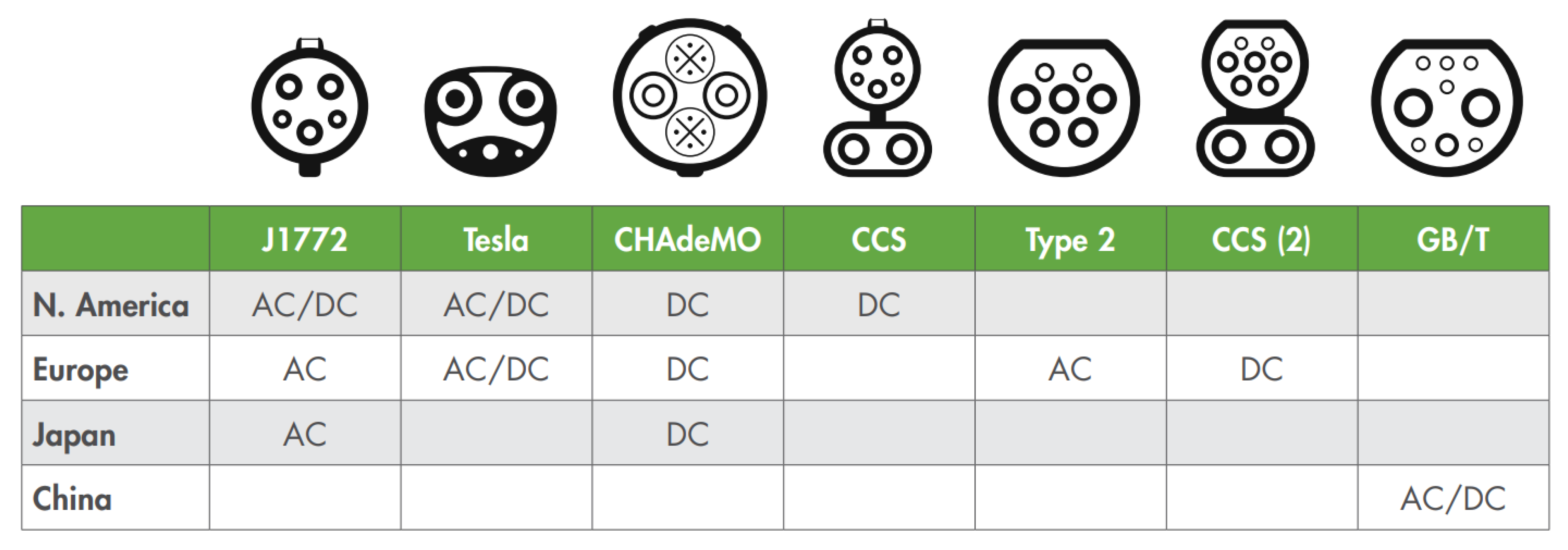
Figure 3.
Schematic summary of power levels for OBC devices and related estimation of charging times.
Figure 3.
Schematic summary of power levels for OBC devices and related estimation of charging times.
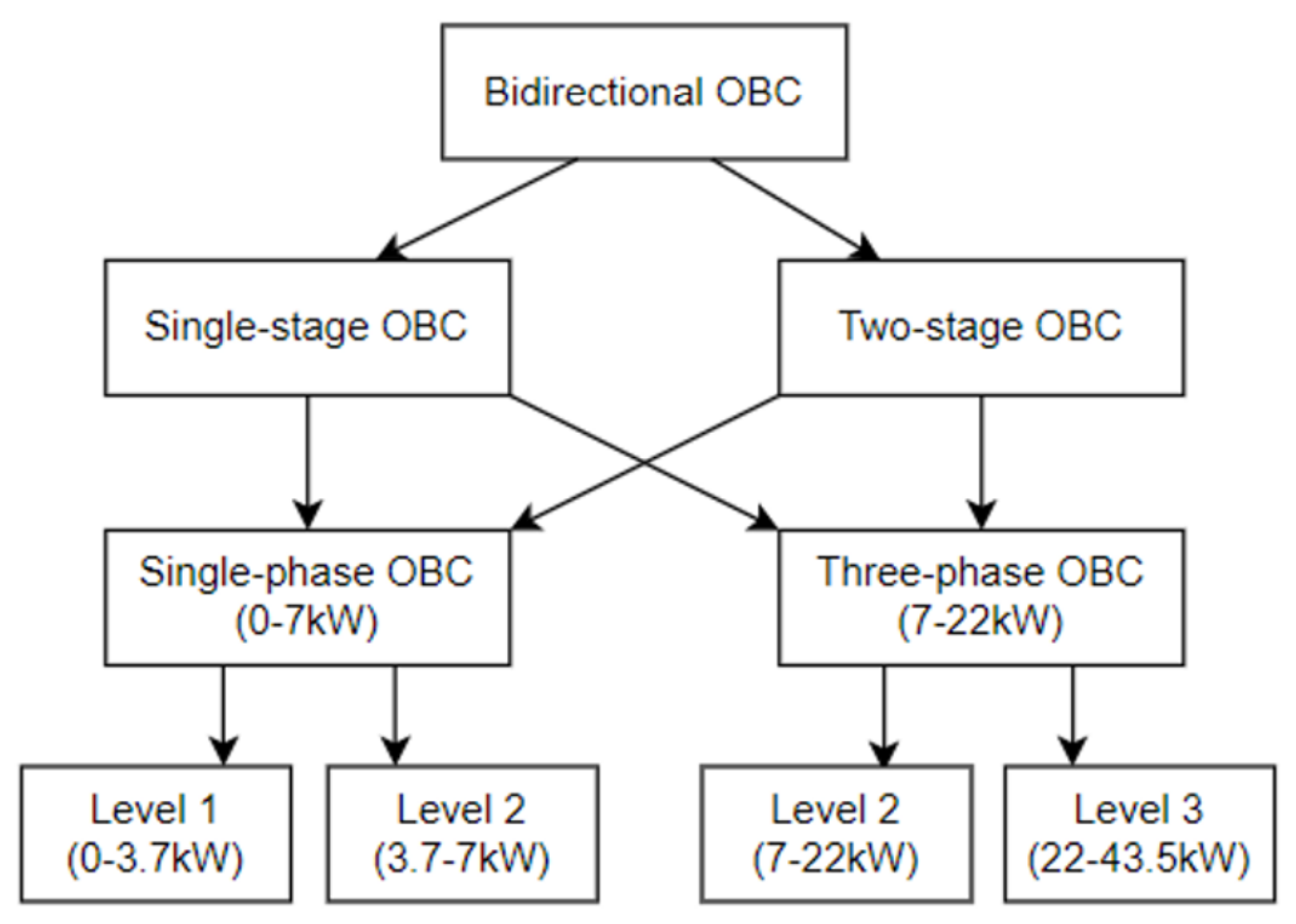
Figure 4.
Typical configurations of an OBC device: (a) single stage with only one device that act as AC/DC; (b) double-stage with a rectifier to reach the DC-link voltage level and a “compact” DC/DC converter connected to the battery; and (c) multi-stage where typical galvanic isolation is integrated.
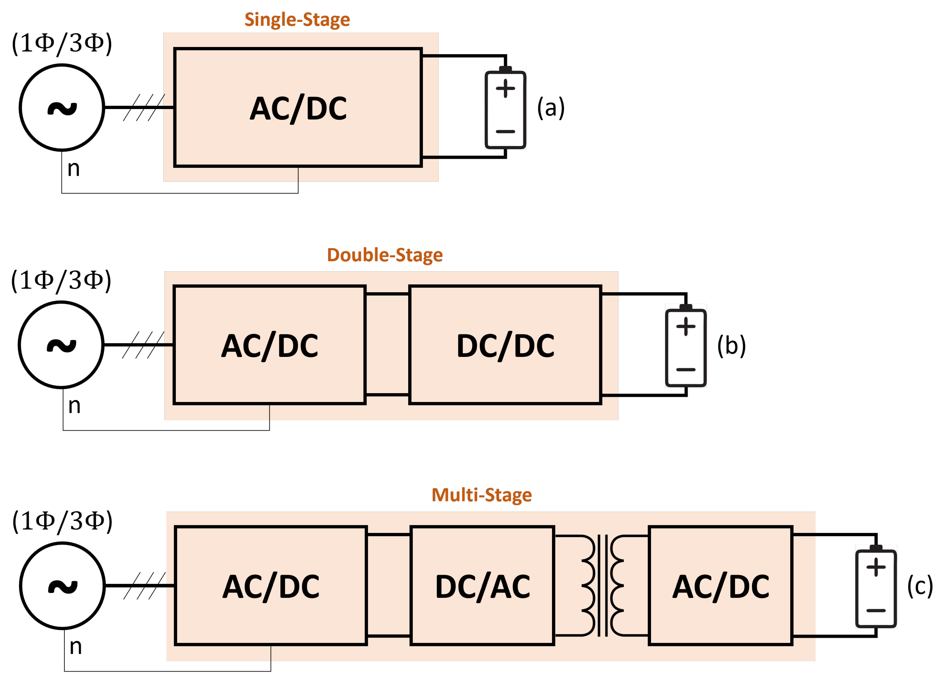
Figure 5.
Basic filter configurations: (a) C-Filter; (b) L-Filter; (c) CL-Filter; (d) LC-Filter; (e) -Filter; and (f) T-Filter.
Figure 5.
Basic filter configurations: (a) C-Filter; (b) L-Filter; (c) CL-Filter; (d) LC-Filter; (e) -Filter; and (f) T-Filter.
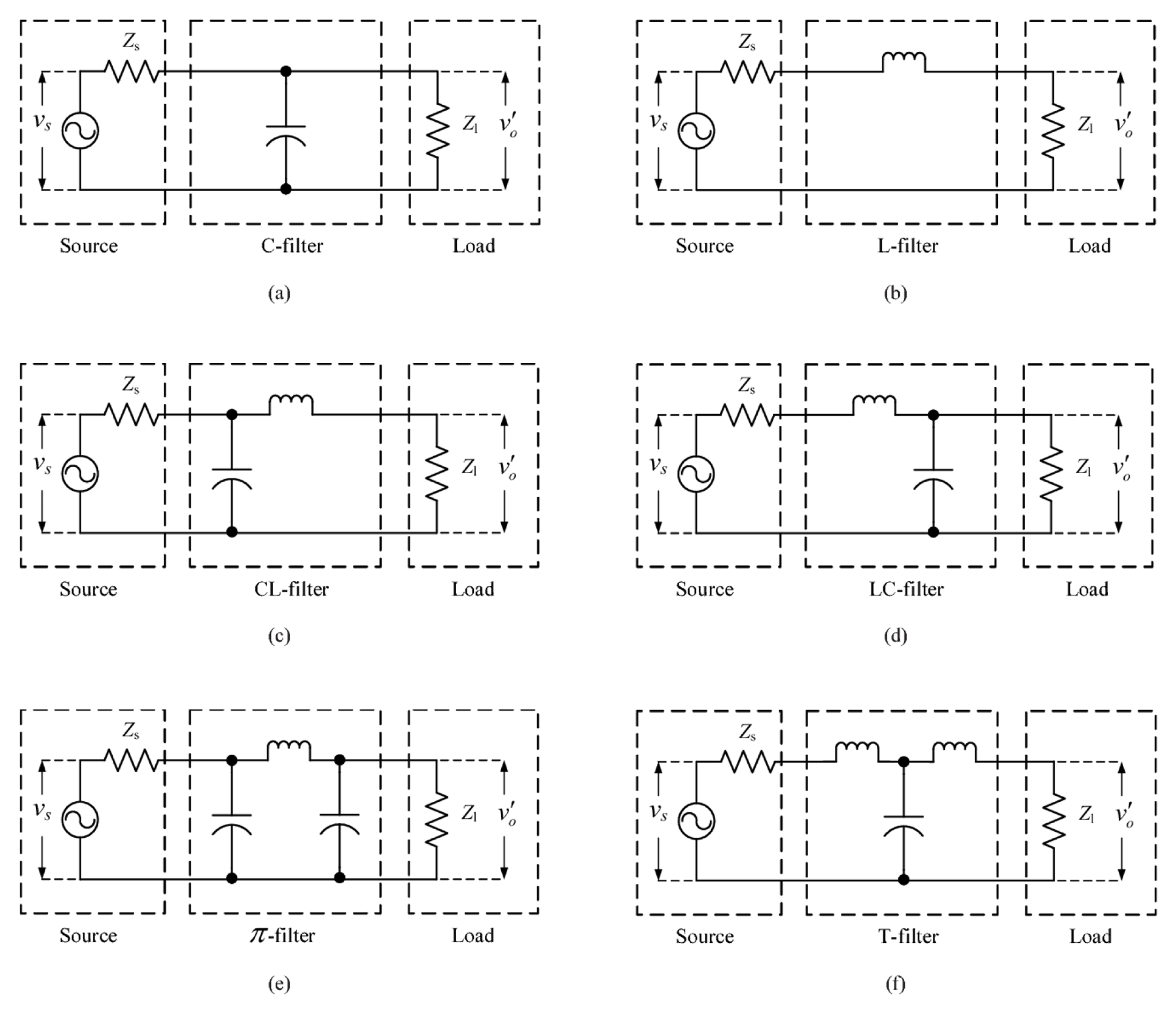
Figure 6.
Typical suitability of various device types based on voltage and switching frequency considerations.
Figure 6.
Typical suitability of various device types based on voltage and switching frequency considerations.
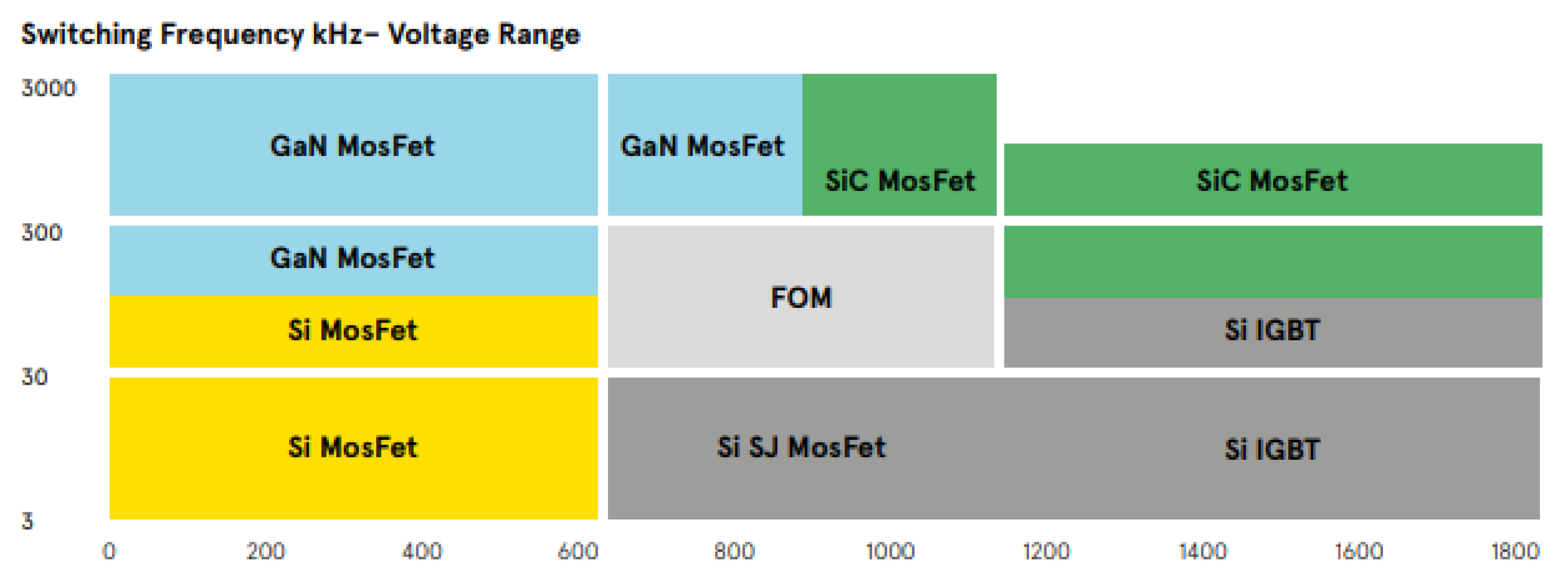
Figure 7.
Comparison of the switching technologies with respect to the coverage of main application features.
Figure 7.
Comparison of the switching technologies with respect to the coverage of main application features.
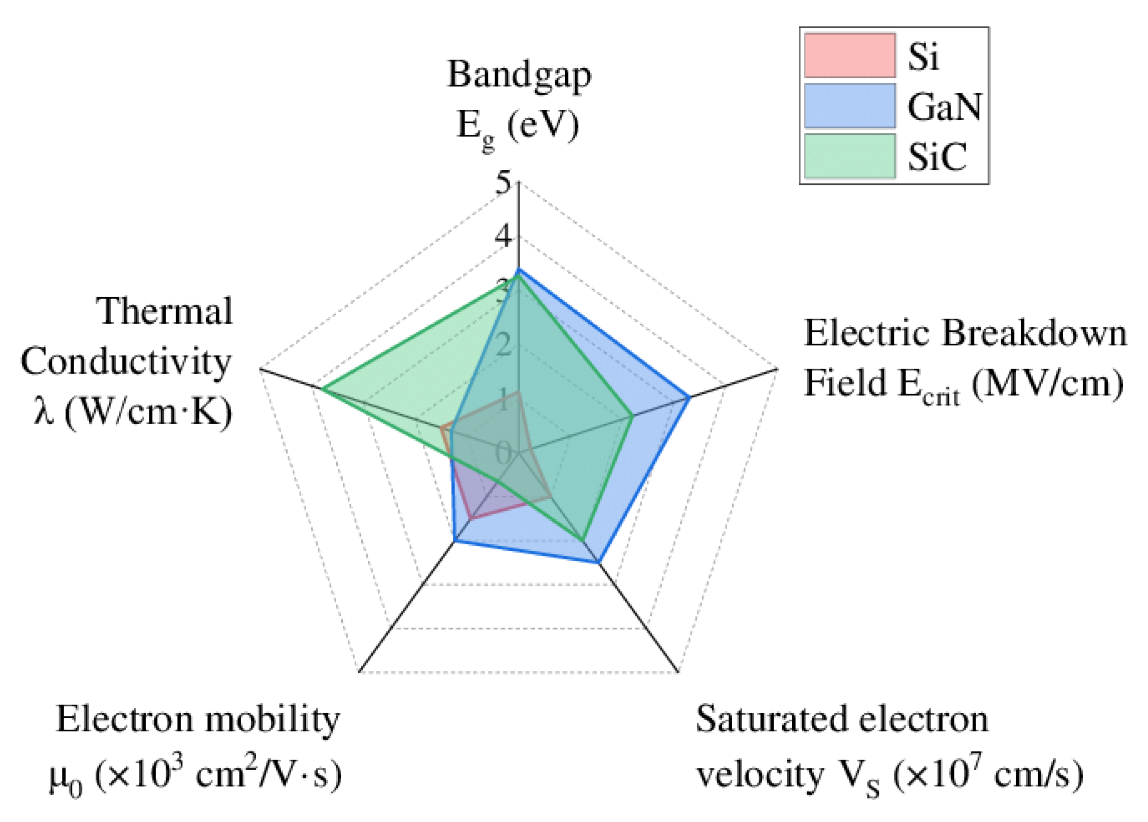
Figure 8.
Interleaved boost PFC schematic.

Figure 9.
Bridgeless Totem-Pole PFC Schematic.

Figure 10.
Interleaved Totem-Pole PFC circuit topology.
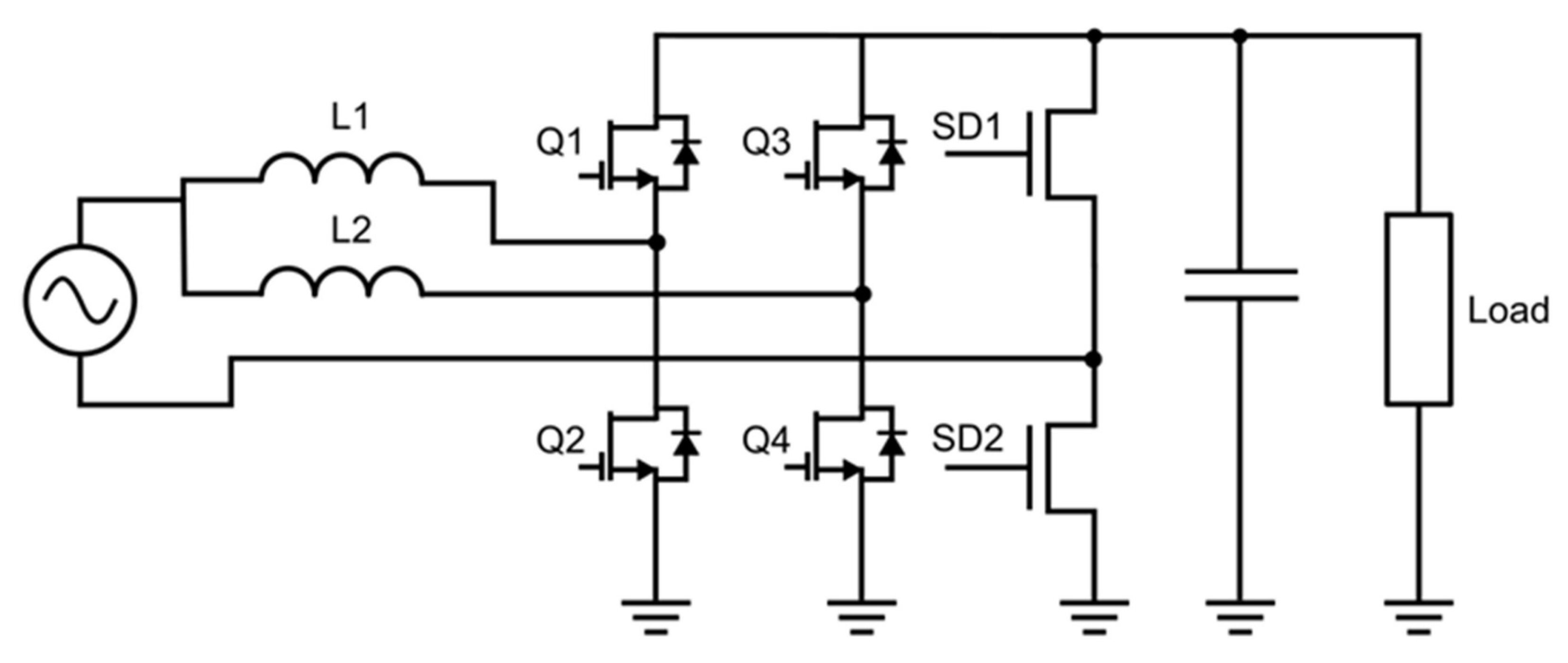
Figure 11.
Typical circuit configuration of a three-phase active rectifier.
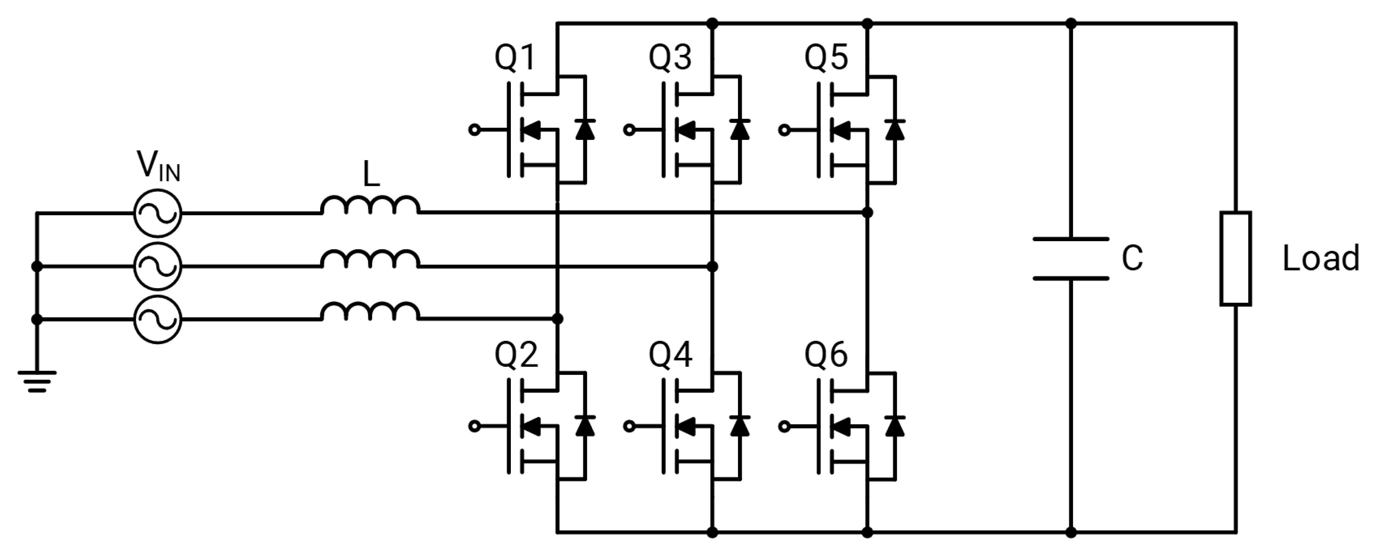
Figure 12.
Typical circuit configuration of a Phase-Shifting Full-Bridge converter.

Figure 13.
Typical Dual Active Bridge Single-phase Circuital configuration.

Figure 14.
Typical Dual Active Bridge three-phase circuits, highlighting galvanic isolation transformer configurations.
Figure 14.
Typical Dual Active Bridge three-phase circuits, highlighting galvanic isolation transformer configurations.
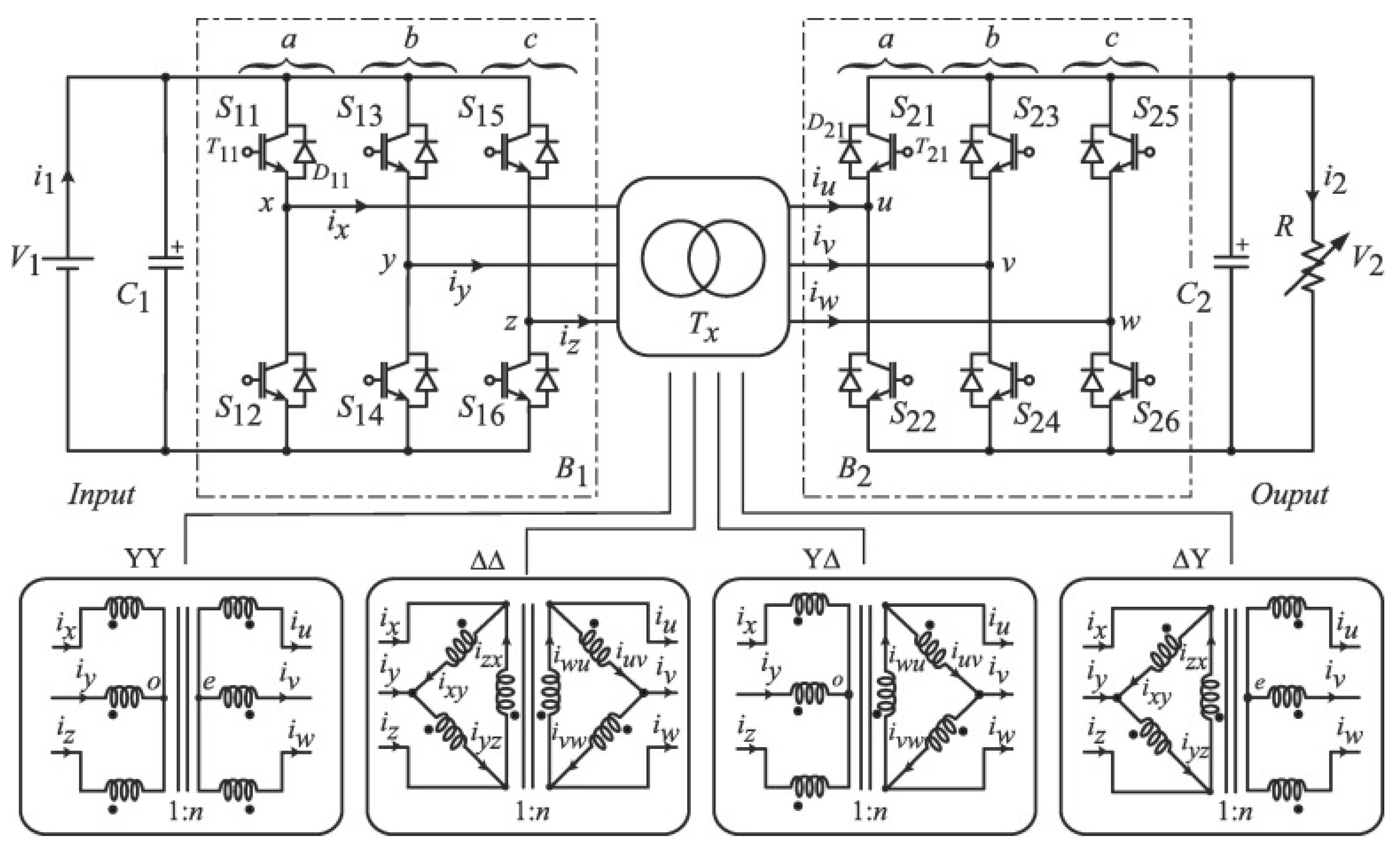
Figure 15.
Typical circuit of LLC converters.
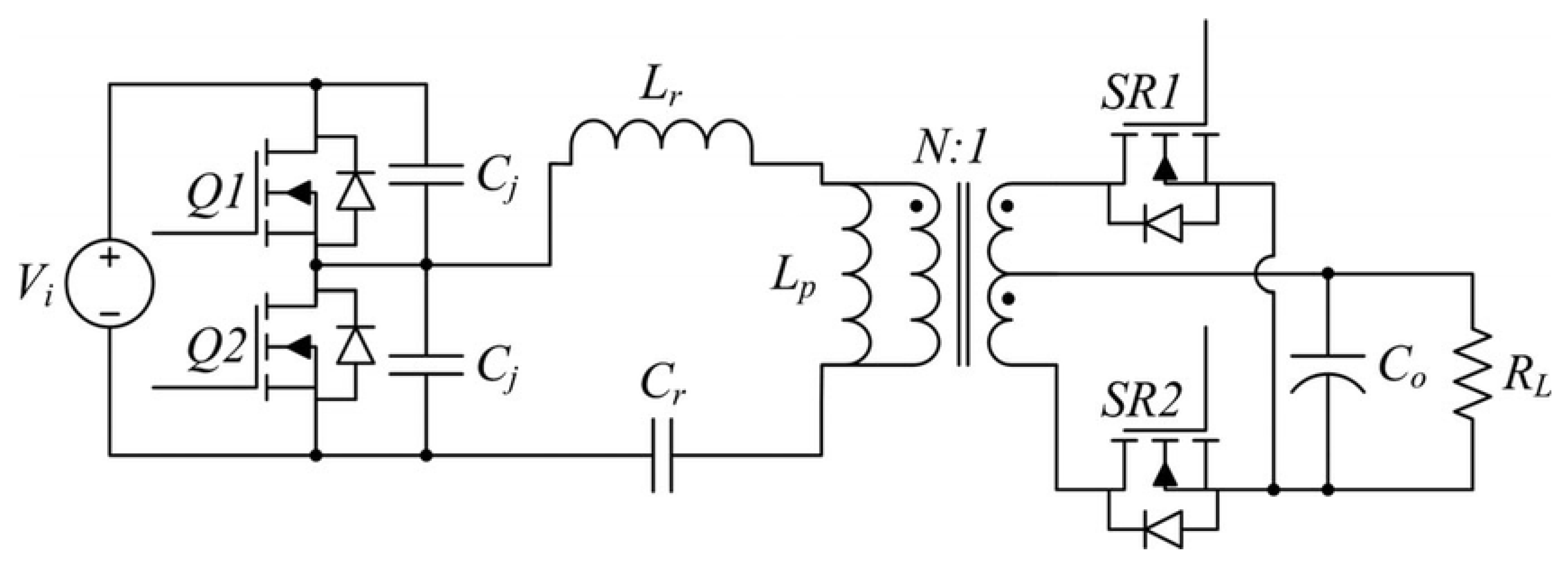
Figure 16.
Typical circuit configuration of a CLLC resonant converter.


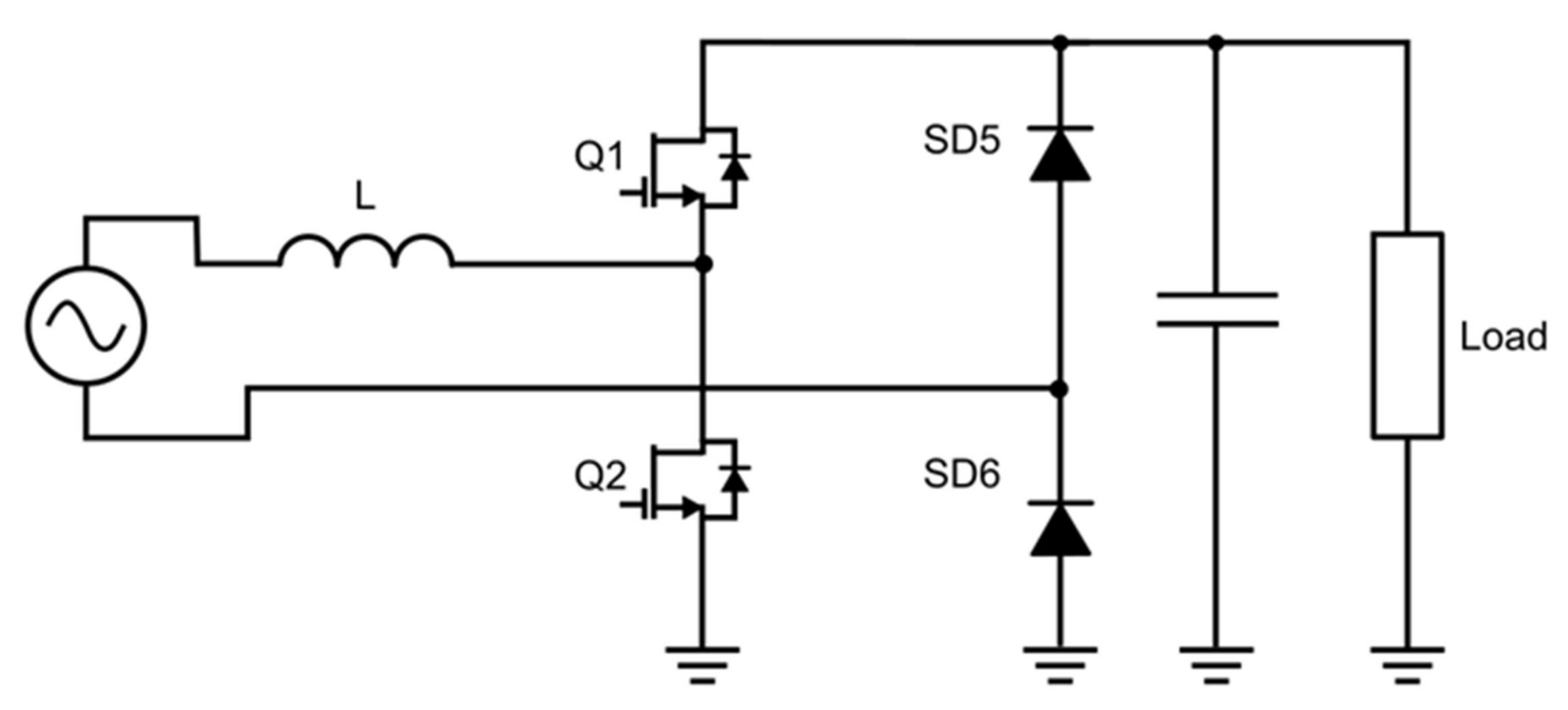
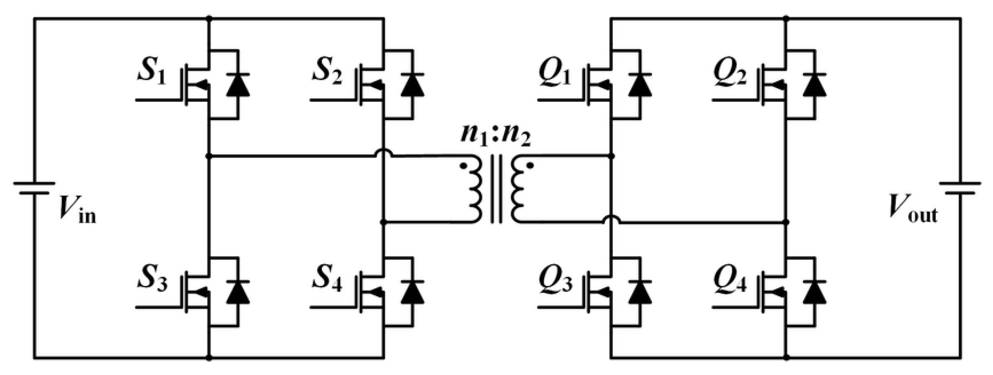
Table 1.
Comparison between off-board and on-board charging systems for electric vehicles.
| Features | Off-Board Charging Systems | On-Board Charging Systems |
|---|---|---|
| Availability of charging stations | Wide presence of public stations in urban areas and along highways. | Accessible wherever there is an electrical outlet, but requires the installation of a dedicated home charging station. |
| Types of charging stations | Public Charging Stations, Rapid Charging Stations, Induction Charging, Home Charging Stations. | Mainly Home Charging Stations. |
| Charging power | High-power DC charging available at many public stations. Rapid Charging Stations offer high charging speeds. | Slower charging compared to high-power public stations. |
| Connector compatibility | Various connector types used but often compatible with a wide range of vehicles. | Standard connection to home outlets or dedicated charging stations with a specific vehicle connector. |
| Charging time | Rapid charging times (usually less than an hour) at high-power public stations. | Longer charging times (varying from several hours to overnight) depending on the charging power. |
| Charging costs | Some public stations may charge usage fees. | No usage fees at home charging stations. |
| Initial installation | Requires no additional installation. | Requires the installation of a dedicated home charging station, incurring associated costs. |
| Advantages | Fast charging, wide availability, ideal for long trips. | Maximum convenience, lower long-term costs, the opportunity to take advantage of cost-effective energy rates, always ready for use. |
| Disadvantages | Potentially higher costs due to usage fees, congestion in some areas. | Slower charging, requires the installation of a charging station, limited to home charging station availability. |
Table 2.
Summary of the main features of the AC/DC commercial solution from most relevant providers.
Table 2.
Summary of the main features of the AC/DC commercial solution from most relevant providers.
| Provider | Topology | PFC | THD | Switching Tech. | ||||
|---|---|---|---|---|---|---|---|---|
| Texas Instruments | TPBPFC [162] | 0.999 | <2% | >0.991 | 4 kW | 200/280 | 400 V | GaN |
| boost PFC [163] | 0.990 | <5% | >0.98 | 3.5 kW | 190/270 | 390 V | IGBT/Si | |
| TPBPFC [164] | 0.990 | - | 0.985 | 7.4 kW | 90/265 | 400 V | GaN | |
| ON-Semi | ITPPFC [165] | - | 5% | >0.90 | 3.3 kW | 90/265 | 400 V | SiC |
| ITPPFC [166] | - | 5% | 0.94 | 6.6 kW | 90/265 | 250/450 V | SiC | |
| TPPFCAR [167] | 0.950 | - | >0.95 | 10 kW | 195/265 | 200/450 V | SiC | |
| Infineon | TPPFCAR [168] | >0.9 | < | >0.92 | 3.3 kW | 175/265 | 400 V | SiC |
| TPBPFC [169] | 0.950 | < | 0.990 | 3.3 kW | 200/250 | 300/450 V | Si/SiC | |
| Wolfspeed | TPBPFC [170] | >0.99 | <2% | 0.986 | 3.6 kW | 180/265 | 420 V | Si |
| TPBPFC [171] | 0.98 | 5% | 0.965 | 6.6 kW | 90/265 | 250/450 V | SiC |
Table 3.
Summary of the main features of the DC/DC commercial solution from most relevant providers.
Table 3.
Summary of the main features of the DC/DC commercial solution from most relevant providers.
| Provider | Topology | THD | Switching Tech. | ||||
|---|---|---|---|---|---|---|---|
| Texas Instruments | DAB [172] | <5% | 0.976 | 10 kW | 700/800 V | 380/500 V | SiC |
| CLLC [173] | <5% | 0.98 | 6.6 kW | 380/600 V | 280/450 V | SiC | |
| CLLC [164] | <5% | 0.98 | 7.4 kW | 400/450 V | 250/450 V | SiC | |
| ON-Semi | LLC [165] | <5% | >0.9 | 3.3 kW | 400 V | 200/450 V | Si/SiC |
| LLC [166] | 5% | 0.94 | 6.6 kW | 400 V | 250/450 V | Si/SiC | |
| LLC [174] | <5% | >0.9 | 10 kW | 700 () V | 200/450 V | SiC | |
| Infineon | LLC [168] | <2% | >0.98 | 3.3 kW | 300/450 V | 60 V (for HV) | Si |
| Wolfspeed | CLLC [171] | - | 0.98 | 6.6 kW | SiC | ||
| CLLC [175] | 2% | 0.985 | 22 kW V2G | 380/900 V | 200/800 V | SiC | |
| 6.6 kW–380/600 V | |||||||
| 6.6 kW V2G | 300/800 V | 365/755 V | SiC |
Disclaimer/Publisher’s Note: The statements, opinions and data contained in all publications are solely those of the individual author(s) and contributor(s) and not of MDPI and/or the editor(s). MDPI and/or the editor(s) disclaim responsibility for any injury to people or property resulting from any ideas, methods, instructions or products referred to in the content. |
© 2023 by the authors. Licensee MDPI, Basel, Switzerland. This article is an open access article distributed under the terms and conditions of the Creative Commons Attribution (CC BY) license (https://creativecommons.org/licenses/by/4.0/).
Share and Cite
MDPI and ACS Style
Dini, P.; Saponara, S.; Colicelli, A. Overview on Battery Charging Systems for Electric Vehicles. Electronics 2023, 12, 4295. https://doi.org/10.3390/electronics12204295
AMA Style
Dini P, Saponara S, Colicelli A. Overview on Battery Charging Systems for Electric Vehicles. Electronics. 2023; 12(20):4295. https://doi.org/10.3390/electronics12204295
Chicago/Turabian StyleDini, Pierpaolo, Sergio Saponara, and Antonio Colicelli. 2023. "Overview on Battery Charging Systems for Electric Vehicles" Electronics 12, no. 20: 4295. https://doi.org/10.3390/electronics12204295
Note that from the first issue of 2016, this journal uses article numbers instead of page numbers. See further details here.