Article

A Binary Fast Image Registration Method Based on Fusion Information

1
College of Electro-Mechanical Engineering, Changchun University of Science and Technology, Changchun 130022, China
2
Changchun Institute of Optics, Fine Mechanics and Physics, Chinese Academy of Sciences, Changchun 130033, China
*
Author to whom correspondence should be addressed.
Electronics 2023, 12(21), 4475; https://doi.org/10.3390/electronics12214475
Submission received: 30 September 2023 / Revised: 22 October 2023 / Accepted: 25 October 2023 / Published: 31 October 2023

Abstract

:
In the field of airborne aerial imaging, image stitching is often used to expand the field of view. Registration is the foundation of aerial image stitching and directly affects its success and quality. This article develops a fast binary image registration method based on the characteristics of airborne aerial imaging. This method first integrates aircraft parameters and calculates the ground range of the image for coarse registration. Then, based on the characteristics of FAST (Features from Accelerated Segment Test), a new sampling method, named Weighted Angular Diffusion Radial Sampling (WADRS), and matching method are designed. The method proposed in this article can achieve fast registration while ensuring registration accuracy, with a running speed that is approximately four times faster than SURF (Speed Up Robust Features). Additionally, there is no need to manually select any control points before registration. The results indicate that the proposed method can effectively complete remote sensing image registration from different perspectives.

1. Introduction

Aerial remote sensing images have the outstanding advantages of being quick to obtain and flexible to use, and they have wide applications in environmental monitoring, situation awareness, geographic information system construction, and other fields [1,2,3]. However, due to the size limitations of aerial camera sensors, there is often a trade-off between the field-of-view range and the ground resolution. The commonly used technical approach is to continuously acquire images, ensuring a certain overlap rate of the area of interest, and then synthesize them into a large-scale panoramic image using image stitching technology. Here, registration plays a decisive role in aerial image stitching, and directly affects its success and quality [4]. Due to the poor stability of UAVs and their vulnerability to interference from the external environment and other factors, airborne aerial images often have problems such as changes in brightness, geometric distortion, atmospheric turbulence, and motion blur; therefore, it is necessary to design a stable and effective image registration method that has good robustness and invariance against lighting, distortion, blur, etc. [5,6,7]. At the same time, aerial image stitching requires a lot of time, so the speed and efficiency of the registration method should also be considered [7]. Conventional image stitching methods require a large amount of computation. The constraints on the weight and volume of airborne equipment are strong, and the hardware computing power is limited. At the same time, there are requirements for real-time performance, so it is necessary to minimize the computational load as much as possible. In addition, existing software, such as OpenCV, requires accessing various libraries, and there are also many issues when porting to embedded systems. Although rapid image registration technology has undergone decades of development, there are still few targeted studies in the field of airborne aviation imaging, so it is of great significance to develop a high-precision fast registration method for these remote sensing images. In this paper, a binary fast registration method based on fused information is proposed to realize real-time registration of aerial remote sensing images.
Image registration methods can be divided into region-based methods, feature-based methods, and hybrid-model-based methods. Feature-based methods are the most widely used due to their high robustness. Among them, the SURF algorithm is an improved version of the SIFT (Scale Invariant Features Transform) algorithm; it has a better registration effect and improves the detection speed of feature points [8,9]. However, when processing large-scale remote sensing images, its calculation time can reach the order of minutes, so reducing the calculation requirements is a very urgent task in aerial image processing [10,11].
Harris’ algorithm has received recognition because of its high detection and repetition rates, but it is more sensitive to changes in the angle of the image, and some improved algorithms have since appeared, such as the Shi–Tomasi corner detection algorithm [12,13]. Due to the requirement for fast processing in these algorithms, Rosten et al. proposed the FAST feature point detection algorithm, which is very quick because it does not involve complex operations such as scale and gradient. [14]. However, it is not directional or scale-invariant.
At the same time, in terms of the matching strategy, binary-based registration methods are fast and have easy hardware implementation. In recent years, researchers have proposed many binary image descriptor-based methods to solve the problem of remote sensing image registration. Michael Calonder et al. proposed BRIEF: Binary Robust Independent Elementary Features [15]. The BRIEF descriptor uses a binary string as the descriptor vector, but because its sampling mode is solidified and has no principal direction, large angular rotation has a great impact on matching. Ethan Rublee et al. proposed the ORB (Oriented FAST and Rotated BRIEF) algorithm [16]. They added directionality to FAST feature points, gave the feature points rotational invariance, and proposed a pyramid construction method to solve scale invariance. The BRISK algorithm (Binary Robust Invariant Scalable Keypoints) proposes a circular sampling mode that calculates the contrast of brightness to form a binary descriptor string. It has good rotational invariance, scale invariance, and better robustness. Its cassette descriptors are typically calculated an order of magnitude faster than SURF [17]. However, BRISK reduces the number of sample points at the expense of matching quality, limiting its application scenarios. Liang H et al. treated all feature points as a whole and generated a new binary descriptor with high accuracy and robustness for multi-sensor remote sensing images [18]. Fuzhen et al. proposed an improved directional FAST and rotational BRIEF random sampling consistency (ORB-RANSAC) algorithm, which significantly increases the number of detected feature points and distributes more uniformly than the traditional ORB algorithm, but it has poor applicability to remote sensing images with geometric deformation [19].
Image processing based on deep learning has been widely applied in various fields, including remote sensing image registration [20,21,22]. These methods use deep learning to construct various network models to learn feature representations from different images, thus achieving automatic image registration [21,22]. However, the effectiveness of image registration is related to specific application scenarios. The deep learning-based method performs well in terms of accuracy in certain specific applications. However, due to the significant changes in types of landscape in the flight path of aircraft, such as urban areas, villages, fields, and deserts, deep learning requires a large number of different types of sample libraries, which is difficult in airborne aviation applications, resulting in poor robustness of deep learning. Additionally, due to strong constraints on the weight and volume of airborne equipment, hardware computing power is limited, and processing efficiency is not ideal. Therefore, the application of deep learning in airborne image registration is relatively limited.
The point-based feature-based approach can be divided into three steps: feature extraction, feature description, and feature matching. In practical applications, after feature matching is completed, it is necessary to calculate the transformation relationship between the two images according to the successfully matched feature points and map the image to be registered to the coordinate system of the reference image. In the classical method, in order to make the transformation model more accurate and the success rate higher, it is often necessary to extract as many feature points as possible. For example, solving the model parameters for affine transformations requires at least three pairs of points with the same name in two images. If the feature points extracted in the image to be registered need to be described and matched one by one with the feature points in the reference image in a certain order, then the calculation is heavy.
Various other classical methods often do not work well in practical applications due to a lack of relevance.
First of all, their operating speeds do not meet real-time processing requirements. Algorithms with high registration success rates tend to be computationally intensive, while methods that run quickly are usually prone to registration failure because they are oversimplified.
Secondly, as airborne images are often captured with the line of sight tilted to the ground, there is a perspective projection effect on the ground coverage area of the image, presenting an irregular quadrilateral shape. The specific shape is affected by the direction of the optical axis, as shown in Figure 1.
As a result, images taken at different times often exhibit significant geometric distortions. In addition, due to the different imaging times of image sequences, the brightness, gradient, and other characteristics of the same object and its background in different images exhibit differences under the influence of atmospheric disturbances or aircraft vibrations. That is why images with a large rotation transformation (RT) are difficult to register. The global geometric deformation caused by great RT and significant differences in local appearance caused by different imaging mechanisms must be dealt with [22]. Many directly neighborhood-based algorithms may result in significant differences in descriptors due to inconsistent neighborhood features, leading to mismatches. For example, in the two images taken as depicted in Figure 1, due to the significant difference in inclination angles and the significant changes in neighborhood features caused by perspective effects, a pair of SURF descriptors with the same name extracted from the two images have significant differences and cannot be matched, as shown in Figure 2.
Therefore, in response to the above issues, this article uses binary description as the basis and combines information such as drone flight parameters to complete remote sensing image registration, which not only ensures fast registration but also has high accuracy. By using a coordinate transformation method for image mapping, the computational burden of registration can be effectively reduced. This article then improves the FAST extraction process and combines it with a Gaussian kernel angle diffusion template to generate a sampling template, constructing a new binary descriptor. This method can effectively reduce the environmental impact under airborne conditions, improve the registration success rate, and ensure computational efficiency. Additionally, there is no need to manually select any control points before registration. The results of this study indicate that the proposed method can effectively complete remote sensing image registration from different perspectives.

2. Theory and Methods

The challenges typically faced by image registration include grayscale differences, rotation, scaling, and translation. Another issue that must be addressed in image registration for airborne image stitching applications is the perspective effect caused by changes in perspective, which manifests as geometric distortions of objects in the image and inconsistent distortion parameters as a result of different perspectives. At the same time, it is necessary to consider the image processing speed. In order to ensure the speed and improve the success rate of image registration, this article specifically designs a fast registration method based on coarse-to-fine fused data. This method combines the position, heading, attitude, imaging parameters, and angle information of the imaging system of the carrier to complete coarse registration, reducing the computational complexity required for image registration. Then, this method takes the previous image as the reference image and, within the set error tolerance, uses a binary matching method for the overlapping areas to improve operational efficiency, perform accurate registration calculations, and optimize the parameters of the image transformation model. This method can achieve rapid image registration in airborne embedded systems, providing a reference for subsequent stitching processing. The approximate framework is shown in Figure 3.

2.1. Preprocessing and Rough Registration Based on Geographic Information

In the field of airborne image processing, timeliness is one of researchers’ key concerns. When performing image stitching, due to significant fluctuations in the flight speed, ground coverage, and scene illumination of Unmanned Aerial Vehicles (UAVs) and other aircraft, the overlap range of sequence images also changes during stitching. For airborne image stitching, only the overlapping areas between two images are necessary for the registration calculation. It is a waste of time to perform image feature extraction and matching on non-overlapping areas. To solve the above problems, the method of geographic location mapping can be used to calculate the geographic positions of the image center and the four vertices of the image. This calculation process typically requires a low level of computation, and through this relatively small amount of geographic location mapping, three obvious advantages can be obtained. For one, it can determine the overlapping area between two images, avoid extracting feature points in non-overlapping areas, and save a large amount of computation power. Secondly, it can ensure that the image to be registered has unified geometric parameters, ensuring that the actual ground scene corresponding to the neighborhood of the feature points is consistent. In addition, the true north direction of the image can also be determined, thereby unifying the direction of feature point descriptors in advance. In the subsequent feature point-matching process, there is no need to set the main direction.
During flight, the aerial imaging system is mounted on the base of an aircraft, such as a UAV, and the image is the projection of the target area on the image sensor, located in the camera coordinate system. The actual position that usually needs to be calculated is the coordinates of the ground, such as the WGS-84 coordinate system used by GPS, which includes three coordinate values: longitude L, latitude M, and altitude H.
In the process of converting the target from the camera coordinate system (system C) to the geodetic coordinate system (system G), the use of an intermediate coordinate system is required to assist in completing coordinate conversion, which is also a prerequisite for the localization calculation. Usually, the number of intermediate process coordinate systems needs to comprehensively consider the localization requirements, the main equipment integrated with the carrier and its installation location, the structure and installation method of the aviation optoelectronic platform, etc. This article establishes four intermediate process coordinate systems, namely platform coordinate system P, UAV body coordinate system B, UAV geographic coordinate system V, and an Earth-centered Earth-fixed coordinate system (ECEF; system E).
The core process of the target localization method adopted by this paper is shown in Figure 4.
Since the purpose of image registration is not to obtain the longitude and latitude of the target area, but to map the image to a reference coordinate system that does not move with the carrier, it only needs to be converted to the ECFF coordinate system. This coordinate system is already based on the geocentric coordinate system, which can meet the needs of image mapping and avoid complex iterative operations during the conversion to the geodetic coordinate system. Therefore, the four vertices and center points of the image can be transformed into the ECFF coordinate system through homogeneous coordinate transformation.
The homogeneous coordinates of a target in the camera coordinate system are
[ x c   y c   z c   1 ] T = [ u   v   f   1 ] T
where u and v are the target’s coordinates in the image (in pixels), and f is the current focal length of the camera. Usually, when the UAV detects a target, the photoelectric platform will lock the detected target in the center of the field of view (FOV) with multiple pixels, and then the target is in the center of the image. When an error inside the camera coordinate system is ignored, the homogeneous coordinates of the target can be expressed as [ 0   0   f   1 ] T . The camera carrier is a photoelectric platform, which outputs information on angles a and e between the line of sight (LOS) and the zero positions of two platform angles and measures the target distance R through a laser range finder. Since the platform uses a polar coordinate system, the below coordinate transformation is needed:
[ x p   y p   z p   1 ] T   =   R × Q p c [ 0   0   f   1 ] T
where Q p c is the conversion matrix from the camera coordinate system C to the platform coordinate system P.
Q p c = [ cos a 0 sin a 0 0 1 0 0 sin a 0 cos a 0 0 0 0 1 ] [ 1 0 0 0 0 cos e sin e 0 0 sin e cos e 0 0 0 0 1 ]
The other conversion processes are similar. Through the above process, the geographic positions of the image center and the four vertices of the image can be mapped to the ECEF coordinate system based on their geographic positions using only us-level operations, as shown in Figure 5. In the subsequent process, the previous frame image can be used as a reference, and the next frame image to be registered can also be mapped to the coordinate system.
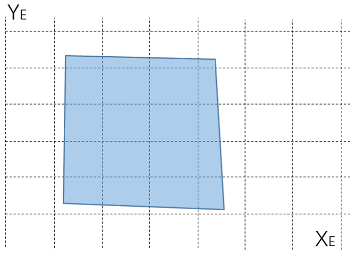
Under a unified coordinate system, the scale between the two images is also unified, which means that the problem of scaling between the two images can be roughly solved and the overlapping area can be determined by the intersecting area, as shown in Figure 6.
However, due to the influence of transmission errors, measurement errors, and other errors, the results usually have m-level errors. The corresponding errors on the image are usually more than 5 pixels, but generally do not exceed 200, as shown in Figure 7. From the figure, it can be seen that there is obvious misalignment in the images after simple overlap. The error needs to be corrected through pixel-level image registration methods.
After coarse registration of images is performed through geographic location mapping, a pixel-level image registration method needs to be adopted to optimize the scale and shift parameters for the subsequent stitching process. At this point, feature point extraction, feature point description, and matching require improvements to meet real-time requirements due to their high computational complexity.

2.2. FAST Feature Point Detection Method

At present, the fastest feature point detection method is FAST. The basic idea of this method is to construct a circular ring with any pixel in the image as the center. By comparing the grayscale value of the center point with the grayscale value of 16 pixels on the ring, the feature point can be determined. When the grayscale value of the center point is always greater than or less than the grayscale value of 9 consecutive pixels on the ring, it is determined that the center point is a feature point. Then, through non-maximum suppression, the final set of feature points extracted by the FAST detection method can be obtained.
By default, this method compares and detects 16 surrounding pixels, and there are also detection methods for 12 or 9 neighboring pixels, as shown in Figure 8. It can be seen that the sampling radius decreases sequentially, corresponding to 3 pixels, 2 pixels, and 1 pixel, respectively.
Although the principle of the FAST feature point detection method is relatively simple, in-depth analysis can reveal that the current description methods for FAST feature points are often not thorough enough in analyzing the relationship between pixels and neighborhoods, and the feature points detected by this method cannot be simply identified as corner points. As shown in Figure 9, when there are 16 consecutive points that meet the conditions, they may be blob points; when there are 14 consecutive points that meet the conditions, they may be the endpoints of the line feature; and when there are 11 consecutive points that meet the conditions, they correspond to a more ideal right-angle position. Based on experience, this is often associated with relatively stable and reliable features, such as smaller targets, linear objects, building edges, etc. It is obvious that neighborhood points that continuously meet the conditions represent different types of targets, and in common research work, violent matching is often used without distinguishing these surrogate feature points, which wastes a lot of computational resources.

2.3. Improvements in FAST Feature Point Detection Method

The key steps of image registration include feature detection, the generation of feature descriptors, and key point matching. After feature point extraction is completed, it is necessary to construct a descriptor for the feature point so that it has specificity relative to all other feature points in the image; on the other hand, this description method also needs to ensure that the corresponding point of the same name has similarity to another image in order to ensure that the pair of points can form a corresponding relationship between the two images.
For binary feature point descriptors, there are only two forms: 0 and 1. Therefore, the selected sampling method has become one of the key factors determining the effectiveness of descriptors. For example, the BRIEF algorithm and ORB algorithm heavily rely on sampling templates. The BRISK algorithm adopts a relatively fixed sampling mode, but requires secondary sampling after determining the main direction, resulting in a slightly larger computational load. Meanwhile, these description methods do not use information from the extraction process, resulting in a waste of computing resources.
Therefore, even though the current registration method to extract feature points based on FAST is relatively fast, there is still room for improvement. After studying the relationship between FAST feature points and neighborhoods, this article has made specific improvements.
Firstly, when describing and matching feature points, FAST feature points are clearly divided into “bright feature points” and “dark feature points” to represent the relationship between feature points and their neighbors, and the extraction process is recorded. The basis for this improvement is that for homologous aerial images, feature points will not undergo light–dark reversal within a small time interval. Although there may be changes in brightness, the relative relationship will not undergo fundamental changes. Based on the above settings, this article designs a new feature description method. Firstly, a 16-bit binary description vector was added to record the grayscale relationship between the point and its neighborhood, and the accumulation and differentiation of these 16 bits were used to distinguish between the set of bright feature points {B} and the set of dark feature points {D}. This is because, when comparing brightness, if there are 9 consecutive points with grayscale values greater than the threshold of P points, it is proven that P points are dark points. The number of “1” in these 16-bit description vectors should be ≥9, that is, the sum of each bit should be ≥9. Conversely, if the number of 0 values is greater than 9, the sum of each bit should be less than 7, and the extracted feature points are bright points. Based on this, a total of four feature point sets, {B1}, {B2}, {D1}, and {D2}, can be obtained from the two images. When performing feature point matching, the corresponding feature points can be taken for calculation.
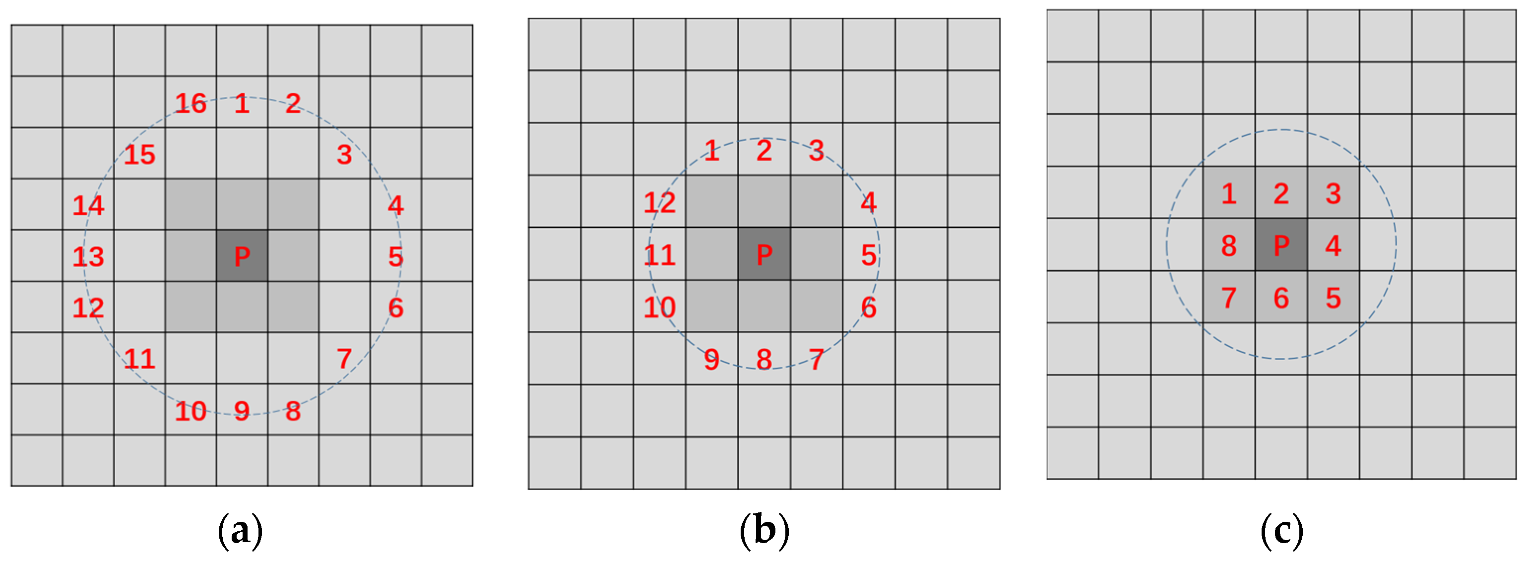
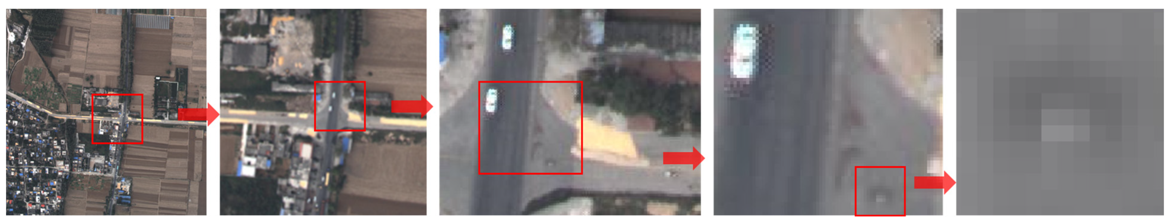
Secondly, based on the number of consecutive neighborhood points that meet the conditions, blob points, lines, and corner points can be distinguished. For FAST with a radius of 3 pixels, if the difference between the 16 detection points and the center point during the extraction process meets the threshold, i.e., all 0 or all 1, it represents that the center point is the extreme value of the region. However, due to advancements in modern sensor technology, the number of pixels in a single image is often over one million, and it is rare for a small object to occupy only one pixel in airborne images. This is reflected in the image array, where at least one point in the surrounding 8 pixels has a small difference in its grayscale, as shown in Figure 10. It can be seen that an object with a very small actual size occupies two brighter pixels in the image, and four adjacent pixels are also bright. Therefore, for suspected blob points, another FAST detection is performed with a radius of 1. When at least 1 of the surrounding 8 points does not meet the threshold for its grayscale difference, the possibility of the point being noisy can be ruled out, and it can be recognized as a blob point; otherwise, it can be determined to be noisy and removed. When there are 13–15 consecutive points that meet the conditions among the 16 points, it can be considered that the endpoints of some approximately linear objects have been detected. When 9–12 out of 16 points meet the conditions, they can be temporarily designated as corner points. It is worth noting that the preliminarily determined feature points require non-maximum suppression to reduce feature point clustering.
However, after constructing a 16-bit descriptor for feature points based on the extraction process, it still cannot meet the requirement of specificity in the matching process; that is, it cannot guarantee the uniqueness of the description vector for thousands of feature points, so it is necessary to increase the description dimension.
Due to the use of a circular neighborhood for sampling testing during feature point extraction, this method introduces a polar coordinate system description method. The method generates a sampling template based on an angle diffusion model and a circular neighborhood, which divides the circumference of a feature point into several regions according to the angle. Weighted variable region sampling is then performed on the sector neighborhood of the feature point to generate a feature point descriptor. This is referred to as the Weighted Angular Diffusion Radial Sampling (WADRS) method in this article. This model can to some extent solve the feature changes in sequence images caused by frequent changes in external conditions.
The specific methods are as follows:
Firstly, based on the size of the sampling template, the range normalization is set to ±0.5 for the X and Y matrices; for example, when the template is n × n,
( x , y ) 1 n [ ( n 1 ) / 2 , ( n 1 ) / 2 ]
where n is set to 21.
This matrix corresponds to an angle matrix θ , where the elements of the matrix θ are
θ = arctan ( y / x )
When the sampling angle is α , the difference between sine and cosine is calculated separately, i.e.,
{ d s = sin θ cos α cos θ sin α d c = cos θ cos α + sin θ sin α
and at this point, the angular distance is
d θ = | arctan ( d s / d c ) |
Then, the angle diffusion model of the Gaussian kernel can be obtained:
f ( θ ) = exp ( ( d θ ) 2 2 σ θ 2 )
Here, σ θ = π / ( k σ d θ ) .
The circumference is evenly divided into 2 × K sampling intervals, and σ d θ is the ratio of the angular interval between filter orientations and the standard deviation of the angular Gaussian function used to construct filters in the frequency plane.
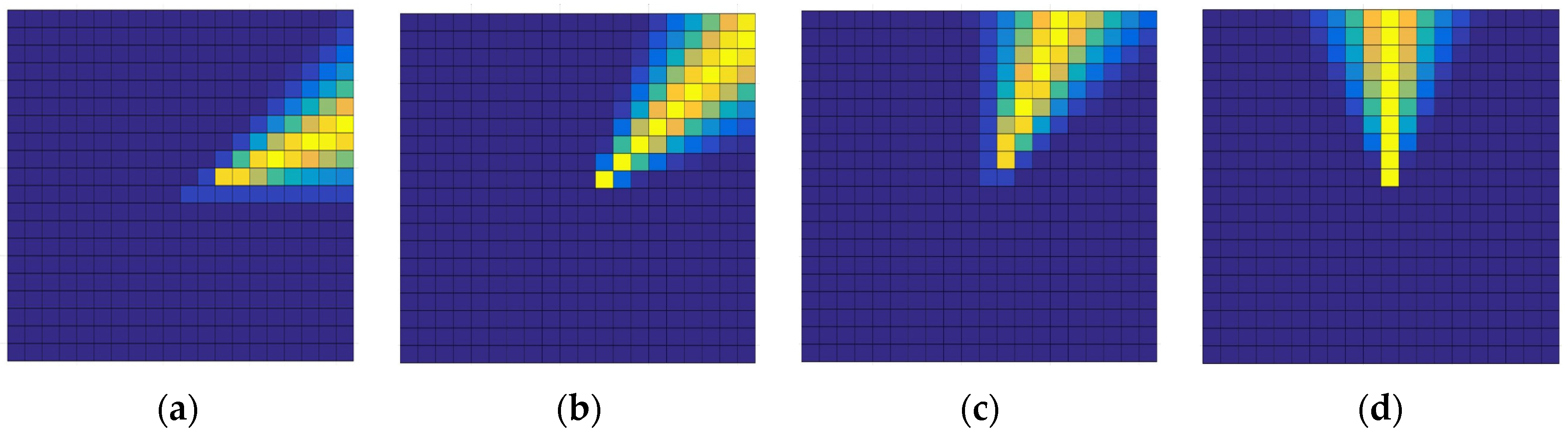
The sampling template obtained from this is shown in Figure 11a, with a size of 21 × 21 and a sampling angle of 22.5°. Different colors represent different weights. This means that the circumference is divided into 16 angle intervals, corresponding to the 16 sampling directions during FAST feature point extraction. The weight values of each position within the sampling angle are shown in Figure 11b.
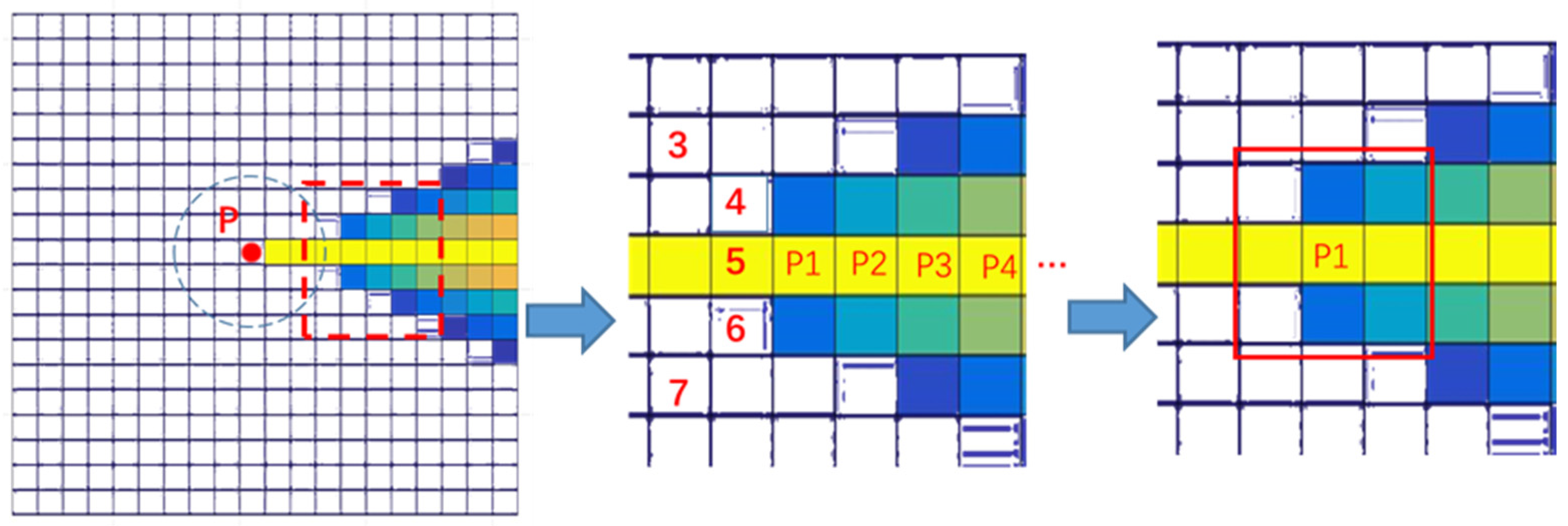
Based on the premise that the target occupies multiple pixels as described earlier, the 7 × 7 neighborhood with a radius of 3 centered on the feature point is no longer sampled, but is instead sampled radially outward. The center of the circle (feature point, red point P in Figure 12) is divided outward into m small sampling intervals based on different radii, and the values of the sampling template are used as weights for weighted and normalized brightness testing, as shown in Figure 12.
The value of the small sampling interval centered on P1 is Ip1
I p 1 = I R P 1 , w R P 1 I i w i w R P 1 w i
Here, w i is the value of the sampling template in the 3 × 3 neighborhood where point P1 is located. That is, when point P1 is taken as the center of the small sampling interval, the brightness values of 9 pixels in its 3 × 3 area are multiplied and summed with the sampling template, and then normalized. The obtained IP1 can be compared with the brightness Ip of feature point P, thus obtaining a binary comparison result. By extrapolating along the radial direction in sequence, an l-bit binary descriptor can be obtained. It should be noted that when the sampling angle changes, interpolation methods need to be used to resolve the situation where the sampling interval is not at the center of the pixel. According to different needs, simple rounding can be used to form a sampling template to accelerate the calculation speed, as shown in Figure 13. In addition, due to the independence of each sampling interval, 16 angle intervals can be simultaneously sampled through parallel computing to improve the speed of descriptor construction.
Based on this, the feature point description method designed in this article is as follows: firstly, a 16-bit circular neighborhood feature S is added, and 7 brightness test results within 16 angle intervals are recorded in binary form. Therefore, the descriptor for each feature point is a 128-bit binary vector.
As the images are mapped using geographic information, the directions in the two images are largely consistent. Due to the size of the sampling template, the angular error in the geographic information is not sufficient to cause sampling errors.

2.4. Matching of Feature Point Descriptors

Due to the small error in the calculation results of geographic information, the search range can be defined based on the position of feature points in the ECEF coordinate system before descriptor matching is performed. Usually, during the matching stage of feature point binary descriptors, Hamming distance is used to evaluate the similarity between descriptors.
The Hamming distance represents the number of different bits corresponding to two code strings of the same length. XOR is performed on two strings and the number of results is counted as 1. The number of 1 represents the Hamming distance between two strings. The calculation formula is shown in Equation (10).
D H ( x , y ) = i = 0 k 1 j = 0   j i k 1 a i j
Based on the modification of FAST in this article, when matching feature points in two images, there is no need for brute-force matching, but a tree search method is used instead to improve efficiency. Firstly, based on whether the feature points come from {D} or {B}, they are assigned to the corresponding subset and then further divided into smaller subsets based on the absolute value of the ring neighborhood feature S. In theory, when calculating the Hamming distances of the circular neighborhood features S1 and S2 from two feature points in two images, the two feature points with the smallest distance are most likely to be points with the same name. Therefore, sorting can be based on the Hamming distance between S vectors first. Usually, due to perspective projection in aerial images, the change in neighborhood features does not exceed one quadrant, so the Hamming distance between S vectors usually does not exceed 4. Due to using only a 16-bit S vector for the initial sorting, the filtering speed is fast and the efficiency is high. When the Hamming distance of the S vector meets the condition, the Hamming distance between the remaining 16 × 7 bits is calculated to complete the matching.
The relative position relationship of feature points can be determined based on geographic information, so it can eliminate mismatched points that are significantly out of the tolerance range more effectively than the Random Sample Consensus (RANSAC) method, thereby ensuring the accuracy of registration.
After feature point matching is completed, an accurate image transformation model can be calculated to complete image registration, laying a solid foundation for subsequent processing processes such as stitching and fusion. However, it is worth noting that if the imaging distance is not far enough and there are objects with significant height differences in the image, the projection directions of taller objects in the two images may be inconsistent due to parallax. Therefore, it is necessary to find ways to eliminate stitching marks during the subsequent stitching process.

3. Experiments

3.1. Image Pairs and Conditions

In this section, we will compare our method with the SURF, Harris, BRISK, and ORB algorithms. The SURF algorithm is widely used due to its balanced accuracy and speed; Harris is a classic corner-based registration method; and BRISK and ORB are mature binary registration methods. These comparison methods were all implemented in MATLAB for easy display and comparison.
The image pairs used in the experiment are aerial images obtained during actual flight, which inevitably involves changes in perspective. The differences in the images include changes in brightness, translation, rotation, scaling, geometric distortion caused by perspective, and cloud and mist occlusion, as shown in Figure 14.
The only significant differences in the first set of images are scale and translation. However, since this is an actual captured image, rather than one obtained by scaling and translating an image, the actual pixel features also differ. The second group of images has significant differences in perspective and brightness. The third, fourth, and fifth groups of images also exhibit significant angle rotation and movement, which can easily cause changes in the neighborhood features of feature points. The sixth group of images is obstructed by clouds and mist, which can easily cause changes in the neighborhood features of feature points.

3.2. Results

We calculated the registration time (T), number of extracted feature points (N1, N2), number of original matched point pairs (Mo), number of correct matching point pairs (Mc), and pixel error (RMSE). The Effective Correct Matching Rate (ECMR) is important in our model because if there are too many incorrect matches, it will require more computing resources. The calculation of the projection transformation model requires four or more sets of correctly matching point pairs. Therefore, when calculating the effective accuracy, we first subtract 4, and then divide the number of correct matching point pairs by the number of matching point pairs, i.e., (Mc − 4)/(Mo − 4). Due to the small number of correct point pairs in the comparison algorithm, the threshold of the comparison algorithm was appropriately adjusted in the experiment (such as when a certain method fails), but the algorithm proposed in this article did not manually change its parameters. Nevertheless, the number of correct point pairs compared to algorithms was not satisfactory. The experimental results will be presented in groups below.

3.2.1. The First Group

In this group of experiments, the BRISK algorithm failed during the registration process due to an insufficient number of successful point pairs. In this article, we overlap two images and demonstrate the local details of various methods at the seams of the two images, as shown in Figure 15. Due to the large coverage of the image, it is not easy to observe misalignment. Therefore, in the overlapping image, four red boxes are used to select the seams for local magnification, in order to facilitate the observation of pixel misalignment. On the right are four local enlarged images corresponding to each method. Subjectively, it can be seen that the ORB algorithm has the greatest misalignment.
The statistical information is shown in Table 1.

3.2.2. The Second Group

In this group of experiments, the BRISK algorithm and the ORB algorithm failed during the registration process due to an insufficient number of successful point pairs. The local details of various methods are shown in Figure 16 and the statistical information is shown in Table 2. In the overlapping image, three red boxes are used to select the seams for local magnification, in order to facilitate the observation of pixel misalignment. On the right are three local enlarged images corresponding to each method. Subjectively, it can be seen that the Harris algorithm has the greatest misalignment.

3.2.3. The Third Group

In this group of experiments, the Harris, BRISK, and ORB algorithms failed during the registration process due to an insufficient number of successful point pairs. The local details of various methods are shown in Figure 17 and the statistical information is shown in Table 3. In the overlapping image, three red boxes are used to select the seams for local magnification, in order to facilitate the observation of pixel misalignment. On the right are three local enlarged images corresponding to the corresponding algorithm. Due to the insufficient number of correctly matched point pairs, the SURF algorithm’s transformation model has significant misalignment in the third region.

3.2.4. The Fourth Group

In this group of experiments, the BRISK algorithm and the ORB algorithm failed during the registration process due to an insufficient number of successful point pairs. The local details of various methods are shown in Figure 18 and the statistical information is shown in Table 4. In the overlapping image, three red boxes are used to select the seams for local magnification, in order to facilitate the observation of pixel misalignment. On the right are three local enlarged images corresponding to each algorithm. Subjectively, there is no obvious difference between the three methods.

3.2.5. The Fifth Group

In this group of experiments, the Harris algorithm and the BRISK algorithm failed during the registration process due to an insufficient number of successful point pairs. The local details of various methods are shown in Figure 19 and the statistical information is shown in Table 5. In the overlapping image, three red boxes are used to select the seams for local magnification, in order to facilitate the observation of pixel misalignment. On the right are three local enlarged images corresponding to each algorithm. Subjectively, it can be seen that the ORB algorithm has the greatest misalignment.

3.2.6. The Sixth Group

In this group of experiments, the BRISK algorithm failed during the registration process due to an insufficient number of successful point pairs. The local details of various methods are shown in Figure 20, and the statistical information is shown in Table 6. In the overlapping image, three red boxes are used to select the seams for local magnification in order to facilitate the observation of pixel misalignment. On the right are three local enlarged images corresponding to each algorithm. Subjectively, there is no obvious difference between the four methods.

4. Discussion

Based on the above comparative experiments, several obvious facts can be seen:
  • The images taken at different times can be considered as “non homologous” or “multimodal” images to some extent due to changes in external conditions. The actual aerial images obtained from this flight are different from those of experiments using simulated images. Although various registration methods extract more feature points, the actual success rate is not high. In some cases, registration failure may occur, so effective feature points are crucial for successful registration.
  • The accuracies of the Harris, BRISK, and ORB algorithms in airborne image processing are not ideal, and image translation and brightness changes, as well as thin cloud cover, are likely to occur. However, the success rate is lower for large angle differences.
  • The method proposed in this article is comparable to SURF in terms of registration accuracy and overall accuracy, but is about four times faster than SURF.
Due to the limitations of the processing scope, the method proposed in this paper can avoid some useless calculations and usually achieved a better speed than ORB. At the same time, this method has a high accuracy and can ensure successful image registration without human intervention. This is very important in remote sensing applications for ensuring the timeliness of image processing. Some classic methods have low accuracy when processing real acquired remote sensing images, which may be due to ideal usage conditions or validation using simulated images. This is because, when obtaining remote sensing images, the imaging system is constantly affected by changes in external conditions, resulting in more uncertain factors. Understanding how to improve the robustness of methods is one potential direction for future research.

5. Conclusions

This article proposes a fast image registration method that integrates aircraft parameters with a new sampling and matching method to achieve coarse-to-fine image registration. Firstly, based on the parameters of the aircraft, a coordinate transformation method was used to achieve rough image matching, which limits the scope of image processing and reduces computational complexity. Then, by analyzing the characteristics of the FAST feature point extraction process, a novel weighted angle diffusion radial sampling method was designed to construct a binary descriptor for the feature points. At the same time, the brightness comparison results of the FAST extraction process were used to add a feature to the feature points, which can be used to sort the feature points to reduce computational complexity. Afterwards, feature point matching was performed based on limited overlapping area information. The method designed in this article has a high success rate at processing relatively complex aerial images, and does not require control points, and so can provide a foundation for subsequent processing requirements such as image stitching. In the future, we can consider introducing this approach into deep learning and establishing a new network model to further improve the accuracy and success rate of image registration.

Author Contributions

Methodology, H.L. and C.L.; software, H.L.; resources, X.L; writing—original draft preparation, H.L.; validation, L.W.; writing—review and editing, X.L. and. C.L. All authors have read and agreed to the published version of the manuscript.

Funding

This research was funded by the Natural Science Foundation of Jilin Province under Grant YDZJ202101ZYTS048.

Data Availability Statement

Not applicable.

Conflicts of Interest

The authors declare no conflict of interest.

References

  1. You, H.; Kim, D. Development of an Image Registration Technique for Fluvial Hyperspectral Imagery Using an Optical Flow Algorithm. Sensors 2021, 21, 2407. [Google Scholar] [CrossRef] [PubMed]
  2. Wu, Y.; Liu, C. A Method of Aerial Multi-Modal Image Registration for a Low-Visibility Approach Based on Virtual Reality Fusion. Appl. Sci. 2023, 13, 3396. [Google Scholar] [CrossRef]
  3. Liu, Z.; Xu, G.; Xiao, J.; Yang, J.; Wang, Z.; Cheng, S. A Real-Time Registration Algorithm of UAV Aerial Images Based on Feature Matching. J. Imaging 2023, 9, 67. [Google Scholar] [CrossRef] [PubMed]
  4. Zhao, X.; Zhang, J.; Yang, C.; Song, H.; Shi, Y.; Zhou, X.; Zhang, D.; Zhang, G. Registration for Optical Multimodal Remote Sensing Images Based on FAST Detection, Window Selection, and Histogram Specification. Remote Sens. 2018, 10, 663. [Google Scholar] [CrossRef]
  5. Hao, Y.; He, M.; Liu, Y.; Liu, J.; Meng, Z. Range–Visual–Inertial Odometry with Coarse-to-Fine Image Registration Fusion for UAV Localization. Drones 2023, 7, 540. [Google Scholar] [CrossRef]
  6. Wang, X.; Kealy, A.; Li, W.; Jelfs, B.; Gilliam, C.; Le May, S.; Moran, B. Toward Autonomous UAV Localization via Aerial Image Registration. Electronics 2021, 10, 435. [Google Scholar] [CrossRef]
  7. Dong, Q. Research on Key Technology of Airborne Image Mosaicking. Ph.D. Thesis, University of Chinese Academy of Sciences, Beijing, China, June 2018. [Google Scholar]
  8. Lowe, D.G. Distinctive image features from scale-invariant keypoints. Int. J. Comput. Vis. 2004, 60, 91–110. [Google Scholar] [CrossRef]
  9. Bay, H.; Tuytelaars, T.; Gool, L.V. SURF: Speeded up robust features. In Proceedings of the 9th European Conference on Computer Vision, Graz, Austria, 7–13 May 2006; Volume 110, pp. 404–417. [Google Scholar]
  10. Meng, L.; Zhou, J.; Liu, S.; Wang, Z.; Zhang, X.; Ding, L.; Shen, L.; Wang, S. A robust registration method for UAV thermal infrared and visible images taken by dual-cameras. ISPRS J. Photogramm. Remote Sens. 2022, 192, 189–214. [Google Scholar] [CrossRef]
  11. Cheng, M.-L.; Matsuoka, M. An Efficient and Precise Remote Sensing Optical Image Matching Technique Using Binary-Based Feature Points. Sensors 2021, 21, 6035. [Google Scholar] [CrossRef] [PubMed]
  12. Harris, C.; Stephens, M. A combined corner and edge detector. Proc. Alvey Vis. Conf. 1988, 15, 147–151. [Google Scholar]
  13. Shi, J. Good features to track. In Proceedings of the 1994 IEEE Conference on Computer Vision and Pattern Recognition, Seattle, WA, USA, 21–23 June 1994; pp. 593–600. [Google Scholar]
  14. Rosten, E.; Drummond, T. Machine learning for high-speed corner detection. In Proceedings of the European Conference on Computer Vision (ECCV), Graz, Austria, 7–13 May 2006; pp. 430–443. [Google Scholar]
  15. Calonder, M.; Lepetit, V.; Strecha, C.; Fua, P. BRIEF: Binary robust independent elementary features. In Proceedings of the 11th European Conference on Computer Vision (ECCV), Crete, Greece, 5–11 September 2010; pp. 778–792. [Google Scholar]
  16. Rublee, E.; Rabaud, V.; Konolige, K.; Bradski, G. ORB: An efficient alternative to SIFT or SURF. In Proceedings of the 2011 International Conference on Computer Vision, Barcelona, Spain, 6–13 November 2011; pp. 2564–2571. [Google Scholar]
  17. Leutenegger, S.; Chli, M.; Siegwart, R.Y. BRISK: Binary robust invariant scalable keypoints. In Proceedings of the IEEE International Conference on Computer Vision (ICCV), Barcelona, Spain, 6–13 November 2011; pp. 2548–2555. [Google Scholar]
  18. Liang, H.; Liu, C.; He, B.; Nie, T.; Bi, G.; Su, C. A Binary Method of Multisensor Image Registration Based on Angle Traversal. Infrared Phys. Technol. 2018, 95, 189–198. [Google Scholar] [CrossRef]
  19. Zhu, F.; Li, H.; Li, J.; Zhu, B.; Lei, S. Unmanned aerial vehicle remote sensing image registration based on an improved oriented FAST and rotated BRIEF- random sample consensus algorithm. Eng. Appl. Artif. Intell. 2023, 126, 106944. [Google Scholar] [CrossRef]
  20. Yu, Y.; Hoshyar, A.N.; Samali, B.; Zhang, G.; Rashidi, M.; Mohammadi, M. Corrosion and coating defect assessment of coal handling and preparation plants (CHPP) using an ensemble of deep convolutional neural networks and decision-level data fusion. Neural Comput. Appl. 2023, 35, 18697–18718. [Google Scholar] [CrossRef]
  21. Kim, T.; Yun, Y.; Lee, C.; Yeom, J.; Han, Y. Image Registration of Very-High-Resolution Satellite Images Using Deep Learning Model for Outlier Elimination. In Proceedings of the IGARSS 2022—2022 IEEE International Geoscience and Remote Sensing Symposium, Kuala Lumpur, Malaysia, 17–22 July 2022; pp. 155–158. [Google Scholar]
  22. Quan, D.; Wei, H.; Wang, S.; Gu, Y.; Hou, B.; Jiao, L. A Novel Coarse-to-Fine Deep Learning Registration Framework for Multimodal Remote Sensing Images. IEEE Trans. Geosci. Remote Sens. 2023, 61, 1–16. [Google Scholar] [CrossRef]
Figure 1. Illustration of perspective projection.
Electronics 12 04475 g001
Figure 2. Differences in vectors of a pair of SURF descriptors.
Electronics 12 04475 g002
Figure 3. Overall flowchart of the proposed method.
Electronics 12 04475 g003
Figure 4. Localization process.
Electronics 12 04475 g004
Figure 5. The image is mapped to the ECEF coordinate system.
Electronics 12 04475 g005
Figure 6. The two images are mapped to the ECEF coordinate system.
Electronics 12 04475 g006
Figure 7. Misalignment between images.
Electronics 12 04475 g007
Figure 8. Sampling template diagram: (a) 16 pixels; (b) 12 pixels; (c) 9 pixels.
Electronics 12 04475 g008
Figure 9. Some special cases of FAST feature points: (a) blob point; (b) endpoint of a line; (c) right angle.
Electronics 12 04475 g009
Figure 10. The distribution of pixel grayscale values for a small target.
Electronics 12 04475 g010
Figure 11. The sampling template: (a) A sampling template in the plane. (b) Corresponding 3D sampling template with weights.
Electronics 12 04475 g011
Figure 12. Illustrations of sampling intervals.
Electronics 12 04475 g012
Figure 13. The sampling template: (a) 22.5°; (b) 45°; (c) 67.5°; (d) 90°.
Electronics 12 04475 g013
Figure 14. The image pairs used in the experiment: (a) the first pairs; (b) the second pairs; (c) the third pairs; (d) the fourth pairs; (e) the fifth pairs; (f) the sixth pairs.
Electronics 12 04475 g014
Figure 15. The effect of overlapping the first group of experimental images.
Electronics 12 04475 g015
Figure 16. The effect of overlapping the second group of experimental images.
Electronics 12 04475 g016
Figure 17. The effect of overlapping the third group of experimental images.
Electronics 12 04475 g017
Figure 18. The effect of overlapping the fourth group of experimental images.
Electronics 12 04475 g018
Figure 19. The effect of overlapping the fifth group of experimental images.
Electronics 12 04475 g019
Figure 20. The effect of overlapping the sixth group of experimental images.
Electronics 12 04475 g020
Table 1. Statistical information for the first group.
MethodT (ms)N1N2MoMcRMSEECMR (%)
SURF122.5850432953420.9677.55
Harris255.095552441.50-
BRISK404.8922425511(Failed)-
ORB25.5824727437162.1836.36
Proposed21.329714547450.9595.35
Table 2. Statistical information for the second group.
MethodT (ms)N1N2MoMcRMSEECMR (%)
SURF115.4811117639150.7431.43
Harris330.49208161280.9750
BRISK96.7122824000(Failed)-
ORB19.9151351250(Failed)-
Proposed22.812715221160.8170.59
Table 3. Statistical information for the third group.
MethodT (ms)N1N2MoMcRMSEECMR (%)
SURF122.154823093884.711.76
Harris435.141556453(Failed)-
BRISK424.2277150320(Failed)-
ORB43.34209152280(Failed)-
Proposed36.7523728518121.1357.14
Table 4. Statistical information for the fourth group.
MethodT (ms)N1N2MoMcRMSEECMR (%)
SURF94.7548622667370.9852.38
Harris274.171440120854371.1766
BRISK376.8559132330(Failed)-
ORB27.76214121150(Failed)-
Proposed23.9519310454441.1380
Table 5. Statistical information for the fifth group.
MethodT (ms)N1N2MoMcRMSEECMR (%)
SURF95.7588130751.2133.33
Harris419.072433622(Failed)-
BRISK385.322523722(Failed)-
ORB24.892522153562.196.45
Proposed21.87425428160.8950
Table 6. Statistical information for the sixth group.
MethodT (ms)N1N2MoMcRMSEECMR (%)
SURF346.2616844321121.0347.06
Harris432.51107511721691.0741.67
BRISK112.2932446342(Failed)-
ORB94.913665451861.3714.29
Proposed45.7618634146291.0559.52
Disclaimer/Publisher’s Note: The statements, opinions and data contained in all publications are solely those of the individual author(s) and contributor(s) and not of MDPI and/or the editor(s). MDPI and/or the editor(s) disclaim responsibility for any injury to people or property resulting from any ideas, methods, instructions or products referred to in the content.

