
Motion-Induced Noise Detection of Electrode-Pair Towed Antennas Using Helix Coil Sensors


1
College of Electronics Engineering, Naval University of Engineering, Wuhan 430033, China
2
Naval Research Institute, Beijing 100039, China
*
Author to whom correspondence should be addressed.
Electronics 2023, 12(7), 1677; https://doi.org/10.3390/electronics12071677
Submission received: 12 March 2023
/
Revised: 26 March 2023
/
Accepted: 30 March 2023
/
Published: 2 April 2023
(This article belongs to the Special Issue Advanced Digital Signal Processing for Future Digital Communications)
Abstract
:Electrode-pair towed antennas are widely utilized for marine electromagnetic detection, underwater communication, and other purposes. However, the motion-induced noise created by antenna vibrations due to environmental turbulence affects extremely low frequency and super low frequency (ELF/SLF) communications. In this article, we presented a method for detecting the motion-induced noise of electrode-pair towed antennas using helix coil sensors. The equivalent resistance, inductance, capacitance, and conductance (RLCG) transmission model and parameters were derived based on the mirror method of the twisted structure with a shielding layer inside. A water-flow cycling experimental platform was constructed to evaluate two types of antenna sections. Electrode-pair, accelerators, and helix coils sensors signals were sampled and analyzed in time and frequency domain. The comparison results demonstrated that the helix coil sensors achieved a high correlation with the electrode-pair towed antenna in various vibration speeds ranging from 0.7 to 0.9.
1. Introduction
The electrode-pair towed antenna, which exposed electrodes submerged in a conductive medium, is the ideal antenna for receiving ELF/SLF electromagnetic signals in water due to its low impedance and long effective length. It was utilized extensively for submerged geological surveys [1], oil exploration [2], electromagnetic communication [3], and other applications. According to research, the change in relative velocity caused by the towing speed, cable structure, current turbulence, etc., is the primary cause of the motion-induced noise produced by the vibrating antenna cable while being towed in seawater [4].
Burrows collaborated with the Naval Underwater Systems Center (NUCC), New London Laboratory, and Lincoln Laboratory to undertake the initial research. He conducted experiments using a 300 m electrode-pair towed antenna [5] and concluded that the motion-induced noise was produced by boundary layer turbulence adjacent to the electrodes. In addition to measuring the power spectrum density of noise at various towing speeds, a summary of empirical formulas was also provided. The mechanics analysis and cable vibration experiments [6] provided additional evidence that surface wave dynamics stimulated cable transverse displacement and curvature change and produced ELF/SLF noise. Maksi [7,8] examined how the conducting medium created a double electric layer (DEL) structure on the electrode surface and claimed that polarization noise was analogous to the relative displacement of parallel capacitance plates. A shroud with open-hole domes can be used to reduce noise. Djanni [9] observed in an experiment using a prototype EM streamer suspended in the Edinburgh FloWave tank that the primary source of noise was the fluctuation of seawater, which could be reduced by dragging the cable deeper and tightening it. According to Ronaess [10], multiple sensors, such as accelerometers, gyroscopes, compasses, strain gauges, and other devices, should be placed along the towed cable in order to estimate the induced voltage from motion measurements, which can then be used to correct the electromagnetic field parameters. Ziolkowski [11] suggested putting three mutually orthogonal coils next to the electromagnetic receiver in order to identify and evaluate motion-induced noise in the received signals. The Wiener filter can eliminate the disturbance. None of the aforementioned patents, however, gave experimental sensor design data. Kai Chen [12] discovered a substantial association between induced EM noise and current velocity when the speed exceeded 2 cm/s and mounted a current meter on an OBEM to determine synchronous velocity. An adaptive correlation filter was developed in order to reduce motion-induced noise in maritime magnetotelluric (MT) observations. The current velocity sensor has a threshold value, which limits the effectiveness of the filter.
Accelerators were mainly used for motion-induced noise detection in previous literatures, which included piezoelectric, piezoresistive, capacitive, and servo sensors [13], etc. However, the towed antenna is hundreds of meters long, and the accelerators can only detect local signals, which can easily lose high frequency harmonics. Installing a large number of accelerators will lead to an increase in antenna cable density and affect the positive buoyancy. In addition, accelerators need long-distance power supply, and the harmonics will interfere with the weak ELF/SLF received signals. Thus, we propose a type of helix coil sensors. It is conformally installed along the antenna cable without a power supply, which showed a strong prospect for practical engineering.
The main contributions of this article were as follows:
- A new helix coil sensors structure with conformal towed antenna was proposed to simultaneously detect the motion-induced noise of an electrode-pair towed antenna. The RLCG transmission line model was established. The influence of the inner shielding layer on the mutual inductance of the helix coil was analyzed based on the mirror principle, and the potential equation of the antenna was derived.
- The water flow cycling experimental platform was constructed. Two type of towed antenna sections were designed and testified. The results showed that the helix coil sensors detected motion-induced noise synchronized with the electrode-pair towed antenna, and achieved higher correlation with vibrations than accelerators.
The structure of this article is as follows: in Section 2, the structure of helix coil sensors is proposed. The motion-induced noise of detection mechanism of ELF/SLF towed antennas using helix coil sensors is examined. Additionally, the equivalent RLCG transmission model and parameters were derived. In Section 3, the water flow cycling experiment is described, as well as the time domain and frequency domain analyses of the received signals from the two types of sections. Section 4 and Section 5 contain the discussions and conclusions, respectively.
2. Proposed Methods
2.1. A. Sensor Structure
In contrast to magnetic antennas [14], the helix coil sensors comprise of a metal coil, a low-noise amplifier, and a filter with an air core, as illustrated in Figure 1. A typical configuration of 1000 mm-long differentially twisted wire is coiled axially along the antenna with 80 turns. This transmission structure can be seen as a short circuit at the end and a low noise amplifier (LNA) at the beginning. The two electrodes were mounted at both ends of the antenna were, respectively, 20 mm from the helix coil sensors, receiving ELF/SLF signals.
To prevent coil insulation rupture and seawater contact, the coil can be positioned on the inside of the polyethylene sheath of the antenna cable, outside of the shield. The coil must be flexible in order to be wound and retracted. In actual engineering, to assure the antenna’s buoyancy, the coil can be constructed from aluminum wires with lower resistance, smaller weight, and fewer turns. Another viable option is to increase the coil turns near the two electrodes while decreasing the coil turns in the center region, which can still capture the majority of noise.
2.2. Principle of Motion-Induced Noise Detection
According to Maks’s theory [15], antenna electrodes are composed of materials with high permeability, such as Ag-AgCl and stainless steel. The primary source of noise is the induced voltage generated by the fluctuation of magnetic flux during motion. Likewise, the terminal short-circuiting helix coils move synchronously with the antenna cable, and the induced voltage is also generated by the change in magnetic flux across the cross-section.
According to Faraday’s electromagnetic induction [16], when disregarding the impact of the time-varying geomagnetic field, the induced electric potential of helix coil sensors vhc(t) can be represented as follows:
where the geomagnetic flux with x and y axis are given by Bx and By; yhc(x,t) represents the transverse displacement of a unit length coil at position x at time t; and uhc(x) represents the product of the cross-sectional area and turns of a unit length coil.
For the two components of the geomagnetic field Bx and By, only vibrations in the y-direction cause motion-induced noise. Assuming that Ahc represents the equivalent cross-sectional area, changes induced by the coil’s bending can be assumed constant. N(x) represents the number of turns per unit length. The above equation is simplified as follows:
The principle by which the helix coil sensors detect motion-induced noise resembles that of an electrode-pair towed antenna, which can be viewed as a wire with an equivalently thickened cross-section. Increasing the diameter and number of turns of the coil can greatly augment the motion-induced voltage. From Equation (2), the motion-induced voltage is proportional to turns of helix coils. However, turns per unit length cannot be infinite, where the upper limit depends on the density of the antenna cable. According to the actual engineering positive buoyancy requirements, the cable density is about 0.6–0.8. Therefore, it is necessary to optimize the turns of helix coil sensors according to the material, radius, wire diameter, and other parameters.
2.3. Equivalent Circuit
As seen in Figure 2, the cable motion generated an induced voltage compared to the stationary state. The helix coil sensors can be viewed as a serial circuit of induction voltage sources per unit length of cable. Considering the twisted pair and shielding layer as three conductors, the equivalent RLCG transmission model is
where vhc1(x,t) and vhc1(x + dx,t) represent the input and output voltage of one conductor. R11 and L11 represent serial resistor and inductor, C11 and G11 represent parallel capacitor and admittance. From the input and output ports, vhc2(x,t) and vhc2(x + dx,t) represent the voltage of the other twisted conductor; meanwhile, and represent the current of shielding layer. The other twisted conductor had similar parameters. Additionally, Rshd represents the resistor of shielding layer.
The mirror method [17] is used to calculate mutual inductance between twisted pairs. The shielding layer was considered to be equal potential surface, and its impedance can be ignored. Then, the matrix form of telegraph equation per unit length helix coil sensors is:
where is transmission constant matrix, Z0 represents for characteristic impedance matrix.
The RLGC parameters are 2 × 2 matrix as below:
The cross-section of the antenna is shown in Figure 3. c1 and c2 are twisted wires of the helix coil sensors with radius of rc. The dielectric constant of materials from cable jacket to shielding layers are εSEA, εPE, εINSUL, respectively.
The induced charge q on the sphere can be equated with a mirror image charge q′ inside the conductor sphere. The mirror charge is located on the line connecting the point charge to the center of the sphere at a distance of d1′. Then, the potential equation [18] can be expressed as
According to the boundary conditions, in the spherical shielding layer,
and
The above equation holds for any angle θ,
By dividing the upper and lower equations to eliminate εPE and εINSUL,
Since the mirror image is inside the shield, it follows that
Therefore, influenced by the shieldling layer, L11 can be seen as the inductance of parallel double lines together with a unit length spiral and its mirror.
where μTA is relative permeability of the towed antenna. Thus, the L12 is the mutual inductance of two twisted wires per unit length.
where represents the mutual inductance with the coupling coefficient k of two coils.
3. Experimental Results
3.1. Experimental Platform
The experimental section of the helix coil sensors conformal electrode-pair towed antenna was designed and manufactured using the parameters specified in Table 1.
The experimental section is depicted in Figure 4. In order to compare the performance of sensors and electrode-pair antenna simultaneously, the sensors were installed conformal with the antenna cable using enameled copper wires. The near-end electrode and far-end electrode were mounted near both ends of the section.
The experiments were conducted in the water-flow cycling experimental platform depicted in Figure 5, which was filled with 4% salt water to replicate saltwater. The platform consisted of a thick-walled aluminum pipe, through which salt water continuously flowed in and out. The experimental section was in shielded housing with an output port connecting to an LNA and a data acquisitor. The antenna’s end was attached to a vibrator in order to imitate various accelerations.
3.2. Results Analysis
During the experiment, the dual-channel data acquisition sampled the output signals with a noise factor of less than 0.5 nV/Hz−1/2, an accuracy of 24 bits, and a sampling rate of 256 ksps.
From static through vibration, Figure 6 depicts the received signals of the experimental area. The blue curve represents electrode-pair signals, whereas the red curve represents signals from the helix coil sensor. It was demonstrated that the amplitude of the electrode-pair towed antenna was greater when the electrode was exposed to water and generated additional polarization voltage [19]. In a period of 4.9798 s, when vibration occurred, both amplitudes varied significantly. Ignoring the latency of the cable and data acquisition, both the electrode-pair towed antenna and the helix coil sensor simultaneously identified motion-induced noise. Figure 7 depicts the fundamental and harmonic frequencies created by vibration.
As illustrated in Table 2, when an antenna transitioned from a static to a vibrating state, the time domain peak-to-peak values of two signals increased dramatically. The former grew considerably more than the latter, indicating that polarization noise of the exposed electrode also increased with vibration. From static to low-speed vibration, the background noise level of the two signals increased by 10.51 dB and 9.52 dB, respectively, in the frequency domain, and the highest error was less than 2.1 dB. Due to the increased coil turns, the sensitivity of the helix coil sensor was enhanced. Figure 8 illustrates the received signal under various vibrations. The signals were filtered to reduce spectral leakage by adding a Hanning window prior to FFT.
According to [20], the motion-induced noise is associated with the local vibration of the antenna cable, and variable vibration speeds produce noise signals of varying frequencies. As seen in Figure 9, the electrode-pair towed antenna and the helix coil sensor were able to detect three fundamental frequencies of 1.95 Hz, 2.93 Hz, and 3.91 Hz, as well as third harmonic frequencies of 6.84 Hz, 9.76 Hz, and 11.72 Hz, which corresponded to low, medium, and high vibration speeds, respectively. As the vibration speed increased, the frequency of the noise continued to rise.
3.3. Comparisons of Helix Coil Sensors and Accelerators
Figure 10 depicts the improved experimental section of the towed antenna, in which three-axial accelerators were placed near two electrodes that could detect the instantaneous acceleration of the distant and close electrodes in the X, Y, and Z directions, respectively. The four-channel data acquisition with two ADC and two IEPE interfaces can simultaneously sample signals from the electrode-pair towed antenna, the helix coil sensor, as well as the far-end and near-end accelerators. Accelerators among them were DC-powered, which presumably had no effect on AC transmissions. Because the current was generated by the motion charges, the power supply consisted of coaxial cable and a shielded enclosure.
In Figure 11, the improved experimental section’s electrode-pair towed antenna, helix coil sensor, and far-end and near-end accelerator outputs are normalized. Figure 12 displays the power spectral curves at three vibrational speeds. Below 103 Hz, the curves of the electrode-pair towed antenna and two accelerators were similar; however, the sensor with the helix coil was around 20 dB less sensitive. As frequency increased, the accelerator curve dropped to the level of the helix coil sensor. According to wave equations [21], the instantaneous transverse displacement of a flexible cable is a function of numerous frequencies with varying attenuation and delay. Consequently, the near-end accelerator was further away from the vibrator than the far-end accelerator, resulting in a smaller power spectra curve.
4. Discussions
To further verify the relationship between the helix coil sensor and the electrode-pair signals, and to reduce the influence of data acquisition, the first and last second of the data were deleted, and the normalized correlation coefficients of the four channel received signals were calculated using the following formula.
To avoid power frequency and harmonic interference, the trapping filter was first applied. According to Table 3, the re h and re-f values for three vibration rates ranged from 0.7 to 0.9, suggesting that the helix coil sensors and the far-end accelerator had a high correlation with the electrode-pair towed antenna. As the vibration speed increased, re h reduced slightly, whereas re-f tended to rise. The primary cause was that the accelerator was more sensitive to motion at high speeds. As one approached the vibrator, the noise intensity increased. At low-speed vibration, the near-end accelerator was distant from the vibrator, re-n was less than 0.5, showing that the vibration was localized, and as the vibration speed increased, the vibration waves propagated to the near-end accelerator, causing re-n to rise over 0.7. For hundreds of meters of towed antenna in engineering, there was a significant attenuation of local vibration propagation along the cable; thus, many accelerators must be densely arranged along the cable to assure a good correlation.
5. Conclusions
This article proposed a method of motion-induced noise detection using helix coil sensors. The equivalent RLCG transmission model and parameters were derived. A water-flow cycling experimental platform was constructed to demonstrate that the twisted pairs with shielding layer can enhance the sensitivity and extend transmission distance, which makes helix coil sensors higher correlation with vibrations than accelerators. The improved experimental section further indicated that helix coil sensors achieved higher correlation with vibrations than accelerators, and were more suitable for conformal installation with the ELF/SLF towed antennas.
Author Contributions
Conceptualization, X.X.; methodology, Q.W.; software, H.Z. and S.W.; validation, X.X., H.Z. and S.W.; formal analysis, X.X.; data curation, Q.W.; writing—original draft preparation, X.X. and H.Z.; writing—review and editing, X.X. and S.W.; visualization, H.Z. and S.W.; supervision, Q.W.; project administration, X.X. and Q.W. All authors have read and agreed to the published version of the manuscript.
Funding
This research was funded by the Naval Advanced Research, grant number 3020907.
Acknowledgments
The authors thank the anonymous reviewers and editor whose valuable comments and suggestions improved the quality of this paper.
Conflicts of Interest
The authors declare no conflict of interest.
References
- Lin, S.-C.; Alshehri, A.A.; Wang, P.; Akyildiz, I.F. Magnetic Induction-Based Localization in Randomly Deployed Wireless Underground Sensor Networks. IEEE Internet Things J. 2017, 4, 1454–1465. [Google Scholar] [CrossRef]
- Ren, L.; Yu, K.; Tan, Y. A Self-Powered Magnetostrictive Sensor for Long-Term Earthquake Monitoring. IEEE Trans. Magn. 2020, 56, 2958783. [Google Scholar] [CrossRef]
- Rivera, D.; Bansal, R. Towed antennas for US submarine communications: A historical perspective. IEEE Antennas Propag. Mag. 2004, 46, 23–36. [Google Scholar] [CrossRef]
- Huang, Z.; Jiang, Y. Motion-Induced Noise Modeling of Towed Magnetic Antenna. IEEE Trans. Antennas Propag. 2022, 70, 6433–6443. [Google Scholar] [CrossRef]
- Burrows, M. Motion-Induced Noise in Electrode-Pair Extremely Low Frequency (ELF) Receiving Antennas. IEEE Trans. Commun. 1974, 22, 540–542. [Google Scholar] [CrossRef]
- Dowling, A.P. The dynamics of towed flexible cylinders Part 1. Neutrally buoyant elements. J. Fluid Mech. 1988, 187, 507–532. [Google Scholar] [CrossRef]
- Maksimenko, V.G.; Naryshkin, V.I. Motion noise of the electrode-type electric field sensors moving in seawater and means of its reduction. J. Commun. Technol. Electron. 2003, 48, 62–67. [Google Scholar]
- Maksimenko, V.G. Noise of Electrode Sensor in Pulsating Liquid Flow. J. Commun. Technol. Electron. 2017, 62, 1086–1093. [Google Scholar] [CrossRef]
- Djanni, A.T.; Ziolkowski, A.; Wright, D. Electromagnetic induction noise in a towed electromagnetic streamer. Geophysics 2016, 81, E187–E199. [Google Scholar] [CrossRef] [Green Version]
- Ronaess, M.; Lindqvist, U.P. Method and Apparatus for Reducing Induction Noise in Measurements Made with a Towed Electromagnetic Survey System. U.S. Patent 7 671 598B2, 2 March 2010. [Google Scholar]
- Ziolkowski, A.M.; Carson, R.G. Method for Reducing Induction Noise in Towed Marine Electromagnetic Survey Signals. U.S. Patent 8 649 992B2, 11 February 2014. [Google Scholar]
- Chen, K.; Zhao, Q.; Deng, M.; Luo, X.; Jing, J. Seawater motion-induced electromagnetic noise reduction in marine magnetotellu-ric data using current meters. Earth Planets Space 2020, 72, 1–11. [Google Scholar] [CrossRef] [Green Version]
- Fiorillo, A.; Critello, C.; Pullano, S. Theory, technology and applications of piezoresistive sensors: A review. Sens. Actuators A Phys. 2018, 281, 156–175. [Google Scholar] [CrossRef]
- Lin, F.; Zheng, H.; Xiang, B.; Xu, R.; Jiang, W.; Lang, L. Vibration-Induced Noise in Extremely Low Frequency Magnetic Receiving Antennas. IEEE Antennas Wirel. Propag. Lett. 2021, 20, 913–917. [Google Scholar] [CrossRef]
- Maksimenko, V.G. Noise of an Electrode Sensor in a Flow of Liquid. J. Commun. Technol. Electron. 2017, 62, 1238–1244. [Google Scholar] [CrossRef]
- Burrows, M.L. On the Design on a Towed ELF H-Field Antenna. MIT Lincoln Laboratory, Lexington, Mass., Tech. Note 1972-34 (DDC AD-754949). 1972. Available online: https://www.semanticscholar.org/paper/On-the-Design-on-a-Towed-ELF-H-Field-Antenna-Burrows/342c7b55a6c3256b971e7c1ca96da2245789ecc7 (accessed on 1 December 2022).
- Mei, S.T.; Weng, C.C. Electromagnetics, Physics, and Mathematics; John Wiley & Sons, Ltd.: New York, NY, USA, 2020. [Google Scholar]
- Rao, G.S. Electromagnetic Field Theory and Transmission Lines; Wiley India: New Delhi, India, 2013. [Google Scholar]
- Maksimenko, V.G. Motion Noise of an Electrode Sensor and Its Relationship with Fluid Velocity Fluctuations. J. Commun. Technol. Electron. 2020, 65, 1167–1172. [Google Scholar] [CrossRef]
- Djanni, A.T.; Ziolkowski, A.; Wright, D. Estimation of Induction Noise in a Towed EM Streamer. In Proceedings of the 76th EAGE Conference and Exhibition 2014, Amsterdam, The Netherlands, 16–19 June 2014. [Google Scholar] [CrossRef]
- Kheiri, M.; Païdoussis, M.P.; Amabili, M. A nonlinear model for a towed flexible cylinder. J. Sound Vib. 2013, 332, 1789–1806. [Google Scholar] [CrossRef]
Figure 1.
Helix coil sensors structure conformal to the towed antenna.

Figure 2.
Helix coil sensors equivalent RLCG transmission model per dx.
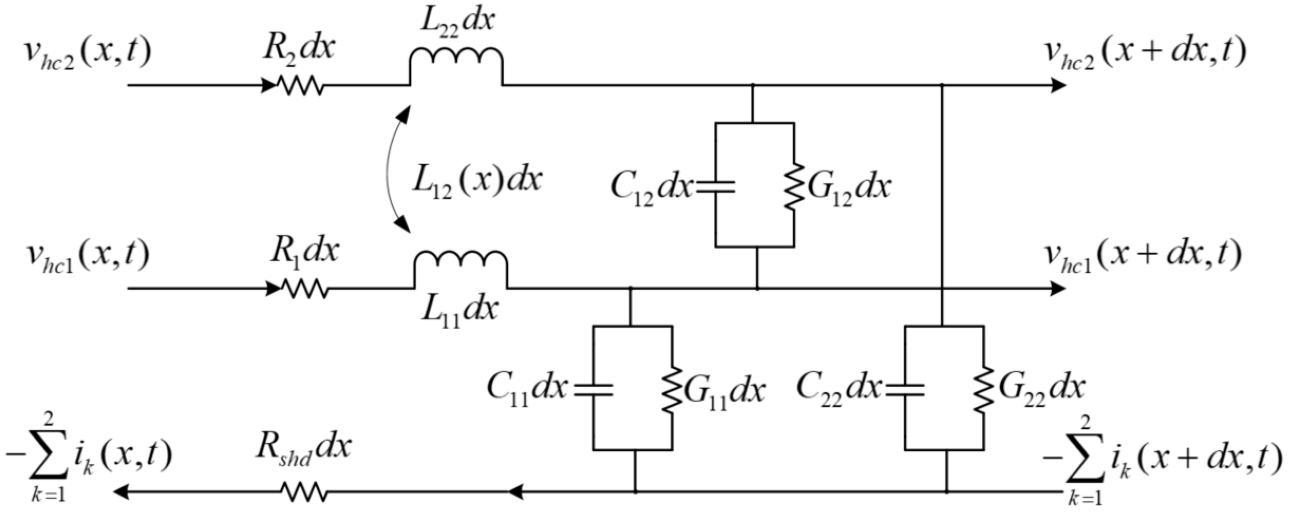
Figure 3.
Cross-section of the towed antenna with helix coil sensors.

Figure 4.
Experimental section of the towed antenna.

Figure 5.
Experimental platform for water flow cycling.
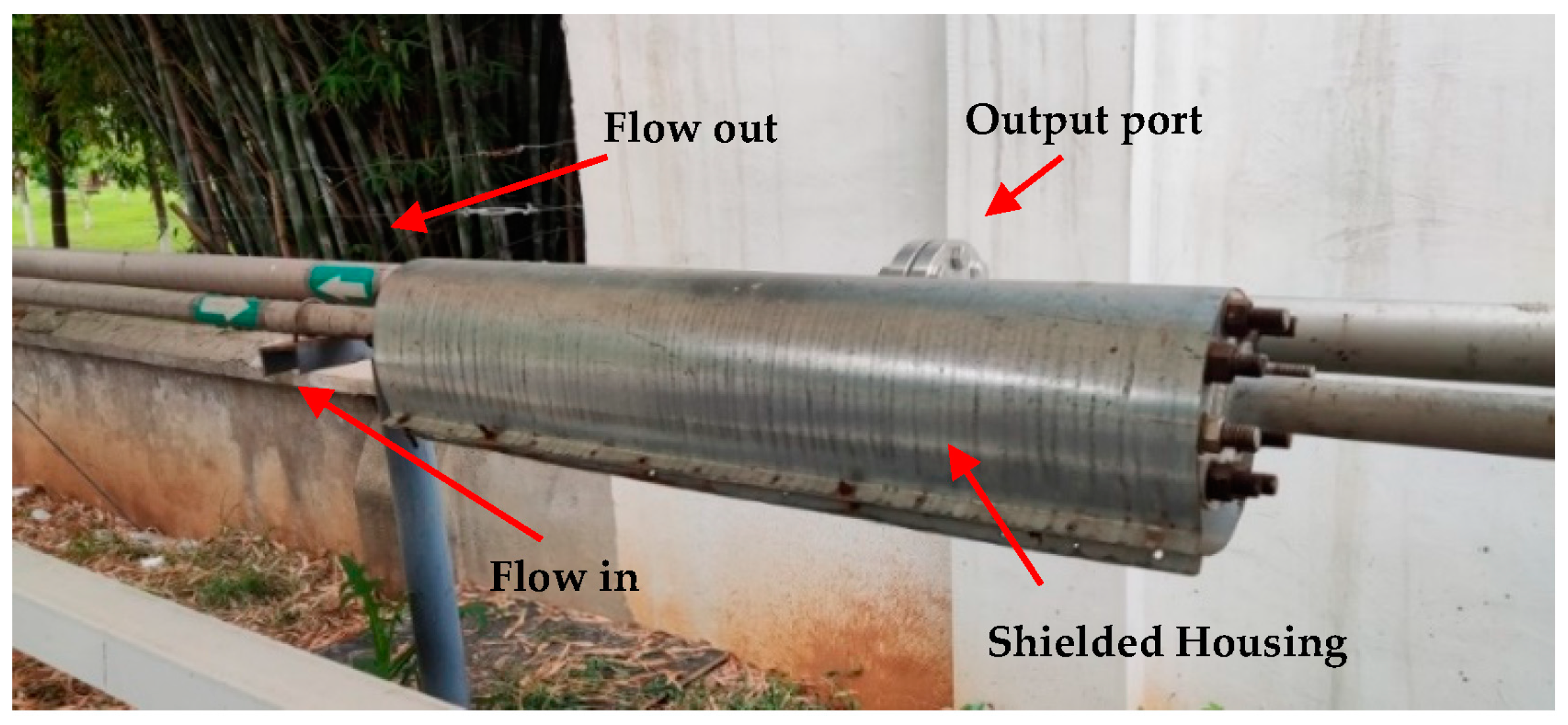
Figure 6.
Time domain of experimental section signals from static to vibrations.
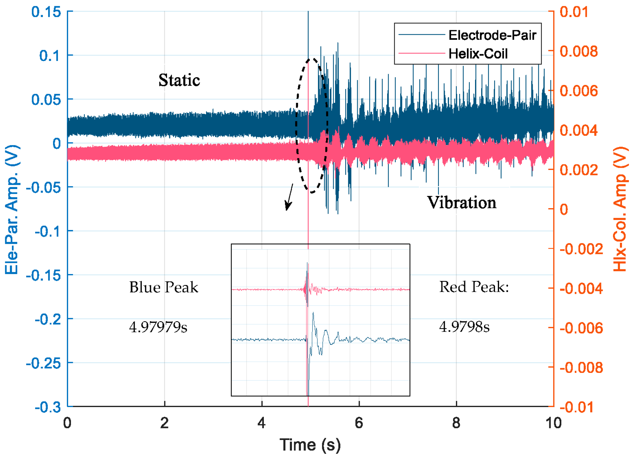
Figure 7.
Frequency domain of experimental section signals from static to vibrations.
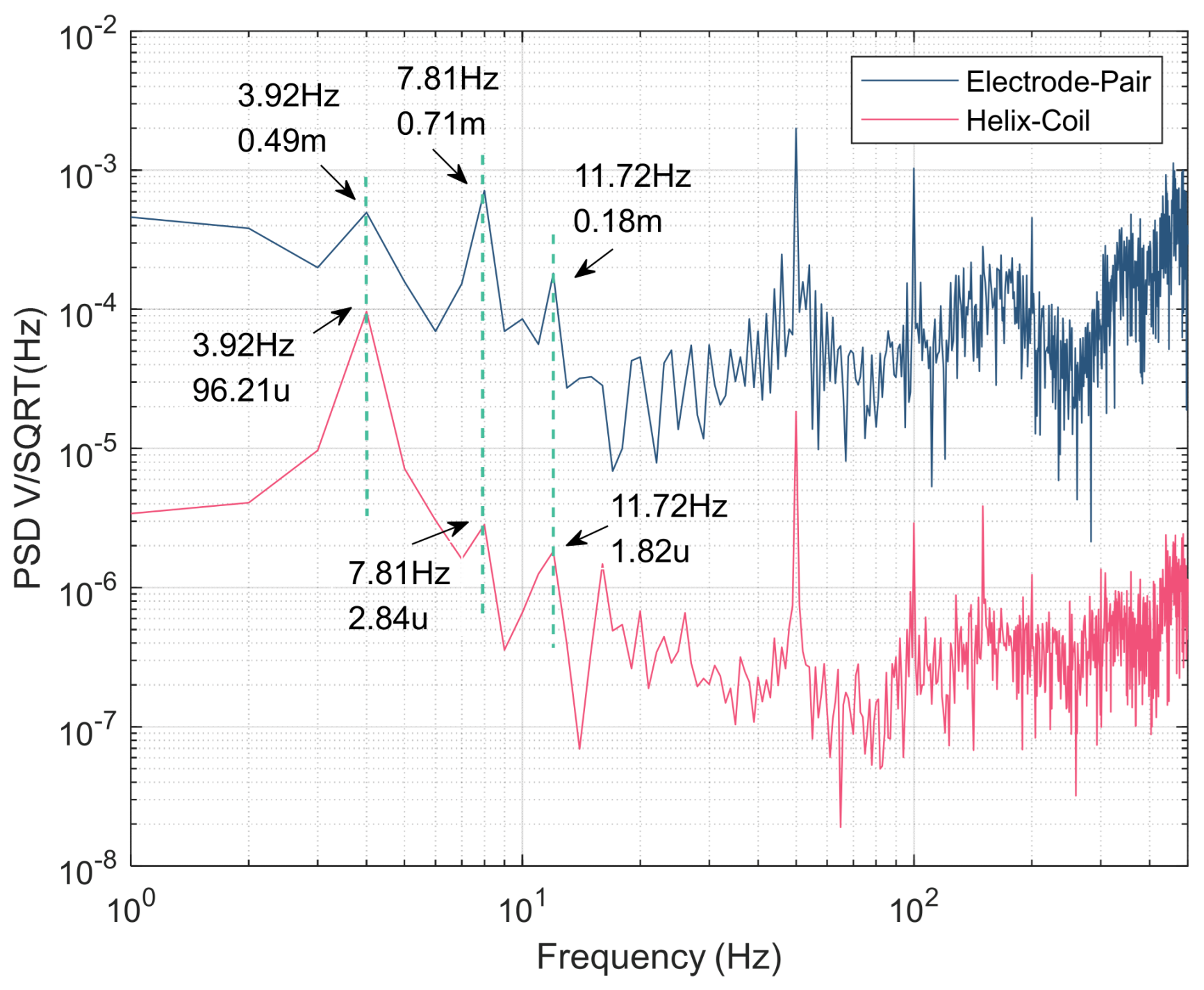
Figure 8.
Signals received in the time domain under various vibrations.
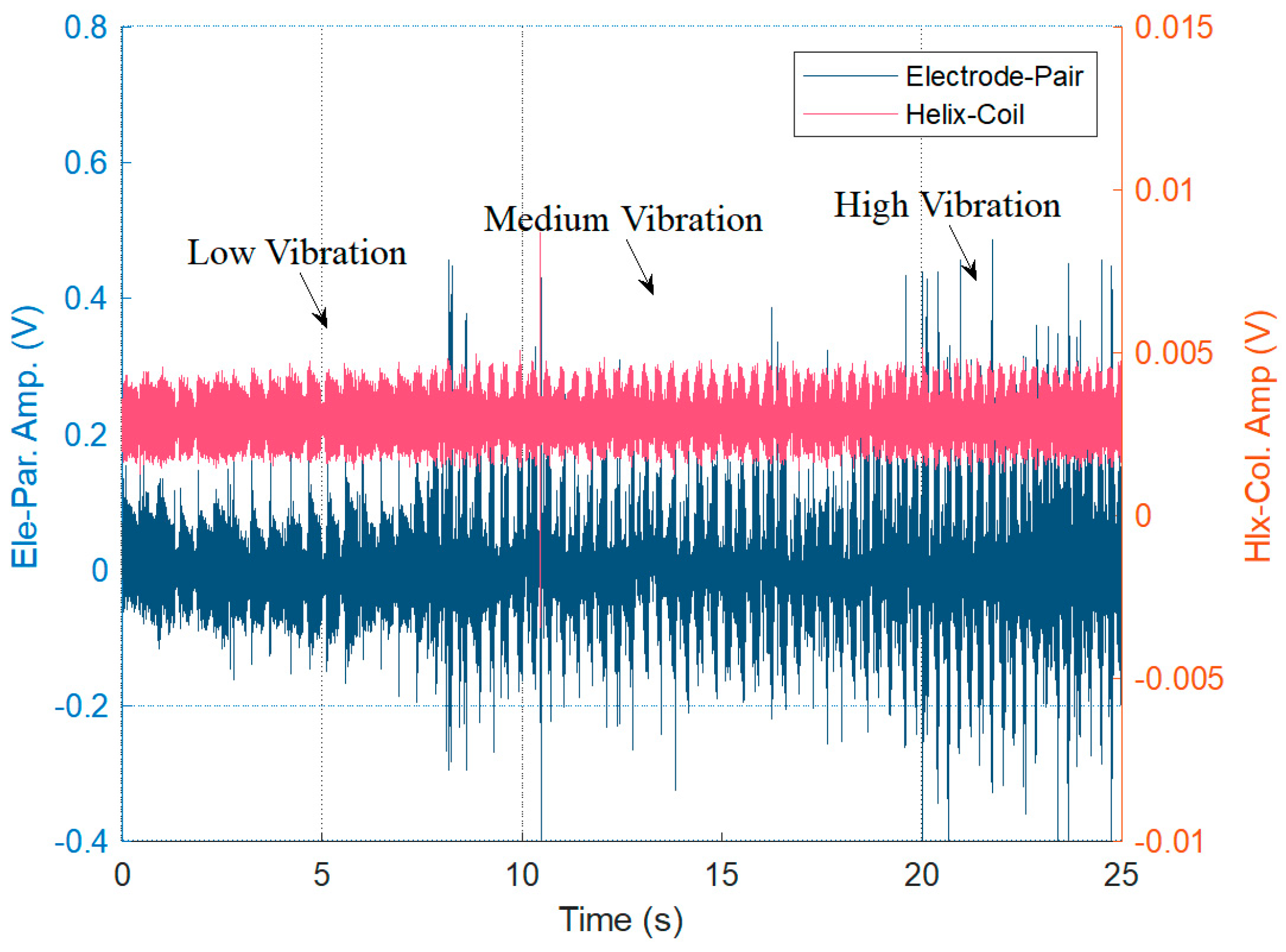
Figure 9.
Signals received in the frequency domain under various vibrations. (a) The PSD of electrode-pair. (b) The PSD of helix coil sensors.
Figure 9.
Signals received in the frequency domain under various vibrations. (a) The PSD of electrode-pair. (b) The PSD of helix coil sensors.
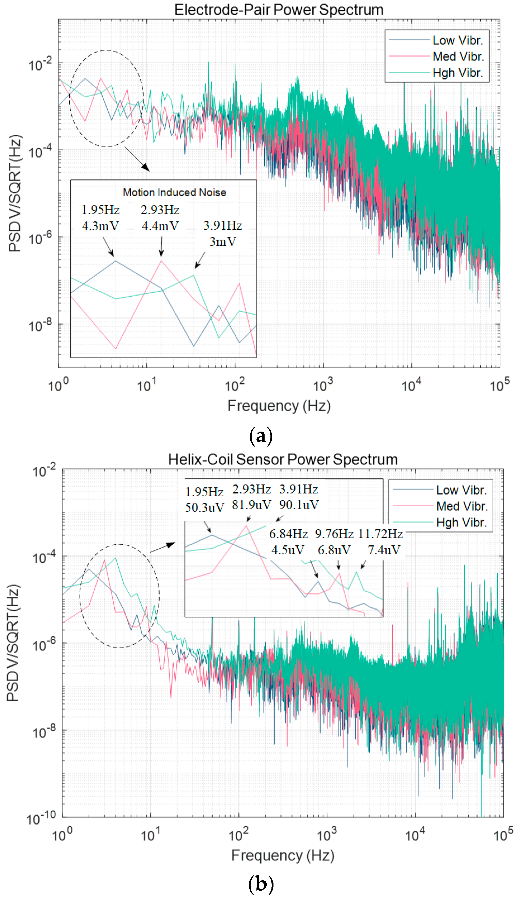
Figure 10.
Improved experimental section of the towed antenna.

Figure 11.
Received time domain signal normalizations from the improved experimental section.
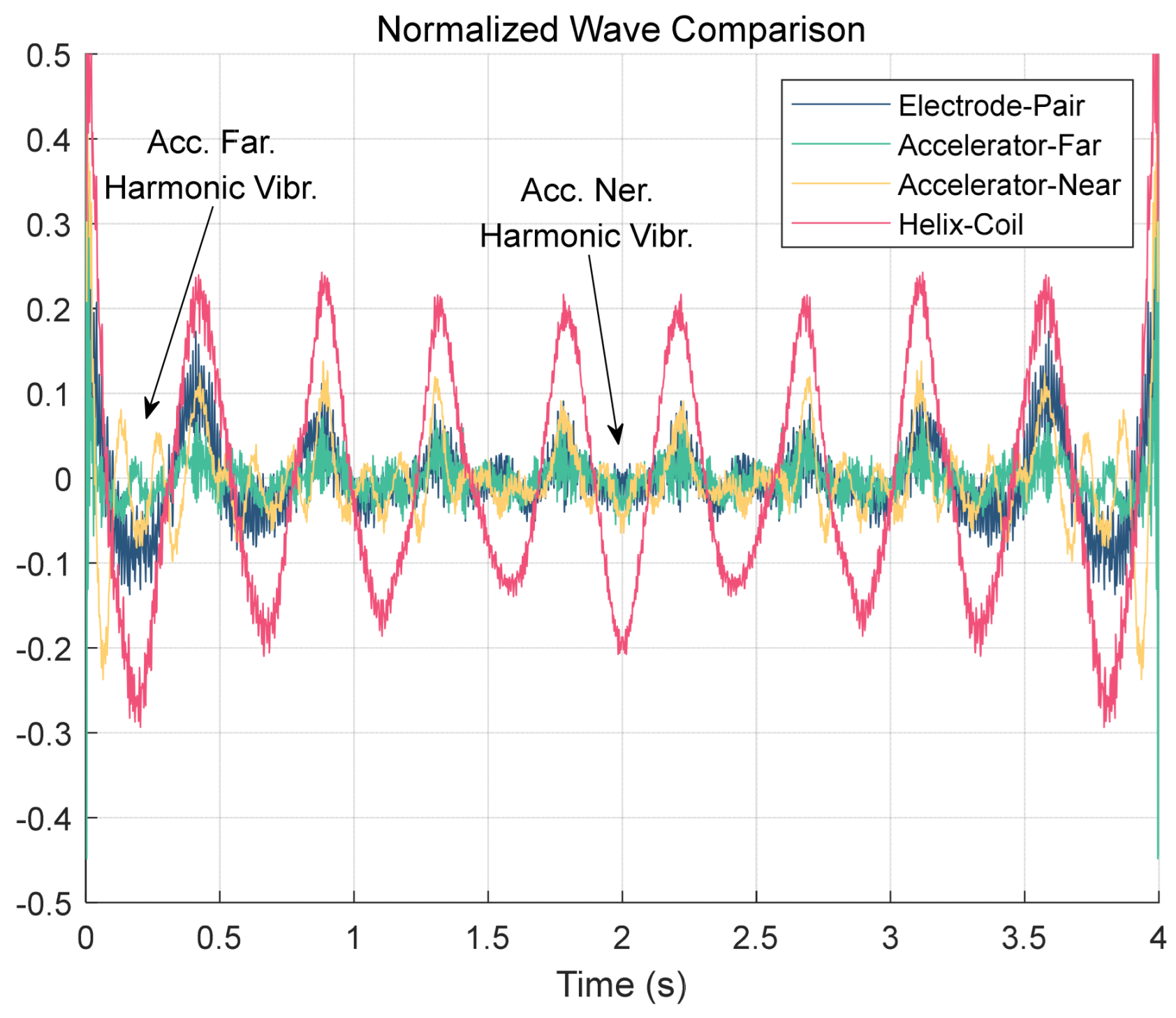
Figure 12.
Received frequency domain signals of the improved experimental section. (a) Low vibration speed. (b) Medium vibration speed. (c) High vibration speed.
Figure 12.
Received frequency domain signals of the improved experimental section. (a) Low vibration speed. (b) Medium vibration speed. (c) High vibration speed.


Table 1.
Experiment platform parameters.
| Components | Parameters | Value |
|---|---|---|
| Helix coil sensors | material | Copper |
| wire diameter | 0.5 mm | |
| winding diameter | 17.8 mm | |
| pitch | 11.5 mm | |
| coil turns | 80 | |
| Electrode-pair towed antenna | material | Stainless steel |
| electrode diameter | 18.5 mm | |
| electrode length | 60 mm | |
| distance | 1 m | |
| cable jacket | Polyethylene |
Table 2.
Experimental results of signal and noise varying with various vibrations.
| Antenna State | Time Domain (mV) | PSD (uV/Hz−1/2) | ||
|---|---|---|---|---|
| Ele-Par. Vpp | Hlx-Col. Vpp | Ele-Par. Vpp | Hlx-Col. Vpp | |
| Static | 48.38 | 0.81 | 220.21 | 1.43 |
| Low Vibr. | 241.24 | 2.97 | 738.45 | 4.28 |
| Med Vibr. | 460.41 | 3.27 | 992.19 | 6.02 |
| Hgh Vibr. | 814.91 | 3.53 | 1635.36 | 8.39 |
Table 3.
Correlation coefficient of electrode-pair towed antenna, helix coil sensors, and accelerators.
Table 3.
Correlation coefficient of electrode-pair towed antenna, helix coil sensors, and accelerators.
| Antenna State | re-h | re-f | re-n |
|---|---|---|---|
| Low Vibr. | 0.88 | 0.71 | 0.48 |
| 0.78 | 0.68 | 0.51 | |
| Med Vibr. | 0.94 | 0.83 | 0.66 |
| 0.84 | 0.91 | 0.71 | |
| Hgh Vibr. | 0.81 | 0.92 | 0.77 |
| 0.69 | 0.95 | 0.78 |
Disclaimer/Publisher’s Note: The statements, opinions and data contained in all publications are solely those of the individual author(s) and contributor(s) and not of MDPI and/or the editor(s). MDPI and/or the editor(s) disclaim responsibility for any injury to people or property resulting from any ideas, methods, instructions or products referred to in the content. |
© 2023 by the authors. Licensee MDPI, Basel, Switzerland. This article is an open access article distributed under the terms and conditions of the Creative Commons Attribution (CC BY) license (https://creativecommons.org/licenses/by/4.0/).
Share and Cite
MDPI and ACS Style
Xie, X.; Zuo, H.; Wei, S.; Wu, Q. Motion-Induced Noise Detection of Electrode-Pair Towed Antennas Using Helix Coil Sensors. Electronics 2023, 12, 1677. https://doi.org/10.3390/electronics12071677
AMA Style
Xie X, Zuo H, Wei S, Wu Q. Motion-Induced Noise Detection of Electrode-Pair Towed Antennas Using Helix Coil Sensors. Electronics. 2023; 12(7):1677. https://doi.org/10.3390/electronics12071677
Chicago/Turabian StyleXie, Xu, Hao Zuo, Shize Wei, and Qin Wu. 2023. "Motion-Induced Noise Detection of Electrode-Pair Towed Antennas Using Helix Coil Sensors" Electronics 12, no. 7: 1677. https://doi.org/10.3390/electronics12071677
Note that from the first issue of 2016, this journal uses article numbers instead of page numbers. See further details here.