
A Novel Architecture of a Six Degrees of Freedom Parallel Platform
by
 , , , , and
Qiuxiang Gu
1, 
Jiawei Tian
1,
Bo Yang
1,*,
Mingzhe Liu
2,*,
Borui Gu
3,
Zhengtong Yin
4,
Lirong Yin
5 and
Wenfeng Zheng
1,*
1
School of Automation, University of Electronic Science and Technology of China, Chengdu 610054, China
2
School of Data Science and Artificial Intelligence, Wenzhou University of Technology, Wenzhou 325000, China
3
Glasgow College, University of Electronic Science and Technology of China, Chengdu 611731, China
4
College of Resource and Environment Engineering, Guizhou University, Guiyang 550025, China
5
Department of Geography and Anthropology, Louisiana State University, Baton Rouge, LA 70803, USA
*
Authors to whom correspondence should be addressed.
Electronics 2023, 12(8), 1774; https://doi.org/10.3390/electronics12081774
Submission received: 28 March 2023
/
Accepted: 7 April 2023
/
Published: 9 April 2023
(This article belongs to the Special Issue Future AI and Robotics: Visual- and Spatial-Based Perception Enhancement and Reasoning)
Abstract
:With the rapid development of the manufacturing industry, industrial automation equipment represented by computer numerical control (CNC) machine tools has put forward higher and higher requirements for the machining accuracy of parts. Compared with the multi-axis serial platform solution, the parallel platform solution is theoretically more suitable for high-precision machining equipment. There are many parallel platform solutions, but not one can provide a common physical platform to test the effectiveness of a variety of control algorithms. To achieve the goals, this paper is based on the Stewart six degrees of freedom parallel platform, and it mainly studies the platform construction. This study completed the mechanical structure design of the parallel platform. Based on the microprogrammed control unit (MCU) + pre-driver chip + three-phase full bridge solution, we have completed the circuit design of the motor driver. We wrote the program of MCU to drive six parallel robotic arms as well as the program of the parallel platform control center on the PC, and we completed the system joint debugging. The closed-loop control effect of the parallel platform workspace pose is realized.
1. Introduction
With the advancement of science and the development of technology, the application of industrial robots and automation platforms has become an effective way to improve social productivity [1,2]. In the field of manufacturing and processing, the wide application of industrial robots not only improves production efficiency, but also helps enterprises save a lot on costs. Common robot platforms can be roughly divided into two types: serial platforms and parallel platforms according to the mechanical structure [3,4]. Compared with the series platform, the parallel platform has the advantages of no cumulative error and higher structural rigidity. The parallel platform has wider application scenarios and research value in the high-precision manufacturing fields, such as additive manufacturing based on 3D printing technology and CNC machining [5,6,7].
The Stewart parallel platform was first proposed by Dunlop researcher Gough as a tire pressure testing machine application [8]. The platform consists of three parts: a static platform at the bottom, a dynamic platform at the top, and six sets of parallel mechanical arms connecting the dynamic platform and the static platform. Each group of mechanical arms connects the bottom static platform and the top dynamic platform through the Hooke hinge. By adjusting the length of the six mechanical arms, the top moving platform can be controlled to achieve six degree of freedom attitude changes. The platform is applied to test the wear of tires under different conditions. It was not until 1965, when Stewart again proposed a six degree of freedom flight simulator with the same structure [9], that many scholars and engineers gradually realized the importance and superiority of this platform, and continued researching on the basis of Stewart’s thesis. In 1978, scholar Hunt discussed in detail the great potential of parallel structures in future applications. With the development of the theory of parallel platforms, the application of Stewart parallel platforms has gradually begun to be applied to satellite antennas, telescope positioning systems, pointing mechanisms, and vibration isolation equipment [10,11,12,13].
The parallel platform involves theoretical mechanics, statics, dynamics, mechanical engineering, control theory, electronic engineering, computer science, and other disciplines, and has great academic research value [14,15,16,17]. Most research on parallel platforms focus on the theoretical calculation and simulation of kinematics, dynamics, and controller [18,19,20,21]. However, there is currently a lack of a general physical platform that can test the performance of various control algorithms.
To complete a low-cost common physical platform that can be rebuilt in a low budget laboratory, we build the basic software and hardware platform. The hardware platform is mainly composed of two parts: a mechanical system and electronic system. In Section 3, this paper introduces the hardware design details of the parallel platform and completes the mechanical system of the parallel platform. This section also gives the schematic diagram of the hardware circuit of the servo driver. The program design scheme of the servo driver is presented in Section 4. The creation of the PC program of the parallel platform control center is detailed in Section 5. We test the system in Section 6, and finally conclude our study.
2. Architecture Design of the Control System
The six degree of freedom parallel platform needs complex mathematical operations, such as a six degree of freedom kinematics solution and motion control, and it also requires that the length of the six groups of robotic arms can be simultaneously adjusted [22,23,24]. Considering that the MCU frequency is typically in the tens to hundreds in the MHz range, this weak computing power cannot withstand this kind of computational pressure. The CPU frequency of the PC usually needs more than the GHz level, that can be used for high-intensity computing tasks. Therefore, the PC program is selected as the parallel platform control center in the architecture design of the scheme. The control center is responsible for completing the kinematics calculation and motion control, and uniformly dispatches the motion states of each group of robotic arms to ensure the synchronization of the motion of each robotic arm. The servo driver for adjusting the length of each group of mechanical arms is composed of a driver circuit and driver software with MCU as the core.
The servo motors of each group of robotic arms use brushless direct current (BLDC) motors [25,26]. A BLDC motor has the advantages of large torque, long life, and simple mechanical structure, that can fully meet the current closed-loop and speed closed-loop control requirements of this system. Through model selection and comparison, it was finally determined that we would use DJI RoboMaster M2006 P36 BLDC motor to provide power for the operation of the robotic arm. The architecture design of the parallel platform control system is shown in Figure 1:
In system structure diagram 1, the parallel platform control center receives the motion target information set by the user through the user interface (UI) and completes the trajectory planning. The control center adjusts the length of each robotic arm according to the preset trajectory, and finally moves the parallel platform to the target desired by the user. The control program first receives the BLDC motor’s real-time position information measured by the servo driver through the controller area network (CAN) bus, and calculates the length of each mechanical arm. Following the calculation of the length of the manipulator, the six degree of freedom pose and motion velocity of the parallel platform are calculated in real time through the kinematics forward solution algorithm. By comparing the real-time motion trajectory with the reference trajectory, the controller output of each robot arm at the current moment is calculated by an appropriate control algorithm, such as the model predictive control (MPC) and proportional plus integral (PI) controller, and sends the control output to the servo driver through the CAN bus. Each servo driver receives the control information at the current moment through the CAN bus, uses the field-oriented control (FOC) algorithm to control the BLDC motor’s movement [27,28,29], completes the length adjustment of the mechanical arm, and sends the BLDC motor’s operating angle information measured by the encoder through the CAN bus to the parallel platform control center. Such a structure can make full use of the high computing power of the PC to complete complex control operations, and complete real-time control in the driver to achieve better control effects. The overall operation process of the parallel platform control system is shown in Figure 2 below:
3. Hardware Design
The main goal of the hardware design of the parallel platform is to design six groups of manipulators that can complete the length adjustment and servo drives to control the manipulators. According to the design goal, the mechanical arm needs to complete the length adjustment task, so it is necessary to consider converting the rotational motion of the BLDC motor into linear motion during the design of the mechanical structure. In addition to completing the servo driver of the BLDC motor, the servo driver also needs to perform data interaction with the host computer. The design of the structural block diagram of the servo driver is shown in Figure 3:
It can be seen from Figure 3 that the circuit system is composed of several modules, such as MCU, power systems, drive and feedback modules, and communication system. Guided by the structural block diagram, the specific implementation of each module is elaborated in this section.
3.1. Mechanical Design of the Parallel Platform
For each group of robotic arms, it is necessary to design a mechanical structure that can convert the rotational motion of the BLDC motor into linear motion of the robotic arm. In addition, when the control center program solves the kinematics problem of the parallel platform and calculates the controller output, it also needs to obtain the length information of each mechanical arm. For the BLDC motor’s servo driver, although the length of the mechanical arm cannot be directly measured, the motor rotation angle can be obtained. Therefore, the designed mechanical structure needs to be able to quantify the relationship between the motor rotation angle and the length variation of the mechanical arm. Based on the above considerations, the structural design of the robotic arm is carried out, as shown in Figure 4 below:
The ① cylinder in Figure 4 is the BLDC motor. It is fixed to the mechanical arm through two screw holes, and is connected to the ② external thread screw through the locking mechanism. The ③ cylinder is an internal thread rod, and the thread pitch is equal to that of the ② external thread screw, both of which are 1.75 mm. When the ① motor rotates and drives the screw ② to rotate, the internal thread rod ③ can complete the axial displacement. Through this mechanical structure, the rotary motion of the motor can be converted into the linear motion of the mechanical arm. The special-shaped metal sheet ④ is fixed on the mechanical arm by bolts, and the oval gap on the left side is used to install the contact switch. When internal thread rod ③ shrinks to a certain position, the outer edge of the rod will touch the contact switch. At this time, the contact switch can obtain a signal, that is used to indicate that the mechanical arm returns to the zero position. During the initial calibration, when the contact switch with the signal is , the axial displacement is calculated according to the motor movement angle information, and the actual length of the mechanical arm can be calculated by . It should be noted that in the actual production, it is necessary to adjust all of the mechanical arms to the same length to reduce the error caused by the assembly of the mechanical arms.
We drew six sets of robotic arms using CATIA software, and connected them to the top and bottom platforms through universal joints. We completed the mechanical structure design of the six degree of freedom parallel platform, as shown in Figure 5:
3.2. MCU Circuit Design
Considering the system requirements comprehensively, the S32K144 automotive-grade chip of NXP is selected as the MCU of the servo driver hardware. The chip supports a 5 V power supply and has strong anti-interference performance. The core of the chip is based on the ARM Cortex-M4F, and the maximum operating frequency can reach 112 MHz. It also has the hardware floating-point unit (FPU) number calculation unit conforming to the IEEE-754 standard, that can satisfy the calculation performance required by the servo driver to complete the control algorithms, such as motor speed closed-loop control and current closed-loop control. The peripheral resources of the chip include two 8-channel synchronous PWM modules, that can realize the driving of a 2-channel BLDC motor, so the hardware circuits of the six BLDC motor’s servo drivers required by the system can be designed on three hardware circuit boards. The schematic diagram of the MCU control system circuit is shown in Figure 6:
3.3. Power System Design
Since the load of the servo driver is the BLDC motor, a large electromagnetic interference will be generated during the operation of the motor. Therefore, it is necessary to take this factor into consideration when designing the power system. The schematic diagram of the servo driver power supply circuit is shown in Figure 7:
In Figure 7, the power input is a 24 V constant-voltage direct current (DC) power supply, that is used to power the motor driver system and control system. U3 is a low dropout regulator (LDO) chip, that is used to convert the 24 V power supply to the 5 V voltage required by the control system. Since the BLDC motor switched from a motor to a generator during deceleration and braking [30,31], the 24 V DC bus voltage will increase and damage the driver hardware circuitry. For the safety of the hardware circuit system, eight 470 μF electrolytic capacitors are used to absorb the energy generated by the BLDC motor’s deceleration. A 33 V/8 kW bidirectional transient voltage suppression diode (TVS) D4 is connected between the power DC buses for voltage clamping. When the DC bus voltage is higher than 33 V, D4 will be broken down and turned on, and the DC bus voltage will be clamped to 33 V by releasing excess electric energy. Anti-surge resistors R11 and R12 and 33 V/900 W TVS diode D5 are designed for the digital chip power system as secondary protection. The cPWR in Figure 7 is the sampling point of the power supply voltage. The MCU can sample and calculate the real-time voltage value of the power supply through the voltage division ratio of the voltage dividing resistor. When the servo driver detects that the DC bus voltage is too high, the output function will turn off to protect the output system.
3.4. Driver System Design
The BLDC motor’s driver system consists of two parts: a pre-driver chip and a three-phase full-bridge circuit. This system selects TI’s DRV8305N pre-driver chip to drive the three-phase full bridge. The maximum operating voltage of the chip can reach 45 V, and it can provide a gate drive current of 1.25 A. The chip has three built-in differential amplifiers with adjustable magnification, that can amplify the BLDC motor’s sampling current to achieve high-precision sampling of the current. The protection function of the chip is also very complete, with various protection functions, such as power failure and overheating. The MCU can communicate with the pre-driver chip through the serial peripheral interface (SPI) bus to realize functions, such as configuring the working parameters of the motor and reading fault codes. The schematic diagram of the pre-driver chip circuit is shown in Figure 8:
The PWM wave boosted by the internal charge pump circuit of the pre-driver chip DRV8305N can directly drive the three-phase full-bridge metal-oxide-semiconductor field effect transistor (MOSFET). This system selects the AOD464 N-channel MOSFET with the maximum current of 40 A to form a three-phase full-bridge circuit. The schematic diagram of the circuit is shown in Figure 9:
The calculation and selection of the resistance value of the three-phase current sampling resistor is very important. If the sampling resistance is too small, the collected voltage signal will also be too small, that can be easily interfered by the motor noise signal, or even lost in the noise. However, if the sampling resistance is too large, the power consumed by the sampling resistance will increase, and the power of the motor will decrease. At the same time, more heat will accumulate at the sampling resistance, resulting in the risk of resistance melting.
Since the gain of the DRV8305N built-in current amplifier is 20, the relationship between the sampling voltage and the motor current is shown in Equation (1):
Among them, is the phase current of the three-phase motor, and is the resistance value of the sampling resistor. With a 5 V reference voltage, the 12-bit ADC voltage resolution is given by Equation (2):
Combining Formula (1) and Formula (2), the current resolution and maximum range of the MCU sampling system can be calculated as shown in Equation (3):
Assuming that the load current of the BLDC motor is when the motor is running, the total power of the drive system and the power consumed by the sampling resistor are shown in Equation (4):
At this time, the ratio of the sampling resistor power to the total system power is shown in Equation (5):
Select the sampling resistance as 10 milliohms, and take it into Equation (3) to obtain the current resolution of the MCU sampling system. The result is 6 mA and the maximum range is 24.576 A. Both the current resolution and the maximum range meet the requirements of the RoboMaster M2006 P36 BLDC motor’s driver. When the phase current reaches the maximum value of 24.576 A, the power consumed by the sampling resistor only accounts for 1.024% of the total power of the system when it is brought into the Equation (5). It can be seen from Equation (5) that the ratio of the sampling resistor to the total power will further decrease as the motor running phase current decreases. In summary, the resistance value of the sampling resistor is selected as 10 milliohms, that can meet the design requirements of the servo driver.
3.5. Communication System Design
The data that the servo driver needs to interact with the parallel platform control center includes the motor speed, the motor mechanical angle, and the motor controller output. The amount of data that needs to be communicated is not large, but the anti-jamming performance of the communication has higher requirements, so the communication system uses CAN bus communication. Because the MCU cannot directly meet the CAN bus physical layer and data link layer protocol defined by the ISO 11898 standard, this system uses the TJA1042T CAN transceiver chip to complete the logic level conversion. The schematic diagram of the CAN communication circuit is shown in Figure 10:
4. Servo Driver Program Design
The software development tool for the servo driver program of the parallel platform adopts the S32DS compilation and development environment of NXP Company. S32DS integrates many practical plug-ins and is developed based on an eclipse. The interface is simple and efficient, and can support coding, debugging, and programming of S32K full series chips. Among them, the Processor Expert plug-in can configure the general purpose input/output (GPIO), timer, analog to digital converter (ADC), pulse-width modulation (PWM), and other hardware peripheral resources through a graphical interface, that greatly improves the development efficiency of the embedded application software.
4.1. Main Function Programming
The program of the servo driver is mainly divided into two parts, the main function program and the interrupt service program. The main function program is used to initialize peripheral resources and control parameters, and complete the parameter calibration related to the BLDC motor. Check whether there is a CAN sending request in the main loop, and if so, send the CAN data to the host computer. The main function program flow chart is shown in Figure 11:
It can be seen from Figure 11 that after the ADC peripheral initialization is completed, the BLDC motor’s phase current bias calibration is performed first. The DRV8305N chip superimposes a DC bias voltage on the sampled phase current value. In order to avoid the chip bias voltage error from interfering with the phase current acquisition and calculation, the phase current offset calibration is required. The specific implementation method is: switch the shunt amplifier control register whose address is 0xA of DRV8305N to the DC calibration mode through SPI bus communication. Sample and store the ADC data in the DC calibration mode as DC bias voltage.
A magnetic encoder is a sensor used to measure the angle of a motor. The electrical angle of the motor can be calculated by sampling the voltage from the magnetic encoder output and calculating its arctangent using Equation (6):
Among them, and are the sine wave bias voltage and amplitude voltage, and are the cosine wave bias voltage and amplitude voltage, as shown in Equation (7):
The bias voltages and are used to restore the collected biased sinusoidal signals of the magnetic encoder to sinusoidal signals without bias voltage. The amplitude voltages and are used to normalize the amplitudes of the two sets of outputs to avoid errors caused by different output amplitudes. The magnetic encoder needs to be calibrated before use. The specific operation is: drive the motor to rotate and measure the maximum and minimum values of the encoder feedback voltage during the rotation. Complete the calibration of the bias voltage and amplitude voltage using Equation (7).
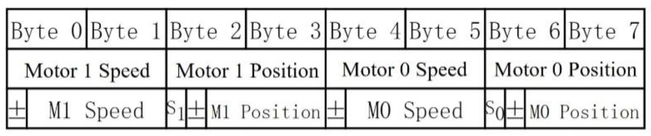
Following the calibration, the program enters the main loop. Upload the real-time speed and angle data of the motor to the parallel platform control center through the CAN bus in byte. Since the motor movement direction is divided into two directions, clockwise and counter clockwise, the position and speed information of the robotic arm uploaded by the driver board also has two forms, positive and negative. In order to transmit the negative value of the CAN bus data, the positive and negative signs of the data are expressed using 1 bit alone as the sign bit. In addition, 1 bit named is used as the trigger signal of the mechanical arm contact switch mentioned in Section 3.1. When the mechanical arm reaches the zero position, the servo driver can notify the host computer in time. The data format uploaded by the servo driver is shown in Figure 12:
The unit of velocity data is 0.1 mm/s, and the unit of position data is 0.1 mm. The number of pole pairs of the motor is seven pairs, and it is equipped with a 36:1 reduction box, and the thread pitch of the threaded rod is 1.75 mm. Therefore, the relationship between the length of the manipulator and the electrical angle of the motor is as in Equation (8):
Among them, is the cumulative electrical angle calculated from the reset point of the motor, and is the length of the mechanical arm when it is at the zero position. The servo driver sends the encoded data to the host computer through the CAN bus. The host computer uses the same method to receive and decode the data to obtain the current position and speed information of the robotic arm.
4.2. Interrupt Service Programming
The interrupt service program consists of three parts: CAN receive interrupt program, ADC interrupt program, and 10 mS timer interrupt program. The CAN receive interrupt program is used to update the BLDC motor’s control information sent by the host computer and stores it in FIFO, as the reference value of driver speed closed-loop control. The main function of the ADC interrupt program is to complete ADC data acquisition and perform the FOC current closed-loop control. The 10 mS timer interrupt program mainly completes the speed closed-loop task of the BLDC motor. The flow chart of the ADC interrupt program is shown in Figure 13:
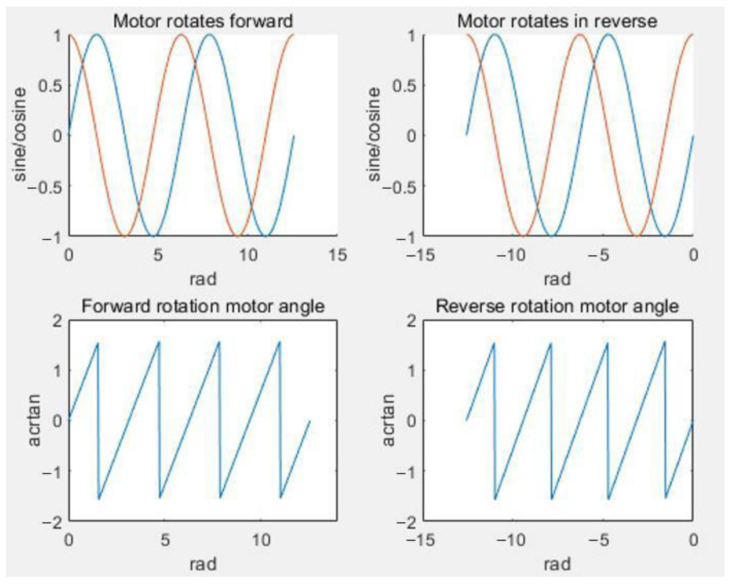
The phase current and encoder position can be obtained by sampling and calculating the ADC value. The collected data is filtered by four moving averages, that can reduce the influence of the motor noise while maintaining a certain sensitivity. The sampled magnetic encoder signal is brought into Equation (6) to calculate the current mechanical angle of the motor. Since the motor rotates continuously in the same direction, the change of its electrical angle is a periodic motion. The angle value calculated using the arctangent function will be recalculated from -π after exceeding π. The relationship between the magnetic encoder angle and the arctangent value is shown in Figure 14:
In order to obtain the accumulative rotation angle of the motor required by the system, it is necessary to process the angle data of the magnetic encoder obtained through direct calculation. It can be seen from Figure 14 that when the motor rotates forward and the angular value overflows, the sine wave output of the magnetic encoder reaches the maximum value. When the motor reverses and the angular value overflows, the sine wave output of the magnetic encoder reaches the minimum value. According to this characteristic of trigonometric function, the algorithm flow chart for processing the magnetic encoder angle is shown in Figure 15:
According to the physical structure of the three-phase BLDC motor, the electrical angle movement of the motor needs to go through at least six commutation states [32,33]. In the servo driver program, the real-time signal of the encoder is sampled each time before changing the commutation state. Therefore, every time the encoder angle calculation is performed, the electrical angle change of the motor will not exceed 2π/6.
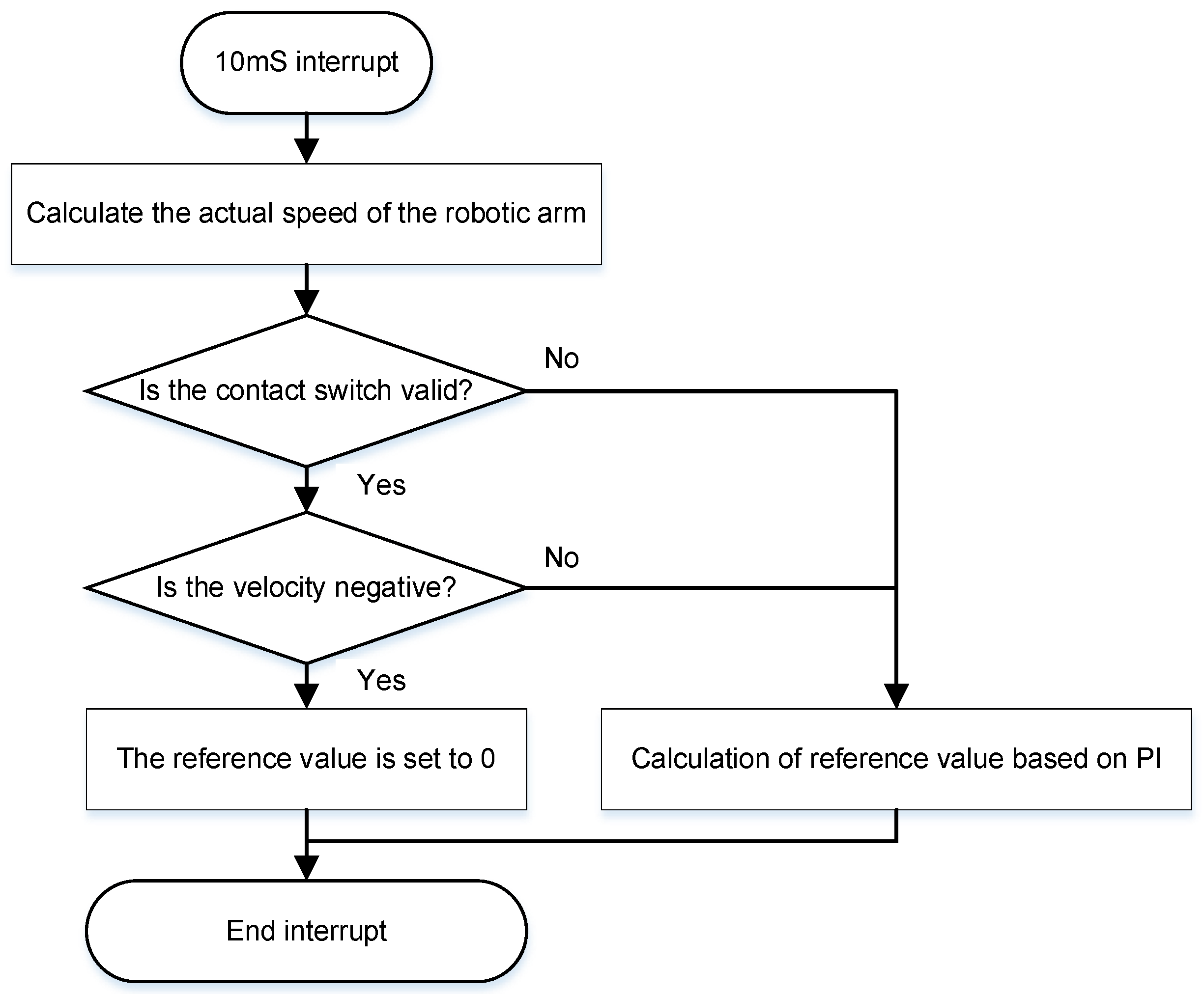
The 10 mS timer interrupt is used to calculate the real-time speed of the BLDC motor to complete the speed closed-loop control. The program flow chart is shown in Figure 16:
The limit switch is used as the mechanical zero position of the mechanical arm. Following the detection that the limit switch signal is turned on, the BLDC motor is prohibited from adjusting the length of the mechanical arm in the negative direction to ensure the safety of the mechanical structure. In other cases, the speed closed-loop control is completed according to the calculation result of the PI controller.
5. PC Software Design
The parallel platform control center realizes specific functions through the C++ program code under the Qt platform. The main tasks of the control center are communicating with the servo driver to complete the data exchange, and to obtain information on the length and speed of the mechanical arm. The kinematics forward solution calculation is completed through the position information of the mechanical arm uploaded by the six groups of drivers, and the attitude and attitude change speed of the parallel platform in the workspace are obtained. In the controller, the control output of each driver is calculated in combination with the reference trajectory and actual trajectory, and the control output is sent to each servo driver through the CAN bus.
In order to complete the kinematics forward and reverse solutions and the matrix calculation related to the motion controller, the Eigen, which is an open-source matrix calculation library, is used in the parallel platform control center program. For the task of data exchange with the servo driver, the USB-CAN analyzer device is selected. Complete the secondary development on the basis of the official dynamic link library ControlCAN.dll to realize the function of sending and receiving CAN message information through the USB interface. In order to intuitively display the attitude data of the physical parallel platform in the workspace, the drawing library QcustomPlot is used in the host computer program to complete the data visualization. Real-time display of the reference trajectory and actual running trajectory are obtained by trajectory planning.
In the program UI, at least three buttons are needed: start-up button, reset button, and run button. The start button is used to initialize the USB-CAN analyzer and create a CAN receiving thread. Initialize the matrix calculation parameters and start the 100 mS timer for the closed-loop control of the trajectory of the parallel platform. The 100 mS timer program flow chart is shown in Figure 17:
The reset button is used to send a reset command to all drivers, so that all robotic arms move to the reference mechanical zero position, and then move outward by 10 mm. At least one reset operation needs to be completed before the parallel platform motion control is performed. Otherwise, each servo driver will use the initial position when it is powered on as to calculate the length of the mechanical arm. At this time, the initial position is most likely not the real mechanical zero position of the robot arm. Therefore, the length information of the manipulator calculated according to will also be wrong. As a result, the control center cannot calculate the actual attitude of the parallel platform in the workspace.
The run button is used to complete the trajectory planning of the parallel platform workspace and to turn on the closed-loop adjustment function of the parallel platform. To make the platform more flexible, we designed two different closed-loop control modes: attitude control, that is used to make the parallel platform reach the target attitude with six specified axes, and the robotic arm control, that is used to adjust each robotic arm to obtain the specified length.
In order to ensure that each driver can execute the host computer command synchronously, it is necessary to avoid the time delay problem between the host computer command and each driver. CAN single-frame messages can send 8 bytes of data, and the number of the servo driver is six. Therefore, each byte can be used to represent a control output of a servo driver, and the host computer transmits the control output in the form of sending a broadcast message. The data structure of the sent CAN message is shown in Figure 18:
6. Tests and Results
When debugging the platform, a bottom-up debugging method is adopted. First complete the debugging of the BLDC motor’s servo driver to realize the basic functions of the driver. Then complete the assembly of each robotic arm and finally complete the motion control of the parallel platform.
6.1. Servo Driver Program Test
This part completes the current closed-loop control, speed closed-loop control, and CAN communication functions of the BLDC motor by debugging the servo driver program.
When the motor rotates, the two output channels of the magnetic encoder can generate sine and cosine signals, respectively. Use a digital oscilloscope to collect the signal waveform when the motor rotates, as shown in Figure 19:
According to the physical structure of the three-phase BLDC motor, the program selects π as the threshold. If the electrical angle change of the motor exceeds π, it is determined that an angle overflow has occurred and the angle is accumulated. Use the algorithm to drive the BLDC motor, and observe the current waveform of the BLDC motor’s operation on the oscilloscope, as shown in Figure 20:
From Figure 20a, it can be seen that the envelope of the current feedback waveform presents a sinusoidal waveform. As can be seen in Figure 20b, the sinusoidal envelope superimposes a square carrier at the same frequency as the driving PWM. In order to successfully sample the enveloped sine wave current, a low-pass filter is usually used to filter out high-frequency components and only keep low-frequency components. However, such an approach has certain defects: the frequency of the sinusoidal envelope feedback current is related to the rotation speed of the motor. As the motor speed increases, the frequency of the sine wave of the feedback current will also increase, and the low-pass filter will weaken the effective signal to a certain extent.
To accurately collect the required sinusoidal envelope signal, this system adopts the method of triggering the programmable delay module (PDB) by PWM, and then triggering the ADC by PDB for sampling. The trigger timing is shown in Figure 21:
It can be seen from Figure 21 that in the center-aligned mode of the PWM output channel, the PDB delay time is configured to be half of the PWM period. It can make the ADC sample the effective current every time during the PWM output. Signals sampled using this method are exactly on the sinusoidal envelope. A relatively stable BLDC motor’s current feedback signal can be obtained by using four sliding averages on the collected signal, that improves the accuracy and stability of the BLDC motor’s current feedback. In order to verify the correctness of the theory, we changed the level of the same GPIO port at each ADC sampling point. By measuring the timing of the GPIO port waveform and the current feedback waveform, it can be found that each ADC sampling occurs during the PWM output period, which is in line with the theoretical expectations. The image of the signal envelope and GPIO flip is shown in Figure 22:
6.2. The Actual Test of the Six Degree of Freedom Parallel Platform
In the control center, set the parallel platforms to work in the robotic arm length adjustment mode. The reset length of the robotic arm is 310 mm, and the L2 movement is set to 360 mm through the host computer. A magnetic encoder sensor obtains the real-time rotation angle of the BLDC motor, and use Equations (6)–(8) to calculate the L2 length. The length of the mechanical arm passes through the position closed-loop control of the host computer PI controller. To make sure the sensor and controller work normally, we measured the robotic arm’s displacement, as shown in Figure 23:
From the digital caliper in Figure 23b, it can be seen that the measured moving distance of L2 is consistent with the expected displacement, with only an error of 0.02 mm. On the basis of completing the debugging of a single group of robotic arms, continue to complete the assembly of the mechanical structure. The assembled six degree of freedom parallel platform is shown in Figure 24:
Figure 24 shows six sets of parallel robotic arms, as well as top and bottom platforms. The robotic arm is connected to the parallel platform through a universal joint. When the platform is assembled, it is necessary to adjust the connection position of the universal joint to make each robotic arm achieve the calibration of the initial length , so that it meets the kinematic parameters of the control system.
On the assembled parallel platform, each algorithm module of the control center is debugged in turn. Complete the kinematics inverse and forward solutions, the calculation of the Jacobian matrix of the parallel platform, and the PI controller and other functions. In this flexible platform, all of these algorithms can be easily replaced by other effective algorithms. The debugged control center has realized the attitude closed-loop control of the workspace of the parallel platform. The parallel platform can be moved to the target posture set by the user and displayed the results in the UI interface. Set the target attitude in the host computer interface of the control center, and the image for the attitude closed-loop control is shown in Figure 25:
The display interface in Figure 25 draws corresponding real-time images for the target attitude reference values in the six degrees of freedom directions and the real-time attitude data of the parallel platform. The horizontal axis is the time axis in seconds, the vertical axis in the displacement direction is in mm, and the vertical axis in the rotation direction is in degrees.
It can be seen from the figure that after 4 s of attitude closed-loop control, the real-time attitude of the parallel platform calculated by the host computer using the kinematics forward solution algorithm finally converges to the reference trajectory. The experiment proves that the PI controller, the Jacobian matrix, and other algorithms in the parallel platform control center work normally, and the real-time control output information can be calculated correctly. Send it to each driver through the CAN bus, and realize the closed-loop control of the length of each mechanical arm through the servo driver, and finally make the parallel platform reach the target attitude. In order to verify that the motion parameters obtained by the kinematics solution in the parallel platform control center are consistent with the motion state of the real object, we carried out the motion test of the 6 degrees of freedom directions of the parallel platform, and the images of the motions of each degree of freedom are shown in Figure 26:
7. Discussion and Conclusions
This study completed the construction of the parallel platform and the mechanical structure design of the parallel platform. Based on the S32K144 MCU, the schematic diagram of the BLDC motor’s three-phase servo driver and the program of the servo driver have been designed. We successfully completed the closed-loop control of the RoboMaster M2006 P36 three-phase BLDC motor. By using the PDB module to trigger ADC sampling, the influence of the modulated carrier on signal sampling was resolved. We completed the development of the GUI interface and algorithm of the parallel platform control center program in the host computer. We simultaneously controlled six sets of robotic arms through the CAN bus, achieving the attitude closed loop of the parallel platform workspace.
The test results show that the servo driver with current feedback and velocity feedback works normally, and the closed-loop control single robotic arm can obtain the target length with a low error. Other components of the parallel platform control center, such as the kinematics algorithm of the forward and inverse solution, the PI controller of the attitude control, the robotic arm control, and trajectory planning performed as expected. We successfully finished the trajectory tracking task of the physical parallel platform in the workspace.
In this research, we realized a physical platform with a low-cost solution and flexible structure. It can easily replace the component of the parallel platform control center to realize other algorithms and test their effectiveness [34].
Author Contributions
Conceptualization, W.Z. and B.Y; hardware, Q.G. and J.T.; software Q.G. and M.L.; validation, B.G.; formal analysis, Q.G. and J.T.; investigation, B.Y.; resources, M.L. and Z.Y; writing—original draft preparation, Q.G., J.T., Z.Y., and L.Y.; writing—review and editing, Z.Y., Q.G., W.Z., and L.Y.; visualization, Z.Y. and Q.G.; supervision, B.Y.; project administration, W.Z.; funding acquisition, W.Z. All authors have read and agreed to the published version of the manuscript.
Funding
Support by the Sichuan Science and Technology Program, 2021YFQ0003.
Institutional Review Board Statement
Not applicable.
Informed Consent Statement
Not applicable.
Data Availability Statement
The data presented in this study are available upon request from the corresponding author. The data are not publicly available as the experiment at the current stage is not at the level to be published.
Conflicts of Interest
The authors declare no conflict of interest.
Nomenclature
| CNC | (Computer numerical control) |
| MCU | (Microprogrammed control unit) |
| BLDC | (Brushless direct current) |
| UI | (User interface) |
| CAN | (Controller area network) |
| MPC | (Model predictive control) |
| PI | (Proportional plus integral) |
| FOC | (Field oriented control) |
| FPU | (Floating-point unit) |
| DC | (Direct current) |
| LDO | (Low dropout regulator) |
| SPI | (Serial peripheral interface) |
| MOSFET | (Metal-oxide-semiconductor field effect transistor) |
| GPIO | (General purpose input/output) |
| ADC | (Analog to digital converter) |
| PWM | (Pulse-width modulation) |
| PDB | (Programmable delay module) |
References
- Hua, X.; Li, H.; Zeng, J.; Han, C.; Chen, T.; Tang, L.; Luo, Y. A Review of Target Recognition Technology for Fruit Picking Robots: From Digital Image Processing to Deep Learning. Appl. Sci. 2023, 13, 4160. [Google Scholar] [CrossRef]
- Kim, E.; Shin, J.; Kwon, Y.; Park, B. EMG-Based Dynamic Hand Gesture Recognition Using Edge AI for Human–Robot Inter-action. Electronics 2023, 12, 1541. [Google Scholar] [CrossRef]
- Wang, X.; Zhang, D.; Zhao, C.; Zhang, P.; Zhang, Y.; Cai, Y. Optimal design of lightweight serial robots by integrating topology optimization and parametric system optimization. Mech. Mach. Theory 2018, 132, 48–65. [Google Scholar] [CrossRef]
- Liang, X.; Zeng, X.; Li, G.; Chen, W.; Su, T.; He, G. Design, Analysis, and Optimization of a Kinematically Redundant Parallel Robot. Actuators 2023, 12, 120. [Google Scholar] [CrossRef]
- Schiele, S.; Nguyen, T.N.; Lueth, T.C. Evaluating clearance parameters of 3D printed joints for the automated design of a non-assembly delta robot. In Proceedings of the 2021 IEEE International Conference on Robotics and Biomimetics (ROBIO), Sanya, China, 27–31 December 2021; pp. 583–588. [Google Scholar] [CrossRef]
- Cuellar, J.S.; Smit, G.; Plettenburg, D.; Zadpoor, A. Additive manufacturing of non-assembly mechanisms. Addit. Manuf. 2018, 21, 150–158. [Google Scholar] [CrossRef]
- Sun, Y.; Liu, Y.; Pancheri, F.; Lueth, T.C. LARG: A Lightweight Robotic Gripper With 3-D Topology Optimized Adaptive Fingers. IEEE/ASME Trans. Mechatronics 2022, 27, 2026–2034. [Google Scholar] [CrossRef]
- Gough, V.E. Contribution to discussion of papers on research in automobile stability, control and tyre performance. Proceeding Inst. Mech. Eng. 1956, 180, 392–394. [Google Scholar]
- Stewart, D. A platform with six degrees of freedom. Proc. Inst. Mech. Eng. 1965, 180, 371–386. [Google Scholar] [CrossRef]
- Furqan, M.; Suhaib, M.; Ahmad, N. Studies on Stewart platform manipulator: A review. J. Mech. Sci. Technol. 2017, 31, 4459–4470. [Google Scholar] [CrossRef]
- Yang, X.; Wu, H.; Chen, B.; Kang, S.; Cheng, S. Dynamic modeling and decoupled control of a flexible Stewart platform for vibration isolation. J. Sound Vib. 2018, 439, 398–412. [Google Scholar] [CrossRef]
- Taghizadeh, M.; Yarmohammadi, M.J. Development of a Self-tuning PID Controller on Hydraulically Actuated Stewart Platform Stabilizer with Base Excitation. Int. J. Control. Autom. Syst. 2018, 16, 2990–2999. [Google Scholar] [CrossRef]
- Jang, T.K.; Lim, B.S.; Kim, M.K. The canonical stewart platform as a six DOF pose sensor for automotive applications. J. Mech. Sci. Technol. 2018, 32, 5553–5561. [Google Scholar] [CrossRef]
- Pedrammehr, S.; Danaei, B.; Abdi, H.; Masouleh, M.T.; Nahavandi, S. Dynamic analysis of Hexarot: Axis-symmetric parallel manipulator. Robotica 2017, 36, 225–240. [Google Scholar] [CrossRef]
- Gallardo-Alvarado, J. A Gough–Stewart parallel manipulator with configurable platform and multiple end-effectors. Meccanica 2020, 55, 597–613. [Google Scholar] [CrossRef]
- Zhu, M.; Huang, C.; Song, S.; Gong, D. Design of a Gough–Stewart Platform Based on Visual Servoing Controller. Sensors 2022, 22, 2523. [Google Scholar] [CrossRef]
- Tripodo, C.; Lorenzi, S.; Cammi, A.; Miccichè, G. Object-oriented modeling, simulation and control of a 6-DoF parallel kinematic manipulator for remote handling in DONES facility. Fusion Eng. Des. 2022, 184, 113304. [Google Scholar] [CrossRef]
- Galván-Pozos, D.; Ocampo-Torres, F. Dynamic analysis of a six-degree of freedom wave energy converter based on the concept of the Stewart-Gough platform. Renew. Energy 2020, 146, 1051–1061. [Google Scholar] [CrossRef]
- Dai, X.; Song, S.; Xu, W.; Huang, Z.; Gong, D. Modal space neural network compensation control for Gough-Stewart robot with uncertain load. Neurocomputing 2021, 449, 245–257. [Google Scholar] [CrossRef]
- Chen, G.; Rui, X.; Abbas, L.K.; Wang, G.; Yang, F.; Zhu, W. A novel method for the dynamic modeling of Stewart parallel mechanism. Mech. Mach. Theory 2018, 126, 397–412. [Google Scholar] [CrossRef]
- Zhang, C. PD Plus Dynamic Pressure Feedback Control for a Direct Drive Stewart Manipulator. Energies 2020, 13, 1125. [Google Scholar] [CrossRef] [Green Version]
- Zhu, Q.; Zhang, Z. An Efficient Numerical Method for Forward Kinematics of Parallel Robots. IEEE Access 2019, 7, 128758–128766. [Google Scholar] [CrossRef]
- Cai, Y.; Zheng, S.; Liu, W.; Qu, Z.; Zhu, J.; Han, J. Sliding-mode control of ship-mounted Stewart platforms for wave compensation using velocity feedforward. Ocean Eng. 2021, 236, 109477. [Google Scholar] [CrossRef]
- Lafmejani, A.S.; Masouleh, M.T.; Kalhor, A. Trajectory tracking control of a pneumatically actuated 6-DOF Gough–Stewart parallel robot using Backstepping-Sliding Mode controller and geometry-based quasi forward kinematic method. Robot. Comput. Manuf. 2018, 54, 96–114. [Google Scholar] [CrossRef]
- Dat, N.T.; Van Kien, C.; Anh, H.P.H. Optimal FOC-PID Parameters of BLDC Motor System Control Using Parallel PM-PSO Optimization Technique. Int. J. Comput. Intell. Syst. 2021, 14, 1142. [Google Scholar] [CrossRef]
- Murali, M.; Arulmozhiyal, R. Investigation on modeling and simulation BLDC motor fed universal actuation system. Rev. Int. Métodos Numér. Cálc. Diseño Ing. 2021, 37, 10. [Google Scholar] [CrossRef]
- Nustes, J.C.; Pau, D.P.; Gruosso, G. Modelling the Field Oriented Control applied to a 3-phase Permanent Magnet Synchronous Motor. Softw. Impacts 2023, 15, 100479. [Google Scholar] [CrossRef]
- Tang, X.; Zhang, Z.; Liu, X.; Liu, C.; Jiang, M.; Song, Y. A Novel Field-Oriented Control Algorithm for Permanent Magnet Synchronous Motors in 60° Coordinate Systems. Actuators 2023, 12, 92. [Google Scholar] [CrossRef]
- Ghanayem, H.; Alathamneh, M.; Nelms, R.M. Decoupled Speed and Flux Control of Three-Phase PMSM Based on the Pro-portional-Resonant Control Method. Energies 2023, 16, 1053. [Google Scholar] [CrossRef]
- Gałuszkiewicz, P.; Gałuszkiewicz, Z.; Baran, J. Simulation Studies of Energy Recovery in a BLDC Motor-Based Kinetic Energy Storage. Energies 2022, 15, 7494. [Google Scholar] [CrossRef]
- Godfrey, A.J.; Sankaranarayanan, V. A new electric braking system with energy regeneration for a BLDC motor driven electric vehicle. Eng. Sci. Technol. Int. J. 2018, 21, 704–713. [Google Scholar] [CrossRef]
- Inayathullaah, M.A.; Sivakumar, N.; Balasundaram, A.; Arul, R.; Angalaeswari, S. Time Domain Investigation of Hybrid In-telligent Controllers Fed Five-Phase PMBLDC Motor Drive. Appl. Sci. 2023, 13, 3281. [Google Scholar] [CrossRef]
- Tu, X.; Bu, W.; Zeng, Q. Research on the Modelling of a Single-winding Bearingless Permanent Magnet Brushless DC Motor. J. Phys. Conf. Ser. 2021, 1887, 012049. [Google Scholar] [CrossRef]
- Liu, M.; Gu, Q.; Yang, B.; Yin, Z.; Liu, S.; Yin, L.; Zheng, W. Kinematics Model Optimization Algorithm for Six Degrees of Freedom Parallel Platform. Appl. Sci. 2023, 13, 3082. [Google Scholar] [CrossRef]
Figure 1.
The overall structure of the parallel platform control system.

Figure 2.
Functional design block diagram of the parallel platform control system.

Figure 3.
Block diagram of the driver hardware structure.

Figure 4.
Mechanical structure diagram of the robotic arm.

Figure 5.
Mechanical structure design of the six degree of freedom parallel platform.

Figure 6.
Schematic diagram of the MCU control system circuit.

Figure 7.
Schematic diagram of the servo driver power supply circuit.

Figure 8.
DRV8305N circuit schematic diagram.

Figure 9.
Schematic diagram of the three-phase full-bridge circuit.

Figure 10.
Schematic diagram of the CAN communication circuit.

Figure 11.
Main function program flow chart.

Figure 12.
Servo driver data upload format.

Figure 13.
ADC interrupt program flow chart.

Figure 14.
Magnetic encoder angle and motor angle.

Figure 15.
Flow chart of the magnetic encoder angle calculation.

Figure 16.
The 10 mS timer interrupt flow chart.

Figure 17.
Flow chart of the trajectory closed-loop control program.

Figure 18.
CAN send data format of the host computer.

Figure 19.
The oscilloscope collects the output of the magnetic encoder when the motor is rotating.

Figure 20.
The wave of the BLDC motor’s current feedback; (a) 20 ms scale waveform; (b) 500 us scale waveform.
Figure 20.
The wave of the BLDC motor’s current feedback; (a) 20 ms scale waveform; (b) 500 us scale waveform.

Figure 21.
PWM and PDB trigger timing.

Figure 22.
Signal envelope and GPIO flip image; (a) 1 ms scale waveform; (b) 200 us scale waveform.

Figure 23.
Closed-loop control of the arm length; (a) L2 set movement 50 mm; (b) L2 measured movement 50.02 mm.
Figure 23.
Closed-loop control of the arm length; (a) L2 set movement 50 mm; (b) L2 measured movement 50.02 mm.

Figure 24.
The physical six degree of freedom parallel platform.

Figure 25.
Attitude closed-loop control image.

Figure 26.
Six degrees of freedom attitude closed-loop control of the parallel platform; (a) translate along the x-axis; (b) translate along the y-axis; (c) translate along the z-axis; (d) rotate along the x-axis; (e) rotate along the y-axis; (f) rotate along the z-axis.
Figure 26.
Six degrees of freedom attitude closed-loop control of the parallel platform; (a) translate along the x-axis; (b) translate along the y-axis; (c) translate along the z-axis; (d) rotate along the x-axis; (e) rotate along the y-axis; (f) rotate along the z-axis.

Disclaimer/Publisher’s Note: The statements, opinions and data contained in all publications are solely those of the individual author(s) and contributor(s) and not of MDPI and/or the editor(s). MDPI and/or the editor(s) disclaim responsibility for any injury to people or property resulting from any ideas, methods, instructions or products referred to in the content. |
© 2023 by the authors. Licensee MDPI, Basel, Switzerland. This article is an open access article distributed under the terms and conditions of the Creative Commons Attribution (CC BY) license (https://creativecommons.org/licenses/by/4.0/).
Share and Cite
MDPI and ACS Style
Gu, Q.; Tian, J.; Yang, B.; Liu, M.; Gu, B.; Yin, Z.; Yin, L.; Zheng, W. A Novel Architecture of a Six Degrees of Freedom Parallel Platform. Electronics 2023, 12, 1774. https://doi.org/10.3390/electronics12081774
AMA Style
Gu Q, Tian J, Yang B, Liu M, Gu B, Yin Z, Yin L, Zheng W. A Novel Architecture of a Six Degrees of Freedom Parallel Platform. Electronics. 2023; 12(8):1774. https://doi.org/10.3390/electronics12081774
Chicago/Turabian StyleGu, Qiuxiang, Jiawei Tian, Bo Yang, Mingzhe Liu, Borui Gu, Zhengtong Yin, Lirong Yin, and Wenfeng Zheng. 2023. "A Novel Architecture of a Six Degrees of Freedom Parallel Platform" Electronics 12, no. 8: 1774. https://doi.org/10.3390/electronics12081774
Note that from the first issue of 2016, this journal uses article numbers instead of page numbers. See further details here.