

Ultracompact SIRC-Based Self-Triplexing Antenna with High Isolation


1
Engineering Optimization and Modeling Center, Reykjavik University, 102 Reykjavik, Iceland
2
Faculty of Electronics, Telecommunication and Informatics, Gdansk University of Technology, 80-233 Gdansk, Poland
*
Author to whom correspondence should be addressed.
Electronics 2023, 12(9), 2112; https://doi.org/10.3390/electronics12092112
Submission received: 13 March 2023
/
Revised: 20 April 2023
/
Accepted: 4 May 2023
/
Published: 5 May 2023
(This article belongs to the Special Issue Recent Advances in Antennas and Millimeter-Wave Applications for Mobile Communication Systems)
Abstract
:An ultracompact self-triplexing antenna realized on a substrate-integrated rectangular cavity (SIRC) is discussed in this study. The proposed structure employs two L-shaped slots and an inverted U-shaped slot to radiate at three independent operating frequency bands. Three 50-ohm microstrip feed lines were used to excite the radiation in these slots. The operating frequency was individually tuned using the slot size. The slot placement and size were designed having in mind considering obtaining one or more frequency bands below the SIRC cutoff frequency, which had the advantage of enabling an ultracompact size. High port isolation was achieved by applying one of the ports orthogonally to the two remaining ones, which created a weak cross-coupling channel. A lumped-circuit model was created to examine the antenna operation. The presented design has been prototyped and experimentally validated with the measured operating frequencies of 1.92 GHz, 4.43 GHz, and 5.25 GHz for GSM, 5G, and WLAN applications, respectively. The port isolations are better than 32.4 dB according to both EM simulations and measurements. Meanwhile, the measured realized gain of the antenna is better than 4.3 dBi at all bands.
1. Introduction
Personal communication devices frequently employ multiband communication systems. Usually, these systems have two or more wireless transceivers for a variety of applications. Multiband antennas are typically utilized instead of multiple antennas to deliver better performance for transceivers. It is challenging to arrange antenna components tightly in a limited space while maintaining adequate isolation between them. One method for enhancing input port isolation is a decoupling network [1]. However, as a result, the size of the circuitry increases, limiting its applicability for handheld devices.
Therefore, current research has focused on creating multiband antennas, with monopole-, slot-, and SIW-based structures being the most prevalent architectures [2,3,4,5,6,7,8,9,10,11]. A rectangular monopole truncated patch loaded with a U-shaped slot was employed for the design of a tri-band millimeter-wave antenna in [2]. In [3], a monopole dual-band antenna was realized by applying a microstrip resonant-cell-based low-pass filter feed. A multiband antenna was designed by using the ground plane radiation mode in [4]. A triband dual-polarized antenna was constructed by using cross-shaped slots and L-shaped slots in [5]. A triband antenna was developed based on a substrate-integrated waveguide (SIW) loaded with a pair of open-loop slots in [7]. In [8], a triband antenna was realized on a half-mode SIW loaded with multiple slots. A quarter-mode SIW cavity loaded with multiple slots was employed to design a triband antenna [9]. In [10], a triangular SIW cavity loaded with slots was applied to build a wearable antenna. A rectangular loop and a rectangular slot were used to construct a planar antenna-triplexer in [11]. At each working frequency, the aforementioned designs provide strong in-band performance, and the structures are small. However, when used with several transceivers, a single-input arrangement becomes a deficiency. To facilitate connectivity between several transceivers and the multiband antenna, frequency-selective devices, such as a diplexer or triplexer, are needed because the differences in frequency interfere with other transceiver circuits. However, this new component will take up more space, and the design will become complex. Many researchers have suggested the construction of self-diplexing [12,13,14,15,16,17,18,19,20,21,22,23,24], self-triplexing [25,26,27], or self-multiplexing [28,29,30] antennas to reduce the required area and to improve isolation.
Substrate-integrated waveguide (SIW) technology has recently become an attractive alternative for constructing planar self-multiplexing antennas [12,13,14,15,16,17,18,19,20,21,22,23,24,25,26,27,28,29,30]. A self-diplexing antenna (SDA) was realized based on the SIW cavity-backed transverse slots in [12]. A self-diplexing antenna involving SIW cavity-backed bowtie-ring slots has been reported in [13]. In [14], the construction of a self-diplexing antenna using a shielded-quarter mode SIW loaded with a Y-shaped slot was described. By attaching two U-shaped slots to the top of the SIW cavity, a self-diplexing antenna was created in [15]. In [16], a rectangular SIW cavity-based asymmetric cross-shaped slot antenna was designed for circularly polarized applications. A self-diplexing antenna was constructed in [17] using square SIW cavity-backed stepped patches. In [18], a high-isolation self-diplexing antenna was developed using a cavity-backed U-shaped slot. A quarter-mode SIW was employed to design an ultracompact SDA [19]. In [20], a tunable SDA based on an SIW cavity loaded with open-ended slots was proposed. Rectangular and triangular radiating patches were employed on the SIW to realize a high isolation SDA in [21]. In [22], a shielded quarter-mode SIW cavity was employed to design an SDA with high isolation. An ultracompact SDA was developed by using a shielded quarter-mode SIW [23]. In [24], a tunable SIW-based SDA was constructed by employing microfluidic channels.
Although the aforementioned SDA structures work effectively, the design of self-triplexing or self-multiplexing antennas should be investigated further. Based on different SIW cavities, several self-triplexing antennas (STAs) [25,26,27] and self-multiplexing antennas (SMAs) [28,29,30] have been realized. In [25], an STA was built based on an SIW cavity loaded with two bowtie slots. Two SIW cavities, one of which is incorporated within the other, have been used to build a self-triplexing antenna [26]. In [27], a self-triplexing antenna was designed using a square SIW cavity loaded with a modified I-shaped slot. In [28], a substrate-integrated rectangular cavity was used to create a self-quadruplexing antenna. A self-hexaplexing antenna based on a substrate-integrated rectangular cavity loaded with two Pi-shaped slots was constructed [29]. In [30], a self-multiplexing antenna (SMA) was constructed using a rectangular SIW cavity loaded with modified radiating patches. Despite the satisfactory performance of the aforementioned antenna topologies, designing a highly miniaturized self-triplexing antenna featuring high port isolation remains a strenuous endeavor.
This paper presents an ultracompact self-triplexing antenna constructed on a substrate-integrated rectangular cavity (SIRC). Two L-shaped slots and an inverted U-shaped slot were used by the proposed structure to radiate at three separate operational frequency bands. The operating frequency can be independently altered using the slot size. For validation, a prototype was manufactured and tested at 1.94 GHz, 4.4 GHz, and 5.3 GHz. As demonstrated by both EM simulations and measurements, the isolations were better than 32.4 dB. The observed realized gains of the antenna are greater than 4.3 dBi. The unique technical contributions of the work are as follows:
- (i)
- A systematic design approach for SIRC cavity-based slot antennas is presented.
- (ii)
- We suggest, fabricate, and test an ultracompact single-layer tri-band antenna with high isolation and gain in all three bands.
- (iii)
- The proposed STA configuration exhibits a highly miniaturized footprint area.
- (iv)
- It is possible to tune all three bands independently without disturbing the other radiating frequency bands.
- (v)
- For a better comprehension of the working principle of the proposed STA, an equivalent lumped-circuit model is developed.
- (vi)
- Port one is orthogonally connected to ports two and three, resulting in a very weak cross-coupling path between ports and increased isolation. As a result, all three ports achieve excellent isolation of greater than 32.42 dB.
2. Development and Analysis of the Proposed SIRC-Based Self-Triplexing Antenna
2.1. Antenna Configuration
Figure 1 shows the layout of an ultracompact self-triplexing antenna (STA). The proposed STA uses a substrate-integrated rectangular cavity (SIRC), a U-shaped slot (USS), two L-shaped slots (LSS), and three microstrip feed lines. The design steps followed to realize the STA are shown in Figure 2. In Step 1, an SIRC with the dimensions of 26 mm × 34 mm is designed to operate at 4.65 GHz in the fundamental mode (TE110). In Step 2, three microstrip 50 Ω lines are used to feed the cavity to obtain a self-triplexing property. The matching at each port is obtained by employing inline feeds. Since port 1 is orthogonal to ports 2 and port 3, a very weak cross-coupling path is formed that enables maximum port isolation. In Step 3, an inverted U-shaped slot (USS) is created on the top plane and excited by port 1, resulting in the first radiating frequency band and an isolation greater than 20 dB. 1. The resonant frequency of the fundamental mode is shifted towards a lower value as a result of the suggested U-shaped slot loading. This reduction in resonant frequency from the SIW cut-off frequency results in an ultracompact antenna footprint. This provides a size reduction factor of 80.4% for the suggested STA. Finally, two L-shaped slots (LSS) are attached to both sides of the USS, which results in the generation of two more radiating bands and provides freedom to control the isolation level. These slots create a very weak cross-coupling path between ports, which results in isolation greater than 32 dB. The suggested STA is optimized using CST Microwave Studio to operate at 1.92 GHz, 4.43 GHz, and 5.25 GHz. For a better understanding of the radiation mechanism, the surface current density at each port is demonstrated, as shown in Figure 3. It can be inferred from the figure that the maximum current flows through the port that has been excited, and almost negligible current passes through the other ports.
2.2. Equivalent Lumped-Circuit Model
The working principle of the STA was explained by developing an equivalent lumped-circuit model (LCM), as presented in Figure 4. The cavity-backed radiating aperture is expressed as shunt-connected resistance (Rxj), capacitance (Cxj), and inductance (Lxj), with j = 1, 2, and 3 standing for ports 1, 2, and 3, respectively. The U-shaped slot provides extra capacitive loading that is represented as shunt-connected capacitance (Cy1), which is responsible for producing the first radiation frequency. The L-shaped slots excited by ports 2 and 3 provide extra capacitive loadings, which are expressed as the shunt-connected capacitances Cy2 and Cy3, respectively. These capacitive loadings are responsible for the second and third radiating frequencies. Since the capacitances Cy1, Cy2, and Cy3 depend on the geometry of the USS and LSS, the radiating frequencies can be controlled by altering the corresponding slot dimensions. Series-connected inductance (Lk) and capacitance are used to describe the mutual connections between the ports (Ck). Impedance matching between cavity-backed patches and feed lines is accomplished using impedance transformers. The Keysight Advanced Design System simulates the proposed equivalent network model, and Table 1 lists the optimized component values. Figure 5 displays the circuit and simulated EM reflection coefficients.
2.3. Independent Frequency Tunability
The proposed STA operating at 1.92 GHz, 4.43 GHz, and 5.25 GHz is suitable for, but not limited, to Global System for Mobile Communications (GSM), 5G, and WLAN applications. However, the dimensions of inverted U-shaped and L-shaped slots can be varied to tune the operating frequencies f01 (1.93 GHz to 2.80 GHz), f02 (4.16 GHz to 5.60 GHz), and f03 (4.36 GHz to 5.73 GHz), which support various applications such as WiFi, Bluetooth, Extended PCS, 5G, WiMAX, and WLAN wireless standards. The frequency tunability range in relation to the design parameters and supporting application bands is shown in Table 2. It is clear that the suggested STA is appropriate for a variety of communication standards. Parametric studies were carried out with respect to the radiating patch height to establish a broad concept of independent control of the resonant frequencies, as shown in Figure 6. The heights of Lx, Ly, and Lz corresponding to USS and LSS are employed for the tunability of fo1, fo2, and fo3, respectively. From Figure 6, it can be inferred that the radiating frequency increases by decreasing the height of the radiating apertures. Referring to Figure 6a, the radiating frequency fo1 increases from 1.93 GHz to 2.80 GHz by decreasing the height Lx from 23.09 mm to 15.09 mm. When the height Ly decreases from 10.35 mm to 6.35 mm, the operating frequency fo2 increases from 4.16 GHz to 5.60 GHz, as depicted in Figure 6b. From Figure 6c, it is found that by decreasing the height from 10.13 mm to 6.63 mm, the radiating frequency increases from 4.36 GHz to 5.73 GHz. Moreover, it can be concluded that when one of the frequency bands is changed, the other bands remain unaffected.
3. Fabrication, Measurement, and Results Discussion
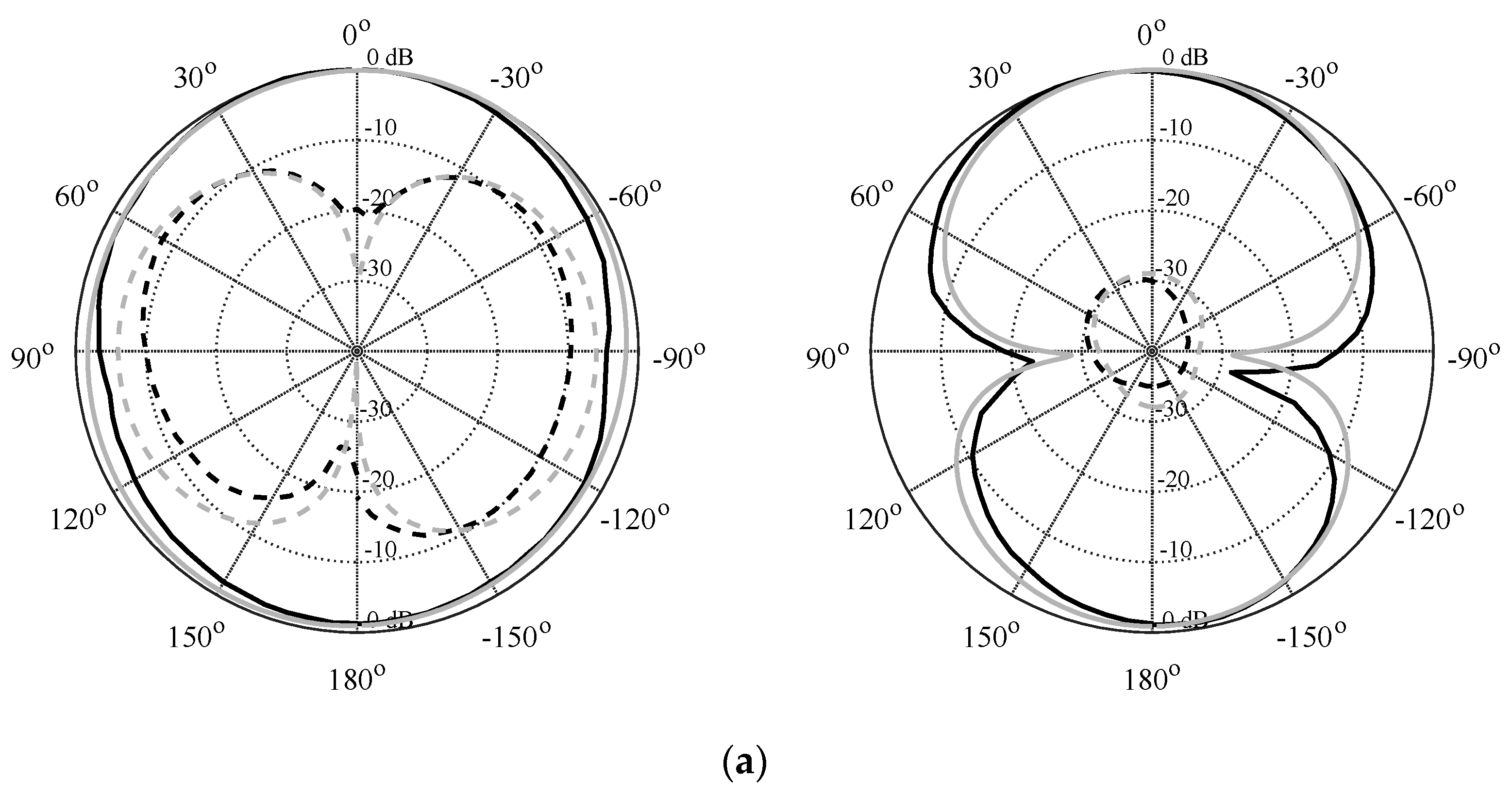
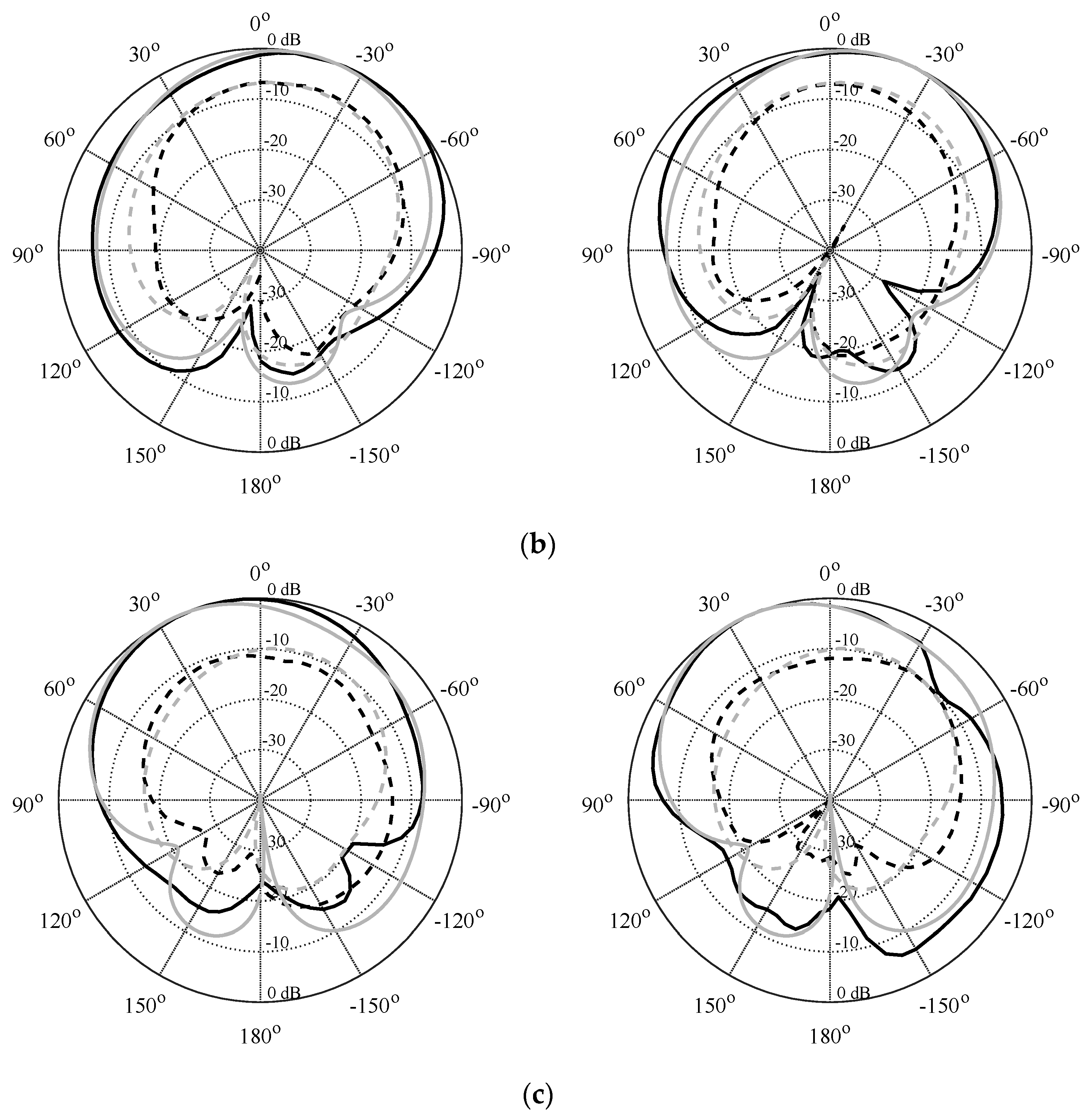
As a proof of concept, a prototype of the self-triplexing antenna (STA) based on the SIRC was devised, manufactured, and experimentally validated. The prototype was fabricated on a low-loss 0.762 mm thick Arlon AD250 substrate with a permittivity of 2.5 and a loss tangent of 0.0014. The proposed STA is ultracompact with a size smaller than 0.086λg2. Photographs of the STA prototype and the experimental setup are displayed in Figure 7 and Figure 8, respectively. The comparison between the EM-simulated and tested S-parameters is shown in Figure 9. The measured reflection coefficients were recorded as −24.11 dB, −28.76 dB, and −25.73 dB, whereas the EM simulated reflection coefficients were obtained as −29.03 dB, −37.6 dB, and −49.5 dB at 1.92 GHz, 4.43 GHz, and 5.25 GHz, respectively. The port isolations for the EM simulation and experiment were greater than 32.42 dB at each band, as shown in Figure 10. Considering a 10 dB reflection coefficient level, the measured impedance bandwidths were computed as 0.93%, 1.17%, and 1.88%, whereas the EM simulated impedance bandwidths were found to be 1.36%, 1.58%, and 1.89% at 1.92 GHz, 4.43 GHz, and 5.25 GHz, respectively. As the narrow band is coming, we can use it for pinpoint applications in the mentioned commercial wireless application band, such as Global Systems for Mobile Communications (GSM) (at 1.92 GHz), 5G (at 4.43 GHz), and WLAN (at 5.25 GHz). If a thicker substrate with the same dielectric constant is utilized, then the bandwidth and the radiation efficiency will increase [31,32,33]. Farfield radiation patterns were observed and recorded in an automatic anechoic chamber. A single port was excited at each measurement, with the remaining ports terminated using a matched 50-ohm load. The estimated realized gains and EM-simulated radiation efficiencies are shown in Figure 11 and Figure 12, respectively. In Figure 11, the measured realized gains are recorded as 4.10 dBi, 5.59 dBi, and 4.94 dBi, whereas the EM simulated realized gains are calculated as 3.8 dBi, 5.3 dBi, and 4.86 dBi at 1.92 GHz, 4.43 GHz, and 5.25 GHz, respectively. A small discrepancy was found between the tested and EM-simulated realized gains. The deviation was attributed to the precision of the radiating aperture, imperfection of substrate properties, fabrication, and SMA connector. However, the deviation of the realized gains is less than 7.31%, 5.18%, and 1.62% at center frequencies of 1.92 GHz, 4.43 GHz, and 5.25 GHz, respectively. Referring to Figure 12, it was discovered that the proposed STA’s radiation efficiency was higher than 82% across all bands. Table 3 provides an overview of the measured reflection coefficients, isolations, realized gains, and EM simulated radiation efficiencies. Figure 13 shows the normalized radiation patterns of the proposed STA. Linear polarization and unidirectional patterns were obtained using the STA prototype. As expected, an overall excellent agreement between the LCM model results, the EM simulation results, and the measurement results was observed. Nevertheless, minor differences were noticed, resulting from the connection loss and manufacturing tolerances.
Table 4 shows a performance comparison analysis of the proposed STA and previously published STAs or triband antennas. The proposed STA achieves an ultracompact size, high isolation, and excellent realized gain, according to the table. The proposed STA has a smaller footprint area than those in [2,5,7,10,11,25,26,27]. Furthermore, the suggested STA is 50% smaller than the most compact STA reported in [27], and there is no significant difference in the realized gains. The proposed STA has a minimum port isolation of 32.4 dB across all bands, which is greater than the isolation level obtained in previously documented antennas [2,5,7,10,11,25,26,27]. It should be mentioned that the proposed STA includes a lumped-circuit model to analyze the antenna’s working principle, whereas, with the exception of [26], no lumped-circuit model was provided for antenna analysis in [2,5,7,10,11,25,27]. These findings indicate that the proposed STA is potentially more attractive for use in triband wireless communication networks.
4. Conclusions
This work introduced an ultracompact self-triplexing antenna realized on a substrate-integrated rectangular cavity (SIRC). For transmission in three distinct operational frequency bands, the proposed antenna employs two L-shaped slots and an inverted U-shaped slot. To stimulate the radiation in these slots, three 50-ohm microstrip feed lines were utilized. The operating frequency can be individually controlled using the slot size. The slot arrangement and size were chosen with the purpose of obtaining one or more frequency bands below the SIRC cutoff frequency, which allowed for an ultracompact size. High port isolation was achieved by connecting one port orthogonally to two other ports, resulting in a weak cross-coupling channel. To explain the operating principles of the proposed antenna, a lumped-circuit model was developed and analyzed. The proposed antenna was prototyped and experimentally validated at 1.92 GHz, 4.43 GHz, and 5.25 GHz for GSM, 5G, and WLAN applications, respectively. The prototype was manufactured using a low-loss 0.762 mm thick Arlon AD250 substrate with a relative permittivity of 2.5. In the EM simulations and tests, the isolations were more than 30 dB. The estimated realized gains for the suggested antenna are more than 4.1 dBi. The agreement between the full-wave EM analysis results and experimental data is satisfactory with respect to all antenna characteristics. The proposed antenna structure is suitable for a number of applications, which include the Global System for Mobile Communications (GSM), 5G mobile technology, and WLAN applications, among others. Upon appropriate changes in antenna dimensions, it can also support a broad range of other applications, such as WiFi, Bluetooth, Extended PCS, and WiMAX.
Author Contributions
Conceptualization, R.K.B. methodology, R.K.B. and S.K.; software, R.K.B. and S.K.; validation, R.K.B. and S.K.; formal analysis, R.K.B.; investigation, R.K.B.; resources, S.K.; data curation, R.K.B. and S.K.; writing—original draft preparation, R.K.B.; writing—review and editing, S.K.; visualization, R.K.B. and S.K.; supervision, S.K.; project administration, S.K.; funding acquisition, S.K. All authors have read and agreed to the published version of the manuscript.
Funding
The research leading to these results has received funding from the Norway Grants 2014-2021 via the National Centre for Research and Development, grant NOR/POLNOR/HAPADS/0049/2019-00. This work was also supported in part by the Icelandic Centre for Research (RANNIS) Grant 217771.
Data Availability Statement
Not applicable.
Acknowledgments
The authors would like to thank Dassault Systemes, France, for making CST Microwave Studio available.
Conflicts of Interest
The authors declare no conflict of interest.
References
- Chen, S.C.; Wang, Y.S.; Chung, S.J. A decoupling technique for increasing the port isolation between two strongly coupled antennas. IEEE Trans. Antennas Propag. 2008, 56, 3650–3658. [Google Scholar] [CrossRef]
- Ahmad, S.; Boubakar, H.; Naseer, S.; Alim, M.E.; Sheikh, Y.A.; Ghaffar, A.; Al-Gburi, A.J.A.; Parchin, N.O. Design of a Tri-Band Wearable Antenna for Millimeter-Wave 5G Applications. Sensors 2022, 22, 8012. [Google Scholar] [CrossRef]
- Wang, D.; Chan, C.H. Multiband antenna for WiFi and WiGig communications. IEEE Antennas Wirel. Propag. Lett. 2015, 15, 309–312. [Google Scholar] [CrossRef]
- Anguera, J.; Andújar, A.; García, C. Multiband and small coplanar antenna system for wireless handheld devices. IEEE Trans. Antennas Propag. 2013, 61, 3782–3789. [Google Scholar] [CrossRef]
- Cui, Y.; Wang, X.; Shen, G.; Li, R. A triband SIW cavity-backed differentially fed dual-polarized slot antenna for WiFi/5G applications. IEEE Trans. Antennas Propag. 2020, 68, 8209–8214. [Google Scholar] [CrossRef]
- Bozzi, M.; Georgiadis, A.; Wu, K. Review of substrate-integrated waveguide circuits and antennas. IET Microw. Antennas Propag. 2011, 5, 909–920. [Google Scholar] [CrossRef]
- Zheng, Z.; Li, D.; Tan, X.; Chen, Q. Single-Layer Dual-/Tri-band SIW Filtenna Based on Multifunctional Cavity-Backed Slots. IEEE Trans. Antennas Propag. 2023, 71, 4498–4503. [Google Scholar] [CrossRef]
- Niu, B.J.; Tan, J.H. Half-mode SIW cavity antenna for tri-band MIMO applications. Microw. Opt. Technol. Lett. 2020, 62, 1697–1701. [Google Scholar] [CrossRef]
- Niu, B.J.; Tan, J.H. Compact tri-band MIMO antenna based on quarter-mode slotted substrate-integrated-waveguide cavity. Int. J. RF Microw. Comput.-Aided Eng. 2020, 30, e22101. [Google Scholar] [CrossRef]
- Mandal, B.; Parui, S.K. Wearable tri-band SIW based antenna on leather substrate. Electron. Lett. 2015, 51, 1563–1564. [Google Scholar] [CrossRef]
- Cheong, P.; Chang, K.F.; Choi, W.W.; Tam, K.W. A highly integrated antenna-triplexer with simultaneous three-port isolations based on multi-mode excitation. IEEE Trans. Antennas Propag. 2014, 63, 363–368. [Google Scholar] [CrossRef]
- Nandi, S.; Mohan, A. An SIW cavity-backed self-diplexing antenna. IEEE Antennas Wirel. Propag. Lett. 2017, 16, 2708–2711. [Google Scholar] [CrossRef]
- Barik, R.K.; Cheng, Q.S.; Dash, S.K.; Pradhan, N.C.; Subramanian, K.S. Design of a compact orthogonal fed self-diplexing bowtie-ring slot antenna based on substrate integrated waveguide. Int. J. RF Microw. Comput.-Aided Eng. 2020, 30, e22422. [Google Scholar] [CrossRef]
- Pradhan, N.C.; Subramanian, K.S.; Barik, R.K.; Cheng, Q.S. A shielded-QMSIW-based self-diplexing antenna for closely spaced bands and high isolation. IEEE Antennas Wirel. Propag. Lett. 2021, 20, 2382–2386. [Google Scholar] [CrossRef]
- Barik, R.K.; Koziel, S.; Cheng, Q.S.; Szczepanski, S. Highly Miniaturized Self-Diplexed U-Shaped Slot Antenna Based on Shielded QMSIW. IEEE Access 2021, 9, 158926–158935. [Google Scholar] [CrossRef]
- Priya, S.; Kumar, K.; Dwari, S.; Mandal, M.K. Circularly polarized self-diplexing SIW cavity backed slot antennas. IEEE Trans. Antennas Propag. 2019, 68, 2387–2392. [Google Scholar] [CrossRef]
- Dash, S.K.K.; Cheng, Q.S.; Barik, R.K.; Pradhan, N.C.; Subramanian, K.S. A compact substrate integrated self-diplexing antenna for WiFi and ISM band applications. In Proceedings of the 50th European Microwave Conference (EuMC), Utrecht, The Netherlands, 12–14 January 2021; pp. 232–235. [Google Scholar]
- Barik, R.K.; Cheng, Q.S.; Dash, S.K.K.; Pradhan, N.C.; Karthikeyan, S.S. Compact high-isolation self-diplexing antenna based on SIW for C-band applications. J. Electromagn. Waves Appl. 2020, 34, 960–974. [Google Scholar] [CrossRef]
- Iqbal, A.; Al-Hasan, M.; Mabrouk, I.B.; Nedil, M. Ultracompact quarter-mode substrate integrated waveguide self-diplexing antenna. IEEE Antennas Wirel. Propag. Lett. 2021, 20, 1269–1273. [Google Scholar] [CrossRef]
- Iqbal, A.; Tiang, J.J.; Lee, C.K.; Mallat, N.K. SIW cavity backed self-diplexing tunable antenna. IEEE Trans. Antennas Propag. 2021, 69, 5021–5025. [Google Scholar] [CrossRef]
- Dash, S.K.K.; Cheng, Q.S.; Barik, R.K.; Khan, T.; Subramanian, K.S. A compact dual-fed highly isolated SIW based self-diplexing antenna. AEU-Int. J. Electron. Commun. 2021, 132, 153613. [Google Scholar] [CrossRef]
- Pradhan, N.C.; Subramanian, K.S.; Barik, R.K.; Dalal, P.; Cheng, Q.S. Design of Compact Shielded QMSIW Based Self-Diplexing Antenna for High-Isolation. In Proceedings of the IEEE Wireless Antenna and Microwave Symposium (WAMS), Rourkela, India, 5–8 June 2022; pp. 1–4. [Google Scholar]
- Pradhan, N.C.; Sholampettai, S.K.; Barik, R.K.; Cheng, Q.S. A shielded QMSIW ultra-compact self-diplexing antenna for WiMAX/WLAN applications. J. Electromagn. Waves Appl. 2022, 36, 1869–1881. [Google Scholar] [CrossRef]
- Pradhan, N.C.; Reddy, M.G.; Subramanian, K.S.; Barik, R.K.; Koziel, S.; Cheng, Q.S. Microfluidic SIW-Based Tunable Self-Diplexing Antenna for Sub-6 GHz Band Applications. IEEE Trans. Circuits Syst. II Express Briefs 2022, 70, 1435–1439. [Google Scholar] [CrossRef]
- Kumar, K.; Dwari, S. Substrate integrated waveguide cavity-backed self-triplexing slot antenna. IEEE Antennas Wirel. Propag. Lett. 2017, 16, 3249–3252. [Google Scholar] [CrossRef]
- Iqbal, A.; Selmi, M.A.; Abdulrazak, L.F.; Saraereh, O.A.; Mallat, N.K.; Smida, A. A compact substrate integrated waveguide cavity-backed self-triplexing antenna. IEEE Trans. Circuits Syst. II Express Briefs 2020, 67, 2362–2366. [Google Scholar] [CrossRef]
- Dash, S.K.K.; Cheng, Q.S.; Barik, R.K.; Pradhan, N.C.; Subramanian, K.S. A compact triple-fed high-isolation SIW-based self-triplexing antenna. IEEE Antennas Wirel. Propag. Lett. 2020, 19, 766–770. [Google Scholar] [CrossRef]
- Barik, R.K.; Koziel, S. Highly-Miniaturized Self-Quadruplexing Antenna Based on Substrate-Integrated Rectangular Cavity. IEEE Antennas Wirel. Propag. Lett. 2023, 22, 482–486. [Google Scholar] [CrossRef]
- Barik, R.K.; Koziel, S. A Compact Self-Hexaplexing Antenna Implemented on Substrate-Integrated Rectangular Cavity for Hexa-Band Applications. IEEE Trans. Circuits Syst. II Express Briefs 2023, 70, 506–510. [Google Scholar] [CrossRef]
- Dash, S.K.K.; Cheng, Q.S.; Barik, R.K.; Jiang, F.; Pradhan, N.C.; Subramanian, K.S. A compact SIW cavity-backed self-multiplexing antenna for hexa-band operation. IEEE Trans. Antennas Propag. 2021, 70, 2283–2288. [Google Scholar] [CrossRef]
- Harrington, R.F. Effect of antenna size on gain, bandwidth, and efficiency. J. Res. Natl. Bur. Stand. Sect. D Radio Propag. 1960, 64, 1–12. [Google Scholar] [CrossRef]
- Luo, G.Q.; Hu, Z.F.; Dong, L.X.; Sun, L.L. Planar slot antenna backed by substrate integrated waveguide cavity. IEEE Antennas Wirel. Propag. Lett. 2008, 7, 236–239. [Google Scholar]
- Jin, C.; Li, R.; Alphones, A.; Bao, B. Quarter-mode substrate integrated waveguide and its application to antennas design. IEEE Trans. Antennas Propag. 2013, 61, 2921–2928. [Google Scholar] [CrossRef]
Figure 1.
Parameterized geometry of the proposed SIRC-based self-triplexing antenna. The design parameter values are: Lp = 34, Wp = 26, L1 = 7.0, L2 = 24.6, L3 = 24.6, L4 = 10.95, L5 = 8.65, W1 = 0.8139, W12 = 0.8139, W2 = 1.1168, W3 = 4.1696, W4 = 1.5, W5 = 1.5, a1 = 2.111, a2 = 0.511, a3 = 3.2191, a4 = 0.5922, a5 = 3.0945, a6 = 0.5302, d = 1.0, p = 2.0; unit: mm.
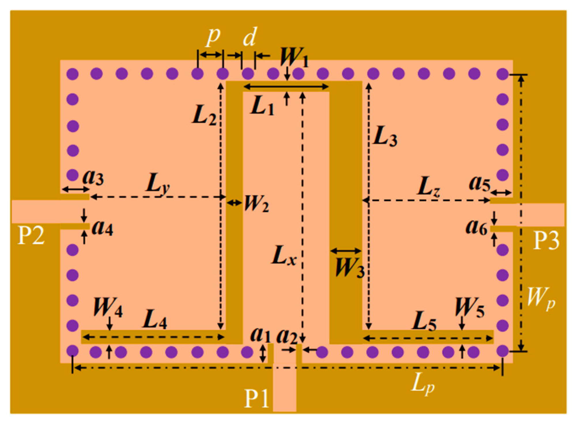
Figure 2.
Development steps of the proposed STA.

Figure 3.
Surface current density by excitation at individual ports: (a) Port 1; (b) Port 2; (c) Port 3.
Figure 3.
Surface current density by excitation at individual ports: (a) Port 1; (b) Port 2; (c) Port 3.

Figure 4.
Equivalent lumped-circuit model of the proposed STA.
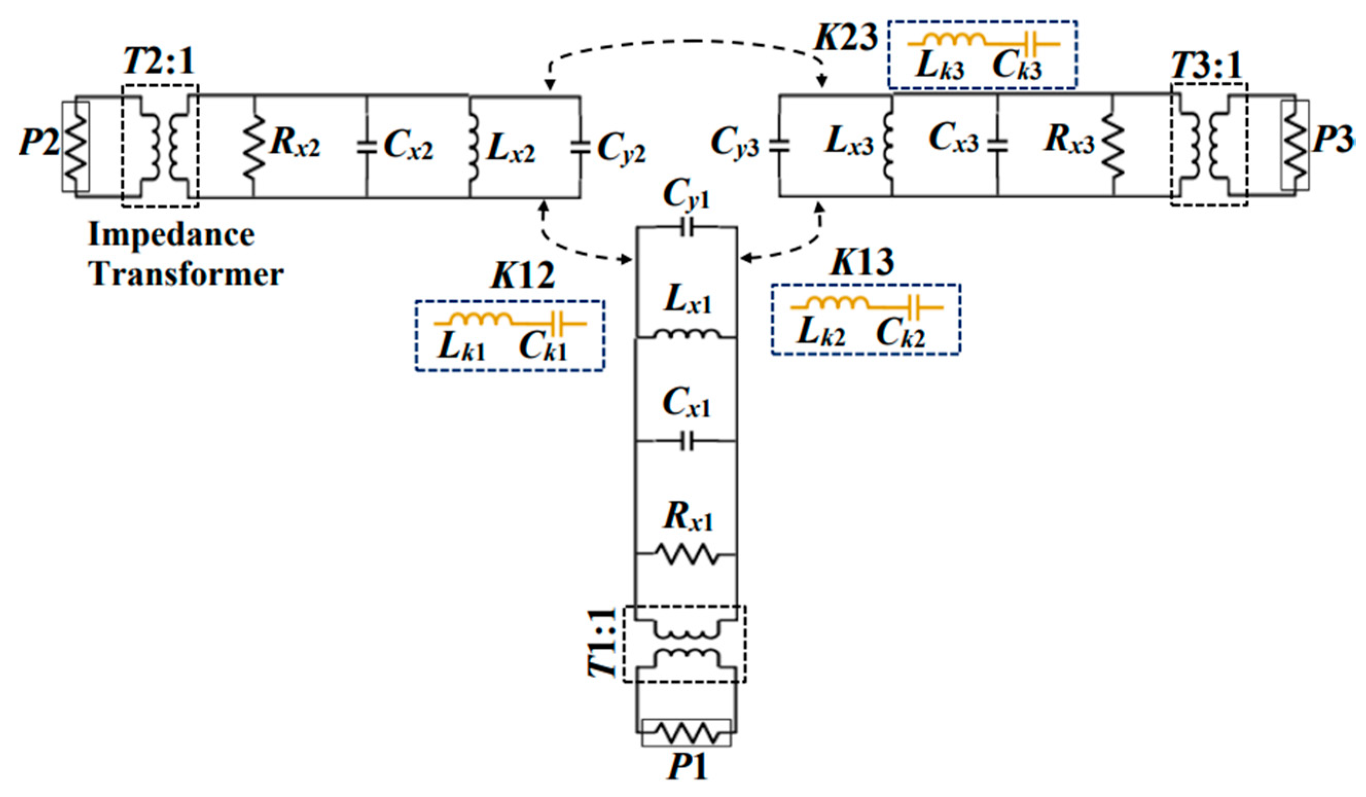
Figure 5.
EM simulation and circuit model simulation of the suggested antenna.

Figure 6.
Independent frequency tunability of the proposed STA: (a) fo1 (port 1); (b) fo2 (port 2); (c) fo3 (port 3).
Figure 6.
Independent frequency tunability of the proposed STA: (a) fo1 (port 1); (b) fo2 (port 2); (c) fo3 (port 3).
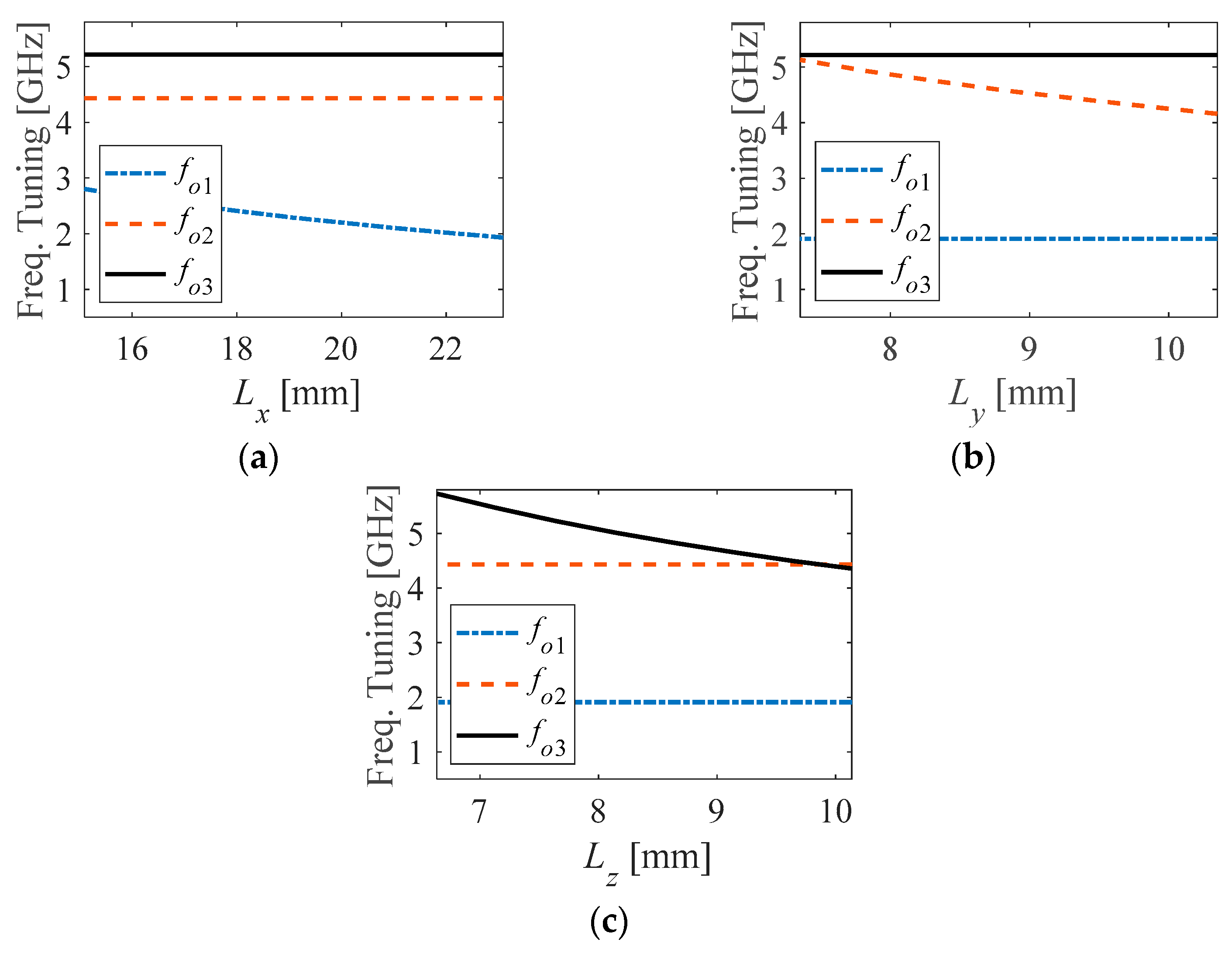
Figure 7.
Fabricated prototype: (a) Front view; (b) Back view.

Figure 8.
Measurement setup for the suggested STA: (a) Reflection coefficients and isolations; (b) Radiation pattern and realized gain.
Figure 8.
Measurement setup for the suggested STA: (a) Reflection coefficients and isolations; (b) Radiation pattern and realized gain.
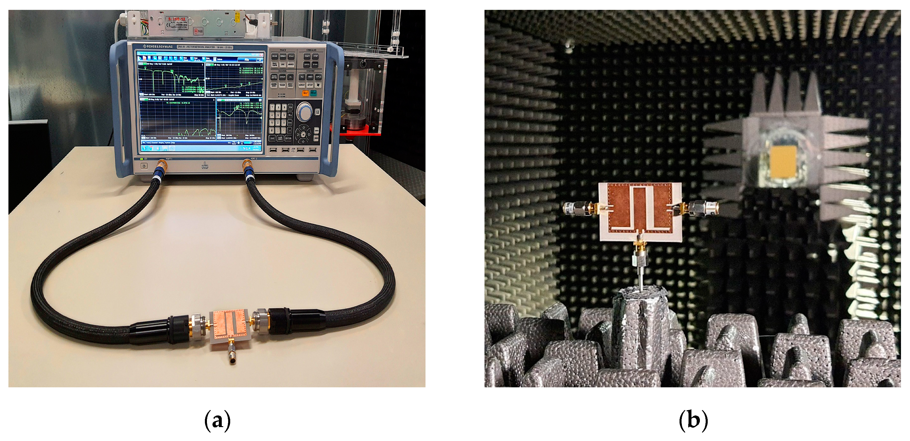
Figure 9.
EM simulation and measurement reflection coefficients of the suggested STA.
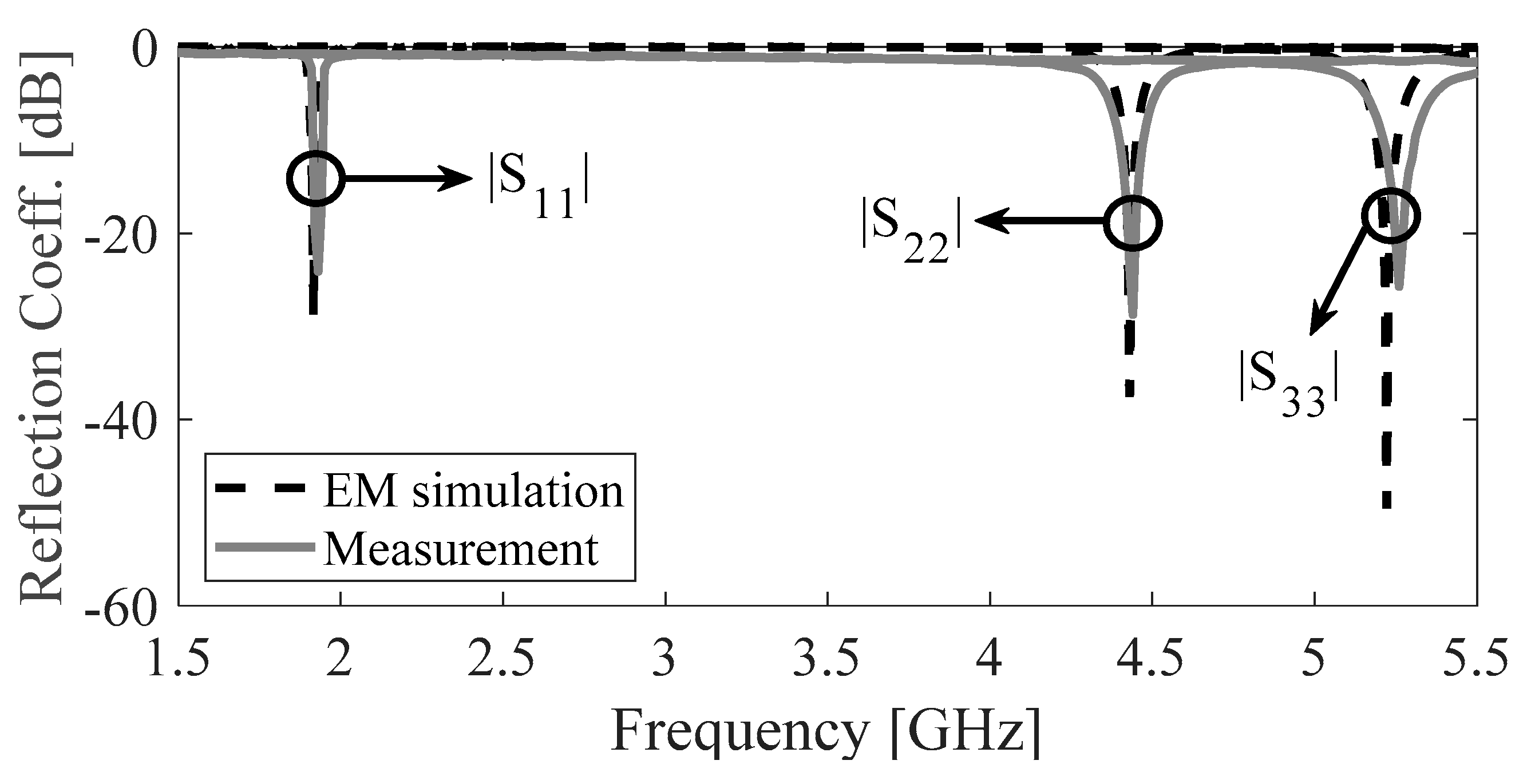
Figure 10.
Port isolation of the proposed STA: (a) EM simulation; (b) measurement.

Figure 11.
EM simulation and measured realized gains of the proposed STA: (a) Port 1; (b) Port 2; (c) Port 3.
Figure 11.
EM simulation and measured realized gains of the proposed STA: (a) Port 1; (b) Port 2; (c) Port 3.

Figure 12.
EM-simulated radiation efficiencies at different port excitation.

Figure 13.
Normalized radiation pattern of the suggested STA associated with (a) port 1, (b) port 2, and (c) port 3. [Simulation—grey, measurement—black); H-plane (left), E-plane (right); copol—solid, crosspol—dashed].
Figure 13.
Normalized radiation pattern of the suggested STA associated with (a) port 1, (b) port 2, and (c) port 3. [Simulation—grey, measurement—black); H-plane (left), E-plane (right); copol—solid, crosspol—dashed].

Table 1.
Lumped-circuit model component values.
| Rx1 (Ω) | Lx1 (nH) | Cx1 (pF) | Cy1 (pF) | Lk1 (nH) | Ck1 (pF) | T1 |
| 239 | 0.373 | 18.6007 | 0.012 | 12.914 | 12.1519 | 0.4597 |
| Rx2 (Ω) | Lx2 (nH) | Cx2 (pF) | Cy2 (pF) | Lk2 (nH) | Ck2 (pF) | T2 |
| 281 | 0.189 | 6.4557 | 0.399 | 7.103 | 10.6529 | 0.429 |
| Rx3 (Ω) | Lx3 (nH) | Cx3 (pF) | Cy3 (pF) | Lk3 (nH) | Ck3 (pF) | T3 |
| 471 | 0.2495 | 1.9587 | 1.7988 | 13.808 | 0.4597 | 0.329 |
Table 2.
Tunable range of the proposed STA and possible application standards.
| Parameter Range | Frequency Range | Application Standards |
|---|---|---|
| 15.09 ≤ Lx ≤ 23.09 (port 1) | 1.93 ≤ f01 ≤ 2.80 | GSM/WiFi/ISM/Bluetooth/LTE/Extended PCS |
| 6.35 ≤ Ly ≤ 10.35 (port 2) | 4.16 ≤ f02 ≤ 5.60 | 5G/WLAN/WiFi/C-band |
| 6.63 ≤ Lz ≤ 10.13 (port 3) | 4.63 ≤ f03 ≤ 5.73 | 5G/WLAN/WiFi/Standard C-band/LTE |
Table 3.
Measured reflection coefficients, isolations, realized gains, and EM-simulated radiation efficiencies.
Table 3.
Measured reflection coefficients, isolations, realized gains, and EM-simulated radiation efficiencies.
| Ports | Freq. (GHz) | Reflection Coeff. (dB) | ISL (dB) | Realized Gain (dBi) | Radiation Efficiency (%) |
|---|---|---|---|---|---|
| 1 | 1.92 | 24.11 | 32.42 | 4.10 | 86.4 |
| 2 | 4.43 | 28.76 | 32.74 | 5.59 | 90.24 |
| 3 | 5.25 | 25.73 | 39.45 | 4.94 | 92.84 |
Table 4.
Performance of the suggested STA and previously reported STAs.
| Ref. | Opertion | Self-Triplexing | Size (λg2) | ISL (dB) | Gain (dBi) | LC Model |
|---|---|---|---|---|---|---|
| [2] | Tri-band | No | 0.195 | NA | 2.1/1.9/5.1 | No |
| [5] | Tri-band | No | 0.462 | >30 | 5.0/6.0/6.5 | No |
| [7] | Tri-band | No | 0.232 | NA | 5.05/4.58/3.17 | No |
| [10] | Tri-band | No | 0.912 | NA | 1.1/0.9/2.1 | No |
| [11] | Tri-band | Yes | 0.28 | >19 | 0.85/4.0/4.23 | No |
| [25] | Tri-band | Yes | 0.42 | >22.5 | 7.2/7.2/7.0 | No |
| [26] | Tri-band | Yes | 0.69 | >26 | 4.5/5.9/6.0 | Yes |
| [27] | Tri-band | Yes | 0.17 | >30.8 | 4.26/4.41/6.27 | No |
| This work | Tri-band | Yes | 0.086 | >32.4 | 4.10/5.59/4.94 | Yes |
ISL: Isolation, λg: Guided wavelength at the lower frequency band, NA: Not available.
Disclaimer/Publisher’s Note: The statements, opinions and data contained in all publications are solely those of the individual author(s) and contributor(s) and not of MDPI and/or the editor(s). MDPI and/or the editor(s) disclaim responsibility for any injury to people or property resulting from any ideas, methods, instructions or products referred to in the content. |
© 2023 by the authors. Licensee MDPI, Basel, Switzerland. This article is an open access article distributed under the terms and conditions of the Creative Commons Attribution (CC BY) license (https://creativecommons.org/licenses/by/4.0/).
Share and Cite
MDPI and ACS Style
Barik, R.K.; Koziel, S. Ultracompact SIRC-Based Self-Triplexing Antenna with High Isolation. Electronics 2023, 12, 2112. https://doi.org/10.3390/electronics12092112
AMA Style
Barik RK, Koziel S. Ultracompact SIRC-Based Self-Triplexing Antenna with High Isolation. Electronics. 2023; 12(9):2112. https://doi.org/10.3390/electronics12092112
Chicago/Turabian StyleBarik, Rusan Kumar, and Slawomir Koziel. 2023. "Ultracompact SIRC-Based Self-Triplexing Antenna with High Isolation" Electronics 12, no. 9: 2112. https://doi.org/10.3390/electronics12092112
Note that from the first issue of 2016, this journal uses article numbers instead of page numbers. See further details here.