

Leakage Current Detector and Warning System Integrated with Electric Meter
by
 , and
, and
Tsung-Hui Cheng
1,
Chien-Hao Chen
1,
Chien-Hung Lin
2,
Bor-Horng Sheu
1,
Chia-Hung Lin
1 and
Wen-Ping Chen
1,* 1
Department of Electrical Engineering, National Kaohsiung University of Science and Technology, No. 415, Jiangong Rd., Kaohsiung City 807618, Taiwan
2
Department of Distribution, Taiwan Power Company, No. 242, Sec. 3, Roosevelt Rd., Taipei City 100208, Taiwan
*
Author to whom correspondence should be addressed.
Electronics 2023, 12(9), 2123; https://doi.org/10.3390/electronics12092123
Submission received: 11 April 2023
/
Revised: 30 April 2023
/
Accepted: 4 May 2023
/
Published: 6 May 2023
(This article belongs to the Topic Applied System on Biomedical Engineering, Healthcare and Sustainability 2023)
Abstract
:Electrical power is essential in human life. Thus, the security and reliability of its supply are of critical importance in a country’s industrial and economic development. The leakage and improper use of electricity may cause serious problems such as fire and electrocution. To prevent such incidents and minimize the loss of life and property, a leakage current detector and warning system are developed in this study. With a high-precision current transformer and high-gain linear converter, the detector effectively detects leakage current over 1 mA, which is validated in different methods. The detector can be integrated into widely used electric meters (Taipower Datong’s sub-meter model D4S) easily, and information on detected leakage current is transmitted to the cloud server through narrowband IoT wireless communication (NB-IoT) to warn users and management personnel of the electrical power line. The proposed detector and system are expected to prevent the fire caused by leakage current which was the main cause of the fire at homes and buildings and can be an effective means to manage the electrical powerline system and metering facilities.
1. Introduction
Electrical power is inevitable in industry and human daily life. However, even with the developed energy storage system, it is impossible to store the supplied power completely. Therefore, power companies need to have a sophisticated power management plan for fluctuating demand and stable supply. Recently, the rapid development of the economy and technology in Taiwan has resulted in a sharp increase in power consumption, especially since the demand for power in the semiconductor industry has increased considerably. The increase in the demand for electrical power and the depletion of the energy supply from closed nuclear power plants urge the development of renewable energy sources and energy storage systems nowadays [1,2]. The reliability of the power supply also needs to be guaranteed [3,4] as it is important to have sustainable manufacturing of various products and related activities in the industry.
In addition to the reliability of the power supply, the safety of using electrical power also must be considered [5,6] as leakage current may cause fires in the building which create the loss of life and property. Many old houses and buildings are vulnerable to leakage current as they do not equip appropriate prevention and warning systems which are not yet popular. Moreover, the installation of such a system often requires the rearrangement of piping, which makes landlords reluctant to have the system due to the inconvenience and high cost.
Among the main causes of fires in Taiwan from 2011 to 2017 (Table 1), reported by the Fire Department of Taiwan’s Ministry of the Interior, leakage current is one of the main causes of fire incidents in Taiwan. Owing to the increase in installing safety equipment, the total number of fires in Taiwan has reduced but electrical failure has remained an important cause of the fire, accounting for 10.6 to 20.0%. The statistics also show that the proportion became higher recently, from 11.2% in 2017 to 20.1% in 2022. This evidences the necessity of the preventive system to prevent leakage current with a detection and warning system as other causes of fire can be prevented through the continuous campaign.
In developing the preventive system of fire, the use of the Internet of Things (IoT) and sensor technology have gained much attention for research [7,8,9]. For example, Chen developed a DIY R-type fire detection system using the Arduino platform in old buildings [10]. Iacovo et al. developed an optical fire detector to cover the area in 120° and 20 m using PbS colloidal quantum dot photodetectors [11]. Faisal et al. designed and evaluated a wireless sensor network to detect abnormal temperature and smoke [12]. Jiang used IoT technology to monitor fires and control fire equipment [13]. Fang et al. applied IoT technology to an evacuation system in the case of fire [14] with existing temperature and smoke sensors. Cloud technology was also used for fire detection by using extracted video features from an IoT device and a cloud server [15]. The fire detection algorithm was developed using a convolutional neural network (CNN) and binary video descriptors. Ankit and Abhishek proposed vision-based surveillance for a privacy-preserving system for fire detection [16] in which an appropriate level of image processing was processed ensuring the privacy of the subjects in images and the accuracy of fire detection.
As most studies on the fire alarm system have focused on detecting fire and equipment malfunction, most proposed systems give out warnings after the incident occurs. Though the systems help to extinguish fires as early as possible, they are not effective at preventing fires. A fire caused by leakage current can be prevented by detecting leakage current caused by overloaded or short circuits. In old buildings, the cable jacket and wire become brittle, and then, the stripped wire can be exposed to moisture or contact with other electrical wires. A narrow conduit or insufficient space for the electrical wires sometimes causes excessive resistance in the wires, which leads to the wire overheating. Old electrical equipment is also susceptible to weakened insulation of the wire. These may cause short circuits which can be detected with leakage current. Therefore, detecting leakage current is useful to prevent fires caused by it. Even though there are several studies on the prevention of such fires [17,18,19], these studies only focus on monitoring the leakage current caused by the damaged wire insulator. Thus, more studies are required in monitoring leakage current to prevent corresponding fires.
The advancement of sensor technology and machine learning technology allows the prediction of any incident caused by leakage current. Recently, Morshed et al. used a mixed model of multi-class support vector machines (MSVM) to monitor the historical data of normal and leakage currents in household electrical equipment to determine the leakage current [20]. The data were stored in a structured database that could be accessed remotely via the Internet. The effectiveness of the proposed system was validated by the results, which can be used to prevent fire by monitoring and detecting leakage current for electrical safety. To further develop the system for the effective prevention of fire caused by the leakage current from the deterioration or improper use of electrical appliances, an advanced leakage current detection device is proposed in this study based on the Taipower Datong model D4S which is mainly used in Taiwan. With a high-precision current transformer (CT), and using a cloud monitoring and reporting system, the device effectively detects and transmits the leakage current signal to a cloud server for real-time recording. Then, the abnormality of the leakage current is monitored and used to send warnings to electricians for appropriate actions. Therefore, the proposed user-side leakage current detector helps to establish regulatory and inspection measures and assist users in preventing fires.
2. Development of Device
This study involves monitoring the aging condition of electrical wires using a leakage current detection device. When the leakage current becomes excessive, it indicates that the insulating sheath of the wire has severely deteriorated, necessitating an update of the internal wiring to prevent potential fire incidents caused by the persistent excessive leakage current, which may lead to the ignition of the electrical wires. A detailed description of the leakage current detection device and real-time notification system research is as follows:
2.1. Device Structure
Figure 1 shows the system structure of the proposed device. The device has different parts for leakage current detection, wireless communication, and 3D modeling of the house. A detailed description of each part is as follows (Figure 2).
- (1)
- Leakage current detection circuit
When the insulating outer layer of electrical wires deteriorates due to aging, resulting in leakage current, the initial current value of the leakage current is only at the microampere (uA) level. The research requires high magnetic conductivity and high turns ratio current transformers, as well as instrumentation amplifiers. The leakage current detection is conducted by a high-precision current transformer (Figure 3) that has a turns ratio of 1:2000, a winding resistance of 43 Ω, a load resistance of 200 Ω, and a total resistance of 35.3 Ω. Figure 2 shows the V-I characteristic of the CT. Since the CT performs non-contact measurements, there is no need to modify the existing power lines, and the current measurement process does not include circuit signal transmission to prevent any interference from the magnetic field of the CT coil.
After the signal is amplified by a high-rate linear converter as shown in Figure 4, an analog-to-digital converter (ADC) samples the signal on a microcontroller (MCU). The impedance of the instrumentation amplifier is calculated as Equation (1).
where G is the amplification ratio and RG is the external impedance. Changing the external impedance adjusts the amplification ratio. The analog current signal sensed by the CT is converted to a digital signal by the MCU by linear sampling. Since the analog current signal of the user-side leakage current detected by the CT is not strong, the characteristic of a differential amplifier with strong common-mode rejection capability is used to amplify the analog current signal. The differential amplifier is specially designed with two input terminals to amplify only the differential signal and automatically reject the common mode signal. Its features include low DC bias, low drift, low noise, high open-loop gain, and a common-mode rejection ratio. Its transfer function is given by Equation (2).
where is the output voltage, and are the input voltages, and and are matching impedances. The instrumentation amplifier is an enhanced version of the differential amplifier that has the advantage of the voltage-follower amplifier on input terminals. These voltage follower amplifiers have a high input impedance, eliminating the need for input impedance matching and considering the load effect on gain. The equation applied for the instrumentation amplifier is as follows.
where is the output voltage, and are the input voltages, is the fixed impedance, and is the matching impedance.
- (2)
- Wireless transmission communication
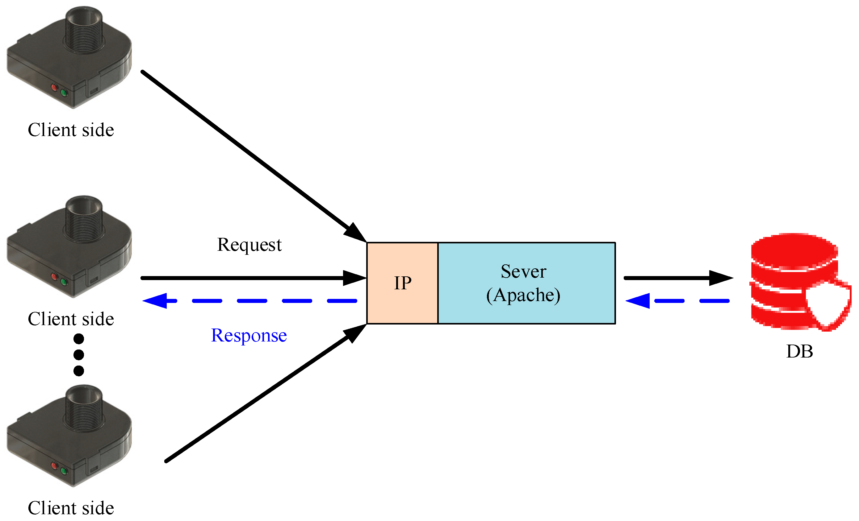
Narrowband IoT (NB-IoT) is one of the most common low-power digital transmission technologies in IoT applications. It was developed by the 3GPP organization to use GSM and LTE (900 MHz) bands by telecommunications companies. Authorization to use the associated services must be obtained by purchasing the license from a telecommunication operator or third-party agent. NB-IoT does not need to rebuild the network, which is one of the advantages. Only software updates are required to use the existing 4G network and equipment. In addition, by using a telecom-grade network, NB-IoT provides a high level of assurance of communication quality and message security. In this study, we used the universal asynchronous receiver/transmitter (UART) on the main control unit (MCU) to control the timed sleep and wake-up mode of the NB-IoT module. The proposed device (user-side) accesses the server to transmit data as shown in Figure 5. The data transfer format is JSON to save network traffic.
- (3)
- 3D modeling of the case
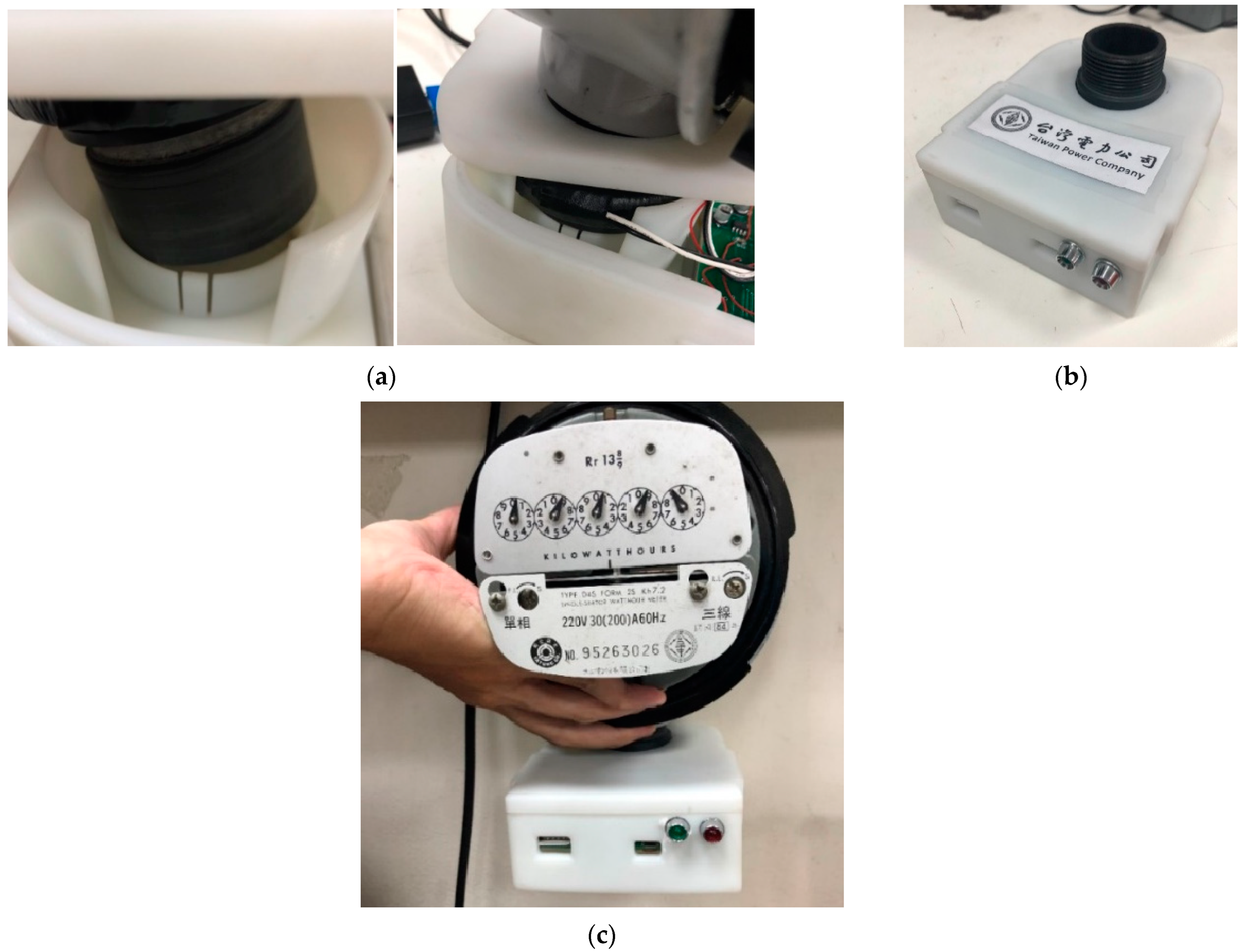
The leakage current detector device in this study was designed using Fusion 360 3D modeling software as shown in Figure 2a. Its dimensions were 66 mm (outer diameter), 45 mm (inner diameter), and 10 mm (height). The size of the lithium battery included in the device was 50 × 30 × 10 mm (length × width × height). The DN32 specification was used in the device to directly connect it to the electric meter. For the connection, an adjustable clip (a bearing-like mechanism) was used to fix the device easily to the wire pipe.
- (4)
- NB-IoT protocol
The leakage current detected by the device was transmitted to the cloud server via NB-IoT wireless communication. The transmittance workflow is shown in Figure 6. In using NB-IoT, an initialization configuration was required to establish a connection between the client (device) and the server. The connection is confirmed before sending and receiving data to ensure the quality of communication. The NB-IoT communication adopts the HTTP transmission protocol in the JSON format. With this method, leakage current is monitored by electricians using their mobile devices.
2.2. Real-Time Data Management
Two different types of leakage current are detected by the device: isolated leakage current and overcurrent. Leakage current is determined when the current through the electrical wire exceeds the safe current range which is 1 mA. When leakage current is detected, the information is transmitted to the server via HTTP communication protocol and is further forwarded to the mobile device or back-end management system of electricians. Figure 7 shows the architecture of the monitoring system, which is built on the Microsoft SQL Server with 2019 database software and Internet Information Services (IIS). When the server receives information on leakage current from the developed device, the server notifies the back-end administrator and pushes a real-time notification to the mobile device of the electrician for troubleshooting. The data transfer system is described in Figure 8.
3. Test Result and Discussion
3.1. Installation of Device with Electric Meter
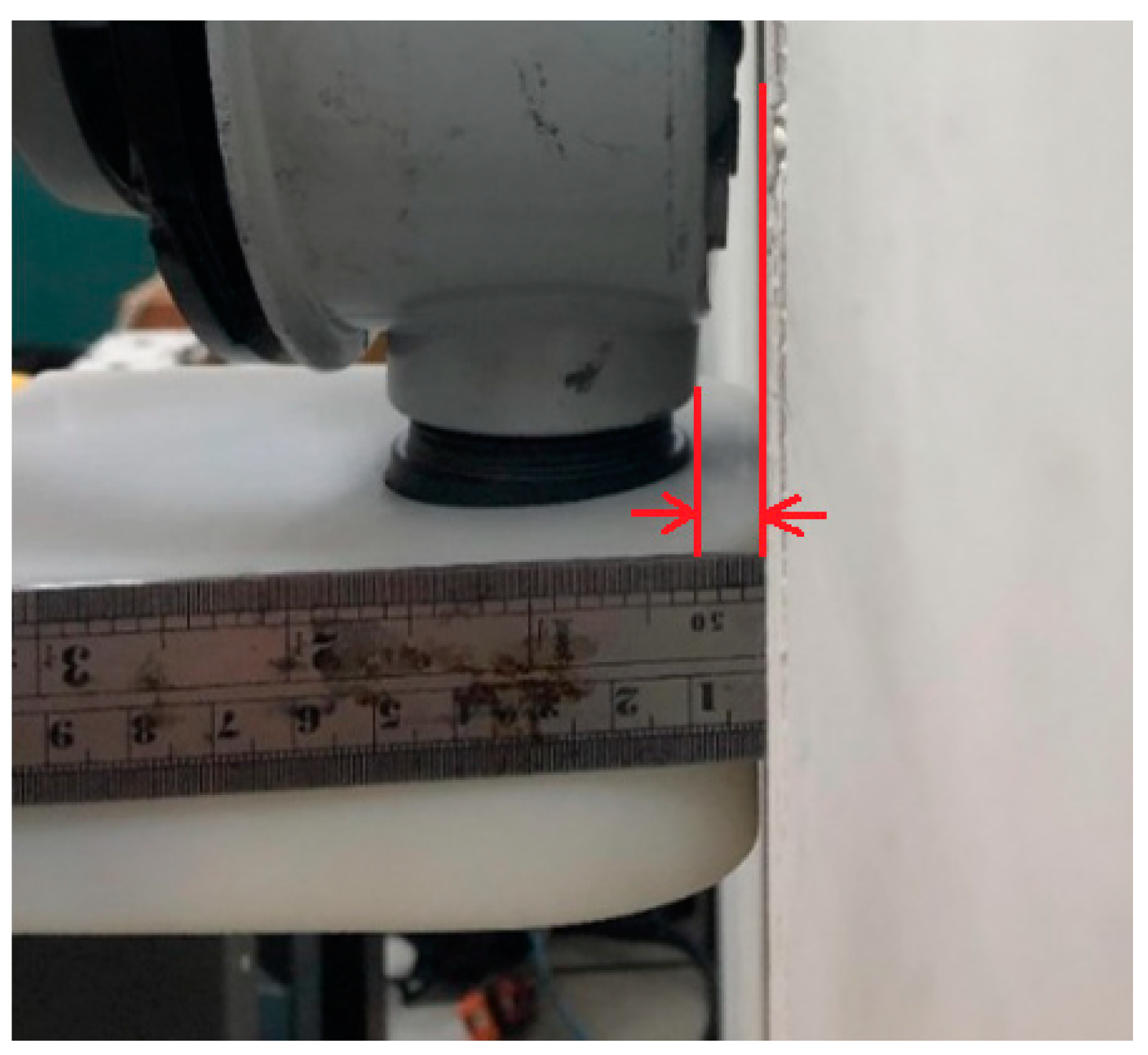
Figure 9 shows the installation of the Taipower Datong model D4S. The space between the electric meter and the wall is about 5 mm. Therefore, the leakage current detector must be implemented beneath the electric meter within 5 mm. The component and the manufacturing and installation of the device are described as follows.
3.2. Manufacturing Components of Device
- (1)
- Leakage current detection circuit and high gain linear converter
The CT used in the device is shown in Figure 10a. Its V-I characteristic is presented in Figure 10b. Figure 11 depicts the circuit of the high-precision current transformer (CT) with a high-gain linear converter which amplifies the leakage current from around 0.5 μA to 1 mA.
- (2)
- Assembly of the leakage current detector
The coil of the CT in the leakage current detector is mounted as shown in Figure 12.
3.3. Monitoring Software
In this study, an Android-based mobile application was developed to monitor leakage current detection status. When a leakage current occurs, the app immediately notifies the user and electricians through an alarm function. With leakage current, the app displays ‘error’ on the status window, or it shows ‘normal’ or ‘test’ (Figure 14).
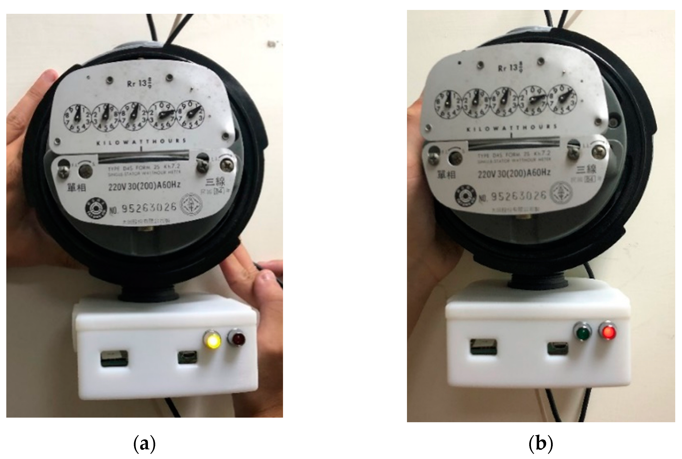
The app can be used with a subscriber identification module (SIM) card to connect to the NB-IoT module for data transmission. The MCU sends AT commands to the NB-IoT module to establish a client connection to the host. After the connection is established, the device uses the HTTP protocol to upload data in JSON format. The wireless network notifies the mobile APP interface. The detector has external lights to show the normal condition with a green LED light when the detected leakage current is less than 1 mA, while the abnormal condition is indicated with a red LED light for leakage current over 1 mA (Figure 15).
3.4. Testing Leakage Current Detector
In the test, two sets of 110 Vac were used to simulate the leakage current and test the functionality of the leakage current detector. The test method is described in Figure 16, where one set of 110 Vac circuitry was passed through the device end to simulate the current load. Since both lines of the circuit passed through the device, the total current sum always must be zero regardless of the current load. The other set of circuitry passed through only one line through the device end to simulate the generation of leakage current, and the current was controlled by a resistor. The leakage current was judged by two verification methods: measuring the voltage on the secondary side of the CT with an oscilloscope (method 1) and measuring the current with a digital multimeter (method 2).
Method 1 is to calculate the theoretical value of the leakage current through Ohm’s theorem, while test method 2 is to use the secondary side of the current transformer (CT) to calculate the leakage current and compare the theoretical and actual measurement values to check the leakage current of the two verification methods difference to verify the correctness of the CT circuit. It can be seen from the two verification methods that the leakage current difference is very close, and finally connect the device to the serial monitoring test software to display the current leakage current value, as shown in Figure 14, the value is 783 µA, and the current state was determined to be normal to verify the accuracy of the test results. In the experiment, the turns ratio of the CT coil was 1:2000, and the matching impedance was 10 KΩ. Two different simulated load circuits were selected for testing normal and leakage currents.
The test circuit for the device was powered by a single-phase three-wire 220 V system. The red and black wires are for the live and neutral wires, respectively. All the wires passed through the detector to measure the leakage current in the single-phase three-wire circuit which was generated in the two circuits (Figure 17). One circuit passes only one wire through the CT coil, while the other wire is placed outside the coil to create a simulated leakage current. Two different wirings were used to test the device. In the first set to simulate the normal condition, the live (L) and neutral (N) wires of the load circuit pass through the CT coil, and the measured leakage current value is less than 1 mA (Figure 17a). When the CT coil passes through the N or L wire only, and the measured leakage current value is greater than 1 mA in the second set to simulate the abnormal condition (Figure 17b).
- (a)
- Normal condition
Table 2 and Table 3 show the result of testing the detector at the normal condition using two different methods. The first method was to measure the voltage and leakage current, while the second method was to use the secondary voltage, and the turns ratio and impedance of the CT to calculate the leakage current. The leakage current obtained with the two methods is close with a difference of around 5%. When the device was connected to monitoring test software, the leakage current was 783 μA. Thus, test set 1 was judged to be normal and was used to verify the accuracy of the test results.
- (b)
- Abnormal condition
The leakage current is close with a difference of around 4.7%. The monitoring software displayed the leakage currents (Figure 18).
In the case of leakage current, to prevent unauthorized operation or accidental contact with the detector, the power switch of the CT is located inside the detector. To switch on the lithium battery charge and discharge protection module (IP5306) to activate the power supply circuit, the case must be opened first, which only can be performed by an authorized electrician (Figure 19).
4. Conclusions
Due to the improper use of electricity and the aging of electrical wires, the resulting leakage current is a major cause of fires. Thus, it is necessary to detect and monitor leakage current in advance to prevent fires. In addition, an early warning system based on the detection of leakage current is also required for electricians to maintain and troubleshoot the problems that may cause leakage current and fires. Therefore, we developed a leakage current detector and warning system using a CT, a high-gain linear converter, and low-power NB-IoT wireless communication technology. This system monitors leakage current in real time in a user’s unidirectional three-wire system and its monitoring software can run on Android 10.0 (Q) for the efficient management of the electrical wire. The device can be easily integrated with the present electric meter that is mostly used at home. The test result of the device and the system showed that a leakage current over 1 mA was detected successfully, and the system efficiently gives out a warning for leakage current through the NB-IoT and by indicating lights installed out of the detector. To prevent unexpected operation, the detector was designed to be operated only by authorized personnel. The proposed detector and system are expected to be integrated with the metering system of the electrical power company for better management of the power supply system and the effective prevention of leakage current and unexpected fire caused by it. This study can evaluate the integration of leakage current detectors and warning systems within task automation systems (TASs).
Author Contributions
Conceptualization, C.-H.L. (Chien-Hung Lin); Validation, C.-H.C.; Investigation, C.-H.L. (Chia-Hung Lin); Writing—original draft, T.-H.C.; Writing—review & editing, B.-H.S.; Supervision, W.-P.C. All authors have read and agreed to the published version of the manuscript.
Funding
This study was supported by the Ministry of Science and Technology (MOST) of Taiwan and Taiwan Power Company under the project MOST 110-2622-E-992-006 and 07710000401.
Data Availability Statement
Data is contained within the article shown as Figure 11b.
Conflicts of Interest
The authors declare no conflict of interest.
References
- Chung, Y.-L. Energy-Saving Transmission for Green Macrocell–Small Cell Systems: A System-Level Perspective. IEEE Syst. J. 2017, 11, 706–716. [Google Scholar] [CrossRef]
- Wang, C.-N.; Nguyen, N.-A.-T.; Dang, T.-T.; Bayer, J. A Two-Stage Multiple Criteria Decision Making for Site Selection of Solar Photovoltaic (PV) Power Plant: A Case Study in Taiwan. IEEE Access 2021, 9, 75509–75525. [Google Scholar] [CrossRef]
- Mulvaney, D. Solar’s green dilemma. IEEE Spectr. 2014, 51, 30–33. [Google Scholar] [CrossRef]
- Liu, K.-H.; Lin, P. Toward self-sustainable cooperative relays: State of the art and the future. IEEE Commun. Mag. 2015, 53, 56–62. [Google Scholar] [CrossRef]
- Martínez, J.; Gómez-Pau, A.; Riba, J.-R.; Moreno-Eguilaz, M. On-Line Health Condition Monitoring of Power Connectors Focused on Predictive Maintenancem. IEEE Trans. Power Deliv. 2021, 36, 3611–3618. [Google Scholar] [CrossRef]
- Milić, S.D.; Babić, B.M. Toward the Future—Upgrading Existing Remote Monitoring Concepts to IIoT Concepts. IEEE Internet Things J. 2020, 7, 11693–11700. [Google Scholar] [CrossRef]
- Hajovsky, R.; Pies, M.; Velicka, J.; Slany, V.; Rous, R.; Danys, L.; Martinek, R. Design of an IoT-Based Monitoring System as a Part of Prevention of Thermal Events in Mining and Landfill Waste Disposal Sites: A Pilot Case Study. IEEE Trans. Instrum. Meas. 2023, 72, 5500114–5500127. [Google Scholar] [CrossRef]
- Arya, A.K.; Kim, S.; Ko, K.; Kim, S. Antenna for IoT-Based Future Advanced (5G) Railway Communication with End-Fire Radiation. IEEE Internet Things J. 2022, 9, 7036–7042. [Google Scholar] [CrossRef]
- Sendra, S.; García, L.; Lloret, J.; Bosch, I.; Vega-Rodríguez, R. LoRaWAN Network for Fire Monitoring in Rural Environments. Electronics 2020, 9, 531. [Google Scholar] [CrossRef]
- Chen, S.-S.; Wang, L.K.; Li, W.-H.; Chen, W.-P. A low-cost R-type fire alarm system for old houses. In Proceedings of the 2016 International Conference on Advanced Materials for Science and Engineering (ICAMSE), Tainan, Taiwan, 5–10 November 2016; pp. 51–54. [Google Scholar]
- De Iacovo, A.; Venettacci, C.; Colace, L.; Scopa, L.; Foglia, S. PbS Colloidal Quantum Dot Visible-Blind Photodetector for Early Indoor Fire Detection. IEEE Sens. J. 2017, 17, 4454–4459. [Google Scholar] [CrossRef]
- Saeed, F.; Paul, A.; Rehman, A.; Hong, W.H.; Seo, H. IoT-Based Intelligent Modeling of Smart Home Environment for Fire Prevention and Safety. J. Sens. Actuator Netw. 2018, 7, 11. [Google Scholar] [CrossRef]
- Jiang, H. Mobile Fire Evacuation System for Large Public Buildings Based on Artificial Intelligence and IoT. IEEE Access 2019, 7, 64101–64109. [Google Scholar] [CrossRef]
- Fang, H.; Lo, S.; Lo, J.T.Y. Building Fire Evacuation: An IoT-Aided Perspective in the5G Era. Building 2021, 11, 643. [Google Scholar] [CrossRef]
- Altowaijri, A.H.; Alfaifi, M.S.; Alshawi, T.A.; Ibrahim, A.B.; Alshebeili, S.A. A Privacy-Preserving Iot-Based Fire Detector. IEEE Access 2021, 9, 51393–51402. [Google Scholar] [CrossRef]
- Jain, A.; Srivastava, A. Privacy-Preserving Efficient Fire Detection System for Indoor Surveillance. IEEE Trans. Ind. Inform. 2022, 18, 3043–3054. [Google Scholar] [CrossRef]
- Wong, K.L.; Pathak, S.; Yu, X. Aging effect on leakage current flow in wooden poles. IEEE Trans. Dielectr. Electr. Insul. 2009, 16, 133–138. [Google Scholar] [CrossRef]
- Wong, K.L.; Rahmat, M.F. Study of Leakage Current Distribution in Wooden Pole Using Ladder Network Model. IEEE Trans. Power Deliv. 2010, 25, 995–1000. [Google Scholar] [CrossRef]
- Wong, K.L.; Rahmat, M.F. Feasibility Study of Leakage Current Shunting Method Based on the Ladder Network Model. IEEE Trans. Power Deliv. 2010, 25, 1133–1137. [Google Scholar] [CrossRef]
- Alam, M.M.; Shahjalal, M.; Rahman, M.H.; Nurcahyanto, H.; Prihatno, A.T.; Kim, Y.; Jang, Y.M. An energy and leakage current monitoring system for abnormality detection in electrical appliances. Sci. Rep. 2022, 12, 18520. [Google Scholar] [CrossRef] [PubMed]
Figure 1.
System structure of the leakage current detector.

Figure 2.
Leakage current detector developed in this study. (a) Design of device; (b) parts of device.
Figure 2.
Leakage current detector developed in this study. (a) Design of device; (b) parts of device.

Figure 3.
V-I characteristics of a high-accuracy current transformer.

Figure 4.
A high-rate linear converter.

Figure 5.
Architecture of wireless communication NB-IoT.

Figure 6.
NB-IoT communication flow.

Figure 7.
Architecture of data management of the real-time monitoring system of the leakage current detector.
Figure 7.
Architecture of data management of the real-time monitoring system of the leakage current detector.

Figure 8.
Data transfer process of the leakage current detector.

Figure 9.
Installation of an electric meter (D4S). The space between the meter and the wall is about 5 mm.
Figure 9.
Installation of an electric meter (D4S). The space between the meter and the wall is about 5 mm.

Figure 10.
Picture of high-precision current transformer (CT) and its V-curve. (a) Assembled CT; (b) V-I characteristic curve of CT.
Figure 10.
Picture of high-precision current transformer (CT) and its V-curve. (a) Assembled CT; (b) V-I characteristic curve of CT.

Figure 11.
Circuit of the leakage current detector and high gain converter, and the circuit’s I-I; (a) Circuit of the leakage current device (the high-gain linear converter is in a red box.); (b) I-I characteristic curves of the circuit.
Figure 11.
Circuit of the leakage current detector and high gain converter, and the circuit’s I-I; (a) Circuit of the leakage current device (the high-gain linear converter is in a red box.); (b) I-I characteristic curves of the circuit.

Figure 12.
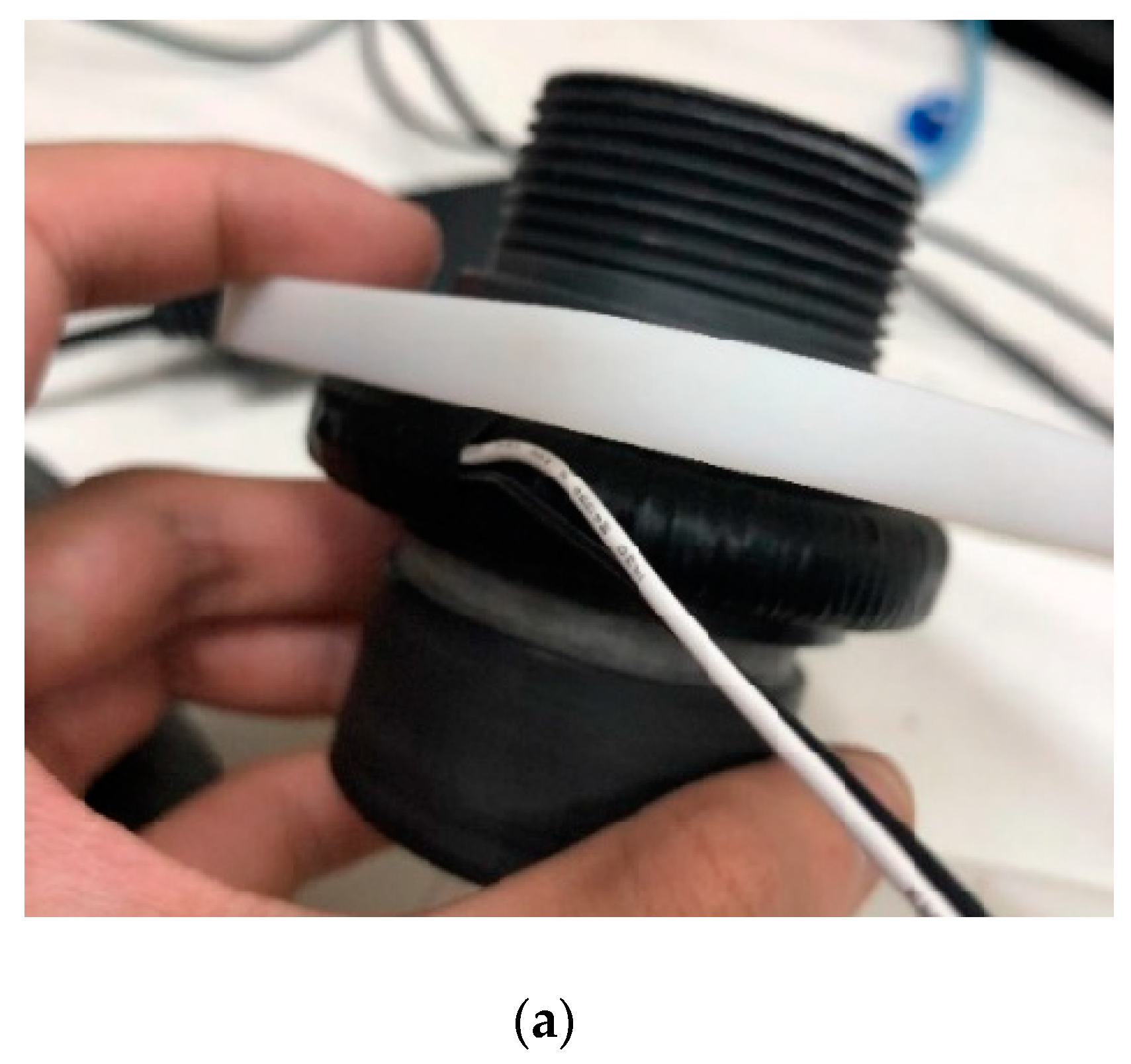
CT coil attached to the electric meter (D4S). (a) CT mounted on the leakage current detector; (b) front view of the CT coil attached to the electric meter; (c) side view of the installation of the CT coil.
Figure 12.
CT coil attached to the electric meter (D4S). (a) CT mounted on the leakage current detector; (b) front view of the CT coil attached to the electric meter; (c) side view of the installation of the CT coil.


Figure 13.
Assembly of the leakage current detector. (a) Inserting the CT coil into the detector; (b) assembled CT coil and the detector; (c) completed installation of the leakage current detector in the electric meter.
Figure 13.
Assembly of the leakage current detector. (a) Inserting the CT coil into the detector; (b) assembled CT coil and the detector; (c) completed installation of the leakage current detector in the electric meter.

Figure 14.
Monitoring software for the leakage current detector.

Figure 15.
Lights indicating leakage current. (a) Green LED light indicating normal condition; (b) red LED light indicating abnormal condition.
Figure 15.
Lights indicating leakage current. (a) Green LED light indicating normal condition; (b) red LED light indicating abnormal condition.

Figure 16.
Simulation method of load and leakage current.

Figure 17.
Schematic diagram of the leakage current test. (a) Test set 1; (b) Test set 2.

Figure 18.
Screenshot of the test results in the monitoring software for abnormal condition.

Figure 19.
Discharge protection module (IP5306) and the switch (in a yellow circle) of the leakage current detector circuit.
Figure 19.
Discharge protection module (IP5306) and the switch (in a yellow circle) of the leakage current detector circuit.


Table 1.
Statistics on the total number of fires and the main causes of fires in Taiwan from 2017 to 2022.
Table 1.
Statistics on the total number of fires and the main causes of fires in Taiwan from 2017 to 2022.
| Year | Heating Devices | Stove Cooking | Leakage Current | Cigarette Butts | Total |
|---|---|---|---|---|---|
| 2017 | 5810 | 3659 | 3433 | 1461 | 30,464 |
| 2018 | 6353 | 3591 | 2971 | 1530 | 27,922 |
| 2019 | 3880 | 3113 | 3042 | 1832 | 22,866 |
| 2020 | 3305 | 2593 | 2873 | 1437 | 22,248 |
| 2021 | 2694 | 1754 | 2905 | 1649 | 21,684 |
| 2022 | 2036 | 1496 | 2890 | 1483 | 14,396 |
Table 2.
Test parameters for test set 1 (normal condition).
| Method 1 | Method 2 | ||||
|---|---|---|---|---|---|
| Ohm’s Law (Theoretical Value) | CT Secondary Side Calculates Its Leakage Current Value (Measured Value) | ||||
| Main Voltage | Leakage Current Load | Oscilloscope Measurement of Secondary Voltage of CT (Vrms) | Turns Ratio of CT | Impedance of the Secondary Voltage of CT | |
| Measured value | 121.6 Vac | 149.4 kΩ | 3.906 mV | 1:2000 | 10 kΩ |
| Leakage current | 813.9 uA | 781.2 uA | |||
| Difference | 4.17% | ||||
Table 3.
Test parameters for test set 2 (abnormal condition).
| Method 1 | Method 2 | ||||
|---|---|---|---|---|---|
| Ohm’s Law (Theoretical Value) | CT Secondary Side Calculates Its Leakage Current Value (Measured Value) | ||||
| Main Voltage | Leakage Current Load | Oscilloscope Measurement of Secondary Voltage of CT (Vrms) | Turns Ratio of CT | Impedance of the Secondary Voltage of CT | |
| Measured value | 121.6 Vac | 98.8 kΩ | 5.866 mV | 1:2000 | 10 kΩ |
| Leakage current | 1230.7 μA | 1173.2 μA | |||
| Difference | 4.9% | ||||
Disclaimer/Publisher’s Note: The statements, opinions and data contained in all publications are solely those of the individual author(s) and contributor(s) and not of MDPI and/or the editor(s). MDPI and/or the editor(s) disclaim responsibility for any injury to people or property resulting from any ideas, methods, instructions or products referred to in the content. |
© 2023 by the authors. Licensee MDPI, Basel, Switzerland. This article is an open access article distributed under the terms and conditions of the Creative Commons Attribution (CC BY) license (https://creativecommons.org/licenses/by/4.0/).
Share and Cite
MDPI and ACS Style
Cheng, T.-H.; Chen, C.-H.; Lin, C.-H.; Sheu, B.-H.; Lin, C.-H.; Chen, W.-P. Leakage Current Detector and Warning System Integrated with Electric Meter. Electronics 2023, 12, 2123. https://doi.org/10.3390/electronics12092123
AMA Style
Cheng T-H, Chen C-H, Lin C-H, Sheu B-H, Lin C-H, Chen W-P. Leakage Current Detector and Warning System Integrated with Electric Meter. Electronics. 2023; 12(9):2123. https://doi.org/10.3390/electronics12092123
Chicago/Turabian StyleCheng, Tsung-Hui, Chien-Hao Chen, Chien-Hung Lin, Bor-Horng Sheu, Chia-Hung Lin, and Wen-Ping Chen. 2023. "Leakage Current Detector and Warning System Integrated with Electric Meter" Electronics 12, no. 9: 2123. https://doi.org/10.3390/electronics12092123
Note that from the first issue of 2016, this journal uses article numbers instead of page numbers. See further details here.