
Wide-Angle Beam-Switching Antenna with Stable Gain Based on a Virtual Image Lens

1
Division of Electromagnetic Engineering and Fusion Science, KTH Royal Institute of Technology, SE-100 44 Stockholm, Sweden
2
Antenna and Sub-Millimetre Waves Section, European Space Agency, 2200 AG Noordwijk, The Netherlands
*
Author to whom correspondence should be addressed.
Electronics 2024, 13(6), 1034; https://doi.org/10.3390/electronics13061034
Submission received: 29 December 2023
/
Revised: 4 March 2024
/
Accepted: 7 March 2024
/
Published: 10 March 2024
(This article belongs to the Special Issue Advanced Antenna Technologies for B5G and 6G Applications)
Abstract
:Beam-switching antennas based on quasi-optical beamformers can provide cost-effective solutions for high-frequency communication applications. Here, we propose a wide-angle beam-switching planar lens antenna based on the recently presented virtual image lens. The antenna operates from 24 to 28 GHz and produces a beam that can be steered in a 100-degrees range in one plane with less than 2 dB simulated gain variation over the angular range and operational band. The performance of the presented antenna is similar to reported lens antennas with stable gain, but the proposed lens requires a smaller refractive index range to be realized, which alleviates the manufacturing.
1. Introduction
Mobile terrestrial network systems, including and beyond the fifth generation (5G), are expected to operate at higher frequencies than their predecessors to support higher data rates [1]. For instance, frequency range 2 (FR2) of the 5G spectrum covers frequencies from 24.25 GHz to 52.6 GHz [2]. Base station antennas for these high-frequency systems are required to provide wide-angle beam steering capabilities to ensure a high quality of service (QoS) to end users within the service area of the antenna. The antenna may also be operated using multiple simultaneous beams, dividing the field of view into sectors enabling more than one user at a time. In the current communication systems, beam steering is often obtained using array antennas, however, at frequencies in FR2, the feeding networks of the array antennas can be prohibitively costly and lossy, even more so in the case of multiple simultaneous beams.
Parallel plate waveguide (PPW) quasi-optical beamformers provide attractive properties for antenna systems at high frequencies (typically above 20 GHz) [3,4,5,6,7,8,9,10,11,12,13,14]. Importantly, these beamformers can enable beam steering over a wide field of view without costly and lossy circuitry, which makes them attractive for future communication systems. Specifically, non-rotationally symmetric quasi-optical beamforming antennas have demonstrated beam steering up to [3,4,5,6,7,8]. A wider steering range can be obtained using antennas based on rotationally symmetric lenses, e.g., Luneburg lenses [9,10,11,12,13,14].
These antennas typically achieve beam steering by switching between several feeds placed along the focal curve of the beamformer. This technique allows for a simple and cost-effective beam steering. However, the beams are directed at fixed angles, and as a result, the QoS to users located between two beam maxima may degrade significantly. The reduction in gain for these users depends on the angular separation between the beams and their directivity and can be as large as 10 dB with respect to the peak gain [14], resulting in important power flux density (PFD) variations across the service area. The angular resolution between the beams is determined by the smallest feed separation, which typically must be larger than half-a-wavelength for the common rectangular waveguide feeds. The same limitation occurs in the case of multiple simultaneous fixed beam systems, as the antenna solution is typically the same, while the centralized communication module together with the switching network are replaced with multiple communication modules (generally one per antenna feed).
In [15], the authors overcome the low gain between beams in a reflector-based PPW antenna by interleaving two vertically stacked feed arrays placed along the focal arc of the reflector. This allows for a stable gain in a wide field of view but the closely spaced beams produced by the same aperture have high correlation, which leads to reduced directivity and increased side lobe levels [16,17]. The issues stemming from the beam correlation can be overcome by using two apertures, as proposed in [18,19], but the resulting antenna is bulky. The low gain between beams in rotationally symmetric lens antennas can be overcome by displacing the focal arc from the beamformer [20]. However, as also observed in the reflector-based antennas, closely spaced beams that share an aperture can suffer from performance degradation due to the beam correlation, which limits the obtainable gain stability. Alternatively, the lens can be modified to produce a non-collimated beam [21,22], thus increasing the beam width. With this approach, the gain in the antenna can be arbitrarily stable when scanning, but the directivity is inherently reduced compared to the antenna with a perfectly collimating lens. This may be compensated by increasing the signal amplification levels in the transmit/receive modules connected to the antenna, resulting in equivalent PFD compared to collimating systems and thus enhanced QoS over the complete field of view thanks to the reduced angular dependency. It is worth noting that the range of refractive indices to be implemented in [21] is similar to the perfectly collimating Luneburg lens [23]. On the other hand, in [22], the range of refractive indices to be implemented is significantly larger than that of the Luneburg lens, which may introduce challenges in the realization of the lens.
Here, we present a lens antenna with stable gain in the beam-steering plane. The antenna is based on a recently proposed rotationally symmetric gradient index lens that produces a non-collimated beam [24]. This lens is referred to as a virtual image lens and can be used to produce a lens antenna with a wide beam. The lens is fed at its border with 11 rectangular waveguides and produces beams that can be switched in a range with a simulated gain that varies less than 2 dB in the steering plane from 24 to 28 GHz. This frequency range corresponds to the 5G n258 band intended for millimetre-wave cells [25]. The gain variation when scanning is smallest at the lower part of the band, where the gain is within 1 dB throughout the scanning range. It is important to note that the refractive index range required to realize the lens is low compared to the lenses in [21,22]. Furthermore, conversely to [21], the lens used in the antenna can be directly derived using analytical formulas [24] and does not require optimization to be obtained.
The paper is organized as follows. Section 2 presents the virtual image lens and how it can be integrated into an antenna capable of switching its radiation in a wide angular range. The implementation of the gradient index medium and its realization using additive manufacturing is also discussed. Section 3 presents the simulated and measured reflection and radiation properties of the antenna. In Section 4, the performance of the antenna is discussed in relation to the alternative solutions in the literature. The discrepancies between the simulation and measurement results and potential further verification campaigns are also discussed. Finally, in Section 5, the conclusions of the paper are presented.
2. Materials and Methods
The lens antenna is composed of a virtual image lens placed in a PPW. The lens is excited by 11 rectangular waveguides, and the PPW is terminated with a flare to match the PPW impedance to the free-space impedance. The virtual image lens and its implementation and integration into an antenna are described in the following sections.
2.1. Virtual Image Lens
A virtual image lens is a rotationally symmetric lens that, when excited at its source position, produces an image on the same side as the feeding point [24]. In other words, the lens produces a wavefront that appears to an observer to be coming from the image position if no lens was present. It differs from the lens obtained as a solution of the Luneburg lens problem [23], which produces a real image on the opposite side of the lens. The two problem formulations share a common solution when the real and virtual images of a source on the border of the lens are at infinity, producing the same collimating lens, generally referred to as the Luneburg lens.
The gradient refractive index distribution of the lens is calculated based on the positions of the source and image points. This is an inverse problem and its solution is only currently available for rotationally symmetric media [26]. The derivation of the refractive index is carried out using geometrical optics and exploits the fact that the quantity is conserved for each ray in a rotationally symmetric media. This quantity is referred to as the angular momentum of the ray since it is conserved similarly to the angular momentum in classical mechanics. Here, r and are the radial position and radially varying refractive index distribution, and is the angle between the tangential to the ray path at any point and the line connecting the point to the origin. More details are given in [24]. The angular momentum, L, is used to define the differential angular change of the ray due to the interaction with the media and also a quantity referred to as the scattering angle, , as follows:
Here, and are the source and image radial positions. From the scattering angle, the refractive index is found as follows [24]:
Note that the radius of the lens is normalized to 1 in the derivation and that this refractive index is a function of , which is not the radial position. The relation between and the radial position r is defined by observing that, at some radial position r, the angle between the tangential to the ray trajectory and the line connecting the point to the origin is , which means that at this point. This point along the ray path is the smallest radial position that a ray with angular momentum L reaches, and it is defined as the turning parameter . Indeed, it can be inferred from (2) that the refractive index only considers the scattering from the part of the lens outside the turning parameter . In other words, the radial position, , corresponding to is obtained as = . Figure 1a presents the refractive index as a function of the radial position in the virtual image lens. In these examples, the source position is at the border of the lens ( = R) and the image point is varied ( = , , , ∞), where R is the radius of the lens. Both the source and image points are aligned with the optical axis of the lens. We note that the Luneburg lens is obtained when the image point is placed at infinity ( = ∞). Figure 1b–e present the ray paths through lenses with the refractive index distributions in Figure 1a. In all cases, the lens produces rays that appear to come from the image point of the lens. When the image point is placed at a finite radius, the produced rays are diverging at the output of the lens. By placing the image point at larger distances from the lens, the rays are increasingly more collimated. As a result, with the above formulation, the wavefront produced by the lens can be readily tuned by varying the image position (and source position) in the derivation of the lens. The special case of the lens where the image point is placed at infinity results in a lens design equivalent to that of the Luneburg lens and the rays are parallel at the output of the lens, meaning that a collimated beam is produced by that lens. An antenna based on such a lens produces a directive beam, as is well documented in the literature [9,10,11,12,13,14].
2.2. Integrated Lens Antenna
A beam-switching PPW lens antenna based on the virtual image lens is made by placing the lens between two metallic pieces where 11 rectangular feeding waveguides are integrated in an angular sector of . The two metallic plates are assembled with screws. A flare is machined in the metallic plates around the lens in the sector where no rectangular waveguides are placed. In this work, the feeding waveguides and flare are the same as in [27]. Figure 2a displays a model of the lens antenna where the top metallic plate is partly removed and partly transparent for clarity. The rectangular waveguides are extended radially to make room for the flanges of the testing waveguide transitions. The ports are numbered from 1 to 11, and port 6 is the centre port. The feeding waveguides and flare are illustrated in Figure 2b,c. The dimensions of the feeding waveguide are tailored to provide impedance matching between the impedances of the WR-34 waveguide used in the tests and the PPW. The flare is tapered exponentially to provide matching between the PPW and the free-space impedances. The dimensions of the feeding waveguide and flare are as follows: 2 mm, 2.6 mm, 4.32 mm, 5 mm, 10 mm, 20 mm, 8.1 mm, 8.64 mm, 25 mm, and 17.5 mm.
The beam characteristics of the lens antenna depend on the feed element and image position. Figure 3a presents the realized gain pattern at 26 GHz for the central port (port 6) of the antenna in Figure 2a with different virtual image lenses. The lenses are implemented using idealized materials and the results are obtained using the time-domain solver of CST Microwave Studio [28]. We observe that the beam is less directive when the image position is placed closer to the lens, as expected from the ray paths in Figure 1b–e. It is worth noting that, for image positions > 3, the antenna produces a main beam with peak gain at boresight (), while for ≤ 3, the beam splits due to the ripples, and the peak is no longer at boresight. Since 11 feeds are placed in a angular range, each feed is serving a sector. The service area of the center feed is highlighted in Figure 3a. We see that for = 3, the gain is approximately constant within the service area of the beam. The stable gain within the service area is further highlighted in Figure 3b, where the minimum and maximum gain within the service area of the beam is presented. The gain variation when = 3 is less than 0.5 dB across the service area of the beam. An antenna based on this lens is capable of delivering a stable service to all users within the angular range of the beams. It is worth noting that, the highest maximum gain is obtained when the image point is placed at infinity, i.e., for the Luneburg lens. However, the gain varies more than 7 dB between beam-crossover points, which results in significant PFD variations over the service area covered by the antenna.
The refractive index of the virtual image lens can be realized by loading a PPW with a dielectric slab of varying thickness [21]. The slab can for instance be subtractively manufactured using milling or additively manufactured using fused deposition modeling (FDM). Figure 4a presents the effective refractive index at 26 GHz of a PPW of height h = 2 mm loaded with a dielectric slab with = and varying thickness, d. These results are obtained using the eigenmode solver of CST. The inset in the figure shows a section of the loaded PPW indicating the relevant dimensions. Figure 4b presents the thickness profile of the dielectric versus the radial position required to realize a virtual image lens with = 3. The implemented lens is shown in the inset and is intended to be realized using FDM additive manufacturing. The layering caused by the manufacturing process can be observed in Figure 4b. The thickness of the dielectric at the border of the lens is set to = to account for manufacturing tolerances. Figure 4c presents the normalized electric field at 26 GHz for the dielectric lens placed in a PPW of height h = 2 mm excited by a cylindrical wave at the source position. The lens radius is R = 50 mm. The solid black line represents the expected wavefront from a point source placed at the image point in a homogeneous medium (i.e., in a medium without the lens). We observe that the lens successfully reproduces the wavefront of the image point source at the output of the lens. A photograph of the lens antenna is presented in Figure 5, where the top metallic part has been removed. The lens is manufactured using a Raise 3D Pro2 printer and Preperm ABS300 filament and is attached to the bottom metallic plate with double-sided copper tape.
3. Results
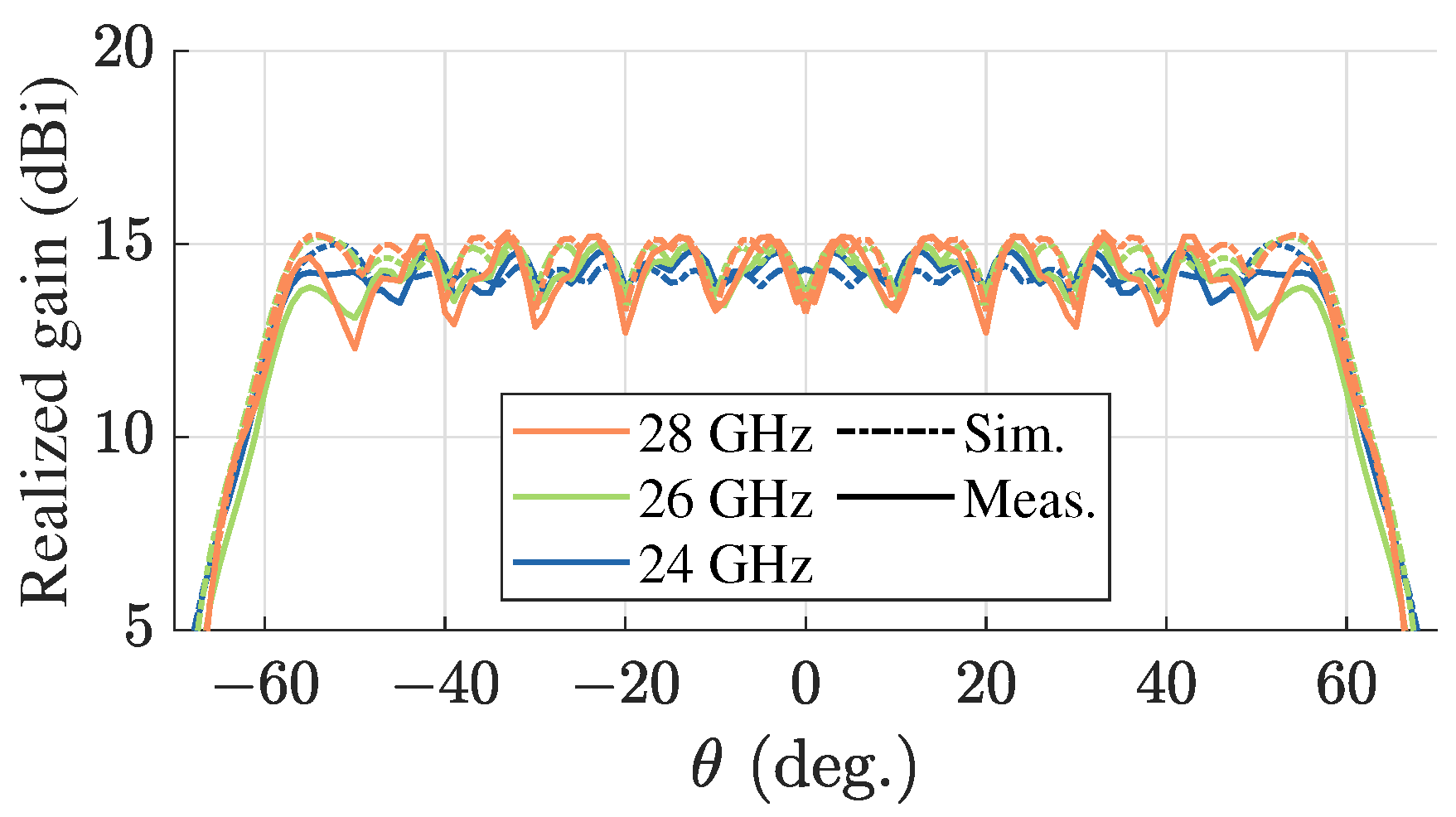
The lens antenna is simulated using the time-domain solver of CST and measured using an Anritsu MS4647B VNA and the anechoic chamber at KTH. Figure 6 presents the reflection coefficients for ports 1 to 6. The results for ports 7 to 11 are symmetric to ports 1 to 5 and are omitted. The reflection coefficients are below approximately −13 dB and −14 dB in the operational band from 24 to 28 GHz in measurements and simulations, respectively. Figure 7 presents −2 dB and −3 dB contour curves of the measured and simulated normalized radiation pattern envelopes in -coordinates at 24, 26, and 28 GHz. The coordinates are defined as u = and v = , where and are indicated in Figure 2a. The beam steering plane of the antenna corresponds to = (i.e., u = 0). Only ports 1 to 6 are measured, and the measured results for are obtained by mirroring the results for . At 24 GHz and 26 GHz, the −2 dB contour curve is simply closed, meaning that the gain varies less than 2 dB throughout the steering range. At 28 GHz, the −2 dB contour curve corresponding to the simulated results is simply closed indicating a gain variation of less than 2 dB throughout the steering range. The −2 dB contour curve corresponding to the measured data is almost simply closed indicating that the gain variation is typically 2 dB in the steering range, with regions of more gain variation. Figure 8 presents the simulated and measured realized gain envelope at 24, 26, and 28 GHz in the steering plane ( = ). The measured and simulated gain varies from 12.3 to 15.2 dBi and 13.7 to 15.3 dBi, respectively, within the operational band and steering range. The gain variation at 24 GHz is approximately 1 dB in the steering range. We note that the measured gain at is almost 3 dB lower than the peak gain at 28 GHz and that the discrepancy between the simulations and measurements are attributed to errors in the permittivity of the lens material and the assembly of the lens antenna as detailed in the next section. The angular range in the orthogonal direction, i.e., , is determined by the aperture of the flare and may be adjusted to the given requirements.
4. Discussion
Table 1 compares the proposed lens antenna with the reported wide-scanning planar lens antennas with stable gain. Available simulated results indicate that the gain is more stable in the presented antenna compared to the antenna based on a collimated lens [20]. In fact, the gain stability in the antenna with a collimated lens is inherently limited by the beam correlation. The gain variation using the collimated lens cannot be smaller than approximately −2 dB in a practical device as the radiation efficiency becomes prohibitively low for many applications. This limitation is not present in the lens antenna based on the non-collimated lens described here. The increased gain stability compared to the antenna based on the collimated lens comes at the cost of reduced aperture efficiency. We note also that the gain variation in the service area of the antenna is slightly smaller compared to the alternative antenna solution based on a non-collimating lens [22], and additionally, the proposed lens has a smaller refractive index range than the alternatives [21,22]. The smaller refractive index range can simplify the realization of the lens antenna depending on its implementation, for instance if the refractive index is realized using quasi-periodic structures such as the lenses in [12]. Furthermore, if the lens is implemented by shaping the housing PPW as in a geodesic lens [22], a smaller refractive index range implies an antenna design with a lower profile. For instance, the geodesic lens in [22] has a height of roughly 0.8R. Conversely, the corresponding height of a geodesic lens equivalent of the graded-index lens proposed here is roughly 0.5R. Lastly, we note that the service area of the proposed antenna is wider than that of [21] and that the beam resolution is higher in the presented antenna, compared to the antenna in [22]. The wide service area of the antenna is useful for reducing the number of antennas needed in each base station, and the high beam resolution provides a high degree of flexibility for the antenna to operate in different scenarios.
The performance of the antenna presented here is evaluated through numerical simulations using commercial software. The simulations are verified with measurements in an anechoic chamber, and we observe a good agreement between performance predictions and measurements. The noted discrepancies between the simulated and measured results are attributed to errors in the assumed permittivity of the material used to produce the lens and the assembly of the antenna pieces. Importantly, the dielectric lens is produced using additive manufacturing with an FDM printer, and as a result, the realized relative permittivity can be different from the nominal value of the filament due to small air cavities and other deformations produced in the printing process. It is also worth noting that the results presented here are for an antenna isolated from its fixture and other environmental factors. Future tests (either numerical simulations or measurements) of the antenna in a realistic communication link are needed to validate the performance in its intended operational environment, but such tests are considered out of the scope of this work as they are application dependent.
5. Conclusions
We proposed the use of a rotationally symmetric virtual image lens to produce planar lens antennas with stable gain throughout a wide beam steering range. Specifically, we overcome the strong gain fluctuations typically associated with beam switching antennas based on quasi-optical beamformers using a virtual image lens that produces a non-collimated beam with a wide beam width. We also show how the image position of the virtual image lens can be tuned to design lens antennas with different beam widths. A demonstrator lens antenna is reported with 11 rectangular waveguide feeds placed along the border of the lens, each producing a beam within a angular range. By considering the angular separation between the feeding elements, we tune the image position of the lens so that the antenna produces a reduced gain variation within the service area of the beam. Specifically, in the presented lens antenna, the gain roll-off is less than 2 dB throughout the scanning range over an operational bandwidth from 24 to 28 GHz. Compared to previously reported wide-steering lens antennas with stable gain [21,22], the proposed antenna is easier to realize due to the relatively small refractive index range of the lens. The antenna presented here is evaluated using simulations verified by measurements in an anechoic chamber. The antenna is intended for applications where a stable service is needed in a wide angular range, such as future high-frequency communication systems. Further tests are needed to verify the antenna in the intended operational environment.
Author Contributions
Conceptualization, N.J.G.F.; methodology, O.Z., N.J.G.F. and O.Q.-T.; software, O.Z.; validation, O.Z., N.J.G.F. and O.Q.-T.; formal analysis, O.Z. and N.J.G.F.; investigation, O.Z., N.J.G.F. and O.Q.-T.; resources, O.Q.-T.; data curation, O.Z., N.J.G.F. and O.Q.-T.; writing–original draft preparation, O.Z.; writing–review and editing, O.Z., N.J.G.F. and O.Q.-T.; visualization, O.Z.; supervision, N.J.G.F. and O.Q.-T.; project administration, N.J.G.F. and O.Q.-T.; funding acquisition, O.Q.-T. All authors have read and agreed to the published version of the manuscript.
Funding
The work of O.Z. and O.Q.-T. was partially funded by the ESA ARTES Advanced Technology contract no. 4000125905/18/NL.
Data Availability Statement
The data presented in this manuscript are available upon reasonable request from the corresponding author.
Acknowledgments
The authors would like to thank the Premix group for supplying the filaments used for the manufacturing of the lens.
Conflicts of Interest
The authors declare no conflicts of interest.
Abbreviations
The following abbreviations are used in this manuscript:
| FR2 | Frequency Range 2 |
| QoS | Quality of Service |
| PPW | Parallel Plate Waveguide |
| PFD | Power Flux Density |
| FDM | Fused Deposition Modeling |
References
- Wang, Y.; Li, J.; Huang, L.; Jing, Y.; Georgakopoulos, A.; Demestichas, P. 5G Mobile: Spectrum Broadening to Higher-Frequency Bands to Support High Data Rates. IEEE Vehic. Tech. Mag. 2014, 9, 39–46. [Google Scholar] [CrossRef]
- Ericsson, A.B. 5G Wireless Access: An Overview. Available online: https://www.ericsson.com/en/reports-and-papers/white-papers/5g-wireless-access-an-overview (accessed on 26 February 2024).
- Cheng, Y.J.; Hong, W.; Wu, K.; Kuai, Z.Q.; Yu, C.; Chen, J.X.; Zhou, J.Y.; Tang, H.J. Substrate Integrated Waveguide (SIW) Rotman Lens and Its Ka-Band Multibeam Array Antenna Applications. IEEE Trans. Antennas Propag. 2008, 56, 2504–2513. [Google Scholar] [CrossRef]
- Ettorre, M.; Sauleau, R.; Le Coq, L. Multi-Beam Multi-Layer Leaky-Wave SIW Pillbox Antenna for Millimeter-Wave Applications. IEEE Trans. Antennas Propag. 2011, 59, 1093–1100. [Google Scholar] [CrossRef]
- Ettorre, M.; Manzillo, F.F.; Casaletti, M.; Sauleau, R.; Le Coq, L.; Capet, N. Continuous Transverse Stub Array for Ka-Band Applications. IEEE Trans. Antennas Propag. 2015, 63, 4792–4800. [Google Scholar] [CrossRef]
- Barba Molina, H.; Gonzalez Marin, J.; Hesselbarth, J. Modified planar Luneburg lens millimetre-wave antenna for wide-angle beam scan having feed locations on a straight line. IET Microw. Antennas Propag. 2017, 11, 1462–1468. [Google Scholar] [CrossRef]
- Ströber, T.; Tubau, S.; Girard, E.; Legay, H.; Goussetis, G.; Ettorre, M. Shaped Parallel-Plate Lens for Mechanical Wide-Angle Beam Steering. IEEE Trans. Antennas Propag. 2021, 69, 8158–8169. [Google Scholar] [CrossRef]
- Del Mastro, M.; Mahmoud, A.; Potelon, T.; Sauleau, R.; Quagliaro, G.; Grbic, A.; Ettorre, M. Ultra-Low-Profile Continuous Transverse Stub Array for SatCom Applications. IEEE Trans. Antennas Propag. 2022, 70, 4459–4471. [Google Scholar] [CrossRef]
- Pfeiffer, C.; Grbic, A. A Printed, Broadband Luneburg Lens Antenna. IEEE Trans. Antennas Propag. 2010, 58, 3055–3059. [Google Scholar] [CrossRef]
- Bosiljevac, M.; Casaletti, M.; Caminita, F.; Sipus, Z.; Maci, S. Non-Uniform Metasurface Luneburg Lens Antenna Design. IEEE Trans. Antennas Propag. 2012, 60, 4065–4073. [Google Scholar] [CrossRef]
- Dhouibi, A.; Burokur, S.N.; de Lustrac, A.; Priou, A. Compact Metamaterial-Based Substrate-Integrated Luneburg Lens Antenna. IEEE Antennas Wirel. Propag. Lett. 2012, 11, 1504–1507. [Google Scholar] [CrossRef]
- Lu, H.; Liu, Z.; Liu, Y.; Ni, H.; Lv, X. Compact Air-Filled Luneburg Lens Antennas Based on Almost-Parallel Plate Waveguide Loaded With Equal-Sized Metallic Posts. IEEE Trans. Antennas Propag. 2019, 67, 6829–6838. [Google Scholar] [CrossRef]
- Fan, F.; Cai, M.; Zhang, J.; Yan, Z.; Wu, J. Wideband Low-Profile Luneburg Lens Based on a Glide-Symmetric Metasurface. IEEE Access 2020, 8, 85698–85705. [Google Scholar] [CrossRef]
- Lian, J.W.; Ansari, M.; Hu, P.; Guo, Y.J.; Ding, D. Wideband and High-Efficiency Parallel-Plate Luneburg Lens Employing All-Metal Metamaterial for Multibeam Antenna Applications. IEEE Trans. Antennas Propag. 2023, 71, 3193–3203. [Google Scholar] [CrossRef]
- Ettorre, M.; Sauleau, R. Reconfigurable multi-beam pillbox antenna for millimeter wave automotive radars. In Proceedings of the 9th International Conference on Intelligent Transport Systems Telecommunications, (ITST), Lille, France, 20–22 October 2009; pp. 87–90. [Google Scholar]
- White, W. Pattern limitations in multiple-beam antennas. IRE Trans. Antennas Propag. 1962, 10, 430–436. [Google Scholar] [CrossRef]
- Stein, S. On cross coupling in multiple-beam antennas. IRE Trans. Antennas Propag. 1962, 10, 548–557. [Google Scholar] [CrossRef]
- Tekkouk, K.; Ettorre, M.; Gandini, E.; Sauleau, R. Multibeam pillbox antenna with low sidelobe level and high-beam crossover in SIW technology using the split aperture decoupling method. IEEE Trans. Antennas Propag. 2015, 63, 5209–5215. [Google Scholar] [CrossRef]
- Foglia Manzillo, F.; Śmierzchalski, M.; Le Coq, L.; Ettorre, M.; Aurinsalo, J.; Kautio, K.T.; Lahti, M.S.; Lamminen, A.E.I.; Säily, J.; Sauleau, R. A Wide-Angle Scanning Switched-Beam Antenna System in LTCC Technology With High Beam Crossing Levels for V-Band Communications. IEEE Trans. Antennas Propag. 2019, 67, 541–553. [Google Scholar] [CrossRef]
- Zetterstrom, O.; Arnberg, P.; Vidarsson, F.V.; Algaba-Brazález, A.; Manholm, L.; Johansson, M.; Quevedo-Teruel, O. V-Band Geodesic Generalized Luneburg Lens Antenna with High Beam Crossover Gain. IEEE Trans. Antennas Propag. 2023, 71, 7591–7596. [Google Scholar] [CrossRef]
- Chou, H.T.; Chang, Y.S.; Huang, H.J.; Yan, Z.D.; Lertwiriyaprapa, T.; Torrungrueng, D. Two-Dimensional Multi-Ring Dielectric Lens Antenna to Radiate Fan-Shaped Multi-Beams With Optimum Adjacent-Beam Overlapping Crossover by Genetic Algorithm. IEEE Access 2020, 8, 79124–79133. [Google Scholar] [CrossRef]
- Orgeira, O.; León, G.; Fonseca, N.J.G.; Mongelos, P.; Quevedo-Teruel, O. Near-Field Focusing Multibeam Geodesic Lens Antenna for Stable Aggregate Gain in Far-Field. IEEE Trans. Antennas Propag. 2022, 70, 3320–3328. [Google Scholar] [CrossRef]
- Luneburg, R.K. Mathematical Theory of Optics; Brown University Press: Providence, RI, USA, 1944. [Google Scholar]
- Fonseca, N.J.G.; Tyc, T.; Quevedo–Teruel, O. A solution to the complement of the generalized Luneburg lens problem. Commun. Phys. 2021, 4, 270. [Google Scholar] [CrossRef]
- Ericsson, A.B. Leveraging the Potential of 5G Millimeter Wave. Available online: https://www.ericsson.com/en/reports-and-papers/further-insights/leveraging-the-potential-of-5g-millimeter-wave (accessed on 1 September 2023).
- Tyc, T.; Herzánová, L.; Šarbort, M.; Bering, K. Absolute instruments and perfect imaging in geometrical optics. New J. Phys. 2011, 13, 115004. [Google Scholar]
- Poyanco, J.M.; Zetterstrom, O.; Castillo-Tapia, P.; Fonseca, N.J.G.; Pizarro, F.; Quevedo-Teruel, O. Two-Dimensional Glide-Symmetric Dielectric Structures for Planar Graded-Index Lens Antennas. IEEE Antennas Wirel. Propag. Lett. 2021, 20, 2171–2175. [Google Scholar] [CrossRef]
- CST Microwave Studio, Version 2022. Available online: https://www.3ds.com/products-services/simulia/products/cst-studio-suite/ (accessed on 18 August 2023).
Figure 1.
(a) Refractive index profile of virtual image lenses with different image positions and ray paths in virtual image lenses with (b) , (c) , (d) , and (e) (Luneburg lens).
Figure 1.
(a) Refractive index profile of virtual image lenses with different image positions and ray paths in virtual image lenses with (b) , (c) , (d) , and (e) (Luneburg lens).

Figure 2.
(a) Model of the lens antenna. Zoomed views of the (b) feeding waveguide and (c) exponential flare.
Figure 2.
(a) Model of the lens antenna. Zoomed views of the (b) feeding waveguide and (c) exponential flare.
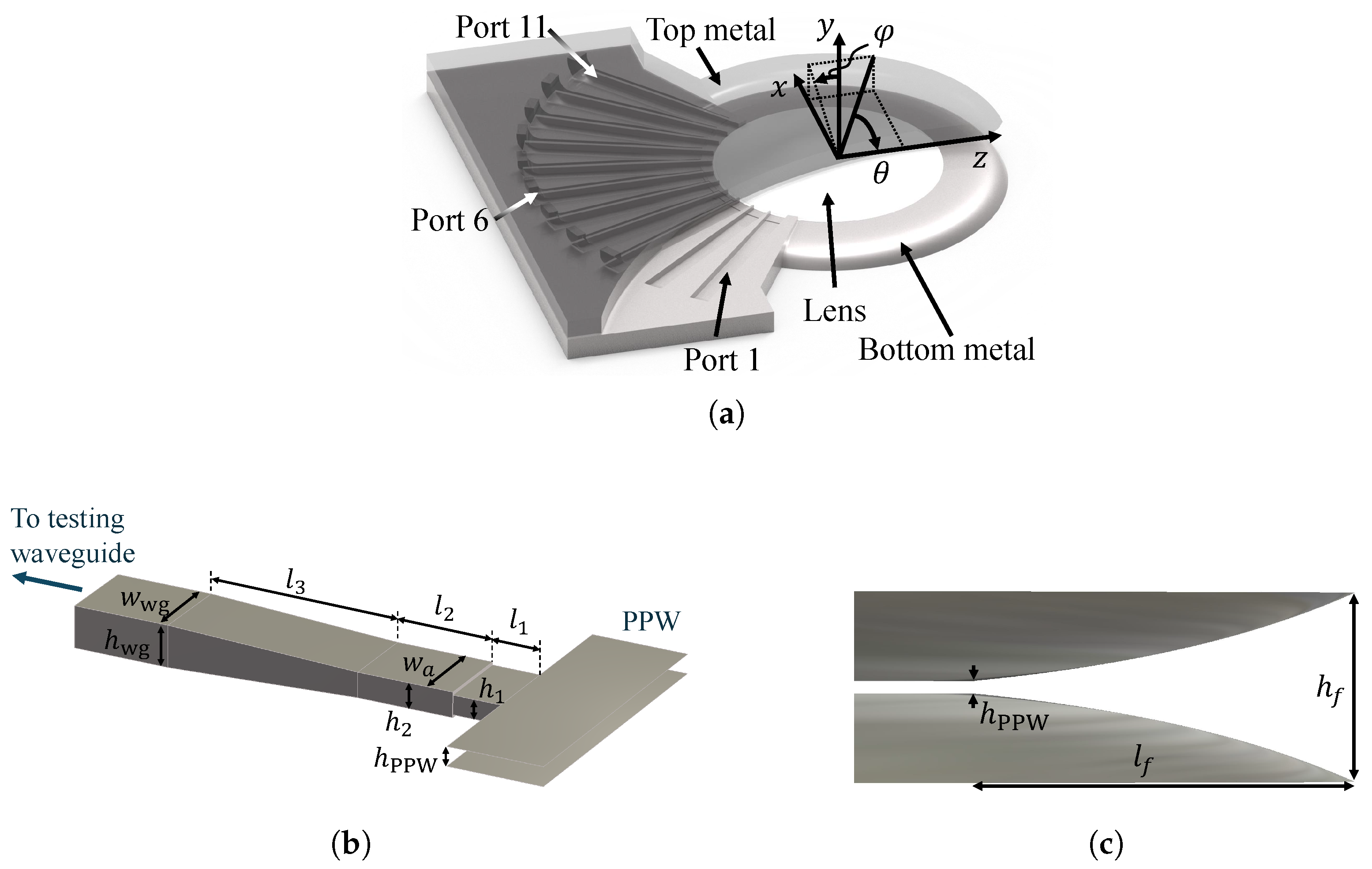
Figure 3.
(a) Realized gain at 26 GHz for the center beam. (b) Minimum and maximum gain within the service area of a beam.
Figure 3.
(a) Realized gain at 26 GHz for the center beam. (b) Minimum and maximum gain within the service area of a beam.
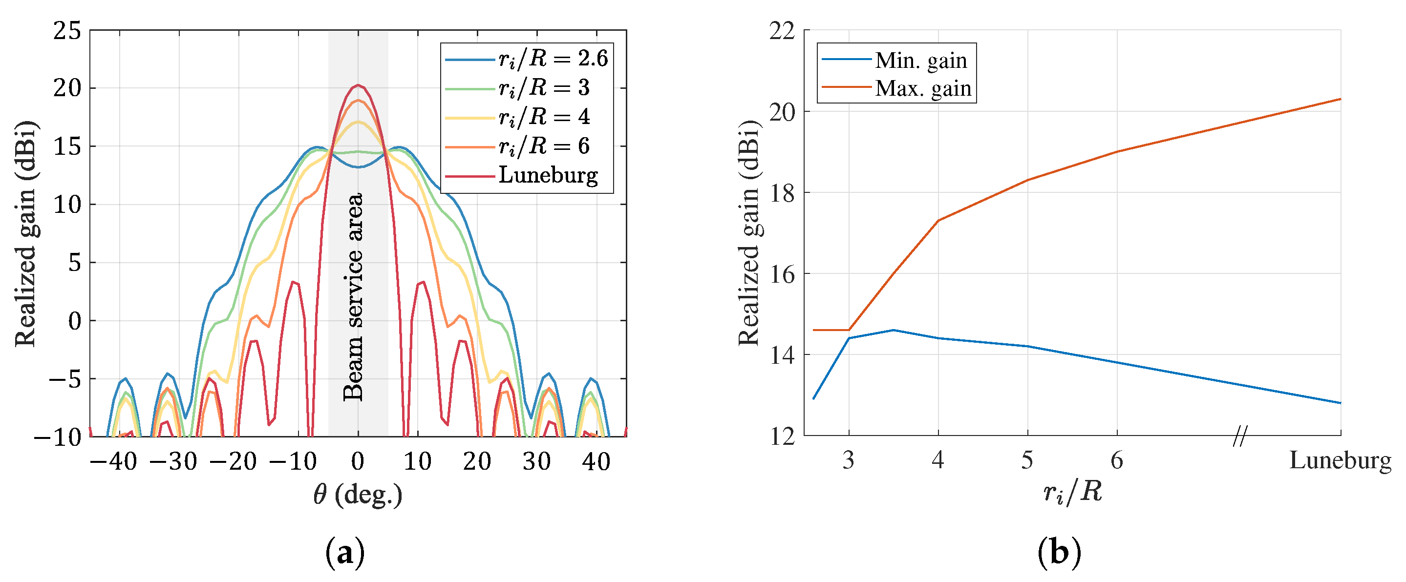
Figure 4.
(a) Effective refractive index at 26 GHz for a PPW of height h = 2 mm partially loaded with a dielectric with permittivity = . The inset shows a section of the parallel plate waveguide (PPW) indicating relevant dimensions. (b) Thickness of the dielectric slab required to mimic the refractive index in Figure 1. The inset shows the implemented lens with a radius of R = 50 mm. (c) Normalized electric field at 26 GHz produced by the virtual image lens excited at its border.
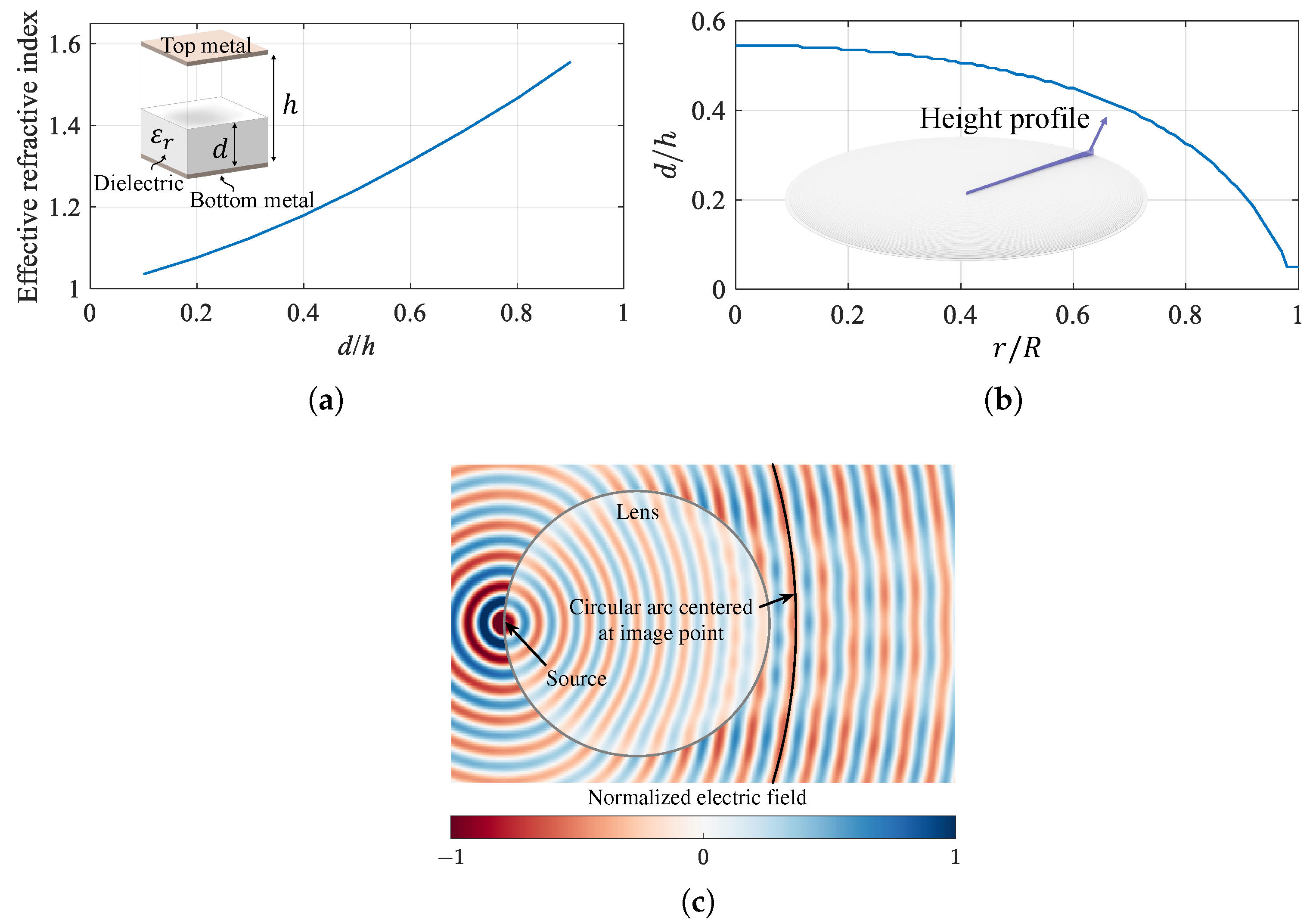
Figure 5.
Manufactured prototype of the lens antenna. The figure displays the lens attached to the bottom metallic plate.
Figure 5.
Manufactured prototype of the lens antenna. The figure displays the lens attached to the bottom metallic plate.
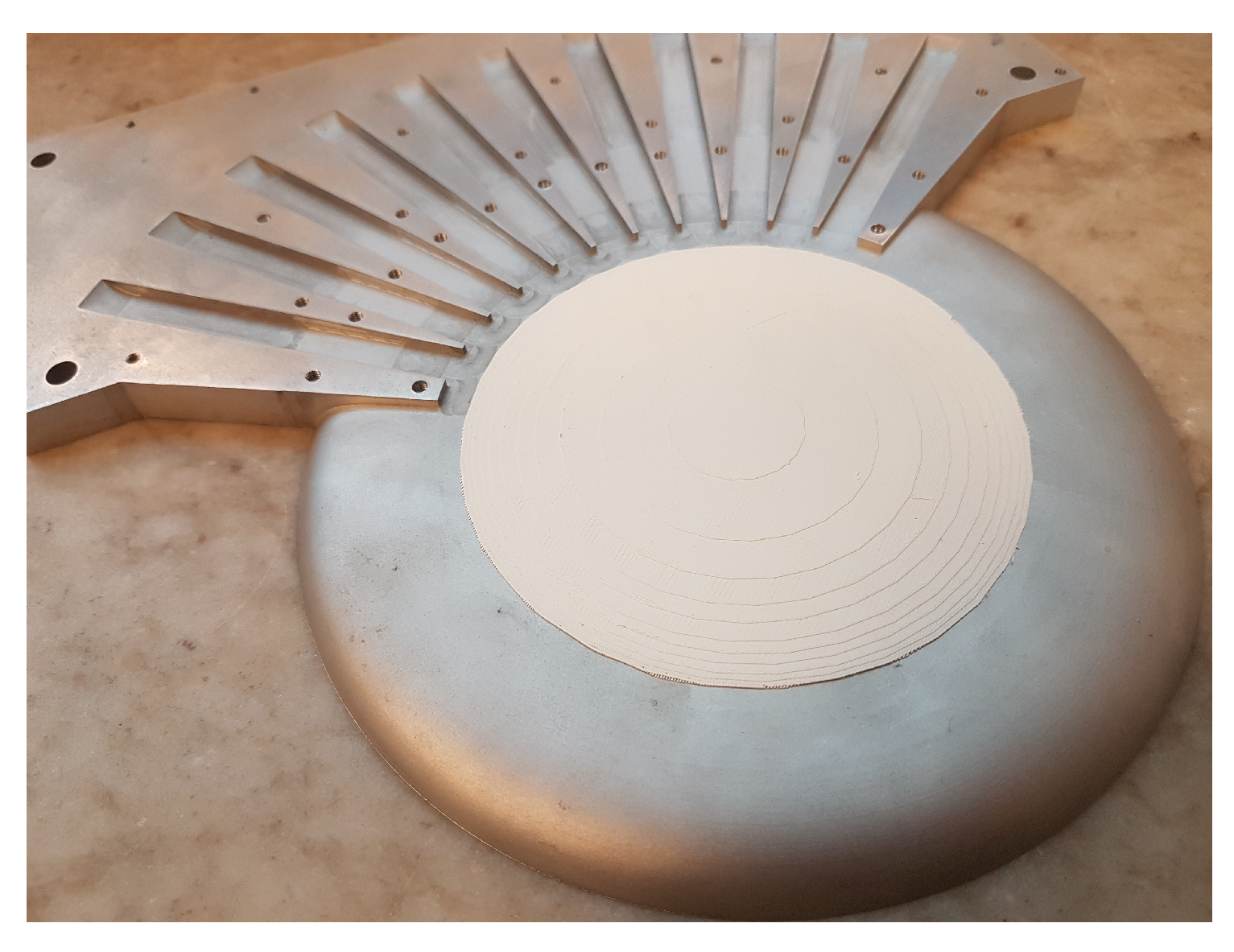
Figure 6.
Simulated (dashed lines) and measured (solid lines) reflection coefficients of ports 1–6.
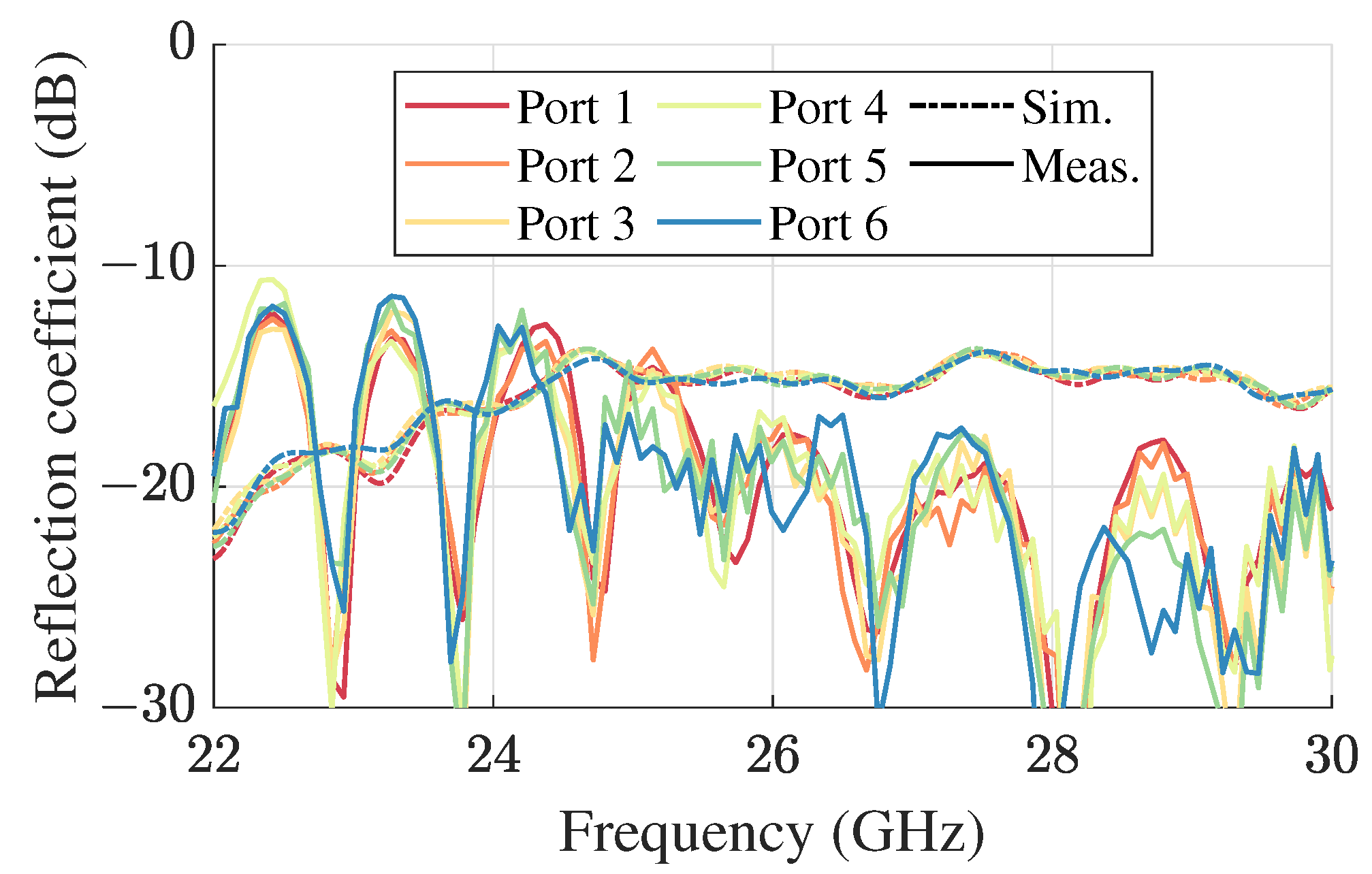
Figure 7.
Simulated (dashed lines) and measured (solid lines) aggregated normalized radiation patterns at (a) 24 GHz, (b) 26 GHz, and (c) 28 GHz. The results for are obtained by mirroring the results for .
Figure 7.
Simulated (dashed lines) and measured (solid lines) aggregated normalized radiation patterns at (a) 24 GHz, (b) 26 GHz, and (c) 28 GHz. The results for are obtained by mirroring the results for .
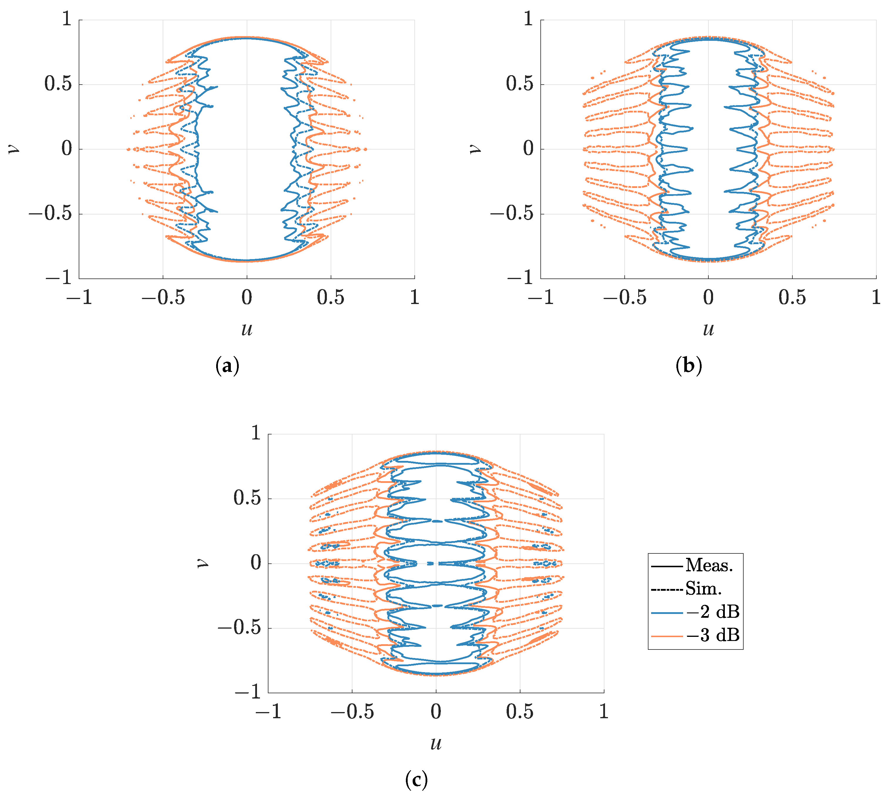
Figure 8.
Simulated (dashed lines) and measured (solid lines) realized gain envelope in the steering plane ( = ). The results for are obtained by mirroring the results for .
Figure 8.
Simulated (dashed lines) and measured (solid lines) realized gain envelope in the steering plane ( = ). The results for are obtained by mirroring the results for .

Table 1.
Comparison of reported wide-scanning planar lens antennas with stable gain.
| Reference | Frequency | Refractive Index | Smallest/Largest Gain Variation * |
|---|---|---|---|
| [20] | 57–67 GHz | 1–1.26 | dB/4 dB |
| [21] | 38 GHz | 1–1.35 | 1 dB † |
| [22] | 30–35 GHz | 1–1.6 § | 1 dB/3 dB |
| This work | 24–28 GHz | 1–1.27 | 1 dB/2 dB |
* corresponding to simulated data in the steering range for a given frequency; † only one frequency sample is presented; § converted from the height profile.
Disclaimer/Publisher’s Note: The statements, opinions and data contained in all publications are solely those of the individual author(s) and contributor(s) and not of MDPI and/or the editor(s). MDPI and/or the editor(s) disclaim responsibility for any injury to people or property resulting from any ideas, methods, instructions or products referred to in the content. |
© 2024 by the authors. Licensee MDPI, Basel, Switzerland. This article is an open access article distributed under the terms and conditions of the Creative Commons Attribution (CC BY) license (https://creativecommons.org/licenses/by/4.0/).
Share and Cite
MDPI and ACS Style
Zetterstrom, O.; Fonseca, N.J.G.; Quevedo-Teruel, O. Wide-Angle Beam-Switching Antenna with Stable Gain Based on a Virtual Image Lens. Electronics 2024, 13, 1034. https://doi.org/10.3390/electronics13061034
AMA Style
Zetterstrom O, Fonseca NJG, Quevedo-Teruel O. Wide-Angle Beam-Switching Antenna with Stable Gain Based on a Virtual Image Lens. Electronics. 2024; 13(6):1034. https://doi.org/10.3390/electronics13061034
Chicago/Turabian StyleZetterstrom, Oskar, Nelson J. G. Fonseca, and Oscar Quevedo-Teruel. 2024. "Wide-Angle Beam-Switching Antenna with Stable Gain Based on a Virtual Image Lens" Electronics 13, no. 6: 1034. https://doi.org/10.3390/electronics13061034
Note that from the first issue of 2016, this journal uses article numbers instead of page numbers. See further details here.